

Page 1

40040005 rev. 000
USER MANUAL
Page 2

40040005 rev. 000
Page 3

Copyright 2005
BTE Technologies
All Rights Reserved
Information in this document is subject to change
without notice. Companies, names and data used in
examples are fictitious unless otherwise noted. No
part of this manual may be reproduced or transmitted
in any form or by any means electronic, mechanical, or
otherwise, including photocopying and recording or in
connection with any information storage and retrieval
system, without prior permission from BTE Technologies.
BTE Technologies, Inc.™ may have patents or pending
patent applications, trademarks copyrights or other
intellectual property rights covering subject matter in this
document. The furnishing of this document does not give
you license to these patents, trademarks, copyrights, or
other intellectual property except as expressly provided in
any written license agreement from BTE Technologies, Inc.™
Printed in the U.S.A.
This manual supports the BTE Multi-Cervical™ Unit
Rev. 000
BTE Technologies
7455-L New Ridge Road
Hanover, MD 21076
Phone: 410.850.0333
Toll Free: 800.331.8845
Fax: 410.850.5244
www.BTEtech.com
40040005 rev. 000
Page 4

Warranty
We guarantee that the BTE Technologies, Inc. rehabilitation products
are free of manufacturer defects in both workmanship and material.
We will replace or repair defective parts or equipment for a period
of time and in accordance with the conditions set forth below:
This warranty covers the structure and framework for 1 year of normal
institutional use. All mechanical components including bearings,
bushings, pulleys and glides are warranted from manufacturer
defects in both workmanship and material for a one-year period.
Cords and padding are covered for a 1-year period under normal use.
This limited warranty is in lieu of all warranties, expressed or implied
and all other obligations or liabilities on the part of BTE Technologies
Inc. We neither assume nor authorize any person to assume any other
obligation or liability in connection with the sale of this product.
Under no circumstances shall BTE Technologies, Inc. be liable by virtue
of this warranty or otherwise, for damage to any person or property what
so ever for any special, indirect, secondary or consequential damage of
any nature however arising out of the use or inability to use this product.
This limited warranty applies only while the BTE Technologies, Inc. product
remains in the possession of the original purchaser and has not been
subject to accident, misuse, abuse, unauthorized modification, failure
to follow instructional use, failure to do proper maintenance, incorrect
adjustments or failure due to cause beyond the manufacture’s control.
Disclaimer
The information presented in this manual is given in good faith and is
to the best of our knowledge accurate. However, anyone who uses this
information in any way does so entirely at his or her own risk. Neither BTE
Technologies, Inc., its officers nor their representatives can accept any
responsibility for any damage or injury incurred as a result of information
presented here except under the terms of the product warranty.
Class A Digital Device
This equipment has been tested and found to comply with the limits
for a Class A digital device, pursuant to part 15 of the FCC Rules.
These limits are designed to provide reasonable protection against
harmful interference when the equipment is operated in a commercial
environment. This equipment generates, uses, and can radiate
radio frequency energy and, if not installed and used in accordance
with the instruction manual, may cause harmful interference to
radio communications. Operation of this equipment in a residential
area is likely to cause harmful interference in which case the user
will be required to correct the interference at his own expense.
40040005 rev. 000
Page 5

USER
MANUAL
01 - Installation and Setup
02 - General Operation
03 - Client Information
04 - Templates
05 - Calibration
06 - Protocols
07 - Reports
40040005 rev. 000
08 - Cervical Conditioning
09 - Maintenance
10 - The Melbourne Protocol
Page 6

Page 7

01 - INSTALLATION & SETUP
Introduction 3
MCU™ Components 3
section 01
Multi-Cervical
™ Station 3
Calibration Tools 4
Computer Equipment and Cart 4
Assembly Instructions 4
Setting up the MCU
™ Station 4
Setting up the Computer Equipment and Cart 6
Strongly Recommended Additional Purchases 7
Computer Care 7
Check Computer Cables 7
Environment Requirements 7
40040005 rev. 000
page
1
Page 8

section 01
page
2
40040005 rev. 000
Page 9
section 01
INSTALLATION AND SETUP
I. INTRODUCTION
When you first look at the MCU™, it may be difficult to imagine that a cervical assessment can
be so simple. However, once you familiarize yourself with the basic components of the unit and
practice its operation following appropriate training, you will wonder how you ever did assessments without it.
This MCU™ Operator’s Manual will review the basic components of the Multi Cervical™ Unit.
Once you are familiar with the components, you can explore the techniques and protocols for
performing a cervical assessment, including range of motion and isometric strength testing.
This Manual will also review the different types of reports that are automatically generated
using the information acquired throughout the assessment, as well as the clinical documentation you provide the Objective Documentation Evaluation System (ODES™) computer diagnostic
system component.
BTE Technologies recommends that the Multi-Cervical™ Unit be used in conjunction with a certified training program on The Melbourne Protocol. Two-day comprehensive training programs
are tailored to suit the specific needs of your facility. Refer to Section 10 for more information.
II. MCU™ COMPONENTS
DO NOT CHANGE OR MODIFY ANY COMPONENTS
Any changes or modifications, especially to the wireless components, not expressly approved
by BTE Technologies, Inc. could void the user’s authority to operate the equipment.
A. MULTI CERVICAL™ STATION
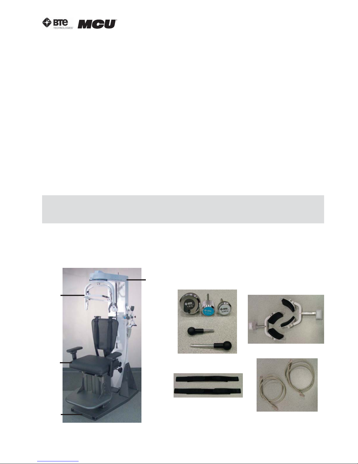
The Multi Cervical™ Station consists of the base, column with weight stack, seat, halo,
weight stack pins, ROM stop, (2) head braces, (3) Velcro straps, and (4) RJ45 cables - 2
short and 2 long (Figure 1-1).
Column
Halo
Seat
Weight Stack Pins
& ROM Stop
Head Braces
RJ45 Cables
Velcro Straps
Base
Figure 1-1. Multi-CervicalTM Station
40040005 rev. 000
page
3
Page 10
section 01
B. CALIBRATION TOOLS
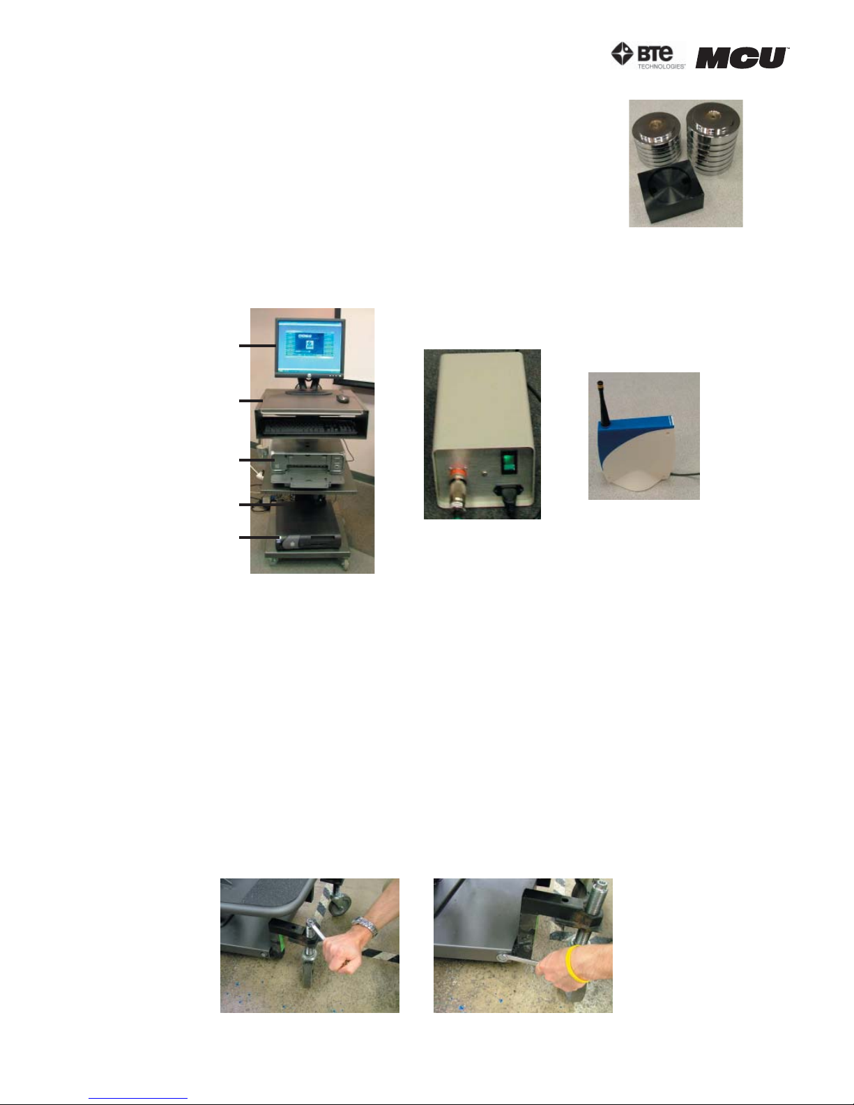
The MCU™ calibration kit consists of (1) calibration block, (1) 10 lb.
weight, and (1) 15 lb. weight (Figure 1-2).
C. COMPUTER EQUIPMENT AND CART
The computer equipment consists of a computer cart, LCD monitor, CPU, printer, speakers,
isolation transformer, and a wireless hub (Figure 1-3).
LCD Monitor
Computer Cart
Printer
Figure 1-2.
Calibration Tools
Isolation
Transformer
Wireless Hub
Speakers
CPU
Figure 1-3. Computer Equipment and Cart
III. ASSEMBLY INSTRUCTIONS
Once the MCU™ Station and computer cart have been unpacked, you are ready to start assembling the unit.
A. SETTING UP THE MCU™ STATION
The MCU™ is shipped on casters to provide maximum protection in transit and ease of
installation. The caster assemblies provide adjustable ground clearance. The system is
shipped in the highest position to clear ramps, curbs, and thresholds, but it can also be
lowered to pass under low doorways.
Step 1. Move the MCU™ to the location you wish it to be used. Using a 3/4” wrench, lower
each caster a small amount until the MCU™ base is resting on the ground. Once the base
is on the ground, remove the casters (Figure 1-4).
Lower the Casters
Remove the Casters
Figure 1-4. Lowering and Removing the Casters
page
4
40040005 rev. 000
Page 11
section 01
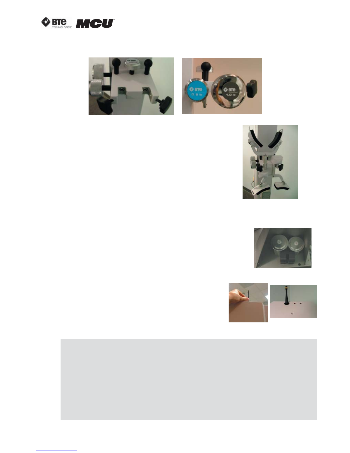
Step 2. Locate the weight stack pins and ROM stop pin and place them in the corresponding holes on the calibration plate (Figure 1-5).
Figure 1-5. Location of Weight Stack Pins & ROM STop Pin
Step 3. Locate the head braces and secure them to the calibration plate (Figure 1-6).
Figure 1-6. Head Braces
Secured to Column
Step 4. Locate the Velcro straps and RJ45 cables. These may be placed on the computer
cart.
Step 5. Locate the calibration weights and calibration block and
place them in the triangular bracket on the base (Figure 1-7).
Figure 1-7. Location
of Calibration Tools
Step 6. Locate the 2 antennas and then locate the farright hole on the top back of the MCU™ station. Insert
one of the antennas through this hole and secure it to the
PCB (Figure 1-8).
Figure 1-8. Attaching the
Antenna
ACCEPTABLE ANTENNA(S)
This device has been designed to operate with the antenna(s) listed below and having
a maximum gain of 2.7 dBi. Antennas not included in this list or having a gain greater
than 2.7 dBi are strictly prohibited for use with this device. The required antenna impedance is 50 ohms.
Acceptable antenna(s) include:
1. Linx Technologies 916MHz 1/4 Wave Whip Antenna (ANT-916-CW-QW)
To reduce potential radio interference to other users, the antenna type and its gain
should be so chosen that the equivalent isotropically radiated power (e.i.r.p.) is not
more than that permitted for successful communication.
40040005 rev. 000
page
5
Page 12
section 01
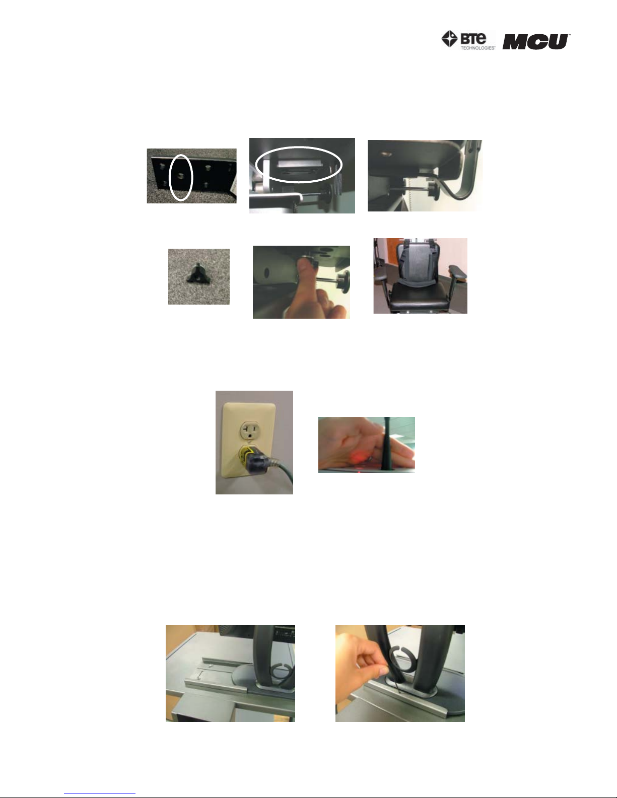
Step 7. Locate the arm rests, note which is labeled left and which is right, and attach
them to the seat on the appropriate sides (Figure 1-9). Note that the armrest is inserted
below the plastic piece that is within the bracket.
Threaded hole
Arm Rest Bracket
under Seat
Insert Arm Rest
into Bracket
on arm rest
Thread Knob into
Arm Rest Knob
Figure 1-9. Attaching the Arm Rests
Threaded Hole
Final Result
Step 8. Plug the power cord, which is located at the bottom back of the MCU™, into the
designated wall outlet. Hold your hand above the back of the MCU™, next to the antenna,
and verify a red light shines on your hand; this confirms the PCB is receiving power (Figure
1-10).
B. SETTING UP THE COMPUTER EQUIPMENT AND CART
1. LCD MONITOR
If you haven’t done so, remove the small bag from the top shelf of the computer cart
and mount the LCD monitor to the cart (Figure 1-11). Plug the power cord and serial
cable into the back of the LCD monitor.
Slide monitor
through brackets
Figure 1-11. Securing LCD Monitor
page
6
Figure 1-10. Plugging in the MCU
Secure monitor
with set screw
40040005 rev. 000
Page 13
section 01
2. PRINTER
Remove the printer from its box and place it on the 2nd shelf of the computer cart. Following the instructions from the printer box, insert the ink cartridges and plug in the
power cord and USB cable. Once the computer is running and the printer is turned on,
print a test page.
3. CPU
Remove the CPU (computer tower) from its box and place it on the 3rd shelf of the computer cart. Plug in the power cord, monitor serial cable, and printer USB cable.
4. SPEAKERS
Remove the speakers from their box and place them on the 3rd shelf of the computer
cart. Plug the cable from the left speaker into the designated jack on the right speaker.
Next, plug the power cord into the designated jack on the right speaker. Finally, plug the
speaker cable, which is attached to the right speaker into the CPU.
5. KEYBOARD & MOUSE
Remove the keyboard and mouse from their box. Place the keyboard on the auxiliary
shelf of the computer cart and plug the cord into the CPU. Place the mouse on the top
shelf of the computer cart and plug the cord into the CPU.
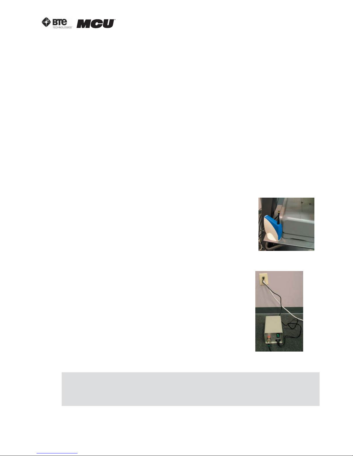
6. WIRELESS HUB
Locate the wireless Hub and place it on the 2nd shelf of the
computer cart. Note that inside of the Hub are magnets, which
are intended to keep the Hub stable on the shelf. Secure the 2nd
antenna (from Step 6 of ‘Setting up the MCU Station’) to the Hub
(Figure 1-12). Plug the USB cable into the CPU.
Note that is important to store the Hub in a location such that its
antenna is at least 3 feet from the antenna at the top of the MCU.
7. ISOLATION TRANSFORMER
Locate the isolation transformer and its power cord and place
it next to the designated wall outlet. Attach the computer cart
cable, which is located at the bottom back of the cart, to the
isolation transformer. Plug one end of the isolation transformer
power cord into the isolation transformer and the other end into
the designated wall outlet. Turn on the isolation transformer via
the green switch (Figure 1-13).
Figure 1-12. Placement of Hub
Figure 1-13. Placement of Transformer
The use of extension cords is not recommended. If an extension cord cannot be avoided, use no less than 14 gauge wire. Keep the cord as short as possible, and use only
hospital approved plugs. The extension cord MUST complete the ground from the ER
power supply cord to the wall outlet.
40040005 rev. 000
page
7
Page 14

section 01
IV. STRONGLY RECOMMENDED ADDITIONAL PURCHASES
In addition to the equipment shipped to you from BTE Technologies, the purchase of the following items from a local supplier is strongly recommended for adequate protection of your
patient data:
• Several “CD-RW” re-writable compact discs for backing up and archiving copies of patient
data
• An Uninterruptible Power Supply (UPS) unit providing at least 14 amps as a safeguard
against the permanent loss of patient information due to power surge or electrical power
failure.
IMPORTANT
In case of a malfunction, your computer can be repaired or replaced, but your valuable patient
data can only be restored from copies kept on “back-up” CDs (See Section 2 - General Information).
• Disinfectant wipes to clean the commonly used surfaces on the machine and components.
VI. COMPUTER CARE
A computer’s hard disk is vulnerable to loss of data and “corruption” of data (may not function
correctly when you attempt to retrieve patient information) from a sudden change in the level
of electrical power. In the event of a power failure, the UPS battery will generate electricity
long enough to allow you to shut down the system without damage to your patient data.
Since computers are sensitive to extremes of temperature, do not place equipment close to a
direct source of heat or cold (for example, in direct sunlight, next to a radiator or an air conditioner).
Do not install any additional software onto the controlling computer. The BTE Technologies
MCU™ system is in constant communication with the computer, so a “clean”, dedicated computer system is crucial to the integrity of this communication system. Lastly, your computer will
not be covered under the warranty if any unapproved software has been installed.
IMPORTANT
Handle your computer with extreme care. A drop or a bump, even from a height of 3-4 inches,
may cause serious damage, which is not covered by the warranty.
A. CHECK COMPUTER CABLES
Check that all cables are securely connected to the computer. Just about every cable
connector is made in such a way that it will only attach in its appropriate location. If the
cables are not secured properly, there may be an interruption of the data transmission,
resulting in error messages.
B. ENVIRONMENT REQUIREMENTS
The MCU™ is designed to operate within the following environmental conditions:
o
Ambient Temperature: 50
Relative Humidity: 30% to 75%
Atmospheric Pressure: 700hPa to 1060 hPa
Voltage Supply: 110-120 VAC (International Voltages differ)
F to 100oF (10oC to 40oC)
page
8
40040005 rev. 000
Page 15

02 - GENERAL OPERATION
Getting Started 3
Basic Software Navigation 3
The Windows XP Environment 3
Using the ODES Software 3
Home (Start-Up) Screen 4
Administration Menu 5
Clinic Information 6
Practitioner Information 6
Environment Settings 7
Data Acquisition Channel 7
Device Settings 7
Global Settings 8
URFIO Configuration Application 8
section 02
User Manager 9
Import, Export, and Archive Data 10
Job Demand Templates 11
Superficial Tenderness Reports 11
Protocol Hibernation 12
Remove Current Case 12
Taskbar 13
File Drop-Down Menu 13
Database Utilities 13
Compact and Repair Database 13
Back Up Database 13
Restore Database 14
Log Off and Exit 14
Calibration Drop-Down Menu 14
Statistics Drop-Down Menu 14
Employer Information 14
Patient Status Information 14
Patient Information 15
Referral Information 15
40040005 rev. 000
page
1
Page 16

section 02
Insurance Information 15
Statistical Queries 15
Real Time Analysis 15
Export Cervical Data 16
Export Admin Information 16
Import Admin Information 17
Snapshots 17
Creating a Snapshot 18
Emailing, Saving, Removing, and Viewing a Snapshot 18
Forms Drop-Down Menu 18
Utilities Drop-Down Menu 18
Standing/Sitting Tolerance Report 18
Calculators Drop-Down Menu 18
Calculator 18
Deviation Calculator 18
Digital Capture 18
Help Drop-Down Menu 19
Help Manuals 19
About 19
page
2
40040005 rev. 000
Page 17
section 02
GENERAL OPERATION
I. GETTING STARTED
Ensure that you have carefully read Section 1 of this manual prior to starting up your MCU™.
IMPORTANT
Voltages over 125V can result in eventual damage to the MCU™ electronics and produce
frequent error messages. Even if you have a dedicated circuit for your MCU™, have a technician check the outlet with a voltmeter to ensure that the wall voltage does not exceed
125 Volts (U.S. and Canada). If your wall voltage exceeds this voltage, call BTE Technologies immediately.
Damage to your MCU™ resulting from wall voltages exceeding 125 Volts is not covered under the warranty.
Step 1. After making sure everything is plugged in properly, turn on the computer.
Step 2. Once the system is booted and the MCU™ is ready to use, click on the Start Button
and select BTE URFIO Config. The URFIO Config screen will appear for 5 seconds and then disappear; however, it is still running in the background. Refer to Section IV-C on how to access
the URFIO Config screen through ODES.
Step 3. Open the software by double-clicking the ODES icon, which is located on the “desktop” of the computer monitor.
II. BASIC SOFTWARE NAVIGATION
The BTE Technologies MCU™ is controlled through its own unique software. Use this section as
both an initial primer and a to-the-point, quick reference guide to your ODES software.
A. THE WINDOWS XP ENVIRONMENT
As a new user of MCU™, it is important for you to first acclimate yourself to the Microsoft
Windows XP operating system.
Familiarize yourself with these basic functions:
Desktop – Once Windows loads up, the entire screen is taken up by the ‘desktop’.
Double-clicking the ODES ‘shortcut’ icon, which is located on the desktop, launches the
ODES software.
Minimize – Clicking this button ‘hides’ the open program and
reduces it to a button on the start bar (Figure 2-1).
Maximize/Restore – Expands the program window to fit the
size of the entire screen. If the program is already expanded,
clicking this will shrink the screen to a smaller window (Figure 2-1).
Close – Closes the active program window (Figure 2-1).
Scrollbars – Click the small black “up” and “down” arrows on the bar at the right of a
given window to scroll up and down in screens.
Minimize
Maximize
Figure 2-1. Minimize/
Maximize/Close
Close
Start bar - This horizontal bar located at the bottom of your screen displays a button of
every open program. Clicking a program name here switches you to that program.
Start button – This button is used to launch nearly every program and
function of Microsoft Windows (Figure 2-2).
40040005 rev. 000
Figure 2-2.
Start Icon
page
3
Page 18
section 02
B. USING THE ODES SOFTWARE
Once you are comfortable with Windows XP, take some time to familiarize yourself with the
general layout and functioning of the ODES software. Doing this now will maximize your efficiency down the line.
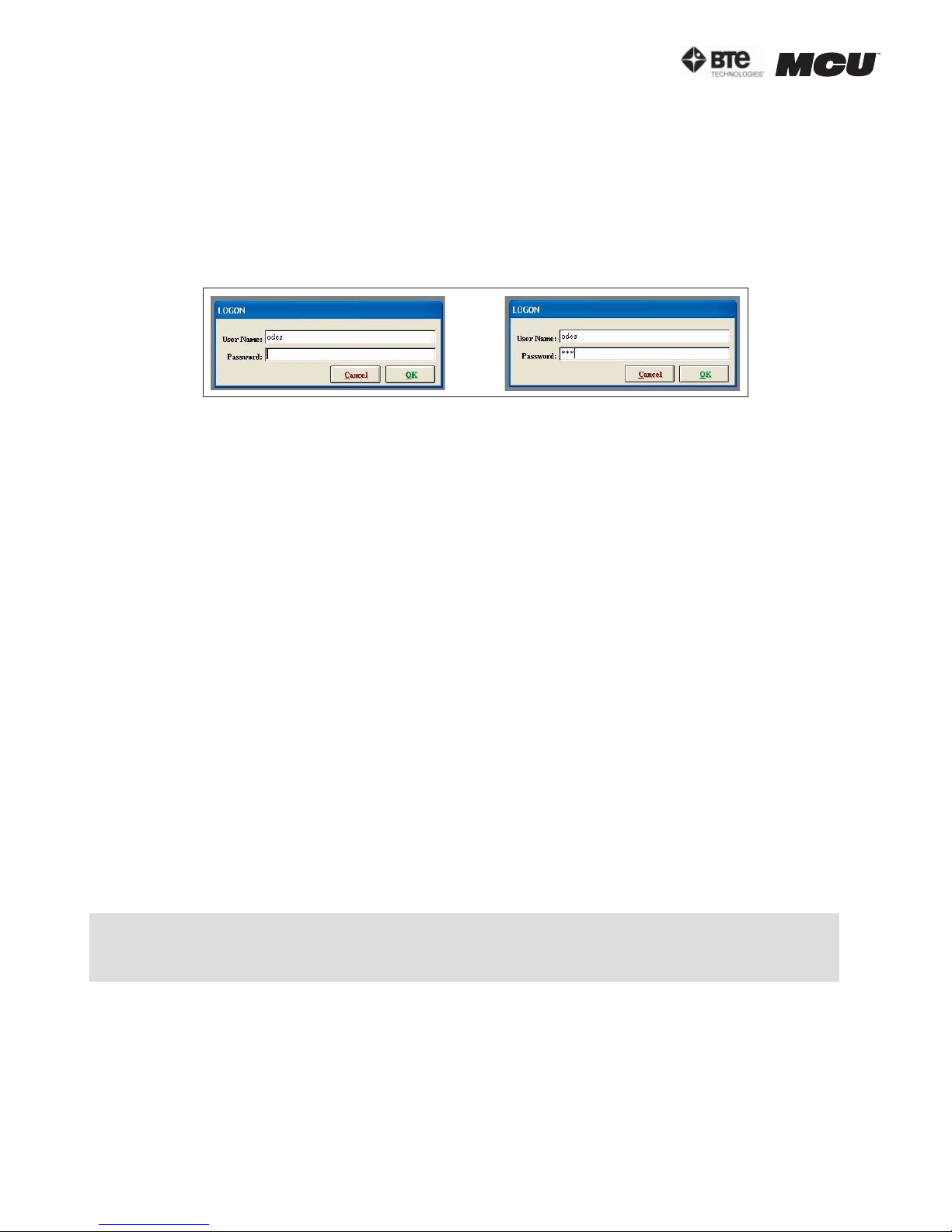
To access ODES, click on the ODES icon, which is displayed on the computer’s desktop. You
will be prompted for a username and password (Figure 2-3). The username is odes and the
password is bte (both lower case); the username and password may be modified through
the Administration Menu if you choose to do so later.
Figure 2-3. ODES Username and Password
Upon entering ODES, you will notice the following elements are used throughout:
Title Bar – The narrow blue strip located at the top of the screen which displays the database into which the data is being stored.
Taskbar – Located at the top of the screen under the title bar; while in the home screen,
this bar includes the menus: File, Calibration, Statistics, Snapshots, Forms, Utilities, Calculators, Digital Capture, Patient Standing and Sitting icons, and Help. This bar changes
depending on which area of the software you are using.
Taskbar items – Items listed under each menu title which allow you to perform an operation or to pull up a report.
Text fields – Text and numerical values are entered into “fields”. To enter text or an integer into a field, click the field, and a blinking black cursor will indicate that the field is
active. Type in the required information.
Check boxes – A checkbox is like a switch; click one to activate a setting and click it again
to de-activate the setting.
Drop-down menu – A text field with an arrowhead pointing down. When the arrowhead is
clicked, the menu drops down to show a list of options available.
III. HOME (START-UP) SCREEN
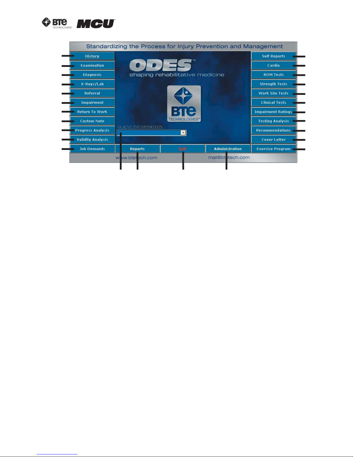
The first active screen you will see when the ODES program is initiated is the Home Screen (Figure 2-4). From this screen, all of the settings, patient information, and protocols may be accessed.
Note that the sections on Self Reports, ROM Tests, Strength Tests, and Exercise Program are
covered in this manual; however, these sections are also comprehensively covered in the training program on The Melbourne Protocol. Refer to Section 10 for more information on this training
program.
page
4
40040005 rev. 000
Page 19
section 02
A
B
C
D
E
F
G
H
I
J
K
W X Y Z
Figure 2-4. ODES Home Screen
A. History – Patient History Templates
B. Examination – Patient Examination Re-
sults Templates
C. Diagnosis – Patient Diagnosis Templates
D. X-Rays/Lab – Patient X-Ray and Lab Re-
sults Templates
E. Referral – Patient Referral Letter Templates
F. Impairment – Patient Impairment and
Disability Templates
G. Return To Work – Patient Return To Work
(RTW) Letter Templates
H. Custom Note – Blank Template for Customized Notes
I. Progress Analysis – Patient Progress
Analysis Templates
J. Validity Analysis – Comparison of Actual
Results vs. Expected Results
K. Job Demands – Comparison of Job Demand vs. Ability Demonstrated
L. Self Reports – Patient-Filled Questionnaires
M. Cardio – Cardiovascular Measurement
Protocols
L
M
N
O
P
Q
R
S
T
U
V
N. ROM Tests – Range of Motion Protocols
O. Strength Tests – Muscular Strength Pro-
tocols
P. Wo r k S i m Te s ts – Work Simulation Protocols
Q. Clinical Tests – Clinical Analysis of Pain
Protocols
R. Impairment Ratings – Patient Impairment
Ratings
S. Testing Analysis – Analysis of the Test
Results Templates
T. Recommendations – Recommendation
Letter Templates
U. Cover Letter – Cover Letter Templates
V. Exercise Program – Pre-programmed Ex-
ercises to add to a case
W. Client Information – Create and find clients and cases; display the current client
X. Reports – Create, edit, and print reports
Y. Exit – Exit the ODES software
Z. Administration – Clinic and Practitioner
Personalization Settings, Software Settings,
Heart Rate Comments, and Protocol Settings
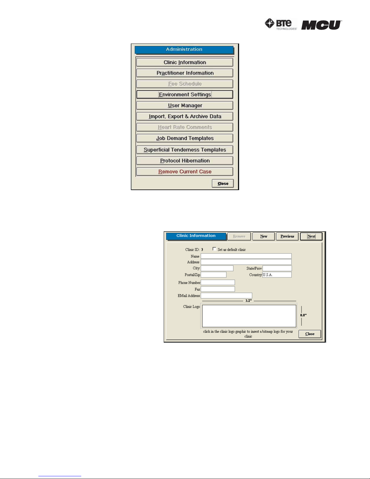
IV. ADMINISTRATION MENU
From the Administration Menu you can control several types of settings, templates, and protocols as well as remove cases (Figure 2-5).
40040005 rev. 000
page
5
Page 20
section 02
Figure 2-5. Administration Menu
A. CLINIC INFORMATION
This screen allows you to personalize the reports with your clinic’s information and logo
Figure 2-6).
Add a clinic by clicking New.
To enter a clinic logo, double click
on the Clinic Logo blank field.
Locate the saved logo file on your
hard drive.
The logo can be in any graphic file
format (.jpg, .gif, etc.) and should
be 3.2” x 0.8”, so that it doesn’t
become distorted when attached to
a report.
Edit a clinic’s information by pulling up the clinic’s screen, modifying the necessary information, and
then clicking New, Previous, Next,
or Close.
Remove a clinic by clicking Remove.
Change the default clinic by clicking Next or Previous to select the correct location and
then checking the ‘Set as default clinic’ box. Note that a default clinic cannot be removed
until another clinic has been assigned as the default.
Figure 2-6. Clinic Information
When a report is printed, the default clinic and logo are included on the report.
B. PRACTITIONER INFORMATION
This screen allows you to personalize the reports with the practitioner’s name and digital
signature (Figure 2-7).
page
6
40040005 rev. 000
Page 21
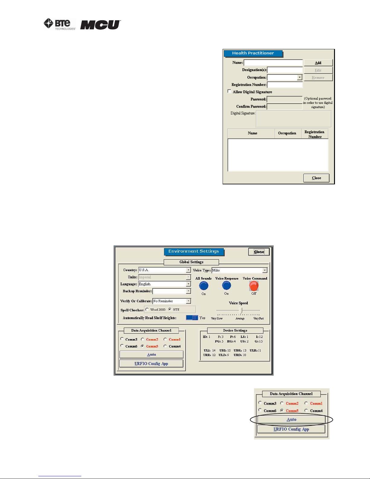
Step 1. Type in the name and demographics of the
practitioner.
Step 2. To add a digital signature, you must first
scan the signature and save it to your hard drive in
a graphic file format (.jpg, .gif, etc.).
Click the ’allow digital signature‘ box, enter a password (optional), and double click the icon in order to
locate the signature file on your hard drive.
Step 3. Click Add to include the practitioner to the
database. The name will now appear at the bottom
of the screen.
Edit the health practitioner information by highlighting the name from the list and then clicking Edit. A
practitioner may also be replaced by another within
the Edit screen. Once the changes have been made
click on Add.
section 02
Remove the health practitioner information by
highlighting the name from the list and then clicking
Figure 2-7. Health Practitioner
Remove.
C. ENVIRONMENT SETTINGS
This screen allows you to set up communication between your wireless hub and computer,
change how you interface with the software, set up reminders, and monitor the wireless
configurations (Figure 2-8).
Figure 2-8. Environment Settings
1. DATA ACQUISITION CHANNEL
Click Auto to ensure the wireless hub is communicating properly with the computer (Figure 2-9). If there is a
problem, an error message will appear stating that ODES
cannot communicate. Otherwise, if everything is working
properly, a message will appear stating the data acquisition box has been set up successfully.
40040005 rev. 000
Figure 2-9. DAQ Channel
page
7
Page 22
section 02
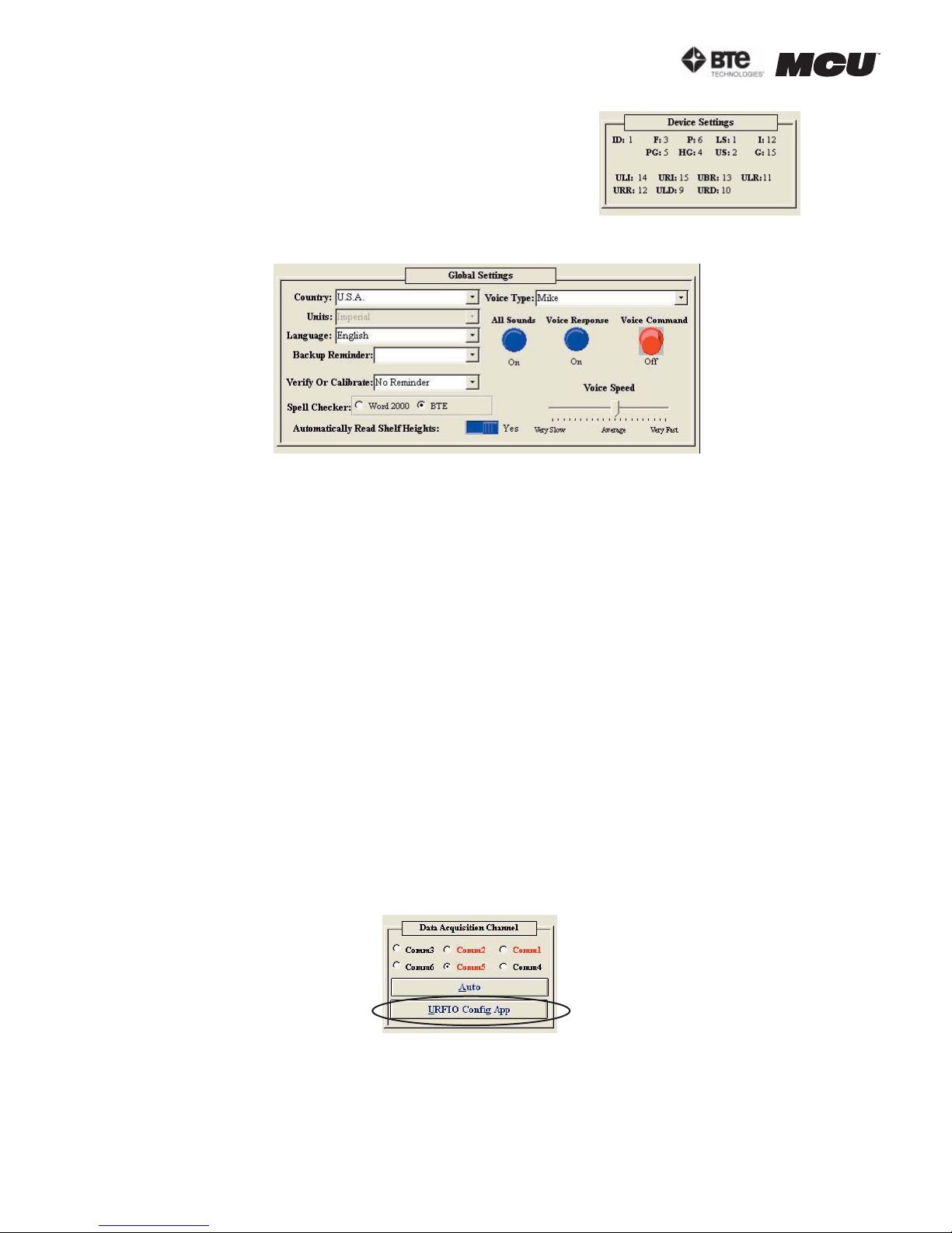
2. DEVICE SETTINGS
The Device Settings section indicates which channel the
various tools are being read from based on the set-up of
the software (Figure 2-10). This section is most helpful for
troubleshooting.
3. GLOBAL SETTINGS (FIGURE 2-11)
Country, Units, and Language – Specify the country, language, and the units of measurement to be used in printed reports.
Figure 2-10. Device Settings
Figure 2-11. Global Settings
Backup Reminder – Set reminders for backing-up your data. The recommended amount
of time between back-ups is 7 days. The backups should be saved on floppy disks, CDs,
or ZIP disks and kept separate from your system in case of fire, theft, or other equally
damaging events.
Verify or Calibrate – Set reminders for calibrating and verifying the equipment. The recommended amount of time between calibrations is 7 days, and the unit should be verified before each day of testing to ensure your tools are accurate. The accuracy of your
equipment is extremely important, particularly if your reports will be used in litigious
cases. In addition, the Reminder can be set up as ‘Remind only’ or ‘Must Be Done’.
Spell Checker – Spell check your documents using Microsoft Word or the provided Medical Spellchecker.
Automatically Read Shelf Heights – This is not used for an MCU™ system.
Voice Type – Change the type and speed of the voice interface. You may also turn the
sounds and voices on and off by clicking on the knobs.
4. URFIO CONFIGURATION APPLICATION
The URFIO Configuration Application is the portion of the software that monitors the
wireless configurations of the system (Figure 2-12).
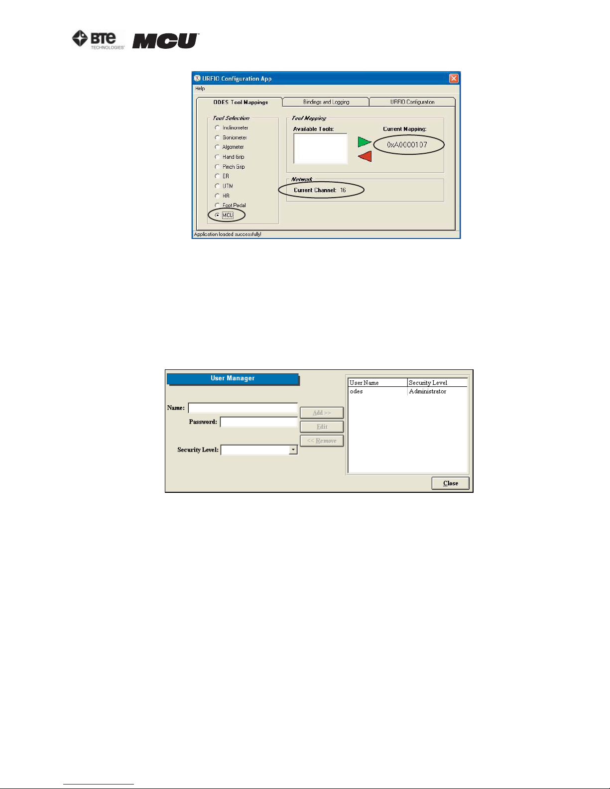
Clicking on the URFIO Configurator icon brings up the URFIO Configuration Tool Mapping
screen (Figure 2-13). This screen displays which wireless channel the system is operating on and which tool is mapped to that current wireless channel. This screen should
only be used when a new tool needs to be mapped or for troubleshooting purposes.
page
8
Figure 2-12. DAQ Channel
40040005 rev. 000
Page 23
section 02
Figure 2-13. URFIO Configuration Tool Mapping
If a tool needs to be mapped: click on the tool name under Tool Selection, highlight the
tool’s serial number under Available Tools, and then click the green arrow to map the
tool; the serial number should appear under Current Mapping. To unmap a tool, click on
the tool name under Tool Selection (the serial number must appear under Current Mapping), click on the red arrow; “Not Mapped” should appear under Current Mapping.
D. USER MANAGER
This screen allows you to add, edit, and remove users as well as set each user’s level of
rights to the software (Figure 2-14).
Figure 2-14. User Manager
To add a new user, enter a user’s name, password (case sensitive), and select a security
level from the drop-down menu. Click Add to include the new user.
When the user signs into the software, he or she will use the name and password assigned
in this screen.
Edit a user’s information by highlighting their name on the right hand side of the screen
and clicking on Edit. Once the changes have been made, click on Update.
Delete a user by highlighting their name and then clicking on Remove.
Descriptions of the security levels:
Administrator – All rights
High – All rights except User Manager
Medium High - All rights except User Manager and removal of cases
Medium - All rights except Administration
Low Medium - All rights except Administration, Reports, removal of assigned protocols
to a client, and deletion of tests
40040005 rev. 000
page
9
Page 24
section 02
Low - All rights except access to client notes, Administration, Reports, and unable to
edit, delete or create tests
Lowest - Only access to client information and client case information
E. IMPORT, EXPORT & ARCHIVE DATA
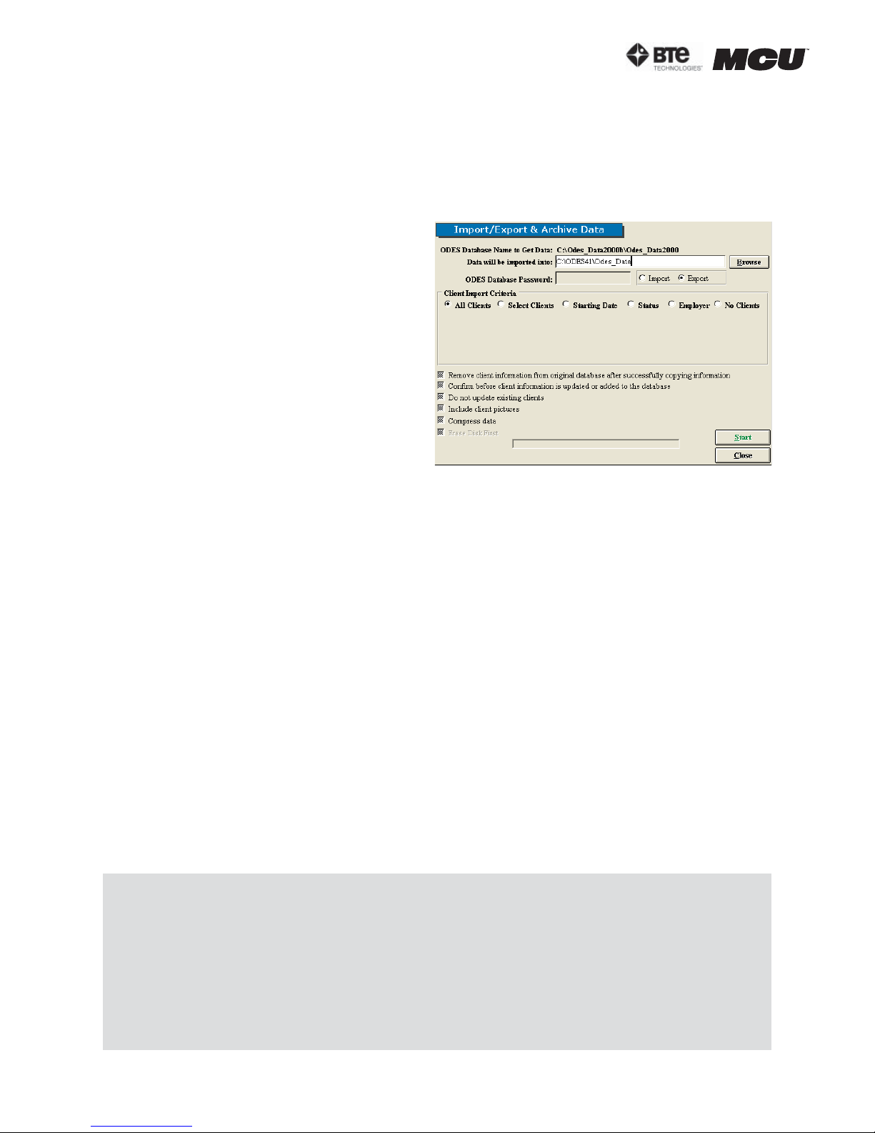
This screen allows you to import and export data with varying degrees of detail (Figure 2-
15).
Step 1. Click Browse to locate the data-
base you wish to import or export the data
from. Highlight the desired database and
click Open. The database information will
be now listed. You will be prompted to include the ODES Database Password if you
are importing or exporting from an ODES
database that is in a zipped format.
Note that the imported/exported database
cannot share the same name as an existing database. Rename the file and try
again.
Figure 2-15. Import/Export & Archive Data
Step 2. Select whether you would like to import to your current database or export data
from your current database to another.
Step 3. Select the Client Import Criteria:
All Clients – import/export all clients; new templates, custom tests, and super proto-
cols are imported/exported as well
Selected Clients – import/export select clients; new templates, custom tests, and super protocols are imported/exported as well
Starting Date – import/export according to clients’ start date; new templates, custom
tests, and super protocols are imported/exported as well
Status – import/export according to clients’ status; new templates, custom tests, and
super protocols are imported/exported as well
Employer – import/export according to clients’ employer; new templates, custom tests,
and super protocols are imported/exported as well
No Clients – import/export only new templates, custom tests, and super protocols
Step 4. Choose how you would like the data handled by clicking on the boxes next to the
options.
Step 5. Once all of the parameters are set to your preferences, click Start.
Note that when an import/export is processed, the software will run a check of the tests.
If any changes have been made to the standard tests, the software considers this as a new
test and will include copies of both. You may wish to store the duplicates under protocol hibernation or delete them. However, be aware that deleting a test also deletes the data from
that test in all patients’ files.
It is recommended that if you will be importing data obtained off-site to your main database,
you should export the main database (no clients) to the local database you will be using.
Therefore, when you import the data from your local database back to the main database,
there will be no test duplicates since the software recognizes these as the same databases.
page
10
40040005 rev. 000
Page 25
section 02
A progress screen will appear and then a notification will indicate whether the import/export was successful or not.
F. JOB DEMAND TEMPLATES
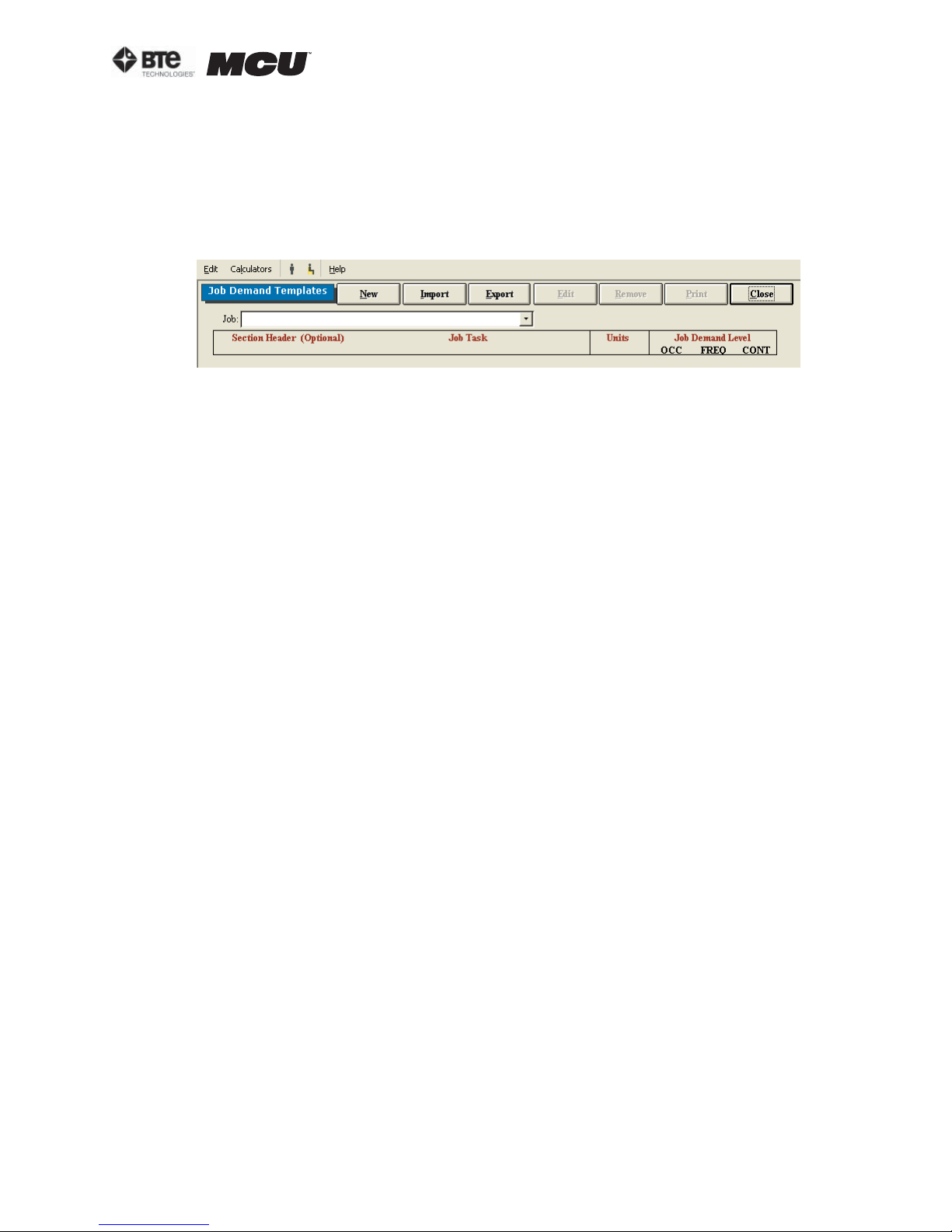
This screen allows you to create, edit, delete, and print Job Demand Templates (Figure
2-16). These templates can be used within the Job Demands screen that is accessed from
the Home Screen.
Figure 2-16. Job Demand Templates
Add a new Job Demand Template by clicking New. Enter the job title and source of the in-
formation (I.e. Job Site Analysis, Dictionary of Occupational Titles, Self Report, etc.).
The Section Header is optional; however, if Section Headers are used, the Job Demand
Templates will be grouped by Section Header (I.e. lifting, positional tolerance, mobility,
etc.) whenever the templates are printed.
Include details on job tasks, units of measurement, and the job demand level (OCCasional
– 1-33%; FREQuent – 34-66%; CONstant – 67-100%). Click Save once you have added all
the needed information.
Import templates by clicking Import and selecting the directory from which you will be
retrieving the templates and the directory into which you will be importing the templates.
You must also indicate whether you will be importing all the templates in the source ODES
database or just the current template.
Print the Job Demands Templates by clicking Print. The report can also be printed by click-
ing Export to create the report as a Word document (if you have Microsoft Office installed
on your computer), or by creating a report Snapshot (see the Snapshot section of this
manual).
Edit a Job Demand Template by selecting the job from the drop-down menu, clicking Edit,
and making any required changes.
Remove a Job Demand Template by selecting the job from the drop-down menu and click-
ing Remove.
Access a Job Demands Template within the Job Demands screen by selecting the job from
the drop-down menu and clicking Populate. This will add the header, job task, job demand
level, units, and information source to the appropriate fields. Complete the Ability Demonstrated fields, and determine whether there is a job match or not.
Add a Job Demand template from the Job Demands screen by clicking on Add to Template.
G. SUPERFICIAL TENDERNESS REPORTS
This screen allows you to create, edit, and delete Superficial Tenderness Templates. These
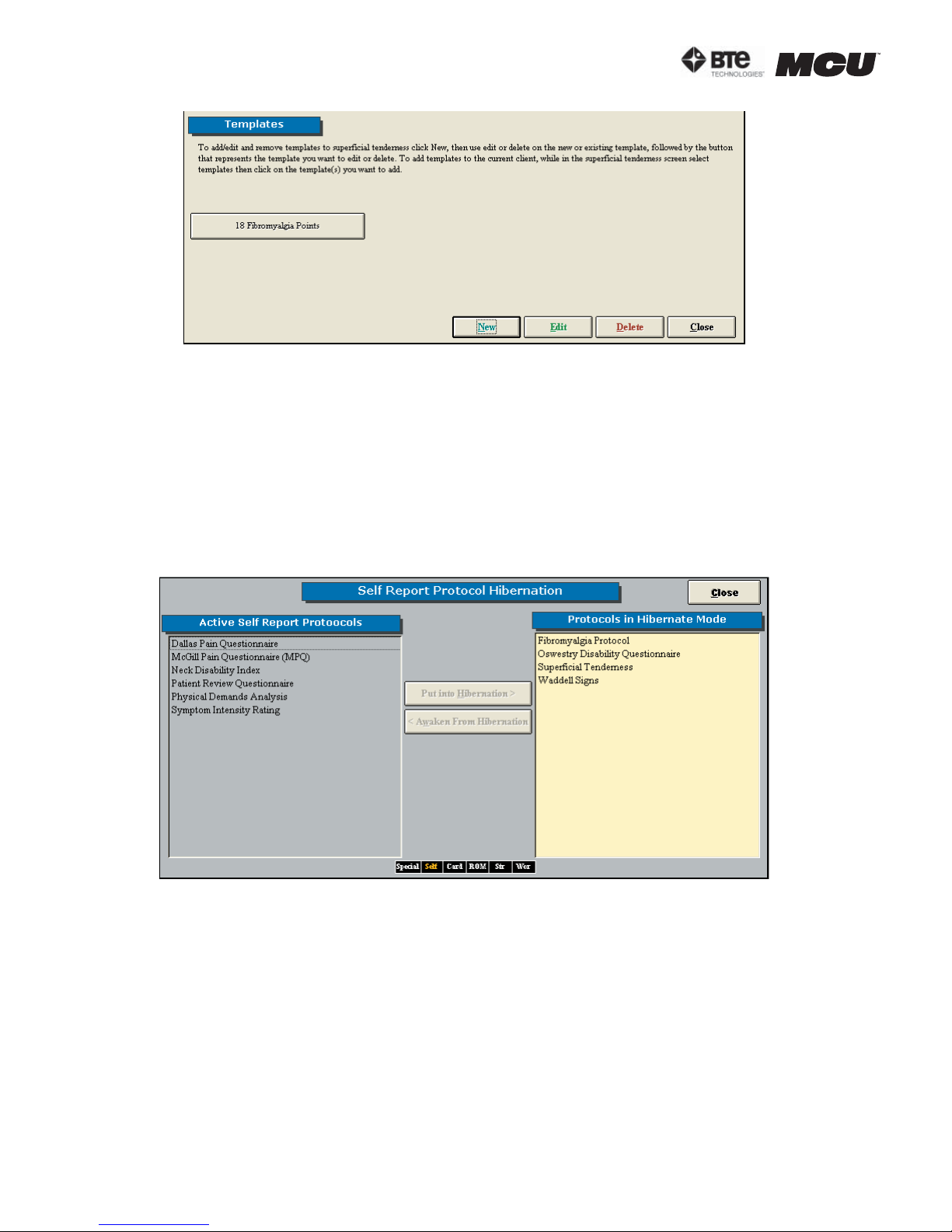
templates can be accessed through the Superficial Tenderness protocol within the Self
Reports screen (Figure 2-17).
40040005 rev. 000
page
11
Page 26
section 02
Figure 2-17. Superficial Tenderness Templates
Add a new template by clicking New.
Edit an existing template by clicking Edit and then selecting the template.
Remove an existing template by clicking Remove and then selecting the template.
H. PROTOCOL HIBERNATION
This screen allows you to place protocols, which may not be used often, in hibernation
as well as remove protocols, which may be needed, from hibernation. Moving protocols in
and out of hibernation does not delete the data or testing information. Note that protocol
hibernation can also be accessed through the protocol pages (Figure 2-18).
Figure 2-18. Protocol Hibernation
Hibernate a test by highlighting the test on the left hand side of the screen and then clicking Put into Hibernation. The test should now appear on the right screen and not the left
one.
Bring a protocol out of hibernation by highlighting the test from the right hand side of the
screen and then clicking Awaken From Hibernation. The test should now appear on the
left screen and not the right one.
I. REMOVE CURRENT CASE
This screen allows you to delete the client case that has been selected from within the home
screen. Note that once a case has been deleted, it cannot be retrieved.
Step 1. Remove the current client case by clicking Remove Current Case.
page
12
40040005 rev. 000
Page 27
Step 2. A warning will appear prior to deleting data. Click Yes to remove the case.
V. TASKBAR (FIGURE 2-19)
Figure 2-19. ODES Taskbar
A. FILE DROP-DOWN MENU
1. DATABASE UTILITIES
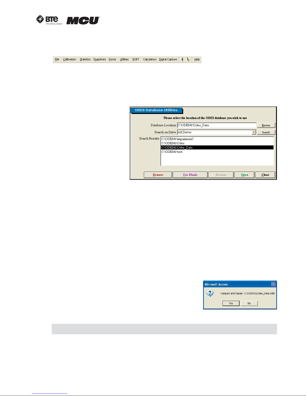
This screen allows you to open a database, create a new database, rename an existing
database, and remove an existing database (Figure 2-20).
Open a database by locat-
ing the database, double
clicking the name in the
Search Results field, and
then clicking Open. After
confirming that you would
like to open the database
selected, the home screen
will appear with the selected database available
to use. The blue title bar
at the top of the screen
should now read the
opened database.
section 02
Figure 2-20. Database Utilities
Create a new database by typing in the new database name within the Database Loca-
tion text field, clicking Use Blank, and then confirming you would like to create this new
database.
Rename an existing database by locating the database you would like to change, double
clicking the name in the Search Results field, modifying the name within the Database
Location text field, clicking Rename, and then confirming you would like to rename this
database.
Remove a database by double clicking the name in the Search Results field, clicking
Remove, and then confirming you would like to delete this database.
Note that once a database has been removed, it can not be recovered by you or BTE
Technologies.
2. COMPACT & REPAIR DATABASE
This screen allows you to repair any small errors that
may occur due to networking (Figure 2-21).
Repair the database by clicking on Compact & Repair.
A screen will pop up confirming you would like to repair
the database currently in use.
Another screen will appear once the repair is successful.
Figure 2-21. Compact &
Repair Database Message
It is recommended that you compact and repair your database every one to two months.
3. BACK UP DATABASE
This screen allows you to back up your databases; this is highly recommended in the
case your hard drive becomes irrecoverable and you cannot access your files (Figure 2-
22).
40040005 rev. 000
page
13
Page 28
section 02
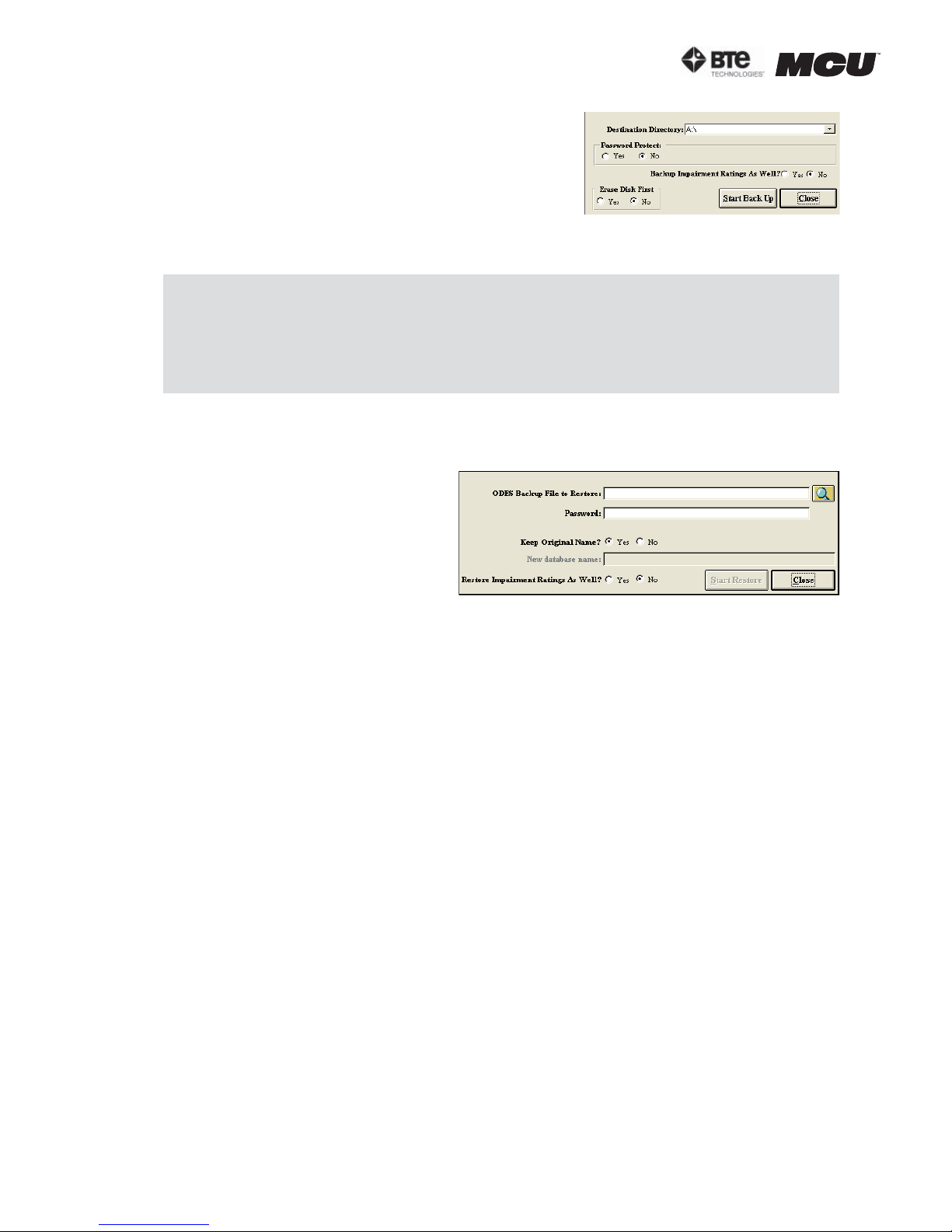
Back up a database by locating the directory you
would like to save the database to, selecting whether
or not to use a password, selecting whether or not to
back up the impairment ratings, selecting whether or
not to erase the disk, and then clicking Start Back
up.
Note that BTE Technologies cannot recover any lost or
forgotten passwords that have been used for back ups.
4. RESTORE DATABASE
This screen allows you to restore a previously backed up database (Figure 2-23).
Restore a database by locating the
directory you would like to restore
the database from, entering the
password if necessary, selecting
whether to keep the original name
or not, selecting whether to restore
the impairment ratings or not, and
then clicking Start Restore.
Figure 2-22. Back Up Database
It is highly recommended that you back up your database to a floppy disk, CD, or ZIP
disk at the end of each day. A back-up reminder can be set within the Environment
Settings Screen.
If you are using a laptop or will be transporting your computer, we recommend backing up your database prior to moving the system.
Figure 2-23. Restore Database
Note that if you choose to restore with a name that is the same as another database,
the other database will be overwritten by this new restore.
After you restore a database, you must use the Database Location field to find the
newly restored database.
5. LOG OFF AND EXIT
The Log Off option is to be used if you are going to be using ODES on and off throughout
the day. By logging off rather than exiting, the speed of ODES will be enhanced.
It is recommended you exit the program at the end of each day and shut down the computer.
B. CALIBRATION DROP-DOWN MENU
This section is covered in Section 5 - Calibration & Verification.
C. STATISTICS DROP-DOWN MENU
1. EMPLOYER INFORMATION
Provides a summary of all Employers that are stored within the Case Information section
of the ODES database. The report can be printed, exported to a snapshot file format, or
exported to Microsoft Word (if Word is installed on the computer).
2. PATIENT STATUS INFORMATION
Provides a summary of all Client Statuses. If the status of a client has been added to
the database in the Client Case page, the client will be added to this report. You may
sort by last name or by the status of the client. The report can be printed, exported to
a snapshot file format, or exported to Microsoft Word (if Word is installed on the com-
page
14
40040005 rev. 000
Page 29
section 02
puter).
3. PATIENT INFORMATION
Provides a summary of all client information that has been added to the database. The
report can be printed, exported to a snapshot file format, or exported to Microsoft Word
(if Word is installed on the computer).
4. REFERRAL INFORMATION
Provides a summary of all referral sources that have been entered into the database.
The report can be printed, exported to a snapshot file format, or exported to Microsoft
Word (if Word is installed on the computer).
5. INSURANCE INFORMATION
Provides a summary of all insurance companies that have been entered into the database. The report can be printed, exported to a snapshot file format, or exported to
Microsoft Word (if Word is installed on the computer).
6. STATISTICAL QUERIES
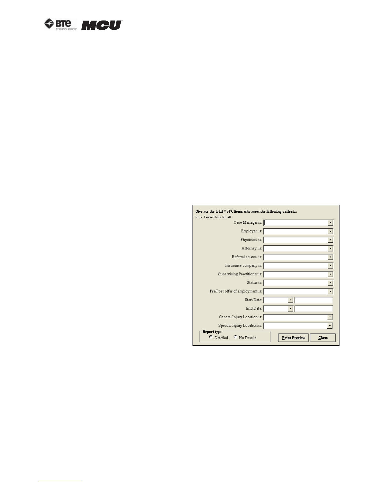
Allows you to query for information regarding existing clients by searching various criteria (Figure 2-24):
•Case Manager
•Employer
•Physician
•Attorney
•Referral Source
•Insurance Company
•Supervising Practitioner
•Status
•Pre/Post off of employment
•Start/End Date
•Injury Locations
The report provides detailed information on length of treatment, common
injuries, and the number of clients being referred from a specific source.
Under report type, select ‘Detailed’ to
obtain a list of the clients, and select
‘No Details’ to obtain the summary
without client names.
The report can be printed, exported to a snapshot file format, or exported to Microsoft
Word (if Word is installed on the computer).
7. REAL TIME ANALYSIS
Allows you to analyze the data from each individual client in detail. It also allows you to
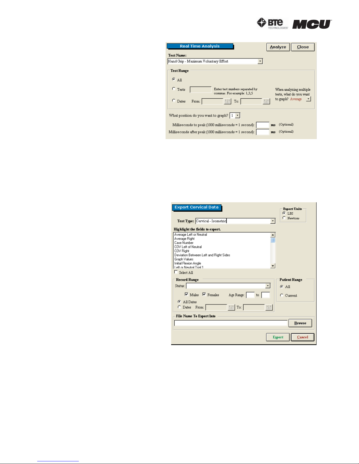
compare individual or multiple trials of any strength test that is recorded in the database. Real Time Analysis is useful for research, analyzing job demands, and client progress/tracking (Figure 2-25).
Step 1. Select the protocol to analyze.
Step 2. Select the test range.
40040005 rev. 000
Figure 2-24. Statistical Queries
page
15
Page 30
section 02
Step 3. Specify whether you wish
to analyze a specific trial or the
average of the trials relating to the
specific protocol for a specific client.
Step 4. Specify which position you
would like to graph.
Step 5. Indicate the time frame
you would like to analyze (optional).
Step 6. Click Analyze and a graph
of the real time analysis will appear.
8. EXPORT CERVICAL DATA
Allows Multi-Cervical users participating in International research with the Melbourne
Protocol to export raw data into a program outside of ODES. This allows the user to work
with the data in a spreadsheet format if so desired (Figure 2-26).
Step 1. Select the type of testing
data you wish to export.
Figure 2-25. Real TIme Analysis
Step 2. Select the fields you wish to
include when exporting.
Step 3. Specify your target population (including client status, gender,
and age range) or target dates.
Step 4. Select a file name and a
directory – your data will be saved
as a text file here.
The file name that you chose will
now be written in the ‘File Name to
Export Into’ line.
A confirmation message will appear
once the export is successful.
In order to locate the exported data,
close ODES and return to the Windows Desktop. Open the program
into which the data was exported
(e.g. Excel). Click on the Data tab,
select Import External Data and
then Import Data. Locate the text file
which was just exported, open the
file, and follow the directions given.
The exported data should now appear
in the spreadsheet.
Figure 2-26. Export Cervical Data
9. EXPORT ADMIN INFORMATION
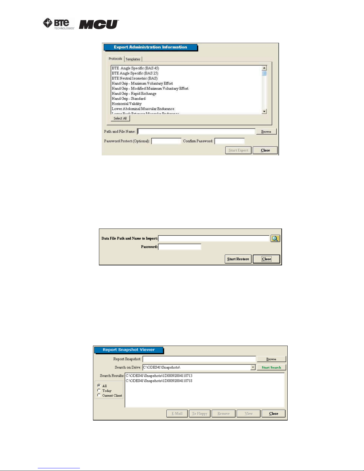
Allows you to export the administrative information related to the various protocols, super protocols, and templates (Figure 2-27).
page
16
40040005 rev. 000
Page 31
section 02
Figure 2-27. Export Administration Information
Step 1. Select which protocols, super protocols, or templates you would like to export.
Step 2. Click Browse to find the directory you would like to export into.
Step 3. Enter a password (optional) and click Start Export.
10. IMPORT ADMIN INFORMATION
Allows you to import the administrative information related to the various protocols,
super protocols, and templates (Figure 2-28).
Figure 2-28. Import Administration Information
Step 1. Locate the directory you would like to import from.
Step 2. Enter the password if needed and click Start Restore.
D. SNAPSHOTS
This screen allows you to create PDF-like files from reports so that they may be emailed
without compromising the validity of the document (Figure 2-29). A snapshot viewer executable file is bundled with the report file, which will allow individuals without ODES (e.g.
insurance companies and manufacturing plants) to view the reports.
Figure 2-29. Report Snapshot Viewer
40040005 rev. 000
page
17
Page 32

section 02
1. CREATING A SNAPSHOT
Step 1. Click on Reports within the Home Screen.
Step 2. Preview the report you would like to snapshot.
Step 3. Within the taskbar, select Export then Create a Report Snapshot.
The report will now be exported into a report snapshot, and a message will appear once
the save is successful.
2. EMAILING, SAVING, REMOVING, AND VIEWING A SNAPSHOT
Step 1. From the Home Screen taskbar, click on Snapshots.
Step 2. Locate the snapshot you wish use. Double click on the file name within the
Search Results field, and the file name should appear within the Report Snapshot text
field.
Step 3. Click on whichever operation (Email, To Floppy, Remove, or View) you would
like to perform.
If you choose to email the snapshot, a message will appear asking if you would like to
include the snapshot viewer. If the email recipient does not have ODES or has never
viewed a snapshot before, you must email the viewer. Make sure the recipient is aware
that the viewer is included with the email and it must be used to view the report.
E. FORMS DROP-DOWN MENU
This menu offers a variety of questionnaires and forms available for printing. The client
can fill out these forms and the information can be entered manually into the software.
F. UTILITIES DROP-DOWN MENU
1. STANDING/SITTING TOLERANCE REPORT
Using the standing and sitting icons within the taskbar, you can track a client’s tolerance of standing and sitting and with respective to time (Figure 2-30).
Click on either the standing or the sitting icon to begin the
timer. Once the client can no longer tolerate the chosen option, click Stop.
Figure 2-30. Standing/
Sitting Tolerance
The Standing/Sitting Tolerance Report tabulates the date and time started, the position
of the client, the duration of time the client was able to stand or sit, the total amount of
time standing or sitting, and the percentage of total standing vs. total sitting. Note that
the duration of time is rounded to the closest minute.
G. CALCULATORS DROP-DOWN MENU
1. CALCULATOR
Calculator for basic arithmetic needs
2. DEVIATION CALCULATOR
Calculator for finding the standard deviation of at least two values
H. DIGITAL CAPTURE
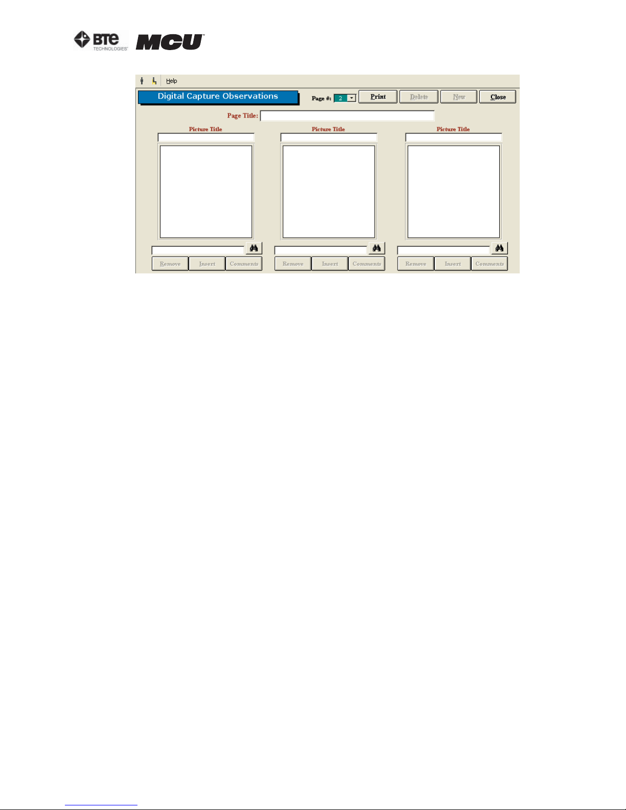
This screen allows you to insert a variety of pictures with accompanying headings and comments. This feature is useful for showing clients how to perform tasks or exercises (Figure
2-31).
page
18
40040005 rev. 000
Page 33
section 02
Figure 2-31. Digital Capture
Step 1. Take the picture with a digital camera.
Step 2. Download the picture to your hard drive using your camera software.
Step 3. Within the Digital Capture Observations screen, click on the binoculars icon to
locate the picture in the directory it was saved and click Open.
Step 4. Click Insert and the picture should appear in the large box.
Step 5. Enter a picture title and any comments if desired. The comments are included
when a page of pictures is printed.
Step 6. A picture may be removed by clicking Remove below the file name text field.
Step 7. An entire page of pictures may be printed, deleted, and created by using the Print,
Delete, and New icons at the top of the screen.
I. HELP DROP-DOWN MENU
1. HELP MANUALS
A PDF version of this MCU™ manual is located here. If you have loaded the Adobe
Acrobat Reader and the help manuals onto your hard drive, you will be able to access
the manuals directly. However, if you have no loaded software and manuals, you will be
prompted to insert the ODES CD in your disk drive. You can load Adobe Acrobat Reader
for free at www.adobe.com.
2. ABOUT
A screen showing the attributes of your specific MCU™ and ODES software. This is a
helpful screen to view whenever you need to call customer service.
40040005 rev. 000
page
19
Page 34

section 02
page
20
40040005 rev. 000
Page 35

03 - CLIENT INFORMATION
Introduction 3
Adding a Client 3
Adding a Case 4
Adding a Family Physician/Specialist/Attorney/
Referral Source/Insurance Company/Employer 4
Adding Current Medications 4
Client Photos 4
Client Status 5
Start/End Time 5
Evaluator 1 and 2 5
section 03
Adding in ICD-9 Codes 5
Areas of Complaint 5
Locking Cases 5
Finding a Client/Case 6
Adding and Removing Tests 6
40040005 rev. 000
page
1
Page 36

section 03
page
2
40040005 rev. 000
Page 37
section 03
CLIENT INFORMATION
I. INTRODUCTION
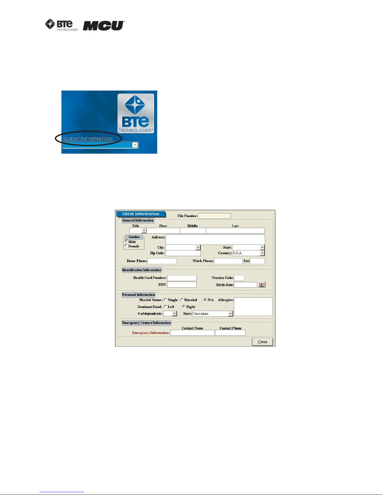
The client information screen can be accessed from the center of the home screen, just above
the client drop-down menu (Figure 3-1).
Figure 3-1. Client Information Icon
ADDING A CLIENT
In order to utilize the software, a client must first be entered. It is recommended to start by
creating a sample client in order to get familiarized with the software without having to worry
about losing valuable information (Figure 3-2).
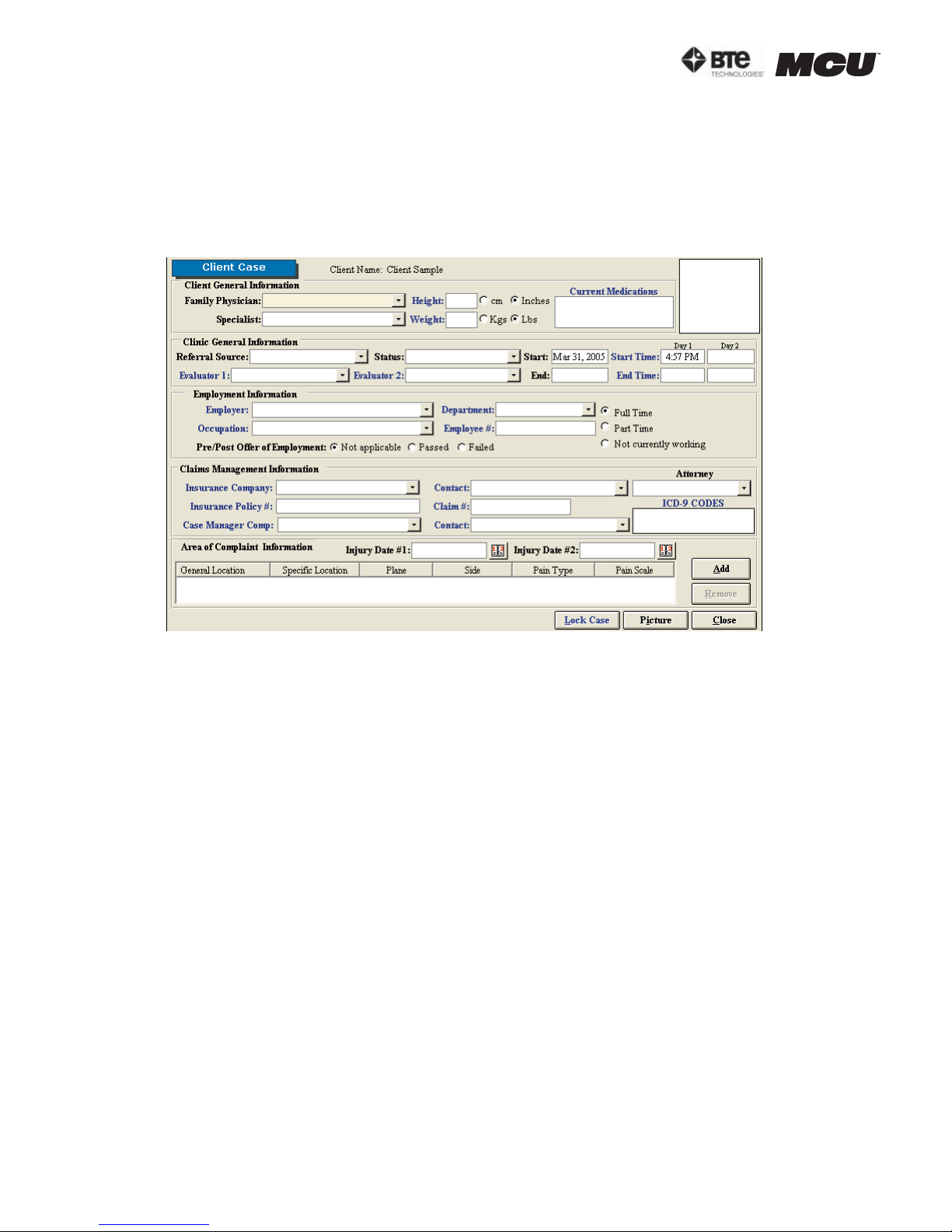
Figure 3-2. Client Information
Step 1. Click on Client Information within the Home Screen.
The Client Information screen will appear.
Step 2. Click on New Client.
Step 3. Enter all the demographics of the client.
The required information includes the name, gender, birth date, and dominant hand. This data
is required for tests which compare the client’s objective measurements with a normative database.
Step 4. Click Close once all the information is entered.
The client is now stored in the database and should appear in the drop-down menu within the
Client Information screen.
40040005 rev. 000
page
3
Page 38
section 03
III. ADDING A CASE
All clients must have a case associated with their file.
Within the Client Information screen, click New Case.
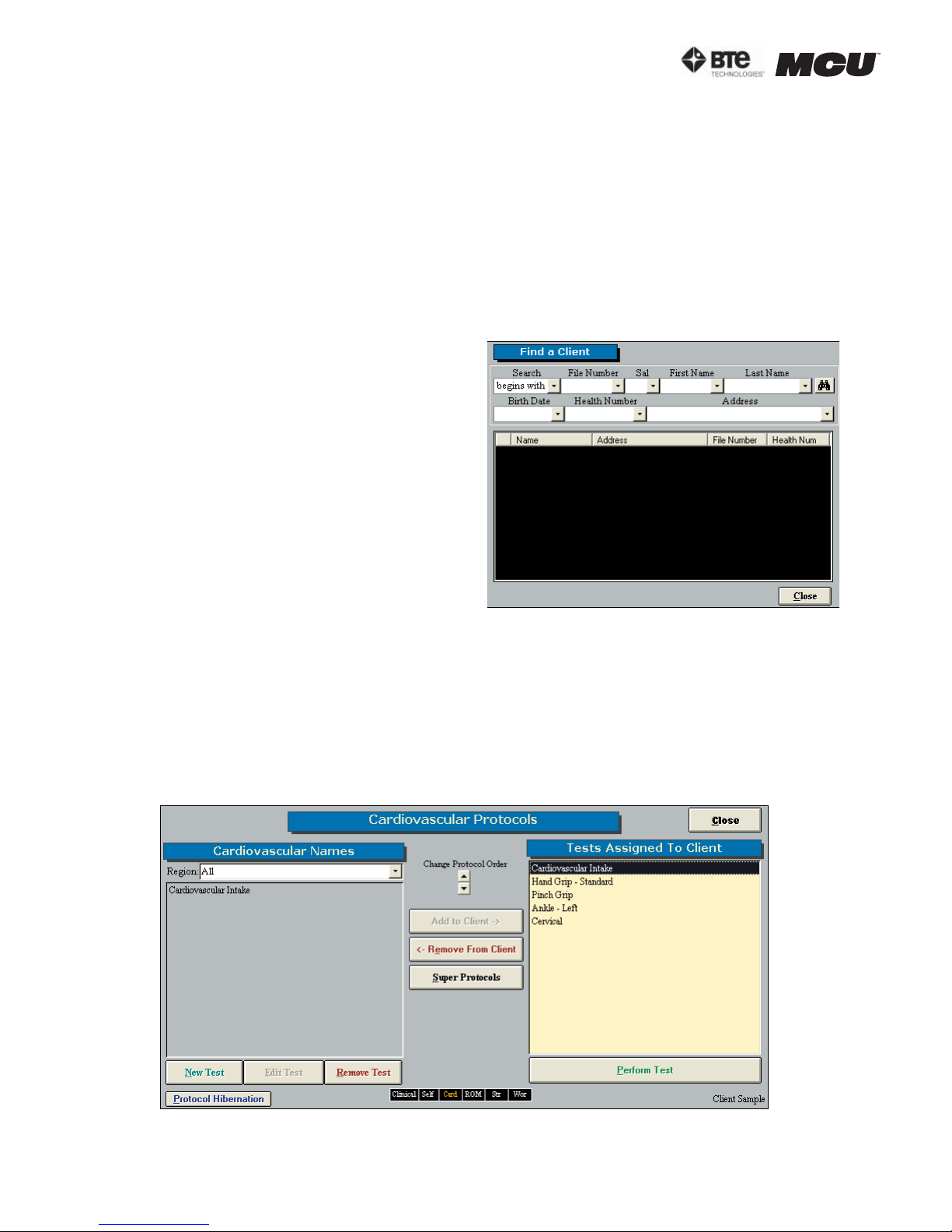
The Client Case Information screen allows you to enter information regarding the client’s physician, medications, referral sources, employment, insurance, ICD-9 codes, etc. (Figure 3-3).
Figure 3-3. Case Information
A. ADDING A FAMILY PHYSICIAN/SPECIALIST/ATTORNEY/REFERRAL SOURCE/INSURANCE COMPANY/EMPLOYER
Enter a new contact by double clicking on the white text box. A new window will appear that
allows you to add in the contact information. After entering in the information and closing
the new window, the contact’s name will appear in the drop-down menu for that particular
contact type. This data will be saved in your database so the information will only have to
be entered once.
B. ADDING CURRENT MEDICATIONS
A list of client medications can be added by double clicking in the white text box. The
Current Medications screen will appear and this allows you to enter in the name of the
medication as well as a description of its purpose and usage. If the client is taking a
medication that has previously been entered, select the name of the medication from
the drop-down menu and enter the remaining information by either typing it in or selecting it from a drop-down menu. Once all the information has been added, and the screen
is closed, the Current Medications text box will be populated with all of the medication
names.
C. CLIENT PHOTOS
This screen gives you the ability to add a client’s picture into his or her file, and this in
turn will be incorporated into that client’s reports. You must first take a picture with a
digital camera and then save the picture to your hard drive. Once that is done, click on the
large white box in the upper right hand corner of the Client Case page or click on Picture
at the bottom right hand corner of the page. Click Browse to locate the picture and then
page
4
40040005 rev. 000
Page 39

section 03
click Insert to add the photo.
D. CLIENT STATUS
The client status field is useful for keeping track of the amount and type of assessments
you have completed. Client status can also be used as a criterion under Statistical Queries. The drop-down menu should already be populated with status options, but you can
also add, edit or remove status information by double clicking on the blank text field.
E. START/END TIME
The assessment start time and date are automatically logged on the Client Case page when
you click on New Case in the Client Information Screen. In order to record an end time,
simply double click in the corresponding blank field once the assessment is completed,
and the current time will be entered into the field. You may also manually enter a time by
typing in the text field. The evaluation times will be displayed on the cover sheet of your
report.
F. EVALUATOR 1 AND 2
The Evaluator 1 and 2 fields allow the evaluator(s) to enter their name and credentials
into the Client Case page. Enter a new Evaluator by double clicking in text field. A screen
will pop up which will allow you to enter in the Evaluator’s name, designation, occupation
and registration number. This information will be included in the front of the report and
beneath the signature sign-off line (if a signature is requested when printing the report).
Please note this is not a feature of all reports printed in ODES. Click the Allow Digital
Signature checkbox if you would like to add your signature to the software; this is a useful
tool if you are anticipating e-mailing reports. See Section 2-IV-B on directions for adding a
digital signature.
G. ADDING IN ICD-9 CODES
ICD-9 codes can be stored within ODES for later use. Double click the blank ICD-9 Codes
box on the Client Case page, and a screen will pop up allowing you to select the proper
codes. To assign an existing ICD-9 code to your client, select the code from the Codes in
Database drop-down menu and click Add. Create new codes by double clicking on the ICD-9
Codes in Database field and entering in the code and description. Once an ICD-9 code has
been added to the database, it will be available from the drop-down menu for future clients. In addition, once a code is entered, it is available for use in the note templates.
H. AREAS OF COMPLAINT
A client’s areas of complaint may be obtained from his or her responses to the Pain Diagram or the Ransford Pain Diagram. To enter the information into the database, double
click on the large Area of Complaint Information box or click Add in the Area of Complaint
Information section of the Client Case page. A pain diagram will be displayed, which will
allow you to enter in location information and pain descriptions. After clicking on the diagram location where the client presents a complaint, complete the chart that is below the
body diagrams. Once you have entered all the information, click Add, and it will appear on
the Client Case page.
I. LOCKING CASES
This feature allows the evaluator to prevent other individuals from modifying a case. In
order to access a locked case, a password must be entered. Please note that it is your
responsibility to remember this password. If the password is forgotten, our technical support/customer service staff at BTE Technologies, Inc. will not be able to help you retrieve
it. Lock the case by clicking Lock Case at the bottom of the Client Case page. A screen will
40040005 rev. 000
page
5
Page 40
section 03
appear prompting you to enter and confirm a password. Click OK when you are done. Once
locked, you will see the Lock Case icon change to Unlock Case.
Once the Client Case page is complete, you may click the Close button located at the bottom
right hand corner of the page; this will bring you back to the Client Information page, and a
case number will now be associated with your client. Click the Close button in order to return
to the Home Screen. The new client will now be listed in the drop-down menu underneath the
Client Information button. To quickly access a client’s information screen, double click on the
client’s name. You can also quickly access the client’s case information by double clicking on
the case number under the client name drop-down menu.
III. FINDING A CLIENT/CASE
ODES allows you to search for a client or case
using various probes. Within the Client Information screen, click on Find a Client or Find a
Case to access these options (Figure 3-4).
You may search using any of the fields. Remember that the more fields which are selected, the
narrower the search. If you’re having trouble
finding a case or a client, try selecting only one
or two fields to broaden the search.
Once you have populated the fields you wish to
search by, click on the binoculars icon to retrieve the search results.
Open a client or case file by clicking on the
arrow button to the left of the name or case
Figure 3-4. Find a Client
number.
IV. ADDING AND REMOVING TESTS
Once you had added your client into ODES you can assign tests to the client.
From the Home Screen, click on Self Reports, Cardio, ROM Tests, Strength Tests, Work Sim
Tests, or Clinical Tests. The same basic screen appears for each icon: the box on the left lists
the tests related to the icon you selected, and the box on the right lists all the tests assigned
to the client (Figure 3-5).
Figure 3-5. Adding and Removing Tests
page
6
40040005 rev. 000
Page 41

section 03
Add a new test to the client by either highlighting the test name in the left box and clicking
Add to Client or by double clicking on the test name in the left box.
Once the test has been assigned to the client it will appear in the right box.
Change the order the tests will be completed in by highlighting the test in the right box and
use the up and down arrows under Change Protocol Order.
Perform the test assigned to a client either by highlighting the test in the right box and click-
ing on Perform Test or by double clicking on the test in the right box.
Remove a test from a client by highlight the test in the right box and clicking Remove From
Client.
You can access the other types of tests without having to go back to the Home Screen every time by clicking on the desired test-category box displayed at the bottom of the Protocol
Screen.
40040005 rev. 000
page
7
Page 42

section 03
page
8
40040005 rev. 000
Page 43

04 - TEMPLATES
Pre-Programmed Templates 3
Custom Templates 4
section 04
40040005 rev. 000
page
1
Page 44

section 04
page
2
40040005 rev. 000
Page 45
section 04
TEMPLATES
Each of the Notes pages in ODES has a template section that allows you to create any number of
templates. This feature allows you to specify which client information you would like to include on
each report and in which location. For example, the client’s name, date of injury, and injury locations could be inserted in the upper left hand corner of a report. This feature speeds up reporting
time, improves efficiency, and hence, profitability.
You can find pre-programmed templates or create your own templates within the following Home
Screen categories:
•History •X-Rays/Lab •Return to Work
•Testing Analysis •Examination •Referral
•Custom Note •Recommendations •Diagnosis
•Impairment •Progress Analysis •Cover Letter
I. PRE-PROGRAMMED TEMPLATES
To access the pre-programmed templates, click on one of the categories listed on the left side
of the Home Screen. Click on the template icon in the lower right hand corner of the screen
(Figure 4-1).
Figure 4-1. Template Icon
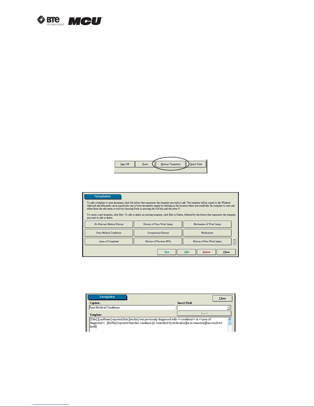
This will bring you to the main Templates screen (Figure 4-2).
Figure 4-2. Main Templates Screen
Step 1. To view or edit a template, first click on Edit; the Edit icon should change to Cancel
Edit. Next click on the pre-programmed template you wish to use.
A screen will appear with the generic template code (Figure 4-3).
Figure 4-3. Generic Template Code
Step 2. Highlight the code and either press CTRL-C on your keyboard or pull down the Edit
menu in the taskbar and select Copy. This will copy the code to your clipboard.
Step 3. Click the Close icon within the pre-programmed template’s screen. This will return you
to the main Templates screen.
40040005 rev. 000
page
3
Page 46
section 04
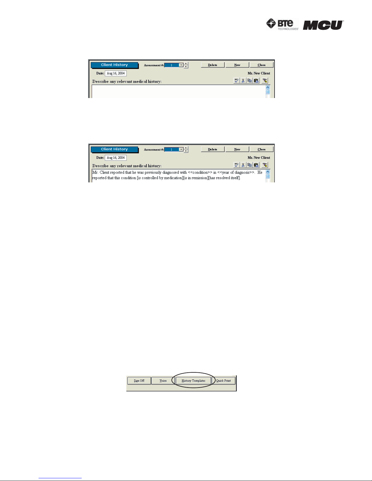
Step 4. Click Cancel Edit and then select the template you just viewed. This will bring you to
the corresponding screen (Figure 4-4).
Figure 4-4. Blank Notes Screen
Step 5. While in the home template screen, click within the white text box to place the cursor
and paste in the code. You can paste by either pressing CTRL-V on your keyboard, clicking on
the Paste icon within the home template screen, or pulling down the Edit menu in the taskbar
selecting Paste (Figure 4-5).
Figure 4-5. Updated Template Code
The code will be updated with the client’s information, but you must still populate the fields
with carets and select which bracketed options apply.
Note that any client demographics within brackets – [ ] – will automatically be populated with
the client’s information that has been entered in the client information and case screens (i.e.
title, name, gender). All other information which is bracketed but isn’t available from these
screens will remain intact until deleted. This is typically used when there are several options
to describe the situation and you must pick the most applicable one (i.e. condition is either
controlled by medication, in remission, or has resolved itself). Any text within carets – << >>
– is intended to alert the evaluator to fill in the information (i.e. name of the condition and
year of the diagnosis).
Edit a pre-programmed template by clicking Edit in the main Templates screen and selecting
the template you wish to modify. You can then add fields by selecting the desired field from the
Insert Field drop down menu and clicking Insert or delete fields using the delete key on your
keyboard. The text may also be modified as you see fit.
delete any template, first click the Delete icon in the main Templates screen; the Delete
To
icon should change to Cancel Delete. Next click on the pre-programmed template you wish to
delete.
II. CUSTOM TEMPLATES
To create or access a custom template, click on one of the categories listed on the left side of
the Home Screen. Click on the template icon in the lower right hand corner of the screen (Figure 4-5).
Figure 4-6. Template Icon
page
4
40040005 rev. 000
Page 47
section 04
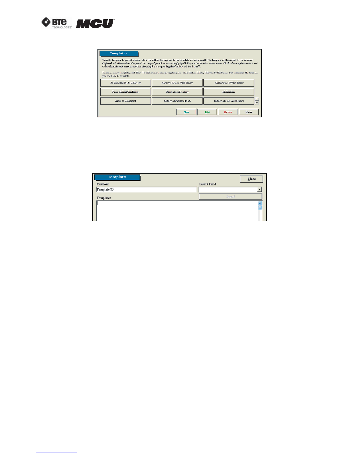
This will bring you to the main Templates screen (Figure 4-7).
Figure 4-7. Main Templates Screen
Step 1. Create a new template by clicking on New. A new icon will appear within the main
Templates screen.
Step 2. To view the template, first click on Edit; the Edit icon should change to Cancel Edit.
Next click on the template you just created.
A screen will appear with a blank text box (Figure 4-8).
Figure 4-8. Blank Template
Within this screen you can change the name of the template as well as create the generic code
by inserting fields and typing text.
Step 3. Begin by writing what you wish to include in the report, but use the merge fields when
you would like information automatically populated. The software already includes multiple
pre-programmed merge fields which are listed under the Insert Field drop down menu.
Insert a merge field by selecting the field from the Insert Field drop down menu and clicking Insert. The merge field will be inserted where the text cursor is located. The merge field
should have brackets – [ ] – around the text.
You may create your own merge fields by typing the options you would like to include and placing brackets around each one. This is useful when there are several options to describe the
situation and you must pick the most applicable one (i.e. “client arrived [early][on time][late]
for the assessment…”).
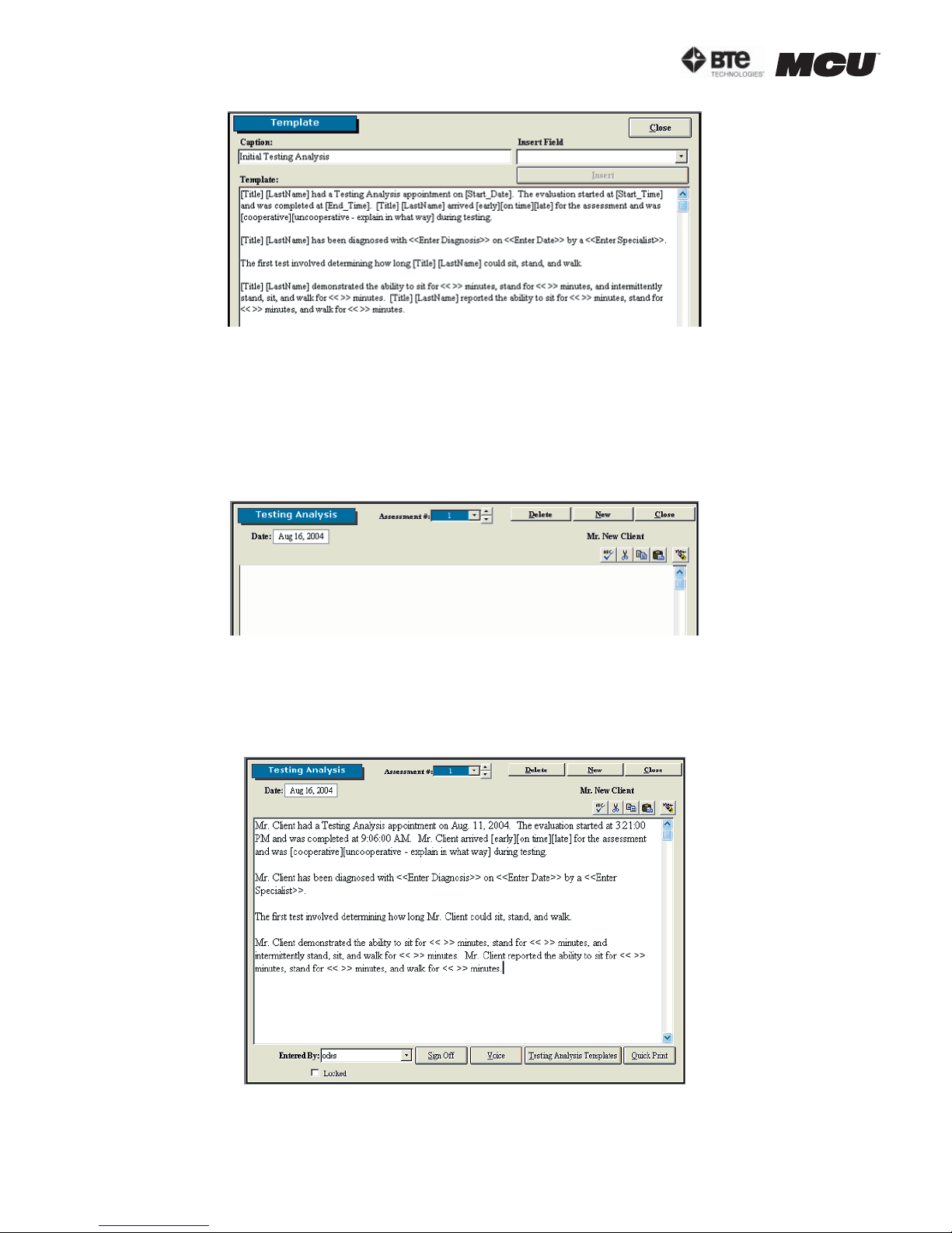
You can also include characters which alert you to personalize a field for the client. This is
useful when you need to include information which is different for every client but must be
included in the report (i.e. “client has been diagnosed with <<Enter Diagnosis>> on <<Enter
Date>> by a <<Enter Specialist>>…”). The pre-programmed templates use carets – << >> – to
bring your attention to the field, but you may use any characters you like (Figure 4-9).
40040005 rev. 000
page
5
Page 48
section 04
Figure 4-9. Custom Template Code
Step 4. Once you have finished creating the code, highlight the code and either press CTRL-C
on your keyboard or pull down the Edit menu in the taskbar and select Copy. This will copy the
code to your clipboard. Next, click the Close icon within the custom template’s screen. This
will return you to the main Templates screen.
Step 5. Click Cancel Edit and then select the template you just viewed. This will bring you to
the corresponding screen (Figure 4-10).
Figure 4-10. Blank Notes Screen
Step 6. While in the home template screen, click within the white text box to place the cursor
and paste in the code. You can paste by either pressing CTRL-V on your keyboard, clicking on
the Paste icon within the home template screen, or pulling down the Edit menu in the taskbar
and selecting Paste (Figure 4-11).
Figure 4-11. Updated Custom Template Code
The code will be updated with the client’s information, but you must still populate the fields
page
6
40040005 rev. 000
Page 49

section 04
with carets and select which bracketed options apply.
Edit a custom template by clicking Edit in the main Templates screen and selecting the tem-
plate you wish to modify. You can then add fields by selecting the desired field from the Insert
Field drop down menu and clicking Insert or delete fields using the delete key on your keyboard. The text may also be modified as you see fit.
delete any template, first click the Delete icon in the main Templates screen; the Delete
To
icon should change to Cancel Delete. Next click on the pre-programmed template you wish to
delete.
40040005 rev. 000
page
7
Page 50

section 04
page
8
40040005 rev. 000
Page 51

05 - CALIBRATION & VERIFICATION
Introduction 3
Performing the Calibration 3
Performing the Verification 7
Calibration Reports 8
section 05
40040005 rev. 000
page
1
Page 52

section 05
page
2
40040005 rev. 000
Page 53
section 05
CALIBRATION & VERIFICATION
I. INTRODUCTION
Calibration is an important component of the Multi-Cervical™ system. Since one of the main
attributes of the system is the ability to track the progress of your patients, it is essential that
the equipment is always giving accurate feedback. Therefore, we recommend calibrating every
7 days and verifying the beginning of every day.
As shown in Section 2 under the Administration Menu overview, reminders may be set for calibrations and verifications. There is also an option of requiring that the calibration and verification must be done.
II. PERFORMING THE CALIBRATION
Calibration may be performed for the head braces, halo (2 locations), and the seat.
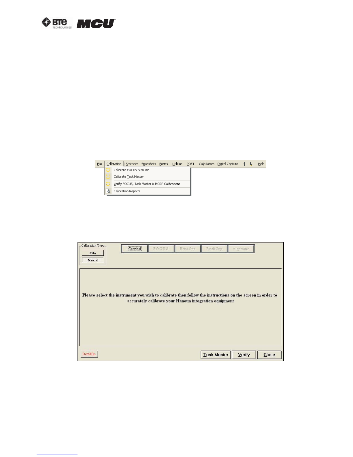
Access the Calibration Screen by selecting Calibrate FOCUS & MCRP from the Calibration
drop-down menu, which is located in the taskbar (Figure 5-1).
Figure 5-1. Calibration Drop-Down Menu
The main calibration screen will appear (Figure 5-2). Make sure that under Calibration Type,
which is located in the upper left of the screen, Manual is selected. The calibration screen
also has the Detail On feature, which allows you to directly view the voltage values of any tool
that can be calibrated; this is useful when troubleshooting.
Figure 5-2. Main Calibration Screen
40040005 rev. 000
page
3
Page 54
section 05
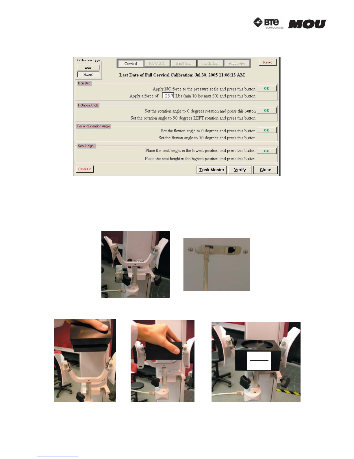
Select the Cervical icon from the main calibration screen to bring up the MCU™ calibration
screen (Figure 5-3).
Figure 5-3. Cervical Calibration Screen
The screen will always indicate the last day of successful calibration in addition to the amount
of weight used for the last calibration.
Step 1. Secure the head brace you wish to calibrate to the calibration plate. Make sure the
RJ45 cable is plugged into the head brace as well to the jack closest to the front of the unit
on the top of the MCU™ (Figure 5-4). Click the first OK on the calibration screen.
Figure 5-4. Preparing Head Brace for Calibration
Step 2. Place the calibration block on the head brace (Figure 5-5).
0.7lb
0.3kg
Figure 5-5. Placing Calibration Block on Head Brace
page
4
40040005 rev. 000
Page 55
section 05
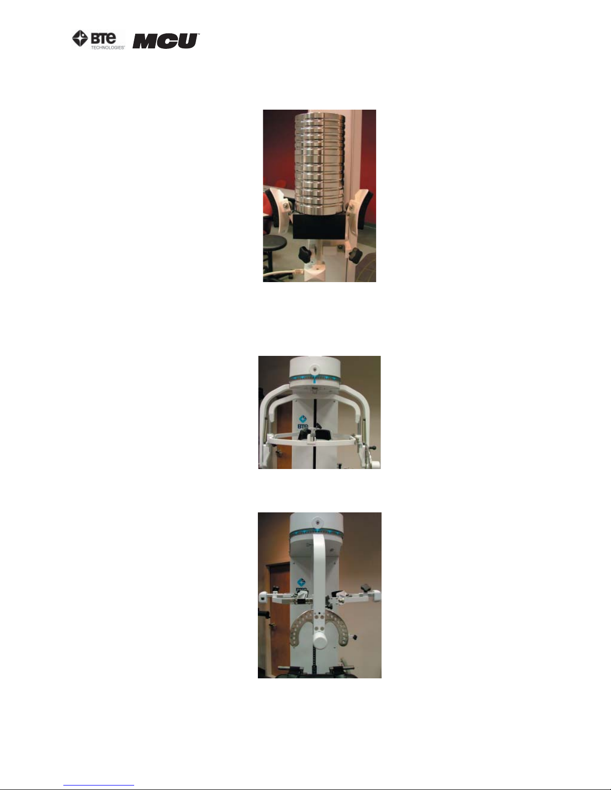
Step 3. Place the calibration weight(s) on the calibration block (Figure 5-6). Enter the amount
of weight you are using to calibrate (remember to add the weight of the calibration block,
which is 0.7lb/0.3kg) in the calibration screen and then click OK.
Figure 5-6. Calibrating the Head Brace
Step 4. Remove the calibration weights from the calibration block before proceeding with the
rest of the calibration.
Step 5. If it isn’t already, set the halo rotation to 0 degrees (Figure 5-7). Click OK on the cali-
bration screen.
Figure 5-7. Halo at 0o Rotation
Step 6. Unlock the rotation pin, set the halo rotation to 90 degrees left, and then lock the
rotation pin (Figure 5-8). Click OK on the calibration screen.
Step 7. Unlock the rotation pin, rotate the halo back to 0 degrees, and then lock the rotation
pin.
40040005 rev. 000
Figure 5-8. Halo at 90o Rotation
page
5
Page 56
section 05
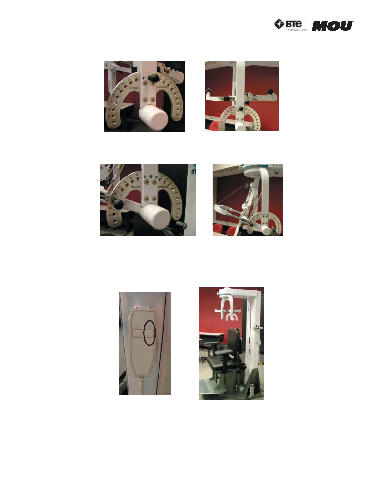
Step 8. If it isn’t already, set the halo flexion/extension angle to 0 degrees and insert the
ROM stop pin (Figure 5-9). Click OK on the calibration screen.
Figure 5-9. Halo at 0o Flexion/Extension
Step 9. Remove the ROM stop pin, set the halo flexion/extension angle to 70 degrees flexion,
and then insert the ROM stop pin (Figure 5-10). Click OK on the calibration screen.
Figure 5-10. Halo at 70o Flexion
Step 10. Remove the ROM stop pin, set the halo flexion/extension angle back to 0 degrees,
and insert the ROM stop pin.
Step 11. If it isn’t already, lower the seat height to its lowest position (Figure 5-11). Click OK
on the calibration screen.
Figure 5-11. Seat Height at Lowest Position
page
6
40040005 rev. 000
Page 57
section 05
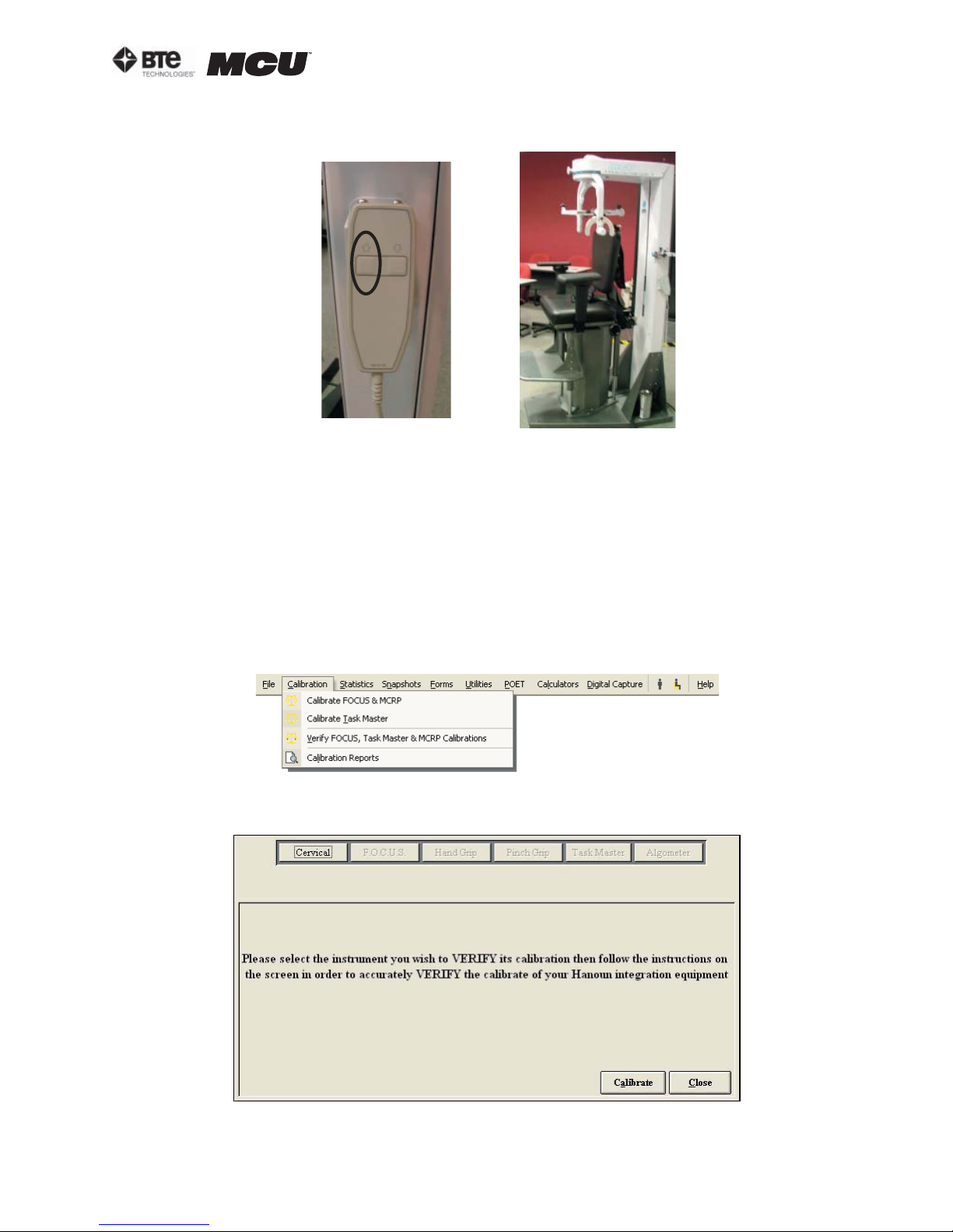
Step 12. Make sure the seat back is at its lowest position, and then raise the seat height to
its highest position (Figure 5-12). Click OK on the calibration screen.
Figure 5-12. Seat Height at Highest Position
Step 13. Once the device has been successfully calibrated, a screen will appear requesting
the name of the individual who just completed the calibration.
III. PERFORMING THE VERIFICATION
It is recommended that the accuracy of the device be verified after calibration. In addition,
verification should be completed prior to testing each day or after the equipment has been set
up.
Note that verification may only be performed on the head braces.
The Verification Screen can be accessed under the Calibration menu within the taskbar or
within the individual tool calibration screens (Figure 5-13).
Figure 5-13. Calibration Drop-Down Menu
The main verification screen will appear (Figure 5-14).
Figure 5-14. Main Verification Screen
40040005 rev. 000
page
7
Page 58
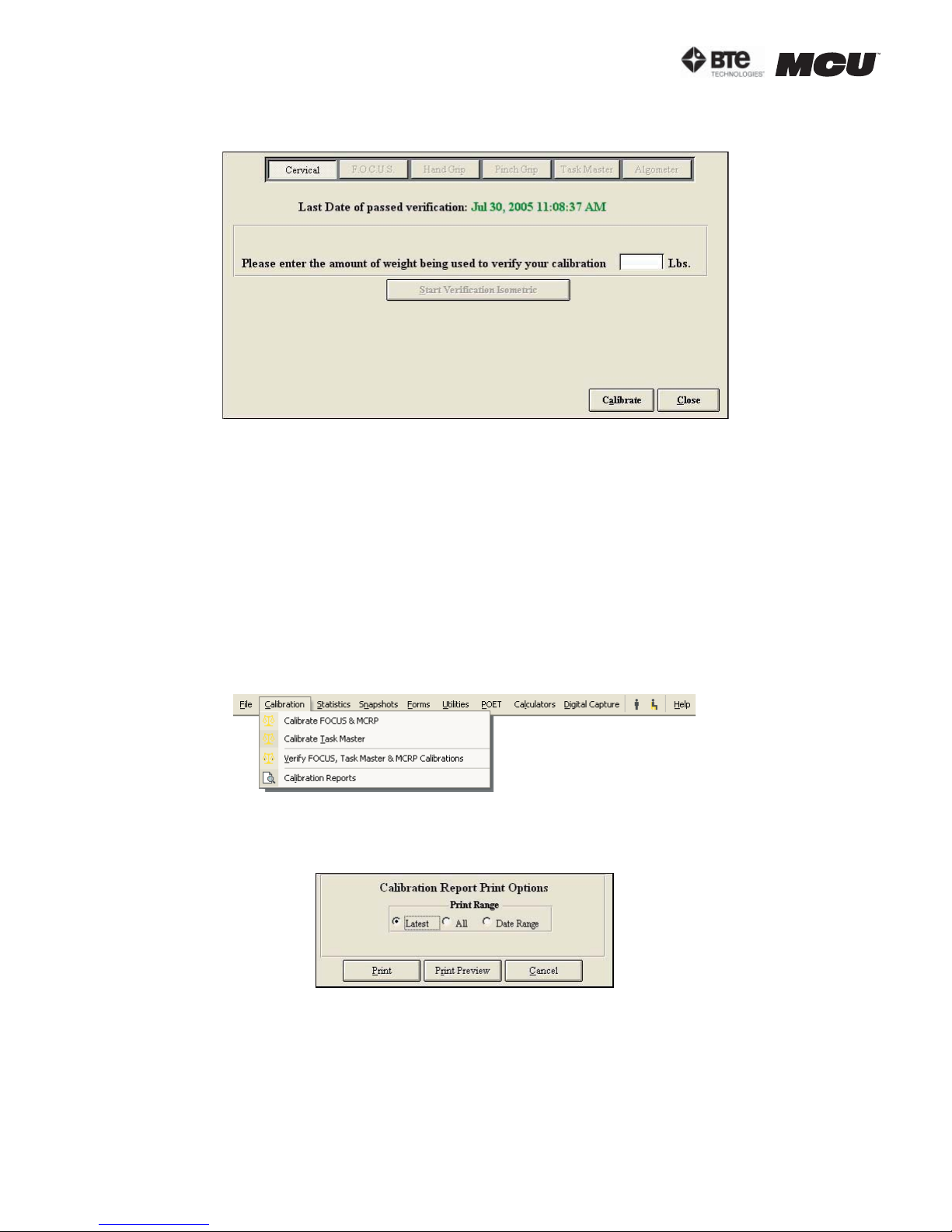
section 05
Select the Cervical icon from the main verification screen to bring up the MCU™ verification
screen (Figure 5-15).
Figure 5-15. Cervical Verification Screen
The screen will always indicate the last day of successful verification.
The verification tools and process are the same as calibration. However, you must make sure
to use a different amount of weight for the verification than you did for the calibration.
Lastly, remember to include the weight of the calibration fixture, which is 0.7lb.
Once the device has been successfully verified, a screen will appear requesting the name of
the individual who just completed the calibration. In addition, the verification screen will show
the weight that you entered compared to the weight that the software calculated.
IV. CALIBRATION REPORTS
To print or view the calibration and verification reports, go to the Calibration menu within the
taskbar and then Calibration Reports (Figure 5-16).
Figure 5-16. Calibration Drop-Down Menu
You may filter the calibration report according to latest calibration, all calibrations, or date
range (Figure 5-17).
Figure 5-17. Calibration Report Options Menu
Print a report by clicking Print.
View a report by clicking Print Preview.
page
8
40040005 rev. 000
Page 59
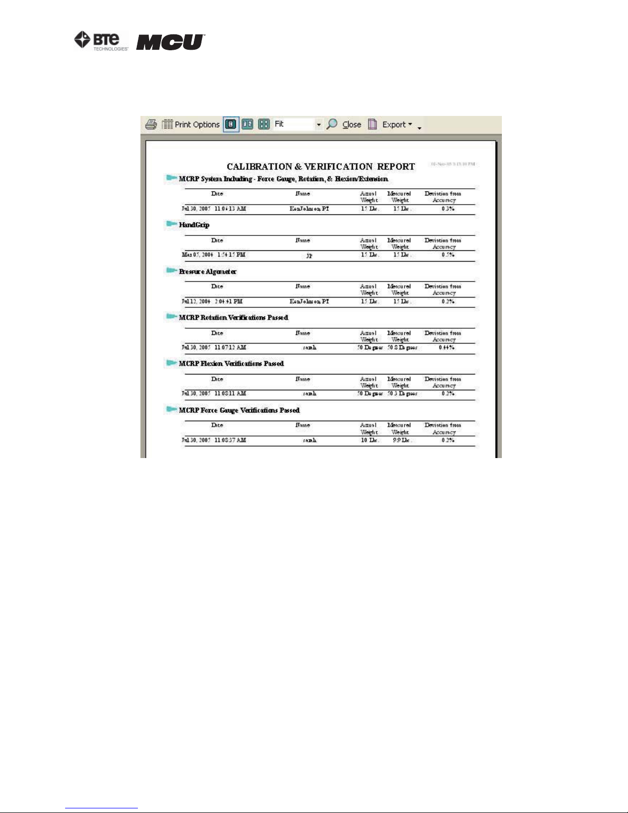
section 05
Reports include the name of the person who performed the calibration/verification, the date
when the calibration/verification occurred, and actual weight vs. measured weight, and any
deviation from the accuracy of the device (Figure 5-18).
Figure 5-18. Calibration and Verification Report
40040005 rev. 000
page
9
Page 60

section 05
page
10
40040005 rev. 000
Page 61

06 - PROTOCOLS
Self Reports 3
Utilizing Self Reports 3
Editing and Creating Self Reports 4
Cardiovascular Protocols 5
Utilizing Cardiovascular Protocols 5
Editing and Creating Cardiovascular Protocols 5
ROM Protocols 7
Positioning the Patient for a Cervical ROM Protocol 7
Positioning the Patient for a ROM Flexion or Extension Test 8
Positioning the Patient for a ROM L/R Rotation Test 9
Positioning the Patient for a ROM Lateral Flexion Test 10
section 06
Utilizing the Cervical ROM Protocol 11
Accessing the Cervical ROM Protocol 11
Utilizing the ROM Flexion Test 13
Utilizing the ROM Rotation Test 14
Utilizing the ROM Lateral Flexion Test 15
Utilizing the ROM Extension Test 17
Strength Protocols 18
Positioning the Patient for a Neutral Cervical
Isometric Strength Protocol 18
Positioning the Patient for an Isometric Flexion/Extension Test 20
Positioning the Patient for an Isometric Lateral Test 21
Positioning the Patient for a 25 Degree Cervical
Isometric Strength Protocol 22
o
Positioning the Patient for a 25
Positioning the Patient for a 25
Isometric Flexion/Extension Test 24
o
Isometric Lateral Test 25
Positioning the Patient for a 45 Degree Cervical
Isometric Strength Protocol 26
o
Positioning the Patient for a 45
Positioning the Patient for a 45
Isometric Flexion/Extension Test 28
o
Isometric Lateral Test 29
Utilizing the Cervical ROM Protocol 30
Accessing the Cervical Strength Protocols 30
Utilizing the Strength Flexion Test 31
Utilizing the Strength Extension Test 33
40040005 rev. 000
page
1
Page 62

section 06
Utilizing the Strength Lateral Test 34
Utilizing the Strength Protraction Test 36
Utilizing the Strength Retraction Test 37
Creating Custom Cervical Integration Protocols 38
Clinical Protocols 39
Utilizing Clinical Protocols 39
Editing and Creating Clinical Protocols 40
Super Protocols 41
Validity Analysis 43
page
2
40040005 rev. 000
Page 63
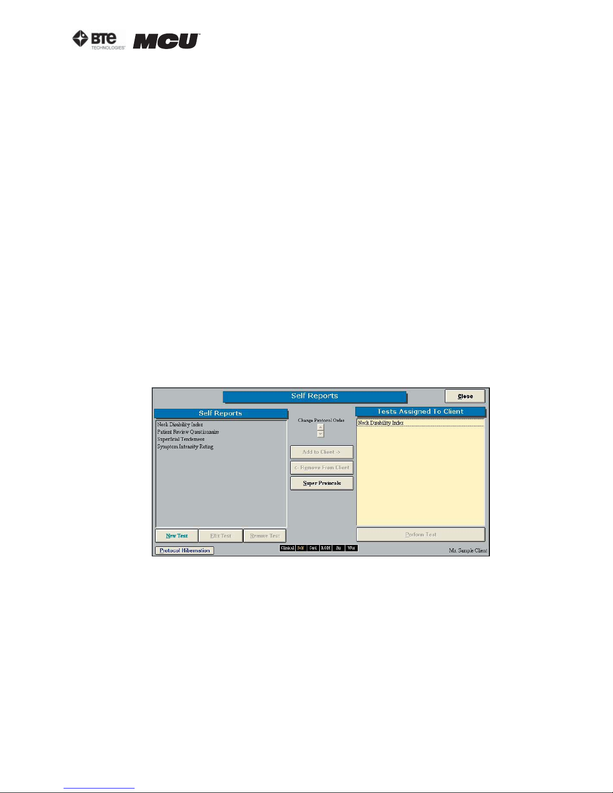
section 06
PROTOCOLS
Through the ODES software, you can access many pre-programmed protocols as well as create customized protocols. The following protocol categories can be accessed through the Home
Screen:
•Self Reports •Cardio •ROM Tests •Strength Tests •Clinical Tests
BTE Technologies recommends that the MCU™ be used in conjunction with a certified training
program on The Melbourne Protocol. This training program covers the practical and clinical application of Evaluation Protocols for patients suffering from various cervical disorders. Precautions,
indications, and contra-indications for the evaluation of patients on the MCU™ are also covered.
Refer to Section 10 for more information on this training program.
I. SELF REPORTS
ODES includes several pre-programmed Self Report protocols, which are intended to be completed without the use of any tools. These are typically questionnaires used to evaluate the
patient’s perceived level of injury and pain.
A. UTILIZING SELF REPORTS
Access the pre-programmed Self Reports protocols by clicking the Self Reports icon on the
Home Screen.
This will bring you to the Self Reports Protocols main page. From this page you have the
ability to access all the pre-programmed protocols, including those in hibernation, add and
remove tests to clients, create new range of motion tests, edit tests, and delete tests (Figure 6-1).
Figure 6-1. Self Reports Protocol Screen
Step 1. Assign a test to a client by highlighting the test in the left box and clicking Add to
Client or by double clicking on the test in the left box.
Step 2. Once a test has been assigned to a client, highlight the test name in the right box
and click Perform Test to bring up the testing screen.
Step 3. Fill out the questionnaire using the following options: a) Read the questions aloud
and enter in the answers; b) Allow the patient to enter in the answers via the computer; c)
Print out the questionnaire and allow the patient to enter in the answers on the paper.
Step 4. Store and/or file the questionnaire according to your clinic’s procedures.
40040005 rev. 000
page
3
Page 64
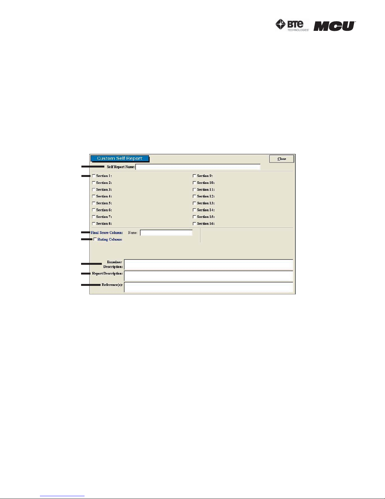
section 06
B. EDITING AND CREATING SELF REPORTS
Access the pre-programmed Self Reports protocols by clicking the Self Reports icon on the
Home Screen.
This will bring you to the Self Reports Protocols main page, where you can edit and create
tests.
Edit a test by highlighting the test you would like to edit in the left box and clicking Edit
Test.
Create a new test by clicking on New Test.
If you are editing a test, a screen will appear with the current settings of the test you
selected. If you are creating a test, a screen will appear with the same headings as if you
were editing a test, but all of the text fields will be blank (Figure 6-2).
A
B
C
D
E
F
G
Figure 6-2. Custom Self Report
Since editing and creating protocols are very similar, an example of an edited test will be
given, but the same guidelines apply for creating a test.The following can typically be edited or created on Custom Self Report Tests:
A. Test Name - Type in the name of the test
B. Section - Type in the sections to include in the test
C. Final Score Column Name - Type in the name of the final score column
D. Rating Column - Select whether to include a rating column and then type in the name of
the column
E. Examiner Description - Type in any description the examiner will need to perform the
test - this field is especially useful for supplying instructions on how to perform the evaluation
F. Report Description - Type in any description that should be included on the report
G. Reference Information - Include any reference information that needs to be added to
the report
Once the screen has been closed, the protocol is saved under the assigned test name with
page
4
40040005 rev. 000
Page 65
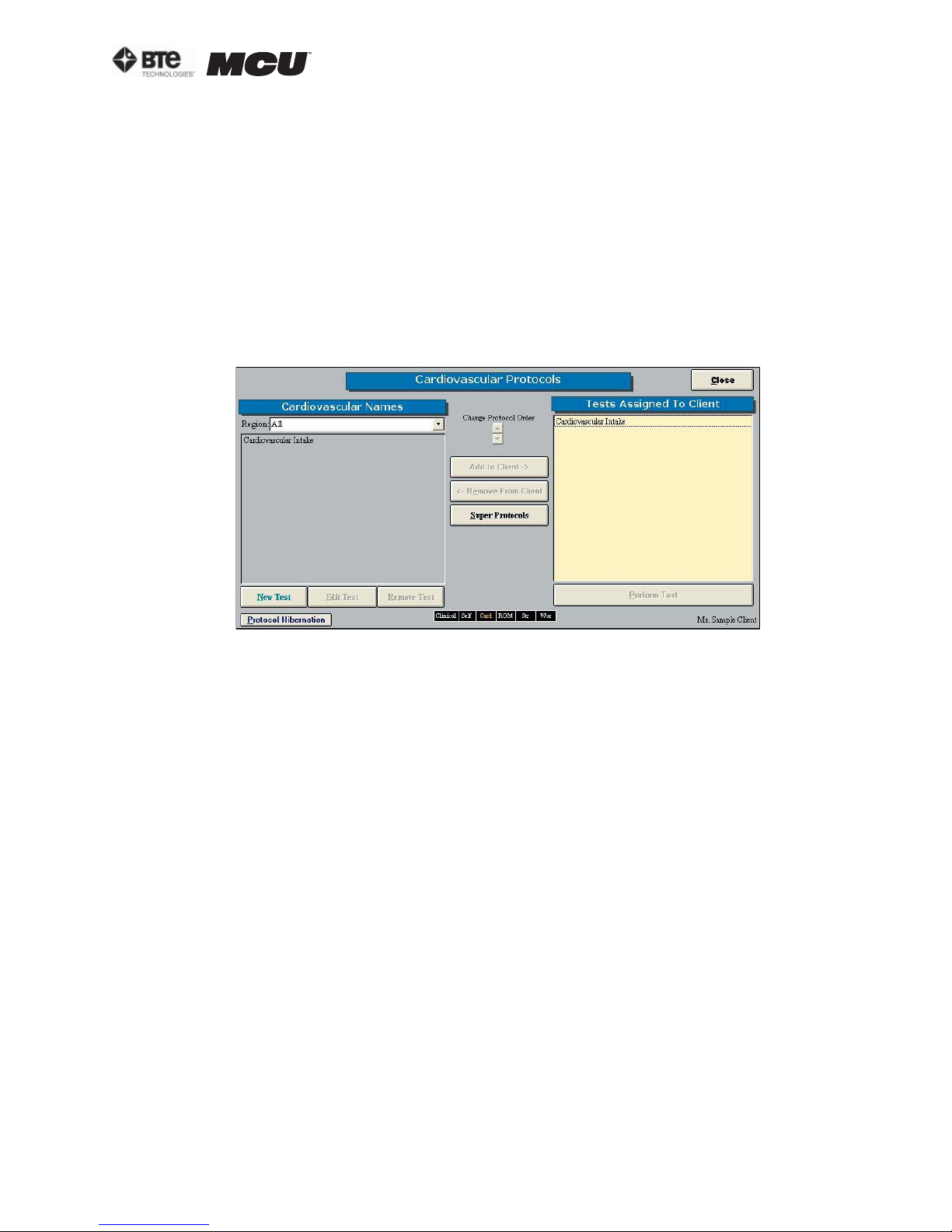
the new specifications.
II. CARDIOVASCULAR PROTOCOLS
ODES includes several pre-programmed Cardiovascular protocols.
A. UTILIZING CARDIOVASCULAR PROTOCOLS
Access the pre-programmed Cardiovascular protocols by clicking the Cardio icon on the
Home Screen.
This will bring you to the Cardiovascular Protocols main page. From this page you have the
ability to access all the pre-programmed protocols, including those in hibernation, add and
remove tests to clients, create new range of motion tests, edit tests, and delete tests (Figure 6-3).
section 06
Figure 6-3. Cardiovascular Protocols
Step 1. Assign a test to a client by highlighting the test in the left box and clicking Add to
Client or by double clicking on the test in the left box.
Step 2. Once a test has been assigned to a client, highlight the test name in the right box
and click Perform Test to bring up the testing screen.
Step 3. Follow the instructions on the test screen.
B. EDITING AND CREATING CARDIOVASCULAR PROTOCOLS
Access the pre-programmed Cardiovascular protocols by clicking the Cardio icon on the
Home Screen.
This will bring you to the Cardiovascular Protocols main page, where you can edit and create tests .
Edit a test by highlighting the test you would like to edit in the left box and clicking Edit
Test.
Create a new test by clicking on New Test.
If you are editing a test, a screen will appear with the current settings of the test you
selected. If you are creating a test, a screen will appear with the same headings as if you
were editing a test, but all of the text fields will be blank (Figure 6-4).
40040005 rev. 000
page
5
Page 66
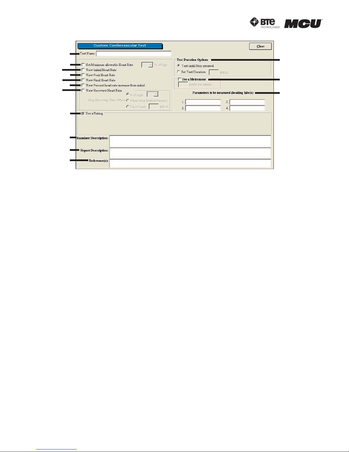
section 06
A
B
C
D
E
F
G
H
I
J
K
Since editing and creating protocols are very similar, an example of an edited test will be
given, but the same guidelines apply for creating a test.
L
M
N
Figure 6-4. Custom Cardiovascular Protocol
The following can typically be edited or created on Cardiovascular Tests:
A. Test Name - Type in the name of the test
B. Set Maximum Allowable Heart Rate - Select whether to set the maximum allowable
heart rate and at what percentage of age.
C. View Initial Heart Rate - Select whether to view the initial heart rate within the test
screen
D. View Peak Heart Rate - Select whether to view the peak heart rate within the test
screen
E. View Final Heart Rate - Select whether to view the final heart rate within the test
screen
F. View Percent Heart Rate Increase from Initial - Select whether to view the percent
heart rate increase from the initial within the test screen
G. View Recovery Heart Rate - Select whether to view the recovery heart rate within the
test screen and choose when to stop the recovery time
H. Use a Rating - Select whether to use a rating and then set the rating
I. Examiner Description - Type in any description the examiner will need to perform the
test - this field is especially useful for supplying instructions on how to perform the evaluation
J. Report Description - Type in any description that should be included on the report
K. Reference Information - Include any reference information that needs to be added to
the report
L. Test Duration Options - Choose which method will determine test duration
M. Use a Metronome - Select whether to use a metronome and number of beats per minute
page
6
40040005 rev. 000
Page 67
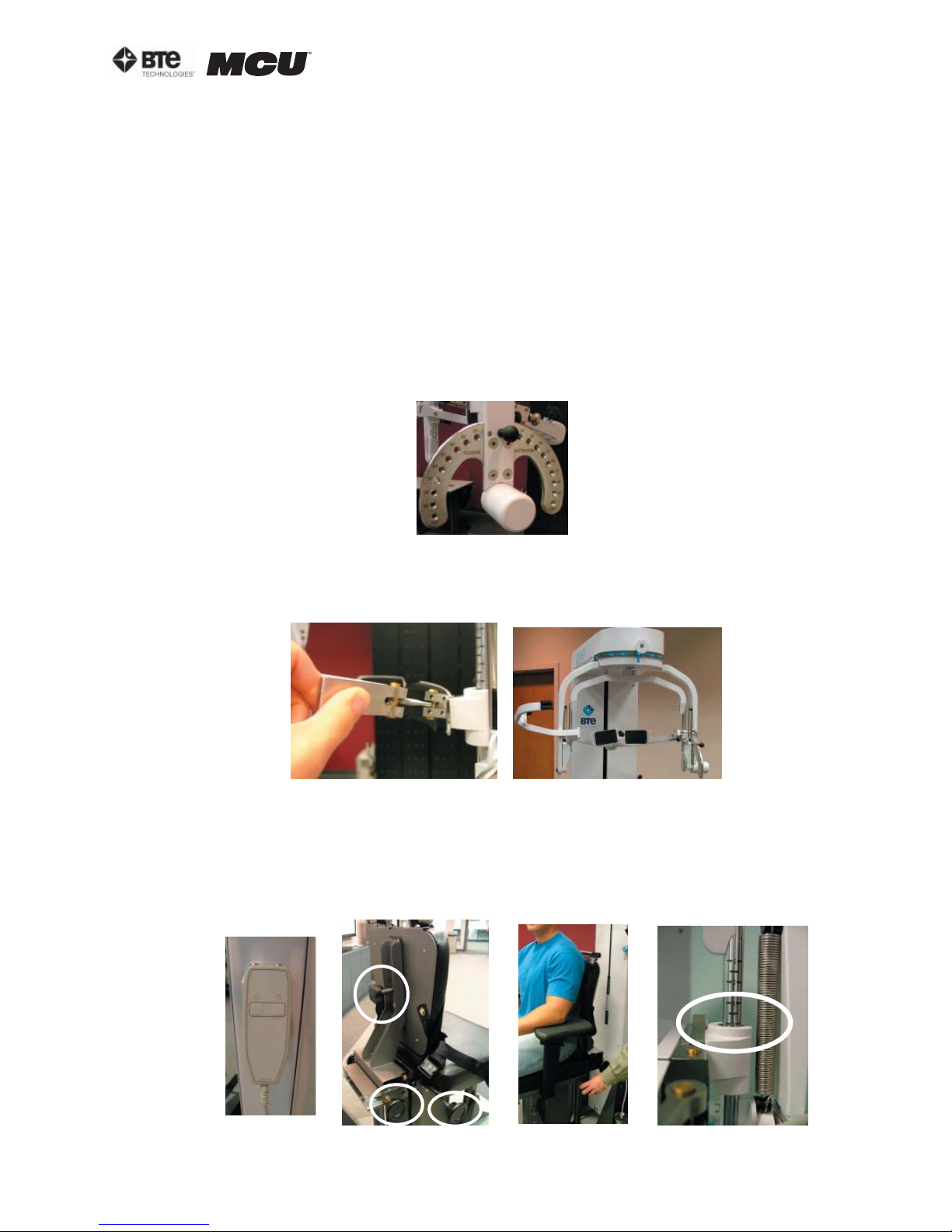
N. Parameters to be Measured (Heading Labels) - Type in the parameters that will be measured
Once the screen has been closed, the protocol is saved under the assigned test name with
the new specifications.
III. CERVICAL RANGE OF MOTION (ROM) PROTOCOLS
A. POSITIONING THE PATIENT FOR A CERVICAL ROM PROTOCOL
In order to prepare for cervical range of motion testing, it is extremely important to understand how to properly position the patient; this will prevent any injury during testing.
The following 7 steps are required prior to each type of ROM testing. Outlined after these 7
initial steps are the subsequent steps, which vary according to the test being performed.
Step 1. Insert the range-of-motion stop pin in the zero degree position on the halo (Figure
6-5).
section 06
Figure 6-5. Insert
ROM Stop
Step 2. Lower the chair all the way down to its lowest position.
Step 3. Using the latch on the right side, open the halo (Figure 6-6).
Figure 6-6. Open Halo
Step 4. Ask the patient to sit in the chair.
Step 5. Adjust the height of the seat, the position of the seat, the position of the back
of the chair, the height of the back of the chair, and the arm rests to accommodate the
patient’s size, height, and posture. Set the halo height to 3 as a starting position (Figure
6-7).
Figure 6-7. Seat Adjustments
40040005 rev. 000
page
7
Page 68
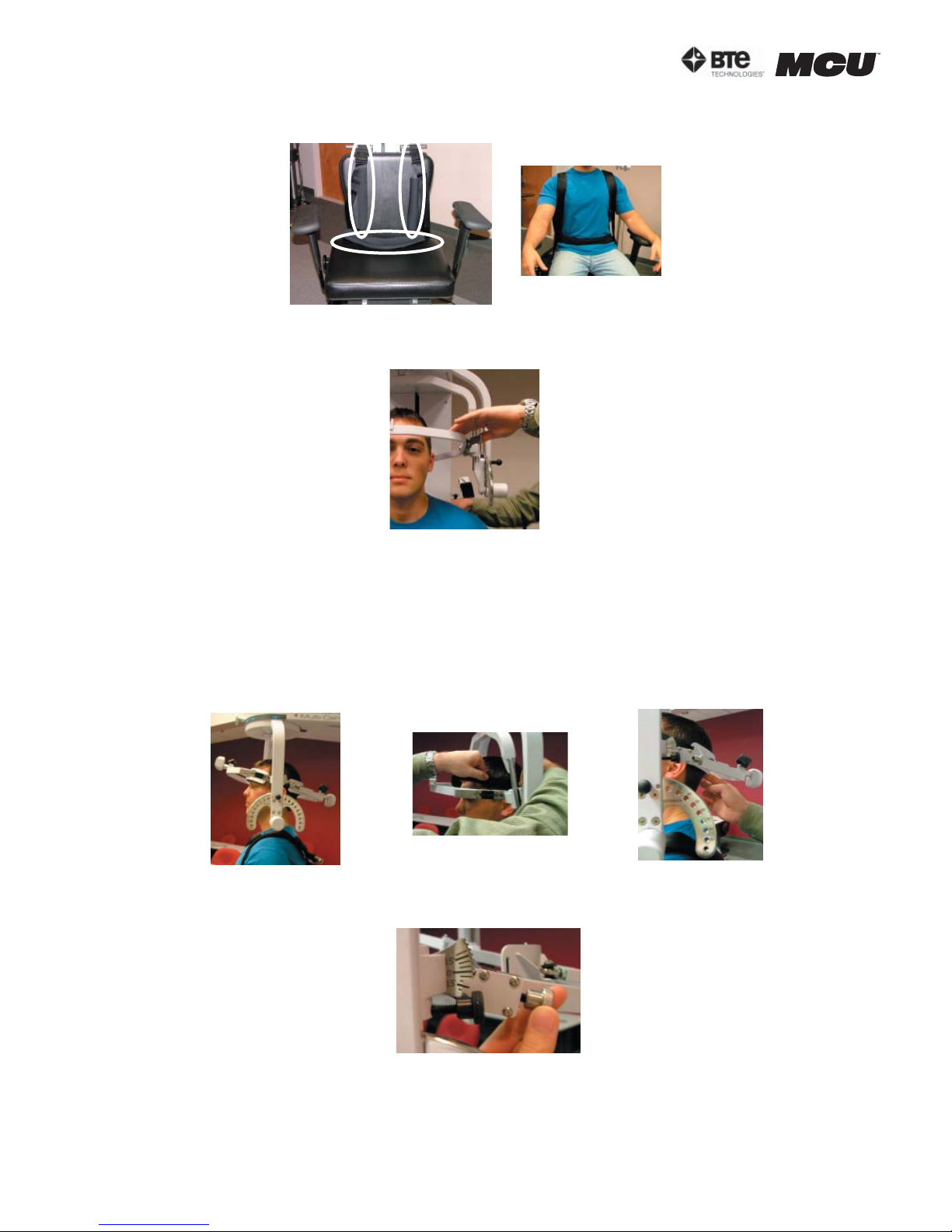
section 06
Step 6. Secure the patient with the waist strap and shoulder straps (Figure 6-8).
Step 7. Close and lock the halo (Figure 6-9).
Figure 6-8. Waist and Shoulder Straps
Figure 6-9. Close
and Lock the Halo
1. POSITIONING THE PATIENT FOR A ROM FLEXION OR EXTENSION TEST
Step 8. For a flexion test, insert both of the head braces in the halo. For an extension
test, insert the back head brace with a Velcro strap attached. Note that the bottom of
the back brace is located at the external occipital protuberance (Figure 6-10).
Location of
Flexion Set-up
Attaching Strap
Back Brace
for Extension
Figure 6-10. Initial ROM Flexion & Extension Set-ups
Step 9. Set the halo to 15 degrees below the horizontal (Figure 6-11).
Step 10. Position the head brace(s) against the patient’s head, but do not secure his/
her head in place.
Step 11. Make fine adjustments to the seat and halo such that C5/C6 of the patient’s
page
8
Figure 6-11. Halo Angle
40040005 rev. 000
Page 69
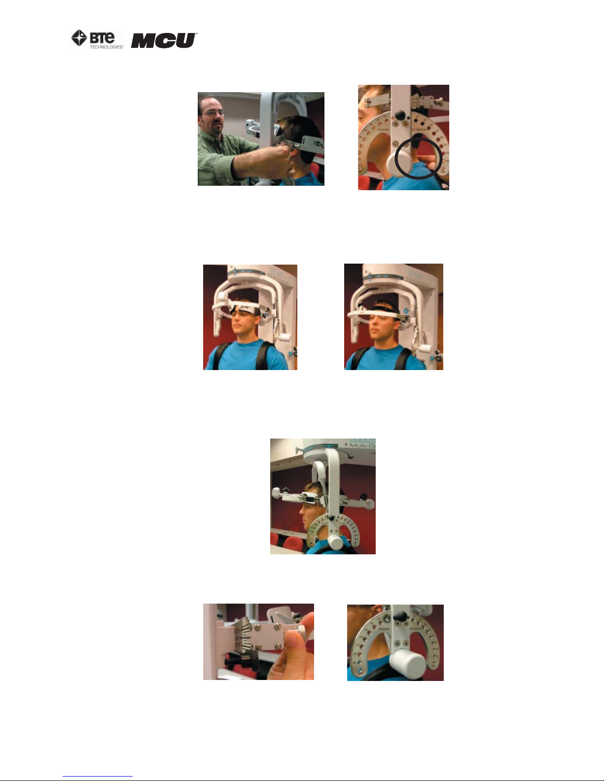
section 06
spine lines up with the pivot point of the halo (Figure 6-12).
Figure 6-12. Final Adjustments and Locating C5/C6
Step 12. Firmly secure the patient’s head with the head brace(s) and Velcro strap (if
performing an extension test).
Step 13. Remove the range-of-motion stop pin before performing the test (Figure 6-13).
Flexion
Extension
Figure 6-13. Final Set-ups for ROM Flexion & Extension
Note that the RJ45 cable is not required for this test.
2. POSITIONING THE PATIENT FOR A ROM L/R ROTATION TEST
Step 8. Insert both of the head braces in the halo (Figure 6-14).
Figure 6-14. Insert
Both Head Braces
Step 9. Set the halo to 0 degrees with respect to the horizontal and 10 degrees flexion
(Figure 6-15).
Figure 6-15. Set halo angles
Step 10. Position the head braces against the patient’s head, but do not secure his/her
head in place.
40040005 rev. 000
page
9
Page 70
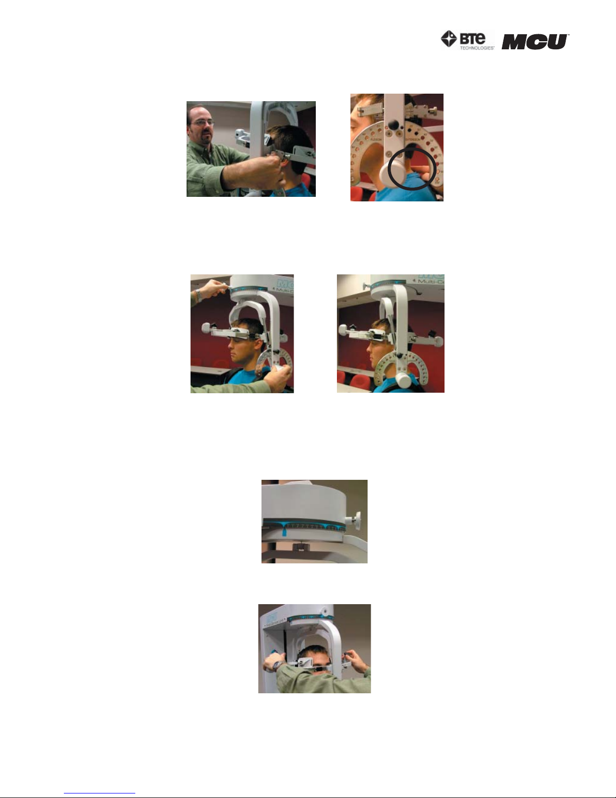
section 06
Step 11. Make fine adjustments to the seat to line up C5/C6 of the patient’s spine with
the pivot point of the halo (Figure 6-16).
Step 12. Firmly secure the patient’s head with the head braces.
Step 13. While holding onto the side of the halo, unlock the rotation pin, which is locat-
ed at the top middle of the halo, before performing the test (Figure 6-17).
Figure 6-16. Final Adjustments and Locating C5/C6
Unlock Rotation Pin
Final Rotation Set-up
Figure 6-17. Unlocking Rotation Pin and Final
ROM L/R Rotation Set-up
Note that the RJ45 cable is not required for this test.
3. POSITIONING THE PATIENT FOR A ROM LATERAL FLEXION TEST
Step 8. Unlock the rotation pin and rotate the halo to 90 degrees right rotation. Lock
the rotation pin back into place (Figure 6-18).
Figure 6-18. Halo at 90o Rotation
Step 9. Insert both of the head braces in the halo (Figure 6-19).
Step 10. Set the halo to 0 degrees with respect to the horizontal. Make sure the flexion/
extension angle is set to 0 degrees as well (Figure 6-20).
page
10
Figure 6-19. Attach Head Braces
40040005 rev. 000
Page 71
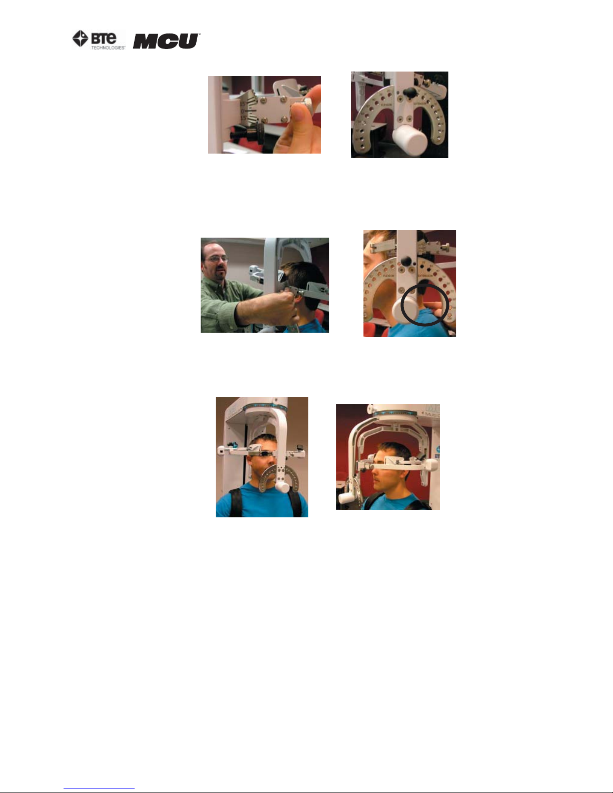
section 06
Figure 6-20. Set halo angles
Step 11. Position the head braces against the patient’s head, but do not secure his/her
head in place.
Step 12. Make fine adjustments to the seat to line up C5/C6 of the patient’s spine with
the pivot point of the halo (Figure 6-21).
Figure 6-21. Final Adjustments and Locating C5/C6
Step 13. Firmly secure the patient’s head with the head braces.
Step 14. Remove the range-of-motion stop pin before performing the test (Figure 6-22).
Figure 6-22. Final Set-up for ROM Lateral Flexion
Note that the RJ45 cable is not required for this test.
B. UTILIZING THE CERVICAL RANGE OF MOTION (ROM) PROTOCOL
1. ACCESSING THE CERVICAL ROM PROTOCOL
Access the pre-programmed ROM protocols by clicking the ROM Tests icon on the Home
Screen.
This will bring you to the ROM Protocols main page. From this page you have the ability to access all the pre-programmed protocols, including those in hibernation, add and
remove tests to clients, create new range of motion tests, edit tests, and delete tests.
Note that the Cervical Range of Motion protocol is the only pre-programmed ROM test
that will be needed for the MCU™ (Figure 6-23).
40040005 rev. 000
page
11
Page 72
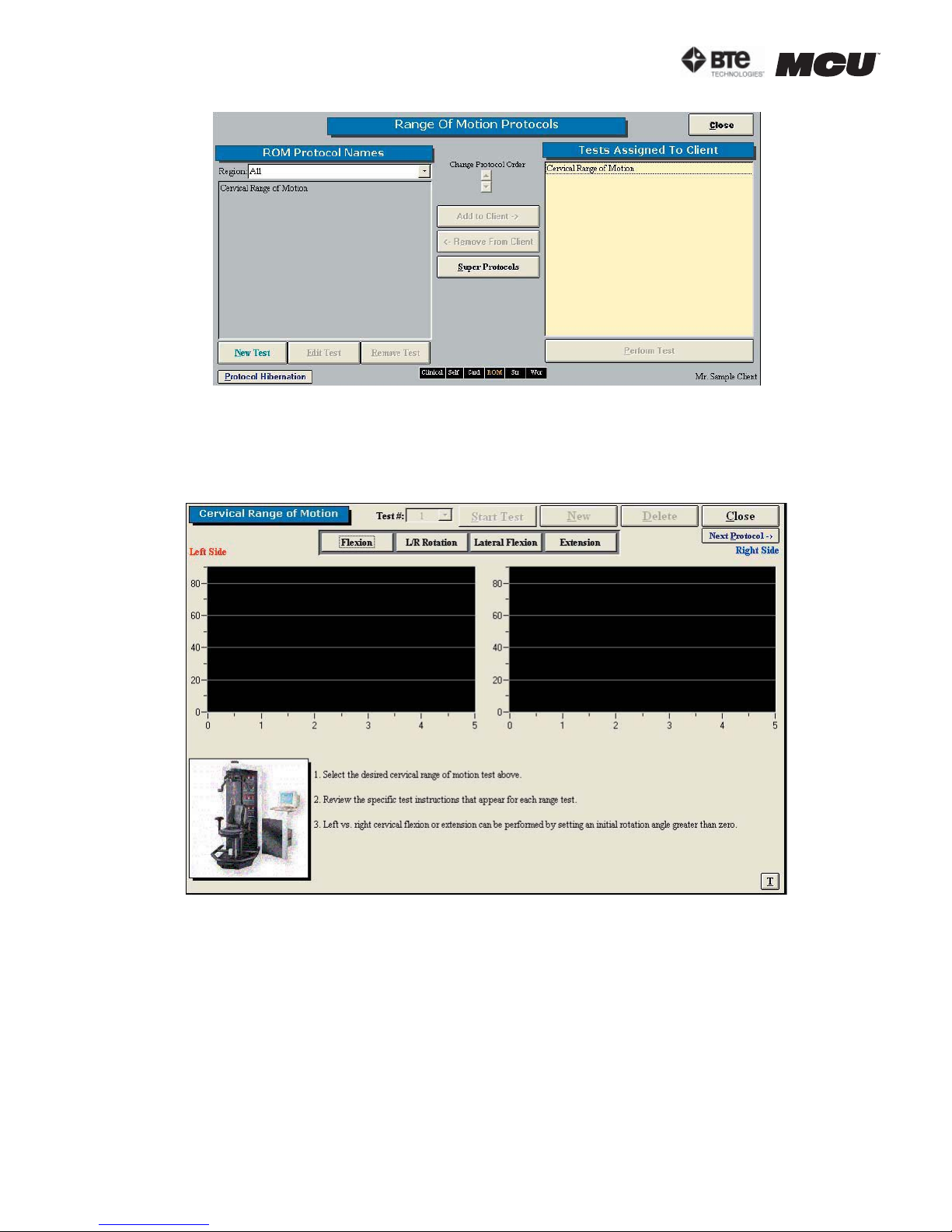
section 06
Step 1. Assign a test to a client by highlighting the test in the left box and clicking Add
to Client or by double clicking on the test in the left box.
Step 2. Once a test has been assigned to a client, highlight the test name in the right
box and click Perform Test to bring up the testing screen (Figure 6-24).
Figure 6-23. Range of Motion Protocols
Figure 6-24. Cervical Range of Motion Main Screen
The initial Cervical Range of Motion protocol screen contains the following features:
• Name of the test
• Test number
• Start Test icon, which changes to Stop Test after the test has begun
• New icon to begin a new set of tests
• Delete icon to delete the selected test’s results
• Close icon to return to the protocol screen
• Next Protocol icon to move on to the next protocol
• Flexion icon, which switches to the Flexion test screen
• L/R Rotation icon, which switches to the Rotation test screen
page
12
40040005 rev. 000
Page 73
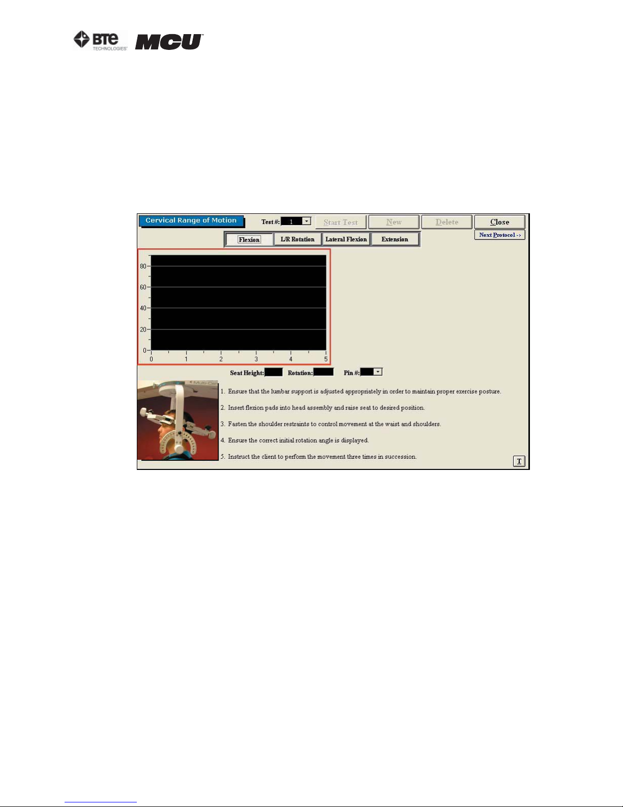
section 06
• Lateral Flexion icon, which switches to the Lateral Flexion test screen
• Extension icon, which switches to the Extension test screen
• Graphs and tables to illustrate the test results
• Instructions on how to perform the tests
• Threshold icon, which allows a threshold force to be set
2. UTILIZING THE ROM FLEXION TEST
The ROM Flexion test measures the patient’s range of motion with respect to the flexor
muscle group.
Step 1. Select the Flexion icon. The Flexion Testing screen will appear (Figure 6-25).
Figure 6-25. Cervical ROM - Flexion Test
Note that the screen shown in the figure may differ from that on the computer.
Step 2. Position the patient as described in Section 06-III of this manual.
Step 3. Click Start Test to begin testing.
Step 4. Once the test is completed, a pain scale will appear. Ask the patient to rate
his/her pain on a ten-point scale (0 is equivalent to no pain and 10 is equivalent to the
worst pain possible). Click on the number the patient stated and then click OK.
The ROM Flexion test calls for three trials to be performed.
As the protocol is performed, the screen will display the results and averages via a line
graph, table, pie chart, and bar graph.
In addition to the test results, the screen will tabulate: the average ROM, peak ROM,
coefficient of variation (COV), and the percent of normal. The pain rating determined by
the patient will also appear in the pain scale text field (Figure 6-26).
40040005 rev. 000
page
13
Page 74
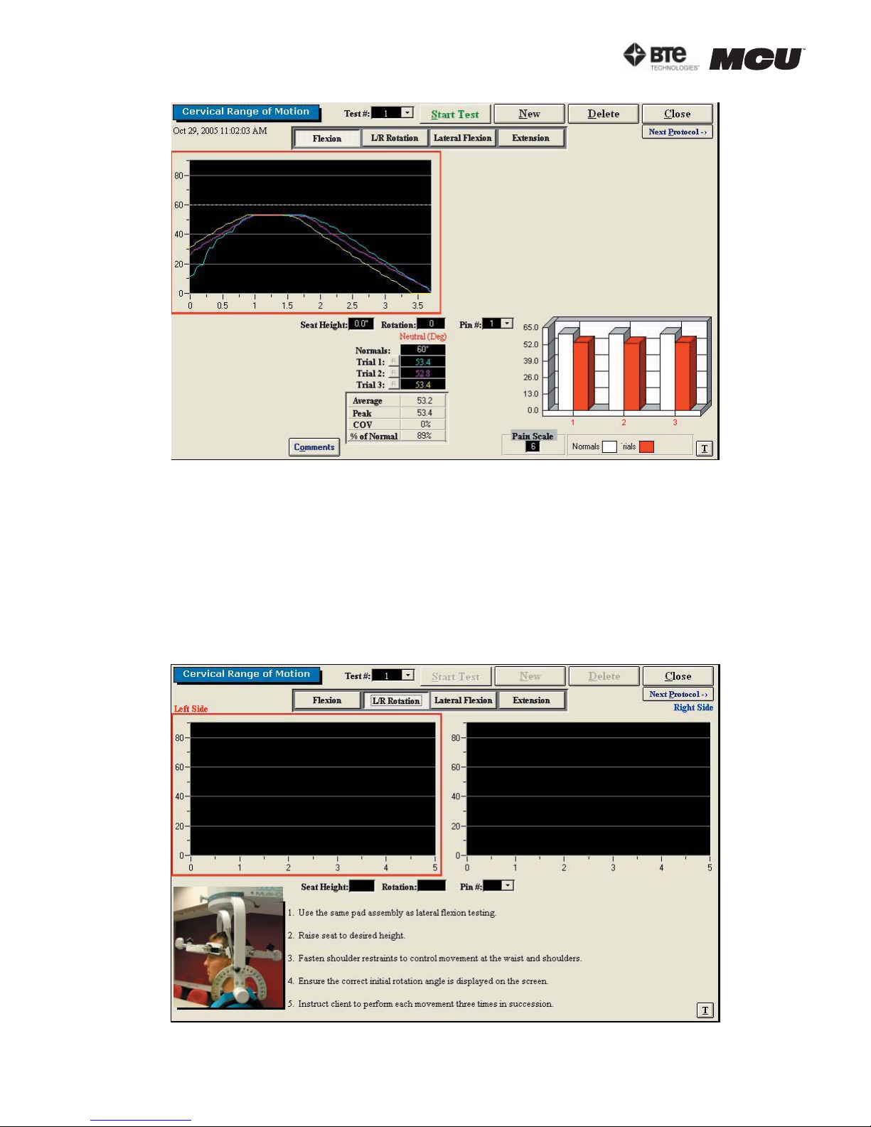
section 06
Figure 6-26. Cervical ROM - Completed Flexion Test
You may retest a trial by clicking on the R icon to the left or right of the trial table, depending on which trial you would like to redo. However, once a test has been closed, the
trials can not be retested.
3. UTILIZING THE ROM ROTATION TEST
The ROM Rotation test measures the patient’s range of motion with respect to the lateral rotator muscle group.
Step 1. Select the L/R Rotation icon. The Rotation Testing screen will appear (Figure
6-27). Note that the screen shown in the figure may differ from that on the computer.
Figure 6-27. Cervical ROM - L/R Rotation Test
page
14
40040005 rev. 000
Page 75
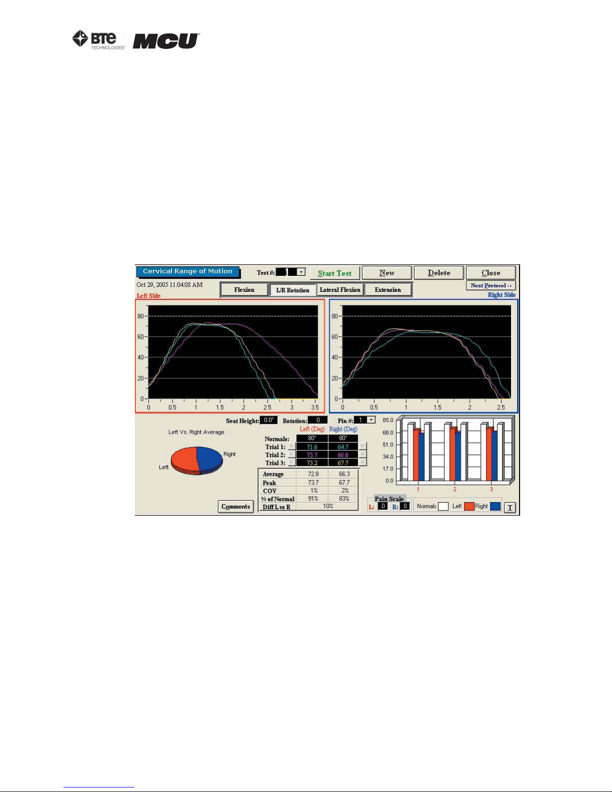
section 06
Step 2. Position the patient as described in Section 06-III of this manual.
Step 3. Click Start Test to begin testing.
Step 4. Once each side is completed, a pain scale will appear. Ask the patient to rate
his/her pain on a ten-point scale (0 is equivalent to no pain and 10 is equivalent to the
worst pain possible). Click on the number the patient stated and then click OK.
The ROM Rotation test calls for three trials to be performed per side.
As the protocol is performed, the screen will display the results and averages via a line
graph, table, pie chart, and bar graph. These figures are especially helpful in comparing
the abilities of each side.
In addition to the test results, the screen will tabulate: the average ROM, peak ROM, coefficient of variation (COV), the percent of normal, and the percent difference between
the left and right side. The pain ratings determined by the patient will also appear in
the pain scale text fields (Figure 6-28).
Figure 6-28. Cervical ROM - Completed L/R Rotation Test
You may retest a trial by clicking on the R icon to the left or right of the trial table, depending on which trial you would like to redo. However, once a test has been closed, the
trials can not be retested.
4. UTILIZING THE ROM LATERAL FLEXION TEST
The ROM Lateral Flexion test measures the patient’s range of motion with respect to the
lateral flexor muscle group.
Step 1. Select the Lateral Flexion icon. The Lateral Flexion Testing screen will appear
(Figure 6-29). Note that the screen shown in the figure may differ from that on the computer.
40040005 rev. 000
page
15
Page 76
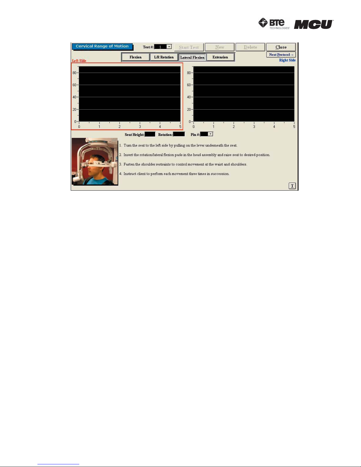
section 06
Figure 6-29. Cervical ROM - Lateral Flexion Test
Step 2. Position the patient as described in Section 06-III of this manual.
Step 3. Click Start Test to begin testing.
Step 4. Once each side is completed, a pain scale will appear. Ask the patient to rate
his/her pain on a ten-point scale (0 is equivalent to no pain and 10 is equivalent to the
worst pain possible). Click on the number the patient stated and then click OK.
The ROM Lateral Flexion test calls for three trials to be performed per side.
As the protocol is performed, the screen will display the results and averages via a line
graph, table, pie chart, and bar graph. These figures are especially helpful in comparing
the abilities of each side.
In addition to the test results, the screen will tabulate: the average ROM, peak ROM, coefficient of variation (COV), the percent of normal, and the percent difference between
the left and right side. The pain ratings determined by the patient will also appear in
the pain scale text fields (Figure 6-30).
page
16
40040005 rev. 000
Page 77
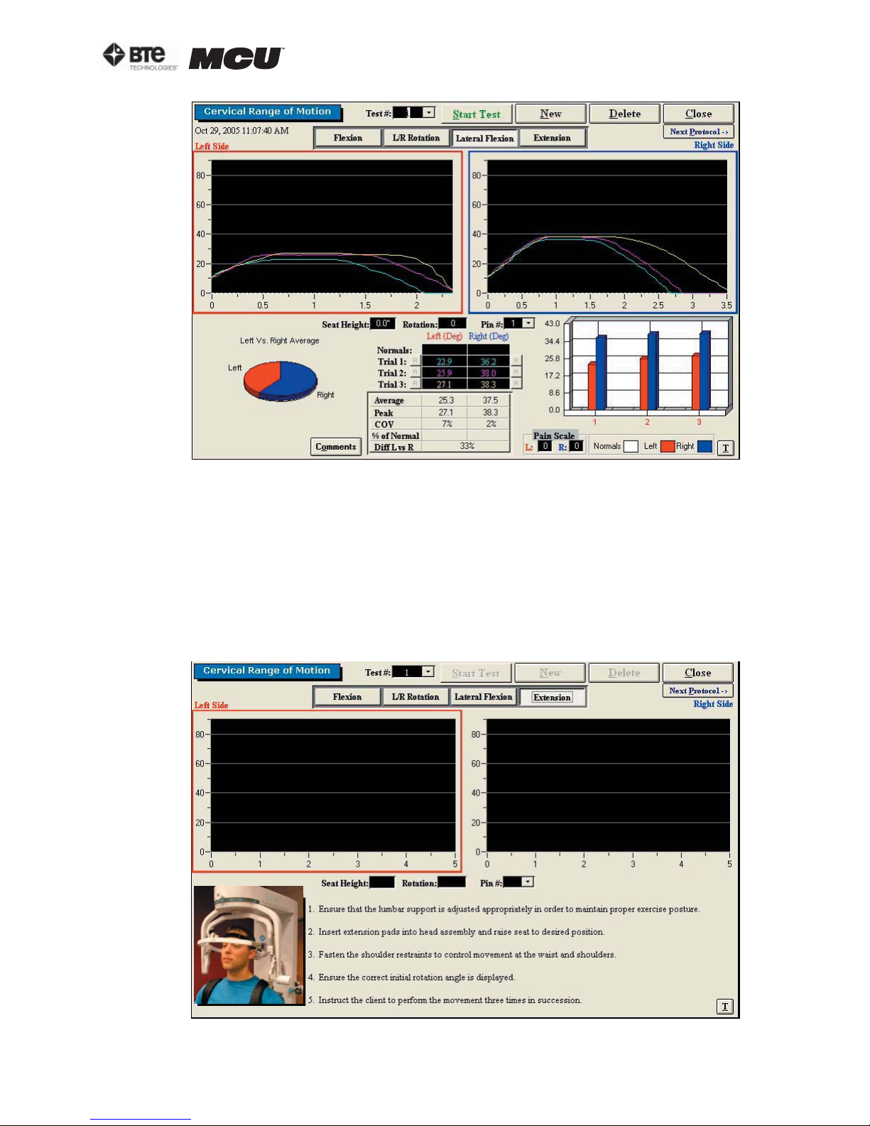
Figure 6-30. Cervical ROM - Completed Lateral Flexion Test
section 06
You may retest a trial by clicking on the R icon to the left or right of the trial table, depending on which trial you would like to redo. However, once a test has been closed, the
trials can not be retested.
5. UTILIZING THE ROM EXTENSION TEST
The ROM Extension protocol measures the patient’s range of motion with respect to the
extensor muscle group.
Step 1. Select the Extension icon. The Extension Testing screen will appear (Figure 6-
31). Note that the screen shown in the figure may differ from that on the computer.
Figure 6-31. Cervical ROM - Extension Test
40040005 rev. 000
page
17
Page 78
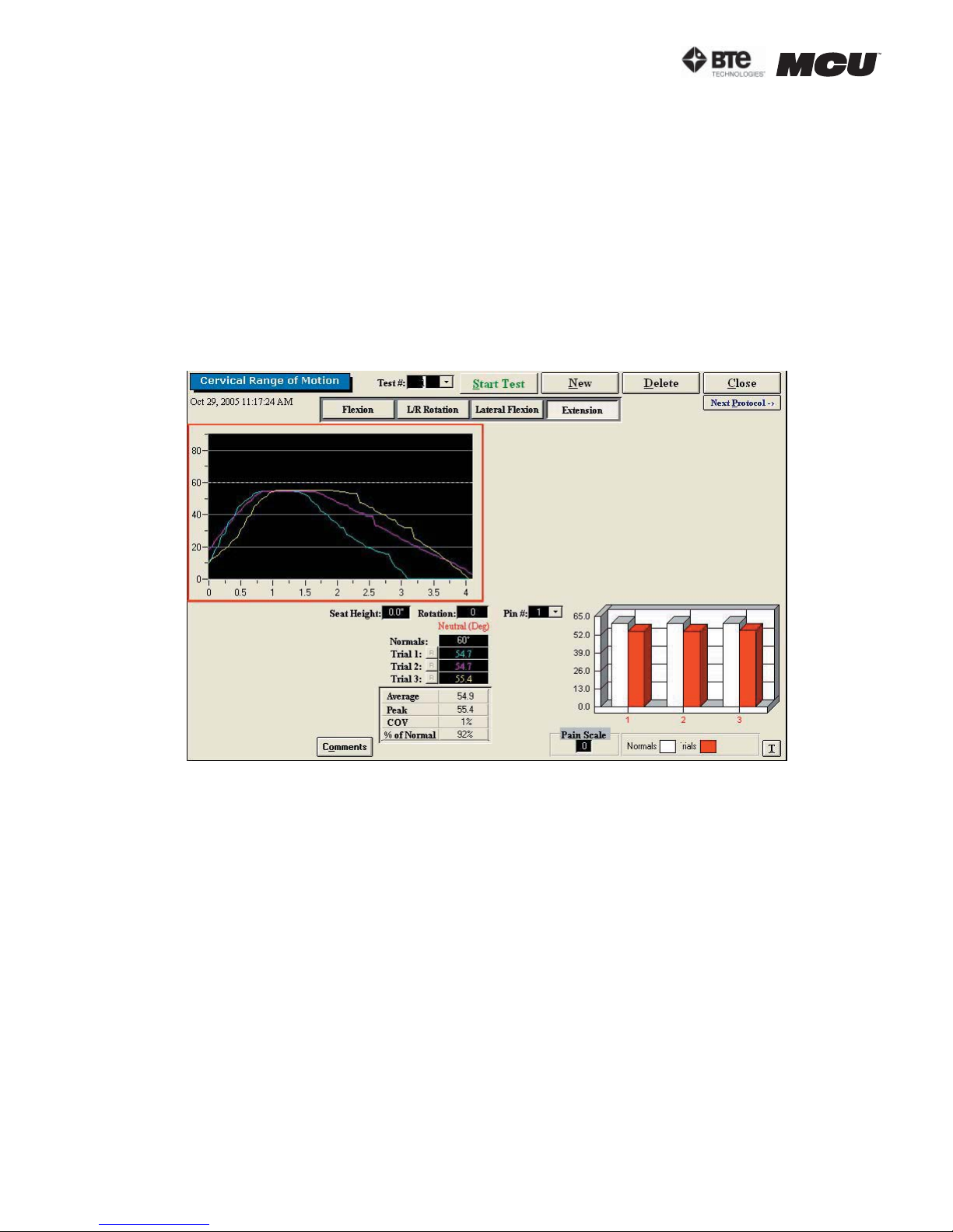
section 06
Step 2. Position the patient as described in Section 06-III of this manual.
Step 3. Click Start Test to begin testing.
Step 4. Once the test is completed, a pain scale will appear. Ask the patient to rate
his/her pain on a ten-point scale (0 is equivalent to no pain and 10 is equivalent to the
worst pain possible). Click on the number the patient determined and then click OK.
The ROM Extension test calls for three trials to be performed.
As the protocol is performed, the screen will display the results and averages via a line
graph, table, pie chart, and bar graph.
In addition to the test results, the screen will tabulate: the average ROM, peak ROM,
coefficient of variation (COV), and the percent of normal. The pain rating determined by
the patient will also appear in the pain scale text field (Figure 6-32).
Figure 6-32. Cervical ROM - Completed Extension Test
You may retest a trial by clicking on the R icon to the left or right of the trial table, depending on which trial you would like to redo. However, once a test has been closed, the
trials can not be retested.
IV. STRENGTH PROTOCOLS
A. POSITIONING THE PATIENT FOR NEUTRAL CERVICAL ISOMETRIC STRENGTH PROTOCOLS
In order to prepare for cervical strength testing, it is extremely important to understand
how to properly position the patient; this will prevent any injury during testing.
The following 7 steps are required prior to each type of strength testing. Outlined after
these 7 initial steps are the subsequent steps, which vary according to the test being performed.
Step 1. Insert the range-of-motion stop pin in the zero degree position on the halo (Figure
6-33).
page
18
40040005 rev. 000
Page 79
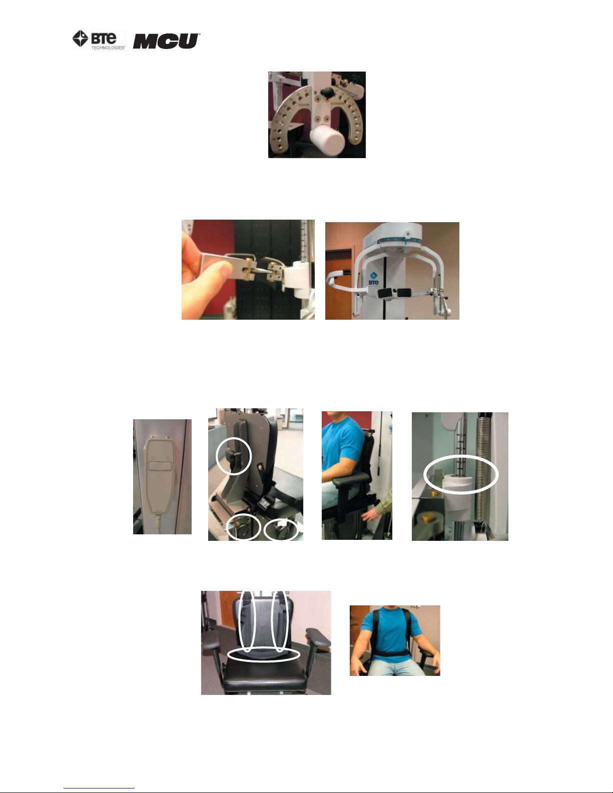
Figure 6-33 Insert
ROM Stop
Step 2. Lower the chair all the way down to its lowest position.
Step 3. Using the latch on the right side, open the halo (Figure 6-34).
Figure 6-34. Open Halo
section 06
Step 4. Ask the patient to sit in the chair.
Step 5. Adjust the height of the seat, the position of the seat, the position of the back
of the chair, the height of the back of the chair, and the arm rests to accommodate the
patient’s size, height, and posture. Set the halo height to 3 as a starting position (Figure
6-35).
Figure 6-35. Seat Adjustments
Step 6. Secure the patient with the waist strap and shoulder straps (Figure 6-36).
Figure 6-36. Waist and Shoulder Straps
Step 7. Close and lock the halo (Figure 6-37).
40040005 rev. 000
page
19
Page 80
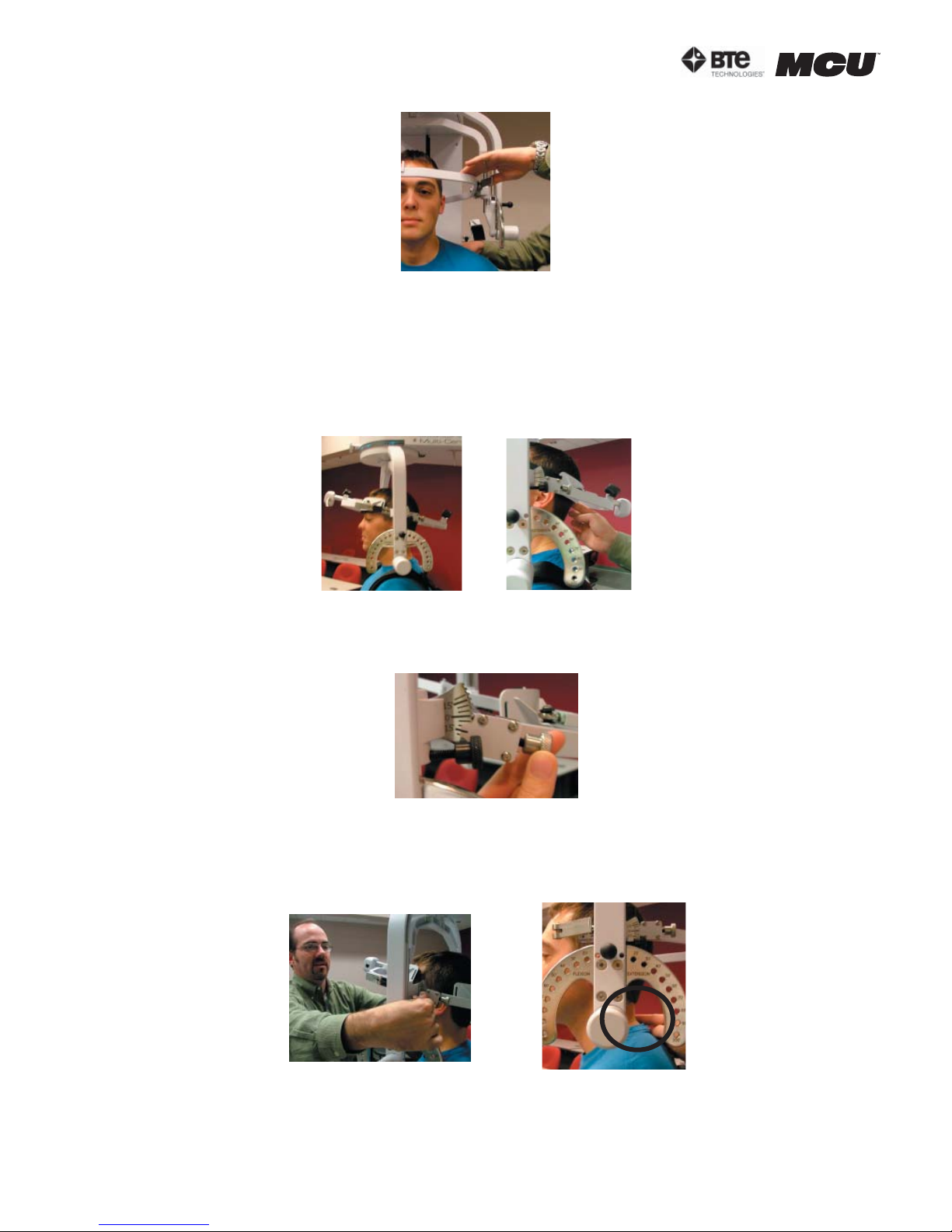
section 06
1. POSITIONING THE PATIENT FOR AN ISOMETRIC FLEXION/EXTENSION TEST
Step 8. For a flexion test, insert the front head brace. For an extension test, insert the
back head brace. Note that the bottom of the back brace is located at the external occipital protuberance (Figure 6-38).
Figure 6-37. Close
and Lock the Halo
Flexion Set-up
Location of
Back Brace
Figure 6-38. Initial Isometric Flexion
& Extension Set-up
Step 9. Set the halo to 15 degrees below the horizontal (Figure 6-39).
Figure 6-39. Halo Angle
Step 10. Position the head brace against the patient’s head.
Step 11. Make fine adjustments to the seat and halo such that C5/C6 of the patient’s
spine lines up with the pivot point of the halo (Figure 6-40).
Figure 6-40. Final Adjustments and Locating C5/C6
Step 12. Attach the RJ45 cable to the head brace being used and the RJ45 jack that is
page
20
40040005 rev. 000
Page 81
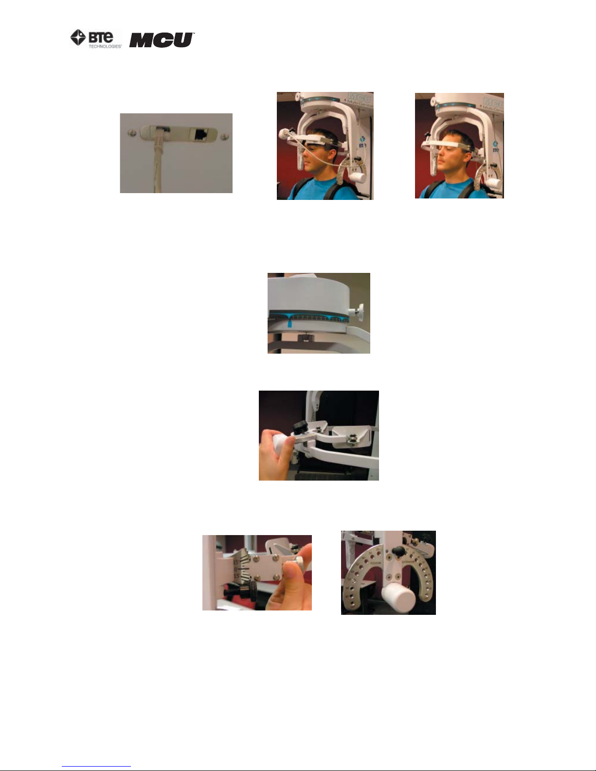
section 06
closest to the front of the unit at the top of the MCU™ (Figure 6-41).
Flexion
Figure 6-41. MCU™ RJ45 Jack and Final Isometric Flexion & Extension Set-ups
Extension
2. POSITIONING THE PATIENT FOR A ISOMETRIC LATERAL TEST
Step 8. Unlock the rotation pin and rotate the halo to 90 degrees right rotation. Lock
the rotation pin (Figure 6-42).
Figure 6-42. Halo at 90o Rotation
Step 9. Attach the head brace to the halo on the side being tested (Figure 6-43).
Figure 6-43. Attach Head Brace
Step 10.
Set the halo to 0 degrees with respect to the horizontal. Make sure the flexion/
extension angle is set to 0 degrees as well (Figure 6-44).
Figure 6-44. Set halo angles
Step 11. Position the head brace against the patient’s head.
Step 12. Make fine adjustments to the seat to line up C5/C6 of the patient’s spine with
the pivot point of the halo (Figure 6-45).
40040005 rev. 000
page
21
Page 82
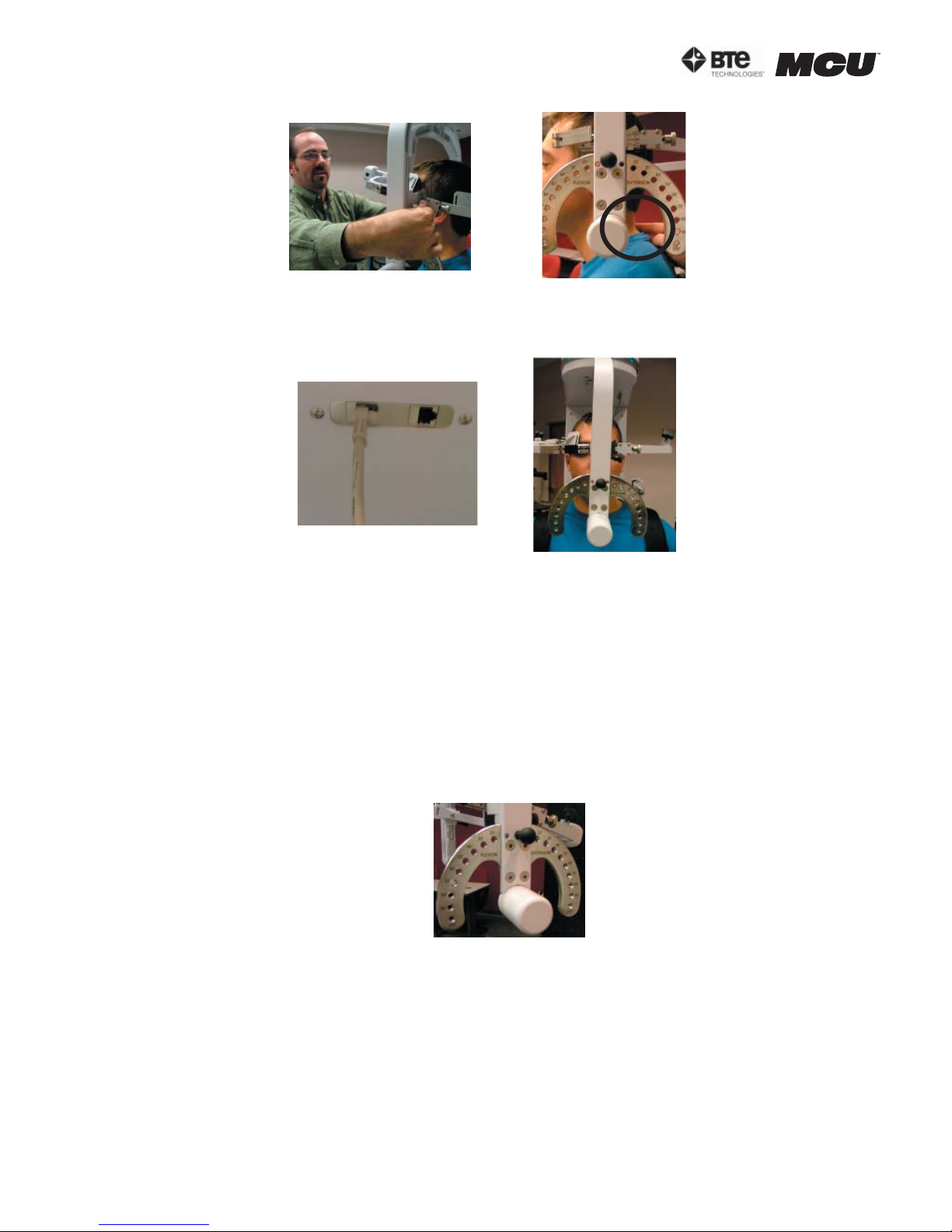
section 06
Step 13. Attach the RJ45 cable to the head brace being used and the RJ45 jack that is
closest to the front of the unit at the top of the MCU™ (Figure 6-46).
Figure 6-45. Final Adjustments and Locating C5/C6
Figure 6-46. MCU™ RJ45 Jack and Final Isometric Lateral Set-up
B. POSITIONING THE PATIENT FOR 25 DEGREE CERVICAL ISOMETRIC STRENGTH
PROTOCOLS
In order to prepare for cervical strength testing, it is extremely important to understand
how to properly position the patient; this will prevent any injury during testing.
The following 7 steps are required prior to each type of strength testing. Outlined after
these 7 initial steps are the subsequent steps, which vary according to the test being performed.
Step 1. Insert the range-of-motion stop pin in the zero degree position on the halo (Figure
6-47).
Figure 6-47. Insert
ROM Stop
Step 2. Lower the chair all the way down to its lowest position.
Step 3. Using the latch on the right side, open the halo (Figure 6-48).
page
22
40040005 rev. 000
Page 83
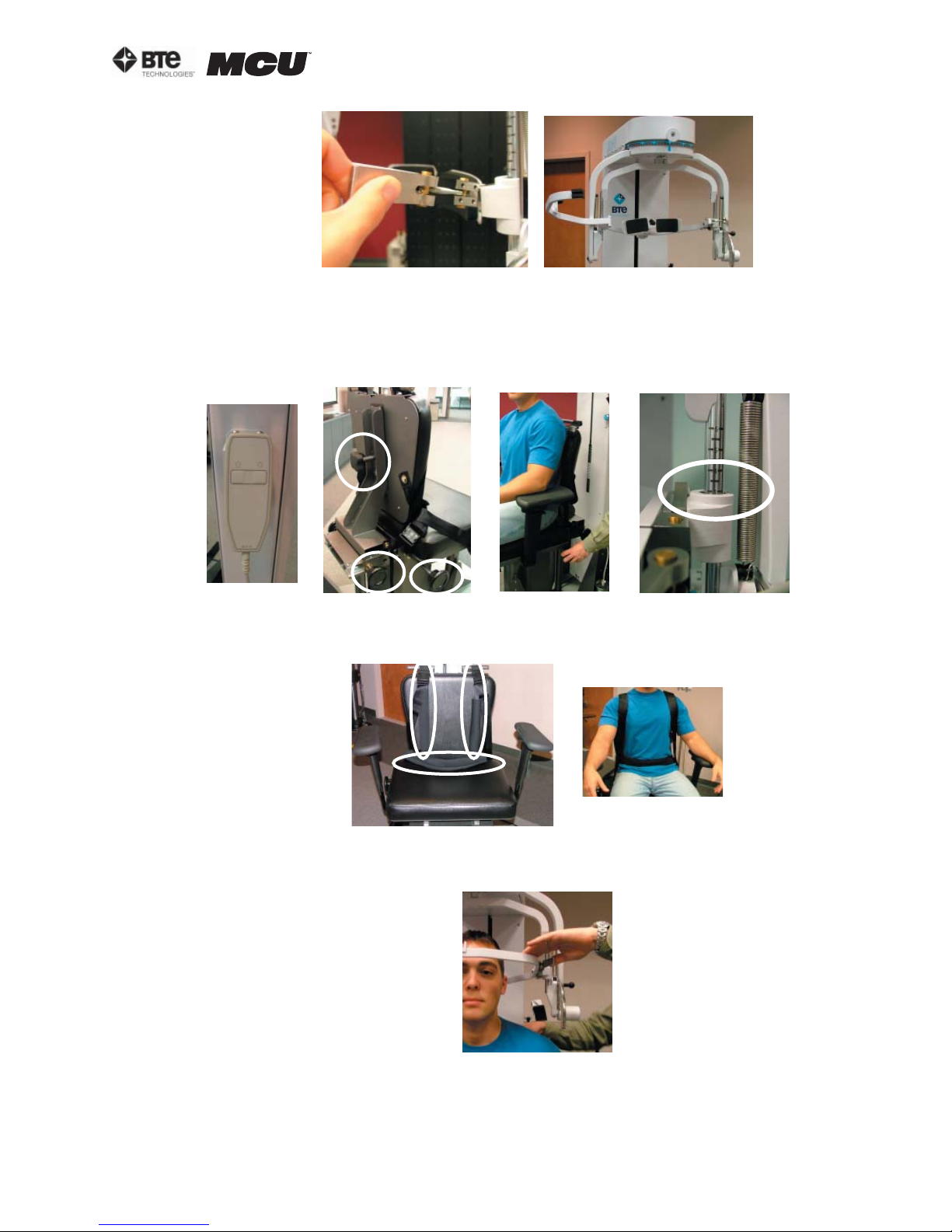
section 06
Figure 6-48. Open Halo
Step 4. Ask the patient to sit in the chair.
Step 5. Adjust the height of the seat, the position of the seat, the position of the back
of the chair, the height of the back of the chair, and the arm rests to accommodate the
patient’s size, height, and posture (Figure 6-49).
Figure 6-49. Seat Adjustments
Step 6. Secure the patient with the waist strap and shoulder straps (Figure 6-50).
Figure 6-50. Waist and Shoulder Straps
Step 7. Close and lock the halo (Figure 6-51).
40040005 rev. 000
Figure 6-51. Close
and Lock the Halo
page
23
Page 84
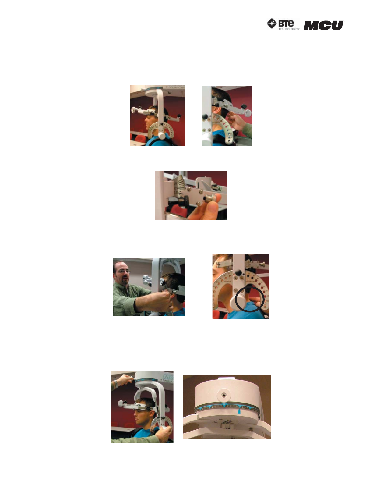
section 06
1. POSITIONING THE PATIENT FOR A 25 DEGREE ISOMETRIC FLEXION/EXTENSION TEST
Step 8. For a flexion test, insert the front head brace. For an extension test, insert the
back head brace. Note that the bottom of the back brace is located at the external occipital protuberance (Figure 6-52).
Step 9. Set the halo to 15 degrees below the horizontal (Figure 6-53).
Location of
Flexion Set-up
Figure 6-52. Initial Isometric Flexion
& Extension Set-up
Back Brace
Figure 6-53. Halo Angle
Step 10. Position the head brace against the patient’s head.
Step 11. Make fine adjustments to the seat to line up C5/C6 of the patient’s spine with
the pivot point of the halo (Figure 6-54).
Figure 6-54. Final Adjustments and Locating C5
Step 12. While holding onto the side of the halo, unlock the rotation pin, which is located at the top middle of the halo. If you’re testing the patient’s left side, rotate the
halo 25 degrees right and then lock the rotation pin. Rotate the halo 25 degrees to the
left to test the patient’s right side (Figure 6-55).
Unlock Rotation Pin
25o Right
Figure 6-55. Halo Rotation of 25
page
24
o
40040005 rev. 000
Page 85
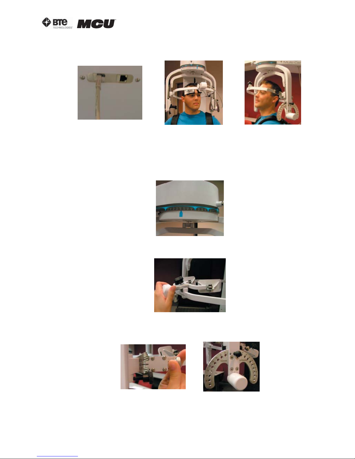
section 06
Step 13. Attach the RJ45 cable to the head brace being used and the RJ45 jack that is
closest to the front of the unit at the top of the MCU™ (Figure 6-56).
Flexion Extension
Figure 6-56. MCU™ RJ45 Jack and Final 25o Isometric Flexion & Extension Set-ups
2. POSITIONING THE PATIENT FOR A 25 DEGREE ISOMETRIC LATERAL TEST
Step 8. Unlock the rotation pin, which is located at the top middle of the halo. If
you’re testing the patient’s left side, rotate the halo 65 degrees toward the right, and
then lock the rotation pin. Rotate the halo 65 degrees toward the left when testing the
patient’s right side (Figure 6-57). Note that the figures show a set-up for testing the
patient’s right side.
o
Figure 6-57. Halo Rotation of 25
Lateral
Step 9. Attach the head brace to the halo on the side being tested (Figure 6-58).
Figure 6-58. Attach Head Brace
Step 10. Set the halo to 0 degrees with respect to the horizontal. Make sure the flexion/
extension angle is set to 0 degrees as well (Figure 6-59).
Figure 6-59. Set halo angles
Step 11. Position the head brace against the patient’s head.
Step 12. Make fine adjustments to the seat to line up C5/C6 of the patient’s spine with
40040005 rev. 000
page
25
Page 86
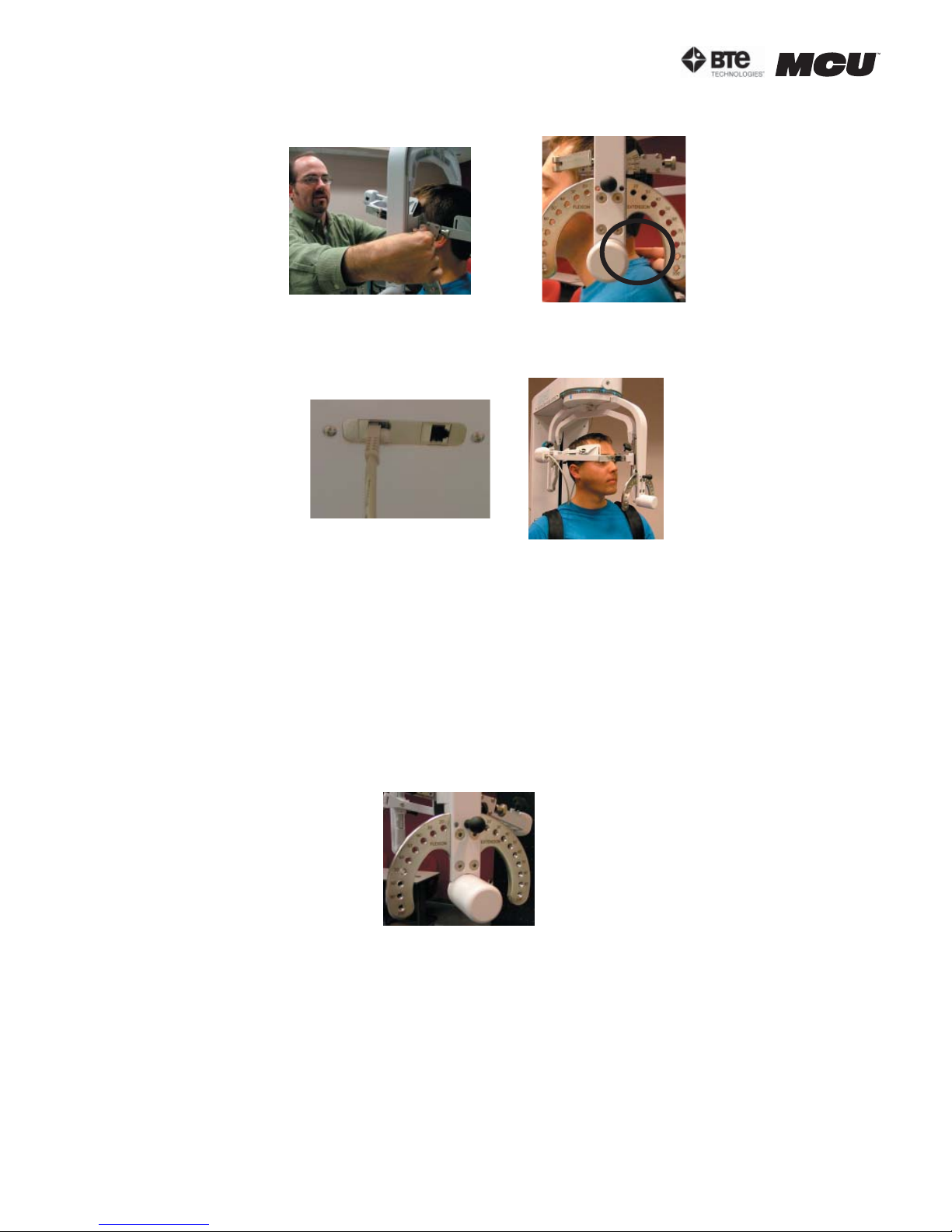
section 06
the pivot point of the halo (Figure 6-60).
Step 13. Attach the RJ45 cable to the head brace being used and the RJ45 jack that is
closest to the front of the unit at the top of the MCU™ (Figure 6-61).
Figure 6-60. Final Adjustments and Locating C5
Figure 6-61. MCU™ RJ45 Jack and Final
25o Isometric Lateral Set-up
C. POSITIONING THE PATIENT FOR 45 DEGREE CERVICAL ISOMETRIC STRENGTH
PROTOCOLS
In order to prepare for cervical strength testing, it is extremely important to understand
how to properly position the patient; this will prevent any injury during testing.
The following 7 steps are required prior to each type of strength testing. Outlined after
these 7 initial steps are the subsequent steps, which vary according to the test being performed.
Step 1. Insert the range-of-motion stop pin in the zero degree position on the halo (Figure
6-62).
Figure 6-62. Insert
ROM Stop
Step 2. Lower the chair all the way down to its lowest position.
Step 3. Using the latch on the right side, open the halo (Figure 6-63).
page
26
40040005 rev. 000
Page 87
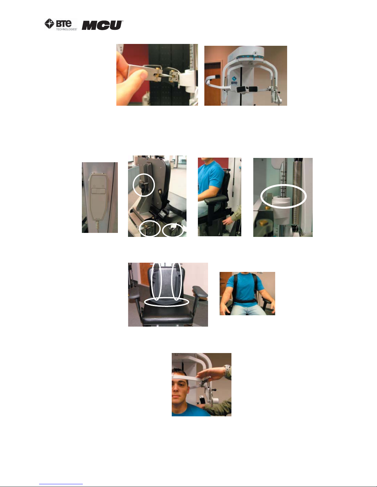
section 06
Figure 6-63. Open Halo
Step 4. Ask the patient to sit in the chair.
Step 5. Adjust the height of the seat, the position of the seat, the position of the back
of the chair, the height of the back of the chair, and the arm rests to accommodate the
patient’s size, height, and posture. Set the halo height to 3 as a starting position (Figure
6-64).
Figure 6-64. Seat Adjustments
Step 6. Secure the patient with the waist strap and shoulder straps (Figure 6-65).
Figure 6-65. Waist and Shoulder Straps
Step 7. Close and lock the halo (Figure 6-66).
Figure 6-66. Close
and Lock the Halo
40040005 rev. 000
page
27
Page 88
section 06
1. POSITIONING THE PATIENT FOR A 45 DEGREE ISOMETRIC FLEXION/EXTENSION TEST
Step 8. For a flexion test, insert the front head brace. For an extension test, insert the
back head brace. Note that the bottom of the back brace is located at the external occipital protuberance (Figure 6-67).
Step 9. Set the halo to 15 degrees below the horizontal (Figure 6-68).
Location of
Flexion Set-up
Figure 6-67. Initial Isometric Flexion
& Extension Set-up
Back Brace
Figure 6-68. Halo Angle
Step 10. Position the head brace against the patient’s head.
Step 11. Make fine adjustments to the seat to line up C5/C6 of the patient’s spine with
the pivot point of the halo (Figure 6-69).
Figure 6-69. Final Adjustments and Locating C5/C6
Step 12. While holding onto the side of the halo, unlock the rotation pin, which is located at the top middle of the halo. If you’re testing the patient’s left side, rotate the
halo to 45 degrees right rotation and then lock the rotation pin. Rotate the halo to 45
degrees left rotation to test the patient’s right side (Figure 6-70).
Unlock Rotation Pin
45o Right
Figure 6-70. Halo Rotation of 45
page
28
o
40040005 rev. 000
Page 89
section 06
Step 13. Attach the RJ45 cable to the head brace being used and the RJ45 jack that is
closest to the front of the unit at the top of the MCU™ (Figure 6-71).
Flexion Extension
Figure 6-71. MCU RJ45 Jack and Final 25o Isometric Flexion & Extension Set-ups
2. POSITIONING THE PATIENT FOR A 45 DEGREE ISOMETRIC LATERAL TEST
Step 8. Unlock the rotation pin, which is located at the top middle of the halo. If
you’re testing the patient’s left side, rotate the halo to 45 degrees right rotation, and
then lock the rotation pin. Rotate the halo to 45 degrees left rotation when testing the
patient’s right side (Figure 6-72). Note that the figures show a set-up for testing the
patient’s right side.
Figure 6-72. Halo Rotation of 45
o
Lateral
Step 9. Attach the head brace to the halo on the side being tested (Figure 6-73).
Figure 6-73. Attach Head Brace
Step 10. Set the halo to 0 degrees with respect to the horizontal. Make sure the flexion/
extension angle is set to 0 degrees as well (Figure 6-74).
Figure 6-74. Set halo angles
Step 11. Position the head brace against the patient’s head.
Step 12. Make fine adjustments to the seat to line up C5/C6 of the patient’s spine with
the pivot point of the halo (Figure 6-75).
40040005 rev. 000
page
29
Page 90
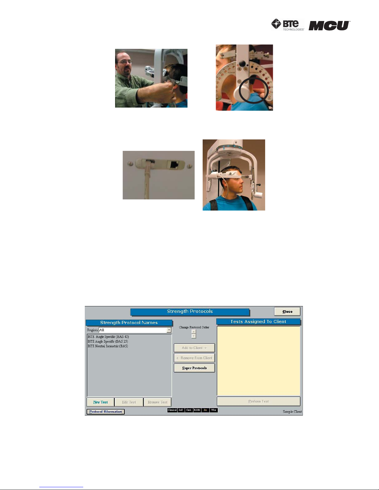
section 06
Step 13. Attach the RJ45 cable to the head brace being used and the RJ45 jack that is
closest to the front of the unit at the top of the MCU™ (Figure 6-76).
Figure 6-75. Final Adjustments and Locating C5/C6
Figure 6-76. MCU™ RJ45 Jack and Final
45o Isometric Lateral Set-up
D. UTILIZING THE CERVICAL STRENGTH PROTOCOLS
1. ACCESSING THE CERVICAL STRENGTH PROTOCOLS
Access the pre-programmed Strength protocols by clicking the Strength Tests icon on
the Home Screen.
This will bring you to the Strength Protocols main page. From this page you have the
ability to access all the pre-programmed protocols, including those in hibernation, add
and remove tests to clients, create new isometric strength tests, edit tests, and delete
tests (Figure 6-77).
Figure 6-77. Strength Protocols
Note that three strength protocols have been designed for the Multi-Cervical™ Unit:
MCU™ Neutral Isometric, MCU™ Angle Specific 25 Degrees, and MCU™ Angle Specific 45
Degrees. The only difference between the three protocols is the rotation angle at which
page
30
40040005 rev. 000
Page 91
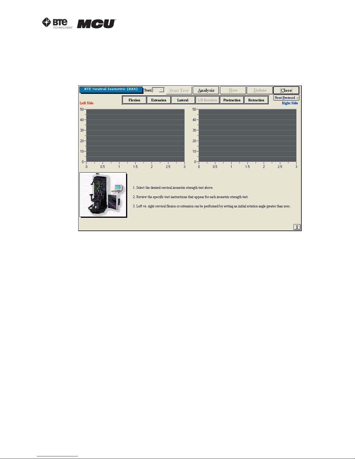
section 06
the halo is set (i.e. 0 degrees, 25 degrees, and 45 degrees).
Step 1. Assign a test to a client by highlighting the test in the left box and clicking Add
to Client or by double clicking on the test in the left box.
Step 2. Once a test has been assigned to a client, highlight the test name in the right
box and click Perform Test to bring up the testing screen (Figure 6-78).
Figure 6-78. Cervical Strength Main Screen
The initial Cervical Strength protocol screens contain the following features:
• Name of the test
• Start Test icon, which changes to Stop Test after the test has begun
• Analysis icon to extensively analyze the data of a completed test
• New icon to begin a new set of test results
• Delete icon to delete the selected test’s results
• Close icon to return to the protocol screen
• Next Protocol icon to move on to the next protocol
• Flexion icon, which switches to the Flexion test screen
• Extension icon, which switches to the Extension test screen
• Lateral icon, which switches to the Lateral test screen
• Protraction icon, which switches to the Protraction screen
• Retraction icon, which switches to the Retraction screen
• Graphs and tables to illustrate the test results
• Instructions on how to perform the tests
• Threshold icon, which allows a threshold force to be set
2. UTILIZING THE STRENGTH FLEXION TEST
The Strength Flexion test measures the patient’s strength with respect to the flexor
muscle group.
Step 1. Select the Flexion icon. The Flexion Testing screen will appear (Figure 6-79).
Note that the screen shown in the figure may differ from that on the computer.
40040005 rev. 000
page
31
Page 92
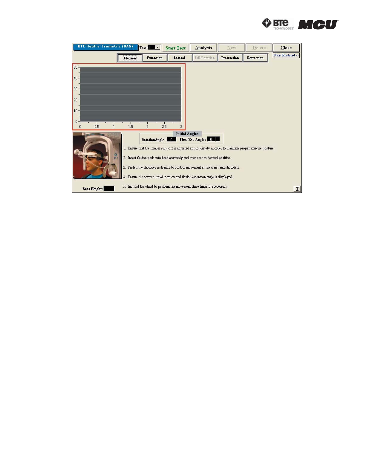
section 06
Figure 6-79. Cervical Strength - Flexion Test
Step 2. Position the patient as described in Section 06-IV of this manual.
Step 3. Click Start Test to begin testing.
Step 4. Once the test is completed, a pain scale will appear. Ask the patient to rate
his/her pain on a ten-point scale (0 is equivalent to no pain and 10 is equivalent to the
worst pain possible). Click on the number the patient stated and then click OK.
The Strength Flexion test calls for three trials to be performed.
As the protocol is performed, the screen will display the results and averages via a line
graph, table, pie chart, and bar graph.
In addition to the test results, the screen will tabulate: the average force, peak force,
coefficient of variation (COV), and the percent of normal. The pain ratings determined
by the patient will also appear in the pain scale text field (Figure 6-80).
page
32
40040005 rev. 000
Page 93
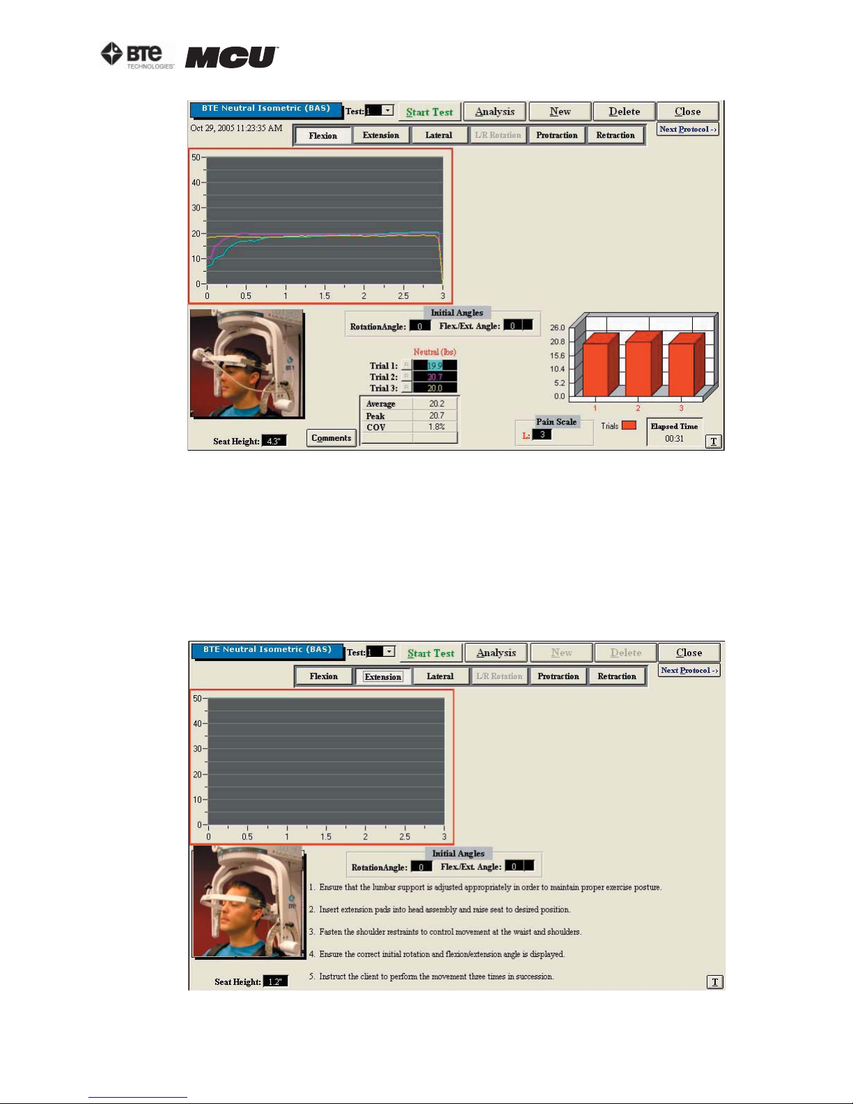
Figure 6-80. Cervical Strength - Completed Flexion Test
section 06
You may retest a trial by clicking on the R icon to the left or right of the trial table, depending on which trial you would like to redo. However, once a test has been closed, the
trials can not be retested.
3. UTILIZING THE STRENGTH EXTENSION TEST
The Strength Extension test measures the patient’s strength with respect to the extensor muscle group.
Step 1. Select the Extension icon. The Extension Testing screen will appear (Figure 6-
81). Note that the screen shown in the figure may differ from that on the computer.
Figure 6-81. Cervical Strength - Extension Test
40040005 rev. 000
page
33
Page 94
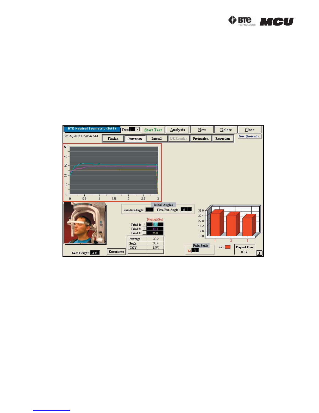
section 06
Step 2. Position the patient as described in Section 06-IV of this manual.
Step 3. Click Start Test to begin testing.
Step 4. Once the test is completed, a pain scale will appear. Ask the patient to rate
his/her pain on a ten-point scale (0 is equivalent to no pain and 10 is equivalent to the
worst pain possible). Click on the number the patient stated and then click OK.
The Strength Extension test calls for three trials to be performed.
As the protocol is performed, the screen will display the results and averages via a line
graph, table, pie chart, and bar graph.
In addition to the test results, the screen will tabulate: the average force, peak force,
coefficient of variation (COV), and the percent of normal. The pain ratings determined
by the patient will also appear in the pain scale text field (Figure 6-82).
Figure 6-82. Cervical Strength - Completed Extension Test
You may retest a trial by clicking on the R icon to the left or right of the trial table, depending on which trial you would like to redo. However, once a test has been closed, the
trials can not be retested.
4. UTILIZING THE STRENGTH LATERAL TEST
The Strength Lateral test measures the patient’s strength with respect to the lateral
muscle group.
Step 1. Select the Lateral icon. The Lateral Testing screen will appear (Figure 6-83).
Note that the screen shown in the figure may differ from that on the computer.
page
34
40040005 rev. 000
Page 95
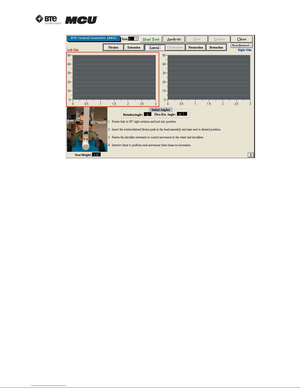
Figure 6-83. Cervical Strength - Lateral Test
section 06
Step 2. Position the patient as described in Section 06-IV of this manual.
Step 3. Click Start Test to begin testing.
Step 4. Once each side is completed, a pain scale will appear. Ask the patient to rate
his/her pain on a ten-point scale (0 is equivalent to no pain and 10 is equivalent to the
worst pain possible). Click on the number the patient determined and then click OK.
The Strength Lateral test calls for three trials to be performed per side.
As the protocol is performed, the screen will display the results and averages via a line
graph, table, pie chart, and bar graph.
In addition to the test results, the screen will tabulate: the average force, peak force,
coefficient of variation (COV), and the percent of normal. The pain ratings determined
by the patient will also appear in the pain scale text field (Figure 6-84).
40040005 rev. 000
page
35
Page 96
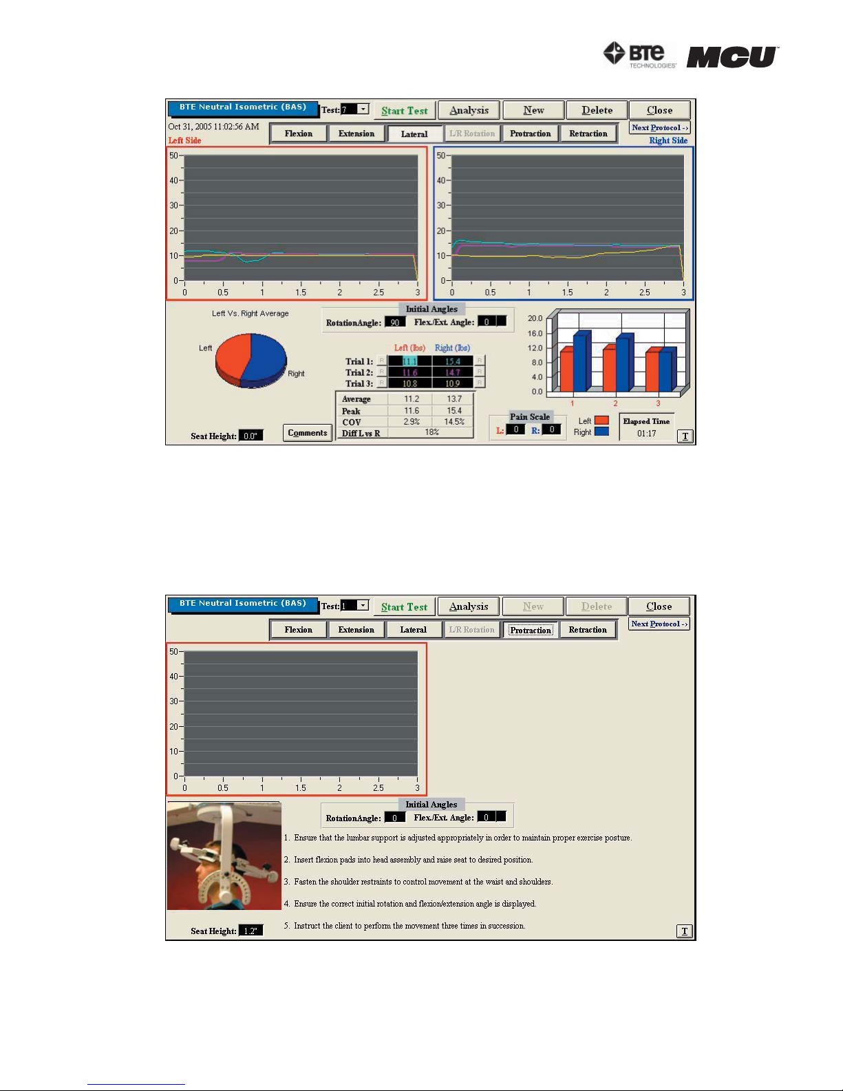
section 06
Figure 6-84. Cervical Strength - Completed Lateral Test
You may retest a trial by clicking on the R icon to the left or right of the trial table, depending on which trial you would like to redo. However, once a test has been closed, the
trials can not be retested.
5. UTILIZING THE STRENGTH PROTRACTION TEST
Step 1. Select the Protraction icon. The Protraction Testing screen will appear (Figure
6-85). Note that the screen shown in the figure may differ from that on the computer.
Figure 6-85. Cervical Strength - Protraction Test
Step 2. Position the patient as described in Section 06-IV of this manual.
page
36
40040005 rev. 000
Page 97
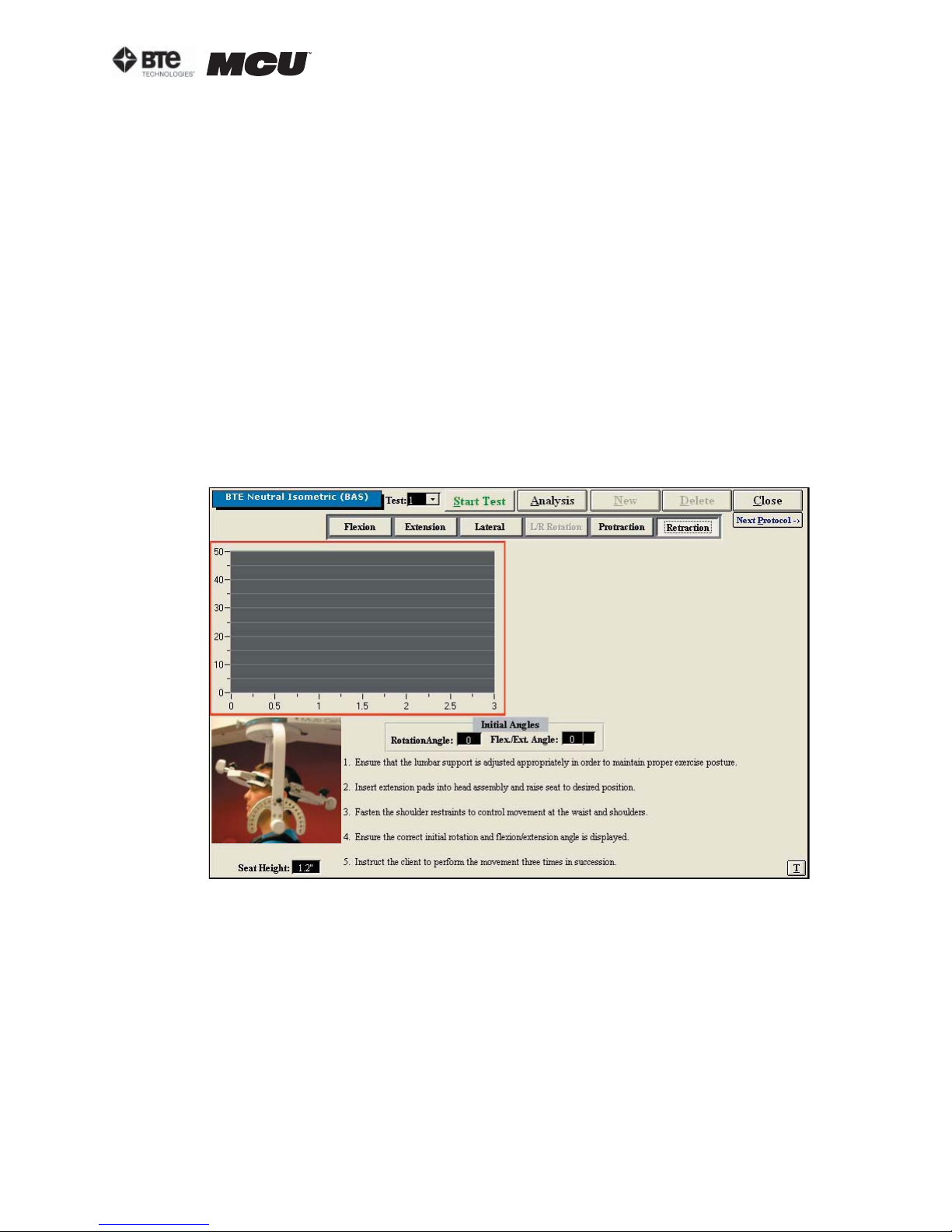
section 06
Step 3. Click Start Test to begin testing.
Step 4. Once the test is completed, a pain scale will appear. Ask the patient to rate
his/her pain on a ten-point scale (0 is equivalent to no pain and 10 is equivalent to the
worst pain possible). Click on the number the patient stated and then click OK.
The Strength Protraction test calls for three trials to be performed.
As the protocol is performed, the screen will display the results and averages via a line
graph, table, pie chart, and bar graph.
In addition to the test results, the screen will tabulate: the average force, peak force,
coefficient of variation (COV), and the percent of normal. The pain ratings determined
by the patient will also appear in the pain scale text field.
You may retest a trial by clicking on the R icon to the left or right of the trial table, depending on which trial you would like to redo. However, once a test has been closed, the
trials can not be retested.
6. UTILIZING THE STRENGTH RETRACTION TEST
Step 1. Select the Retraction icon. The Retraction Testing screen will appear (Figure
6-86). Note that the screen shown in the figure may differ from that on the computer.
Figure 6-86. Cervical Strength - Retraction Test
Step 2. Position the patient as described in Section 06-IV of this manual.
Step 3. Click Start Test to begin testing.
Step 4. Once the test is completed, a pain scale will appear. Ask the patient to rate
his/her pain on a ten-point scale (0 is equivalent to no pain and 10 is equivalent to the
worst pain possible). Click on the number the patient stated and then click OK.
The Retraction Strength test calls for three trials to be performed.
As the protocol is performed, the screen will display the results and averages via a line
graph, table, pie chart, and bar graph.
In addition to the test results, the screen will tabulate: the average force, peak force,
40040005 rev. 000
page
37
Page 98
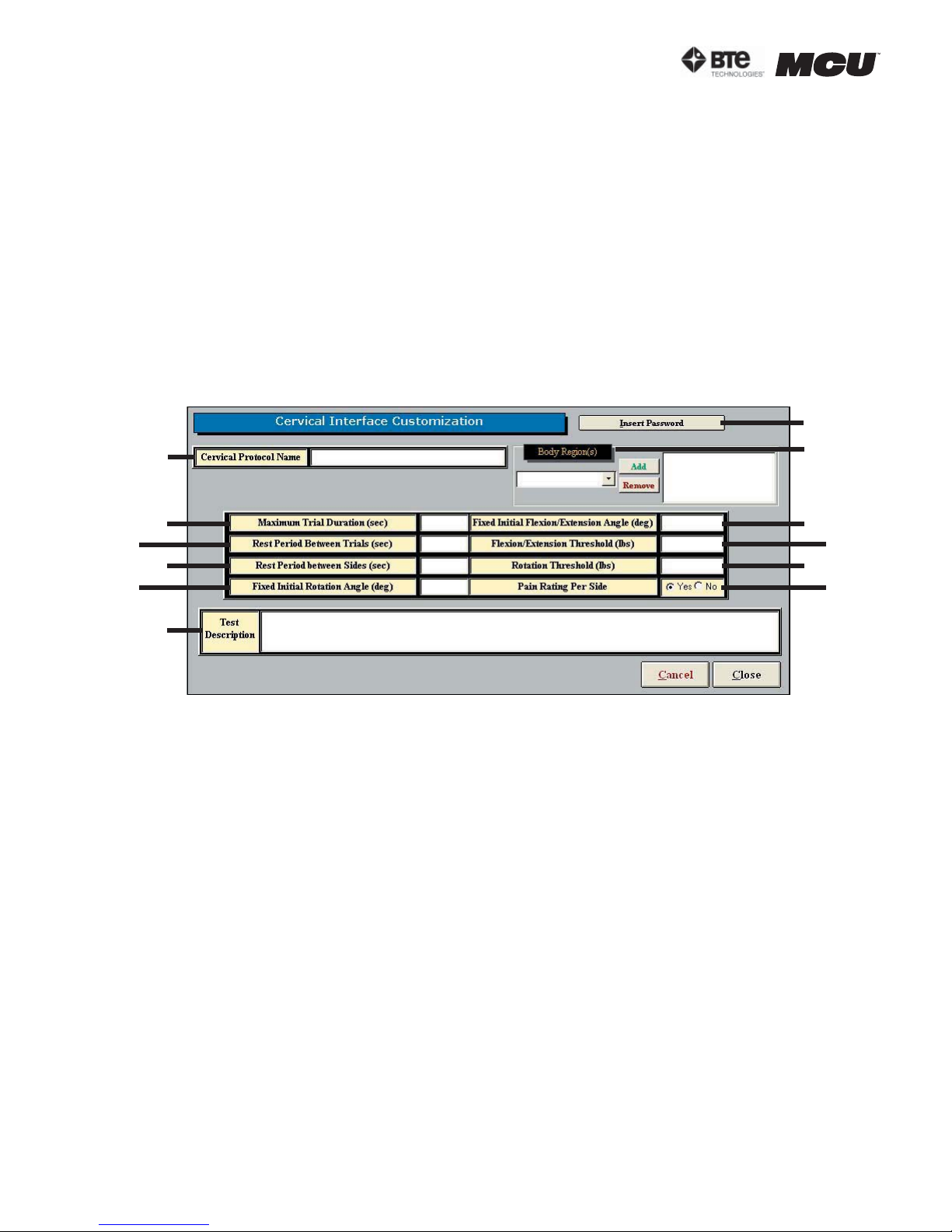
section 06
coefficient of variation (COV), and the percent of normal. The pain ratings determined
by the patient will also appear in the pain scale text field.
You may retest a trial by clicking on the R icon to the left or right of the trial table, depending on which trial you would like to redo. However, once a test has been closed, the
trials can not be retested.
7. CREATING CUSTOM CERVICAL INTEGRATION PROTOCOLS
Access the pre-programmed Strength protocols by clicking the Strength Tests icon on
the Home Screen.
This will bring you to the Strength Protocols main page, where you can edit and create
tests.
Create a new test by clicking on New Test and then clicking Cervical Integration (Fig-
ure 6-87).
G
A
B
C
D
E
F
Figure 6-87. Custom Cervical Integration Protocol
The following can be created on Custom Cervical Integration Protocols:
A. Cervical Protocol Name - Type in the name of the test
B. Maximum Trial Duration - Set the maximum amount of time (seconds) for the trial
duration
C. Rest Period Between Trials - Set the amount of time (seconds) to rest between trials
D. Rest Period Between Sides - Set the amount of time (seconds) to rest between
switching sides
H
I
J
K
L
E. Fixed Initial Rotation Angle (deg) - Set the initial angle (degrees) for a rotation test
F. Test Description - Type in any description that should be included on the test
G. Insert Password - Choose whether a password is required to edit the test – if this op-
tion is selected, any user will be prompted for the password whenever he or she tries to
edit the test.
H. Body Region - Select which body region is to be evaluated
I. Fixed Initial Flexion/Extension Angle (deg) - Set the initial (degrees) for a flexion or
extension test
J. Flexion/Extension Threshold (lbs) - Set the amount of force (lbs) required for a flex-
page
38
40040005 rev. 000
Page 99
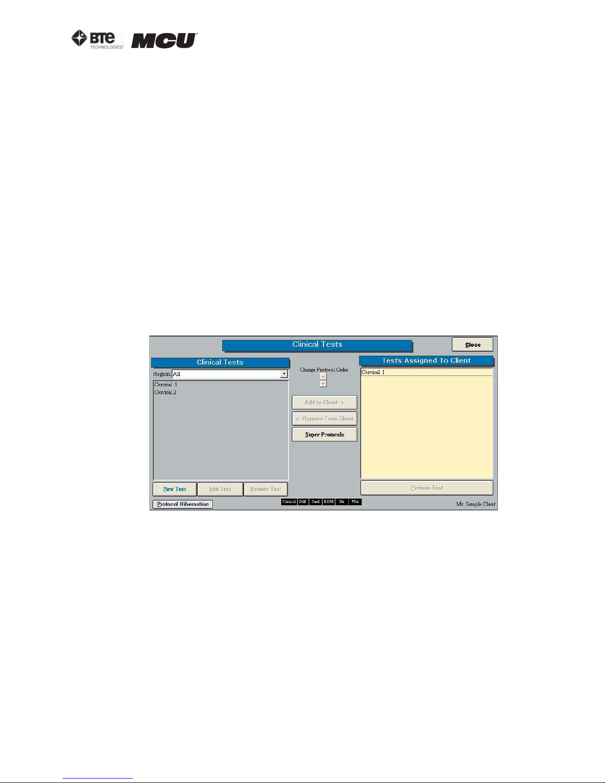
section 06
ion or extension test to begin
K. Rotation Threshold (lbs) - Set the amount of force (lbs) required for a rotation test to
begin
L. Pain Rating Per Side - Choose whether to display the pain rating scale
Once the screen has been closed, the protocol is saved under the assigned test name
with the new specifications.
V. CLINICAL PROTOCOLS
ODES includes several pre-programmed Clinical protocols, which are intended to be completed
without the use of any tools. These protocols help to identify any injuries or anomalies the patient may have.
A. UTILIZING CLINICAL PROTOCOLS
Access the pre-programmed Clinical protocols by clicking the Clinical icon on the Home
Screen.
This will bring you to the Clinical Protocols main page. From this page you have the ability
to access all the pre-programmed protocols, including those in hibernation, add and remove tests to clients, create new range of motion tests, edit tests, and delete tests (Figure
6-88).
Figure 6-88. Clinical Protocols
Step 1. Assign a test to a client by highlighting the test in the left box and clicking Add to
Client or by double clicking on the test in the left box.
Step 2. Once a test has been assigned to a client, highlight the test name in the right box
and click Perform Test to bring up the testing screen (Figure 6-89).
40040005 rev. 000
page
39
 Loading...