

Page 1
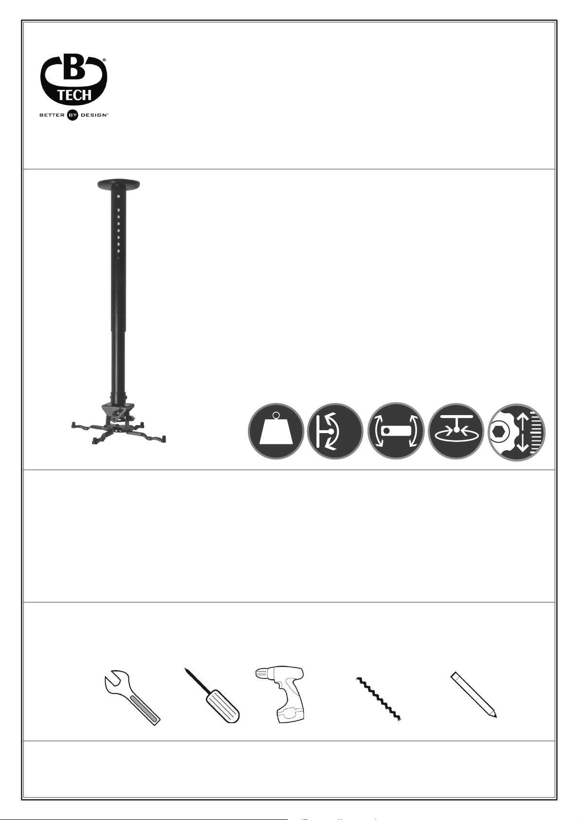
BT899-AD
ADJUSTABLE DROP PROJECTOR CEILING MOUNT
WITH MICRO-ADJUSTMENT
INSTALLATION GUIDE & PARTS LIST
This Pack Contains 1 Mount
PLEASE KEEP THIS FOR FUTURE REFERENCE
FEATURES
Ɣ Telescopic ceiling mount designed for projectors up to 25kg (55lbs)
Ɣ Adjustable drop: 743mm to 1143mm (in 25mm increments)
Ɣ +/-13° tilt adjustment, +/-6° roll adjustment and 360° swivel
Ɣ Maximum distance between any two fixing points
on projector: 370mm (14.6")
Ɣ Optional micro-adjustment for short throw projectors
Ɣ Unique ‘Carousel’ mounting plate for universal compatibility
Ɣ Suitable for projectors using M2.5, M3, M4, M5 and M6 fixings
Ɣ Integrated cable management for a smart installation
Ɣ All mounting hardware & fixings included
ß
ß
360°
25kg
ß
ß
CONTENTS
Installation Safety Notes.....................................................................................................................2
Parts List.............................................................................................................................................4
Installation Instructions.......................................................................................................................6
Product Dimensions..........................................................................................................................11
B-Tech Contact Details.....................................................................................................................12
INSTALLATION TOOLS REQUIRED
13mm
spanner or socket
Crosshead
screwdriver
Drill
10mm masonry bit
or 6mm wood bit
B-TECH AV MOUNTS
www.btechavmounts.com
Pencil
Page 2
Page 3

Page 4
BT899-AD
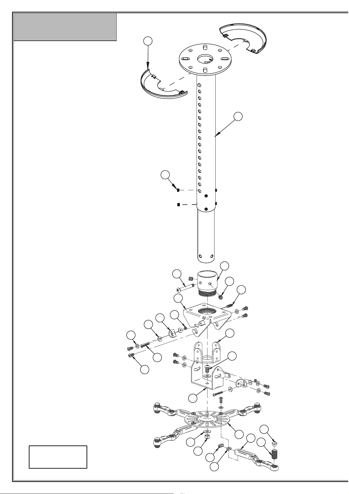
PARTS LIST
2
1
3
Suitable for loads
up to 25kg
16
15
24
23
22
27
25
26
28
18
4
5
13
6
7
17
14
11
12
10
8
9
4
Page 5
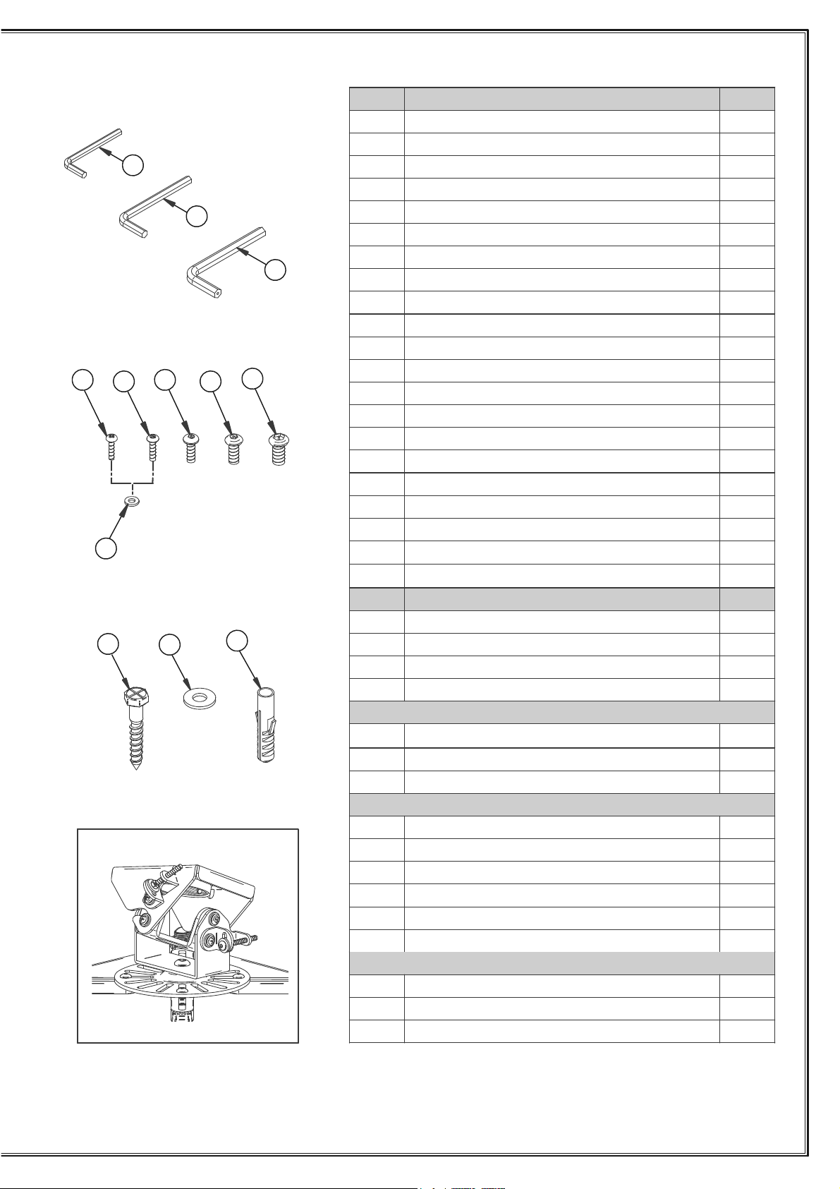
ITEM PART NAME QTY
1
2
1 1
2COVER PLATE (HALF) 2
8GRUB SCREW 3
1
1 ETALP GNINIOJ
1 ETALP LEVIWS
1 LESUORAC
4 MRA GNITNUOM
4 WERCS GNILEVEL
4 REVOC WERCS GNILEVEL
4 PAC MRA GNITNUOM
4 TUN ERAUQS 6M
1 WERCS YTIRUCES mm51x 8M
1TUN COLYN 8M
21 WERCS YTIRUCES mm21 x 6M
01 REHSAW LATEM 6M
2 REHSAW CITSALP 8M
1
TELESCOPIC CELING PLATE
19
MOUNTING PLATE
4
20
21
A
C
B
E
D
F
5
6
7
8
9
01
11
21
31
41
51
61
17
18 M6 x 20mm GRUB SCREW 1
HEX KEY
19
20
21
mm3
4mm HEX KEY
5mm HEX KEY
A1
A2
A3
Micro-adjustment assembled
22
23
42
52
26
POLE ADAPTOR
27
28
F
MICRO-ADJUSTMENT
ADAPTOR
INTERFACE KIT
FIXING KIT
2 TEKCARB TNEMTSUJDA ORCIM
2 WERCS YTIRUCES mm03 x 4M
4 REHSAW LATEM 4M
2TUN COLYN 4M
1
1 TLOB YTEFAS mm06 x 8M
2 WERCS BURG mm6 x 01M
4 WERCS mm21 x 5.2M A
4 WERCS mm21 x 3M B
4 WERCS YTIRUCESmm21 x 4M C
4 WERCS YTIRUCES mm21 x 5M D
4 WERCS YTIRUCES mm21 x 6M E
4 )A & B TRAP ROF( REHSAW LATEM 3M
4 WERCS HCAOC mm05 x 8M 1A
4 )1A TRAP ROF( REHSAW LATEM 8M 2A
4 )1A TRAP ROF( GULP LLAW 01 .oN 3A
PLEASE KEEP THIS FOR FUTURE REFERENCE
5
Page 6
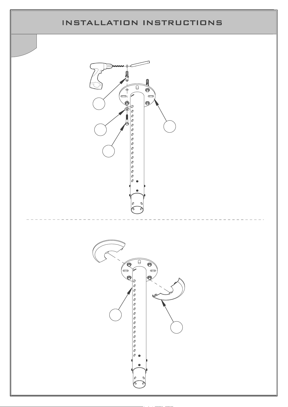
1
Attach Ceiling Pole Mount to Ceiling
i. Fix item 1 to the ceiling.
A3
A2
ii. Attach item 2 to item 1.
1
A1
1
2
6
Page 7
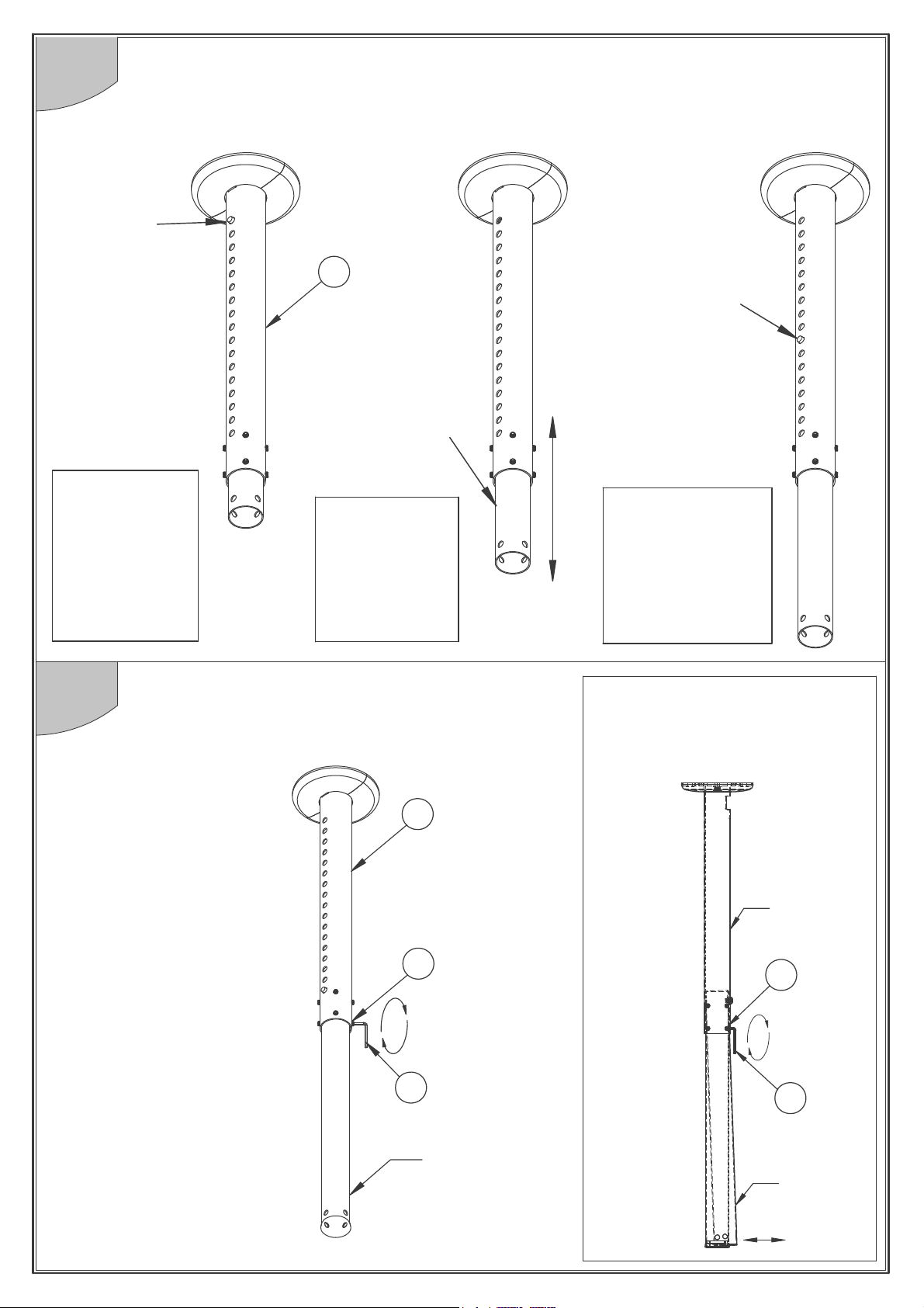
2
Adjust Ceiling Drop to Desired Height
i. Push spring button to
release height adjustment.
Push spring
button in
WARNING
Once button is
pushed in, the
inner pole will
fall to maximum
extension if not
held.
ii. Move inner sliding pole
to desired ceiling drop.
1
Inner
Sliding Pole
WARNING
When selecting
height, keep
fingers clear of
safety slot on
reverse of pole.
iii. When desired ceiling drop is
reached, ensure spring button
protrudes from hole.
Spring Button
must protrude
fully from hole
WARNING
Ensure Spring
Button fully
protrudes from
desired hole before
any AV is attached.
3
Fix Inner Sliding Pole in place
Tighten item 3 using item 20 to ensure the inner
sliding pole is fixed securely in position.
1
3
20
Note:
The angle of the
pole can
inner sliding
be adjusted using
item 3.
Outer
Pole
3
20
Inner
Sliding
Pole
Inner
Sliding
Pole
7
Page 8
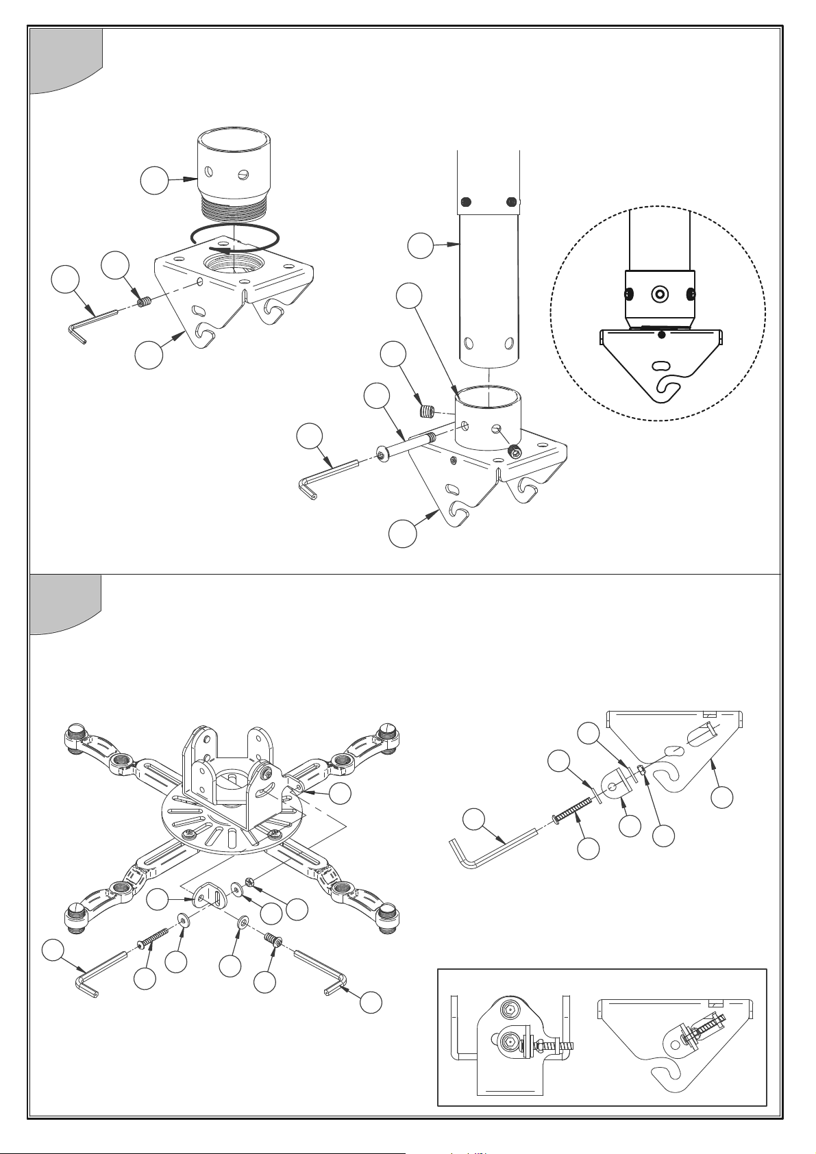
4
19
Attach Pole Adaptor Mount to Ceiling Pole Mount
Connect item 4 to item 1 using item 26.
26
1
18
26
5
i.
4
28
27
21
4
Optional Micro-adjustment
For short throw projectors the micro-adjustment can be installed as shown.
If the micro-adjustment is not required proceed to Step 6.
ii.
24
24
6
21
22
21
8
23
24
16
15
24
25
21
23
22
25
TiltRoll
4
Page 9
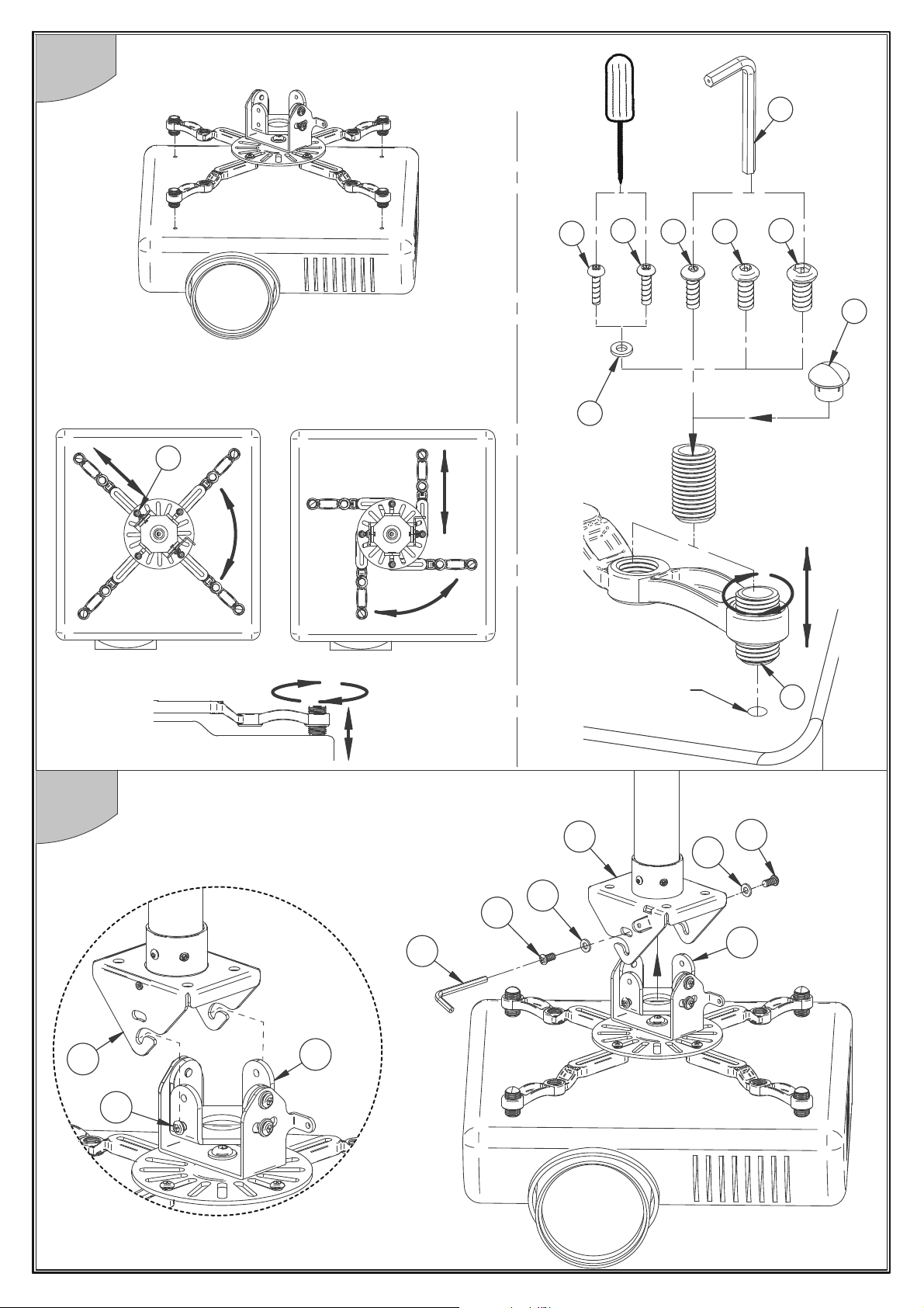
6
Attach Interface Assembly to Projector
21
Loosen part 15, adjust legs then re-tighten.
15
A
MOUNTING HOLE
B
F
C D
E
10
9
7
Hook Projector onto Ceiling Mount
Connect item 5 to item 4 using items 15 & 16.
4
16
15
21
4
15
5
15
16
5
9
Page 10
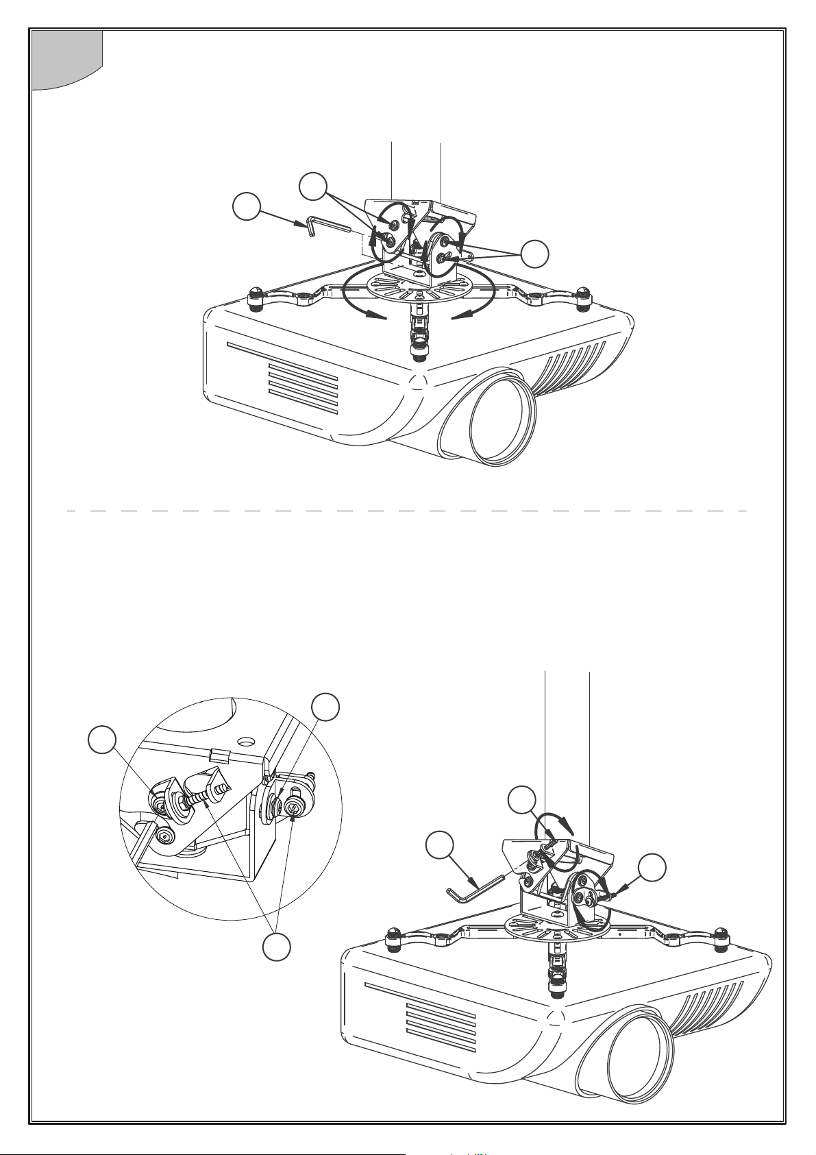
8
i) To tilt/roll, loosen items 15, adjust and re-tighten.
Adjusting the Projector
15
21
15
ii) Micro-adjustment (if installed).
Loosen item 15 (M6 x 12mm screws) by one turn using item 21.
Micro adjust item 23 (M4 x 30mm screws) using item 21 to roll or tilt the projector.
M6 x 12mm
Screw
M6 x 12mm
Screw
15
15
23
Tilt
21
23
Roll
23
10
M4 x 30mm
Screws
Page 11
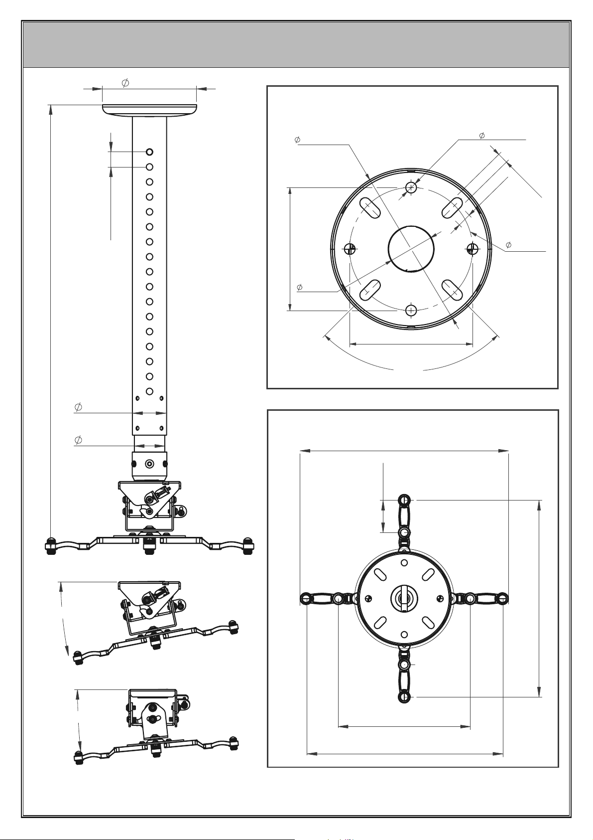
157.5mm
BT899-AD
PRODUCT DIMENSIONS
CEILING PLATE
16 x 25mm
Min:743mm - Max:1143mm
57.3mm
157.5mm
120mm
44mm
120mm
90º
4 x
10.5mm
10.5mm
13.5mm
120mm
50.8mm
+ / - 13º pitch
PROJECTOR MOUNTING PLATE
400mm
55mm
A
Max: 370mm
+ / - 6º roll
THESE INSTRUCTIONS ARE INTENDED AS A GUIDE ONLY AND B-TECH ACCEPTS NO
LIABILITY FOR THE ACCURACY OF THE INFORMATION CONTAINED IN THIS DOCUMENT.
260mm
Max: 370mm
11
Page 12

www.btechavmounts.com
B-TECH AV MOUNTS
HEAD OFFICE
B-Tech International Limited
Bennett House, Long March, Daventry, Northants., NN11 4NR, UK
Email: [email protected]
©2019 B-Tech International Design and Manufacturing Limited. All rights reserved.
B-Tech AV Mounts is a division of B-Tech International Design & Manufacturing Ltd.
B-Tech, Better By Design, System 2 and Pro Install are registered trademarks of B-Tech International Design & Manufacturing Ltd.
All other brands and product names are trademarks of their respective owners.
Photographs are for illustrative purposes
AMA-BT899-AD-V1-0819-03 MADE IN P.R.C.
only. E&OE.
 Loading...