

Page 1

BT8706
B-TECH AV mounts
PREMIUM FREESTANDING
SINGLE SCREEN UC STAND
INSTALLATION GUIDE
SPECIFICATIONS
• Recommended for screens up to: 70" (177cm)
• Max load: 70kg (154lbs)
• Suitable for displays with xings up to 672 x 400mm
• Stand dimensions: H.1945 x W.828 x D.756mm
• Universal design suitable for displaying screens
in a landscape or portrait orientation
• Integrated cable management
www.btechavmounts.com
Page 2
CONTENTS
Installation Safety Notes......................................................................................................................
Parts List....................................................................................................................................................
Installation Instructions.......................................................................................................................
Product Dimensions............................................................................................................................
B-Tech Contact Details........................................................................................................................
2
4
6
11
12
INSTALLATION SAFETY INSTRUCTIONS
This stand is intended for use only with the
CAUTION:
maximum weights indicated. Use with screens heavier than the maximum
indicated may result in instability causing possible injury.
Do not attempt to install this product until all instructions and warnings have been read and properly understood.
Please keep these instructions for future reference.
Please check carefully to make sure there are no missing or defective parts - defective parts must never be used.
B-Tech AV Mounts, its distributors and dealers are not liable or responsible for damage or injury caused by improper
installation, improper use or failure to observe these safety instructions. In such cases, all guarantees will expire.
General
r suitab
B-Tech AV Mounts recommends that a professional AV installer or othe
Great care must always be taken during installation as most AV equipment is of a fragile nature, possibly heavy and
easily damaged if dropped.
If you do not fully understand the instructions or are not sure how to install this product safely, then please consult a
professional for advice and/or to install this product for you. Failure to mount this product correctly may cause serious
on and
injury or death both during installati
Do not mount any AV equipment that exceeds the specic weight limit of the product you are installing.
This weight limit will be clearly stated on each product and its packaging and will vary from product to product.
at any time thereafter.
ly qualied person install this product.
Product location
Please pay careful attention to where this product is located. Check load capacity of oor prior to installation as some
surfaces are not suitable for installation. Designed for indoor use, this mount is suitable for public or home installation
If located in a public or frequently populated area ensure that the product is out of the immediate reach of people.
If any AV equipment is to be suspended over the likely path or location of people then great care should be taken to
secure all parts of the installation from falling.
When drilling holes it is essential to avoid contact with electrical cables and water or gas pipes contained within.
Use of a good quality live wire detector and hidden object locator is therefore recommended.
Only drill into structures when you are sure it is safe to do so.
Fixing hardware
It is highly recommended that all xing screws be used where supplied and that the purpose of all other xing hardware
is fully understood. In some cases more AV equipment xing hardware will be supplied to accommodate dierent models
of equipment and set up congurations. The installer must be satised that any supplied xing hardware is suitable for
each specic installation. If any xing screws or included hardware are deemed not sucient for a safe installation then
lea
se consult a professional or your local hardware store.
p
Hazard limitation
When routing cables take advantage of any built in cable management features that the product might provide and ensure
that all cables are tidy and secure. Check to see that any moving aspect of the product can do so unhindered by any cabling.
Some products have moving parts and the potential to cause injury through the crushing or trapping of ngers or other
body parts.
during set up.
necessary xings are present and are of ample tightness.
It is recommended that periodic inspections of the product and its xing points are made as frequently as possible (no more
than 6 months apart) to ensure that safety is maintained.
If in doubt consult a professional AV installer or other suitably qualied person.
Particular attention to the nature of moving parts is required especially when assembling installing and adjusting
Immediately after installation double-check that the work done is safe and secure. Double-check all
2
Page 3
Page 4
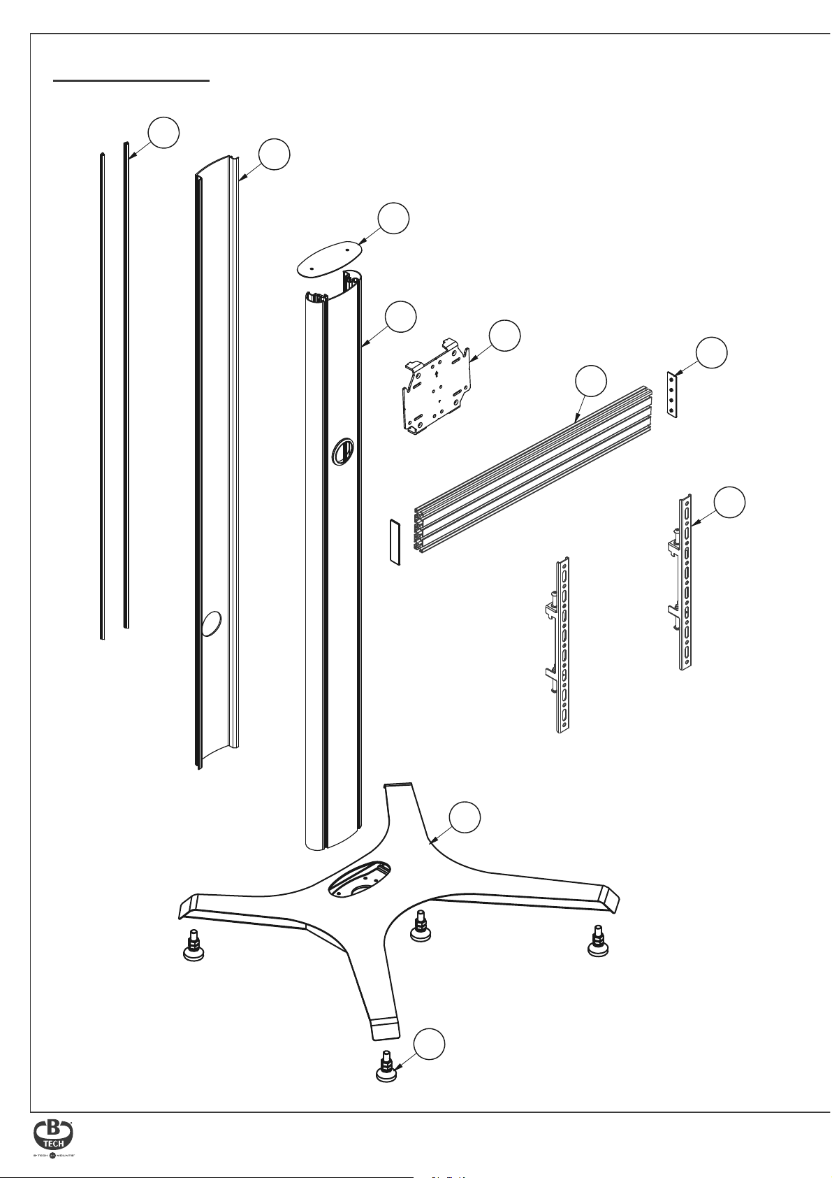
BT8706 PARTS LIST
PLEASE KEEP THIS FOR FUTURE REFERENCE
A7
A3
A2
A1
C1
D2
D1
B1
E1
B2
4
Page 5
E3
E8
E12
B5
C2
A4
E4
A8
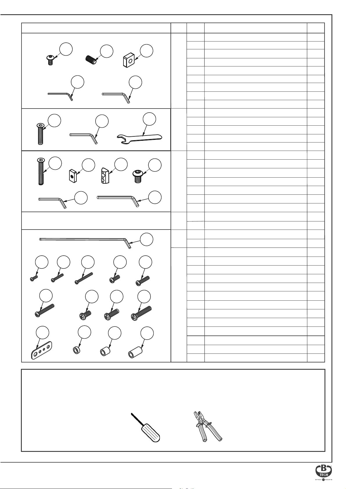
ITEM REFPART DESCRIPTION QTY
A1
1.9M COLUMN
END CAP
A2
A3
COLUMN REAR COVER
M6 x 12mm HEX SCREW
A4
A5
M6 x 12mm GRUB SCREW (OPTIONAL)
COLUMNBASEMOUNTING BRACKET
A6
SQUARE NUT (OPTIONAL)
COVER STRIP
A7
A8
3AF HEX KEY
4AF HEX KEY
A9
B1
BASE
B2
ADJUSTABLE LEVELLING FEET
M6 x 30mm CSK HEX SCREW
B3
4AF HEX KEY
B4
19mm SPANNER
B5
RAIL-TO-COLUMN MOUNTING BRACKET
C1
M6 x 40mm CSK HEX SCREW
C2
C3
RECTANGLE NUT
M8 SLIDING INSERT
C4
M8 x 12mm SCREW
C5
4AF HEX KEY
C6
5AF x L120mm HEX KEY
C7
MOUNTING RAIL
D1
RAIL
D2
END CAP
SCREEN INTERFACE ARM
E1
ARMS
E10
SCREEN FIXING KIT
E11
E12
E13
E14
E15
5AF LONG HEX KEY
E2
E3
M4 x 12mm SCREW
M4 x 25mm SCREW
E4
M4 x 40mm SCREW
E5
M6 x 16mm SCREW
E6
E7
M6 x 25mm SCREW
M6 x 40mm SCREW
E8
M8 x 16mm SCREW
E9
M8 x 25mm SCREW
M8 x 40mm SCREW
MULTIWASHER
5mm SPACER
13mm SPACER
24mm SPACER
C6
E13
C3
E5
E9
B4
A5
E10
E14
C4
E6
A6
A9
B5
C5
C7
E2
E7
E11
E15
1
1
1
2
4
4
4
1
1
1
4
4
1
1
1
4
4
4
4
1
1
1
2
2
1
4
4
4
4
4
4
4
4
4
4
4
4
4
INSTALLATION TOOLS REQUIRED
Crosshead screwdriver
Pliers/Cutter
5
Page 6
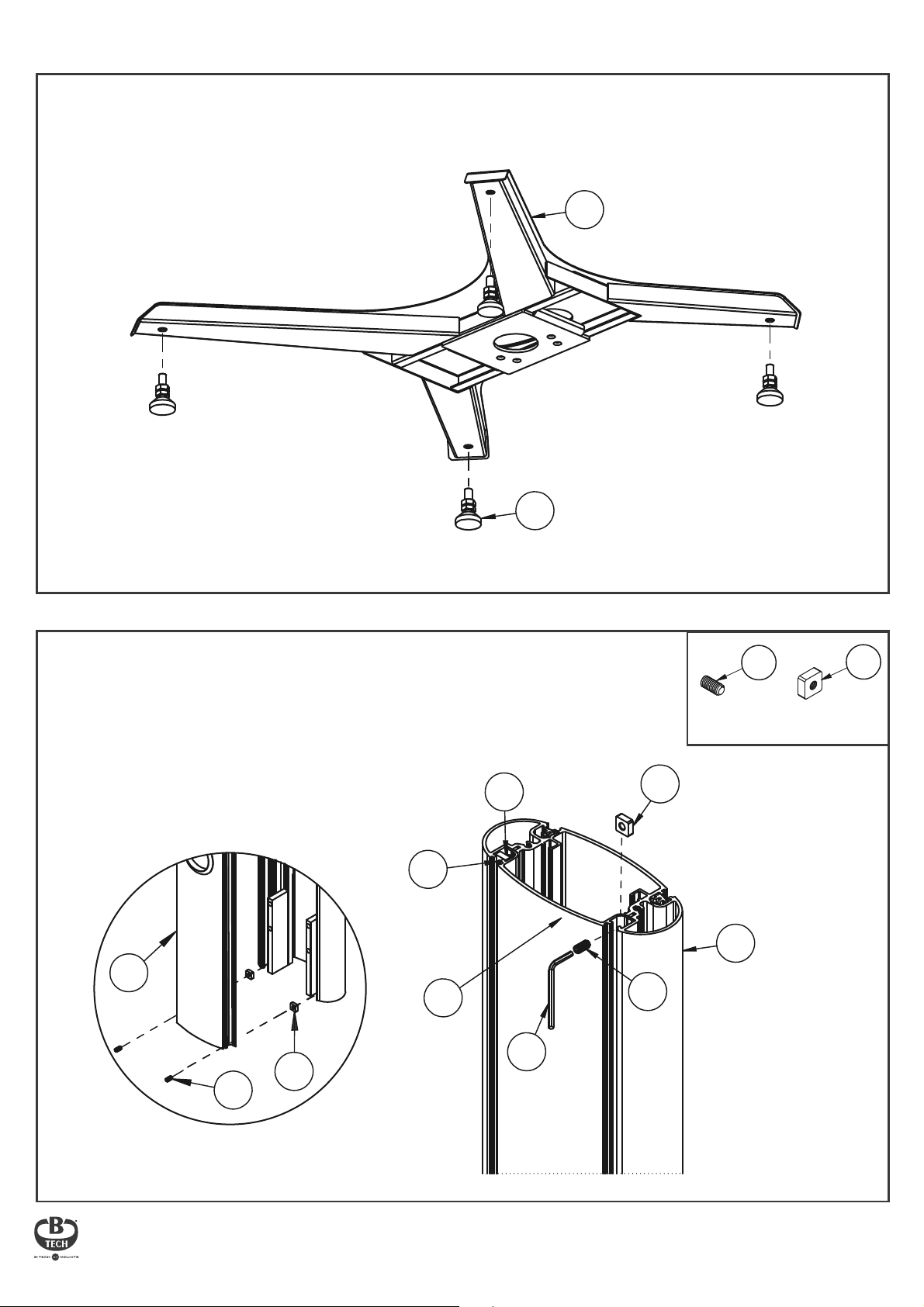
Installation Instructions
FIX FEET TO BASE
1.
Attach item B2 to the bottom of item B1.
B1
OPTIONAL - FIX REAR COVER TO COLUMN
Place item A3 into the back of item A1.
Use items A5 & A6 at the top and bottom of the
column slot to secure rear cover.
A5
REAR
A6
B2
A6
FRONT
A5
M6 x 12mm
GRUB SCREW
A1
A6
SQUARE
NUT
A3
A5
REAR
A6
A3
A5
A8
6
Page 7
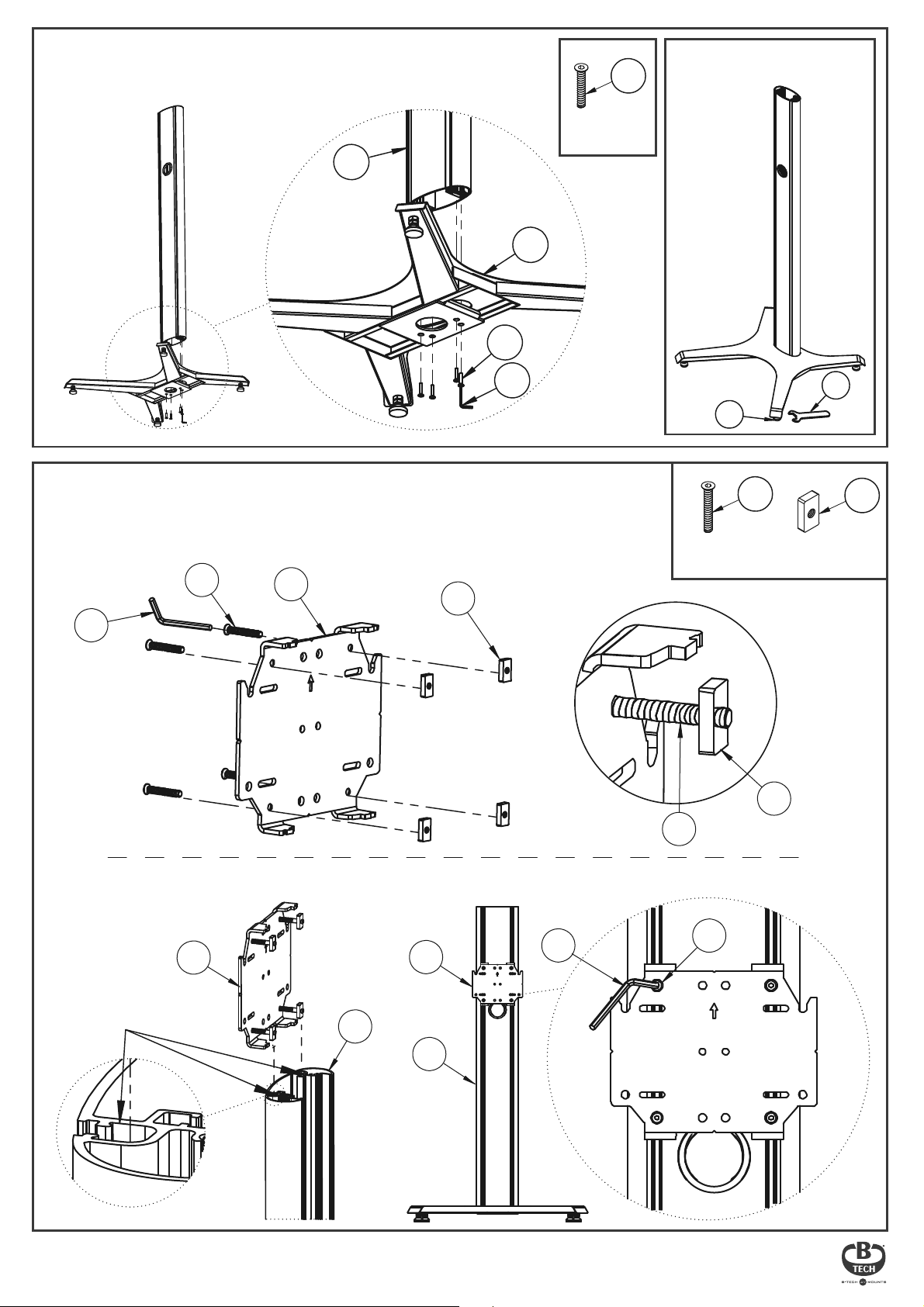
ATTACH COLUMN TO BASE
2.
Fix item A1 to the top of item B1 using item B3.
A1
B3
B1
B3
M6 x 30mm
CSK HEX SCREW
OPTIONAL: To level the stand,
adjust item B2 using item B5.
ATTACH MOUNTING BRACKET TO COLUMN
3.
i. Insert 4 x item C2 into item C1 and attach item C3.
Screw two full turns to leave item C3 at the end of item C2.
C2
C6
C1
C3
B4
B2
M6 x 40mm
CSK HEX SCREW
C2
C2
B5
C3
RECTANGLE
NUT
C3
ii. Slide item C1 down the front slots of item A1 to the correct height and tighten item C2.
C6
SLOTS
C1
C1
A1
A1
7
C2
Page 8
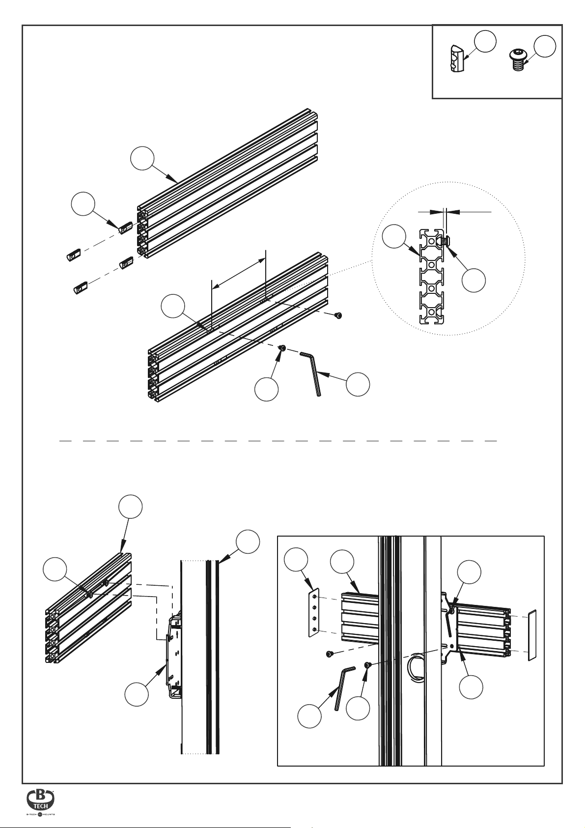
HOOK RAIL ONTO MOUNTING BRACKET
4.
i. Insert 4 x item C4 into item D1 (2 in the top channel, 2 in the bottom channel).
ii. Screw 2 x item C5 into item C4 in the top channel - allow at least a 6mm gap
so the rail can be hooked on to item C1.
D1
M8 SLIDING
INSERT
C4
C5
M8 x 12mm
HEX SCREW
C4
185mm
C4
C5
iii. Hook item D1 onto item C1 and x with in place with item C5.
iv. Attach item D2 to the ends of item D1.
6mm+
D1
C5
C7
C5
D1
C1
A1
D2
C7
D1
C7
C4
C5
8
Page 9
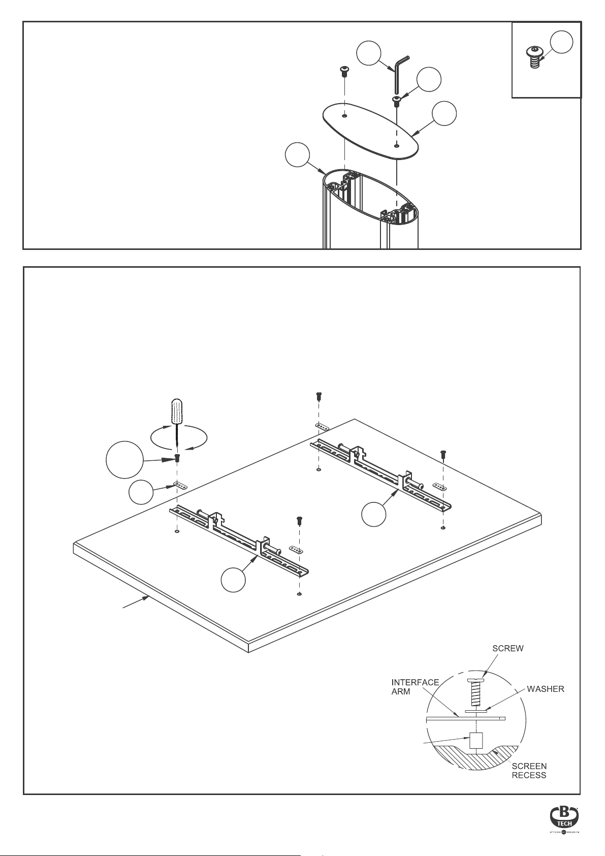
FIX END CAP TO COLUMN
5.
Fix item A2 onto the top of item A1
using item A4.
A1
A8
A4
A2
TOP
ATTACH INTERFACE ARMS TO SCREEN
6.
Fix item E1 to the rear of the screen using items E3 - E15.
Note: Ensure the arms are facing the correct way round and the same holes are used on both arms.
A4
M6 x 12mm
HEX SCREW
E3-E11
SCREEN
E12
TOP
E1
E1
BOTTOM
Use spacers (items E13-E15)
for screens with recessed xings.
9
Page 10
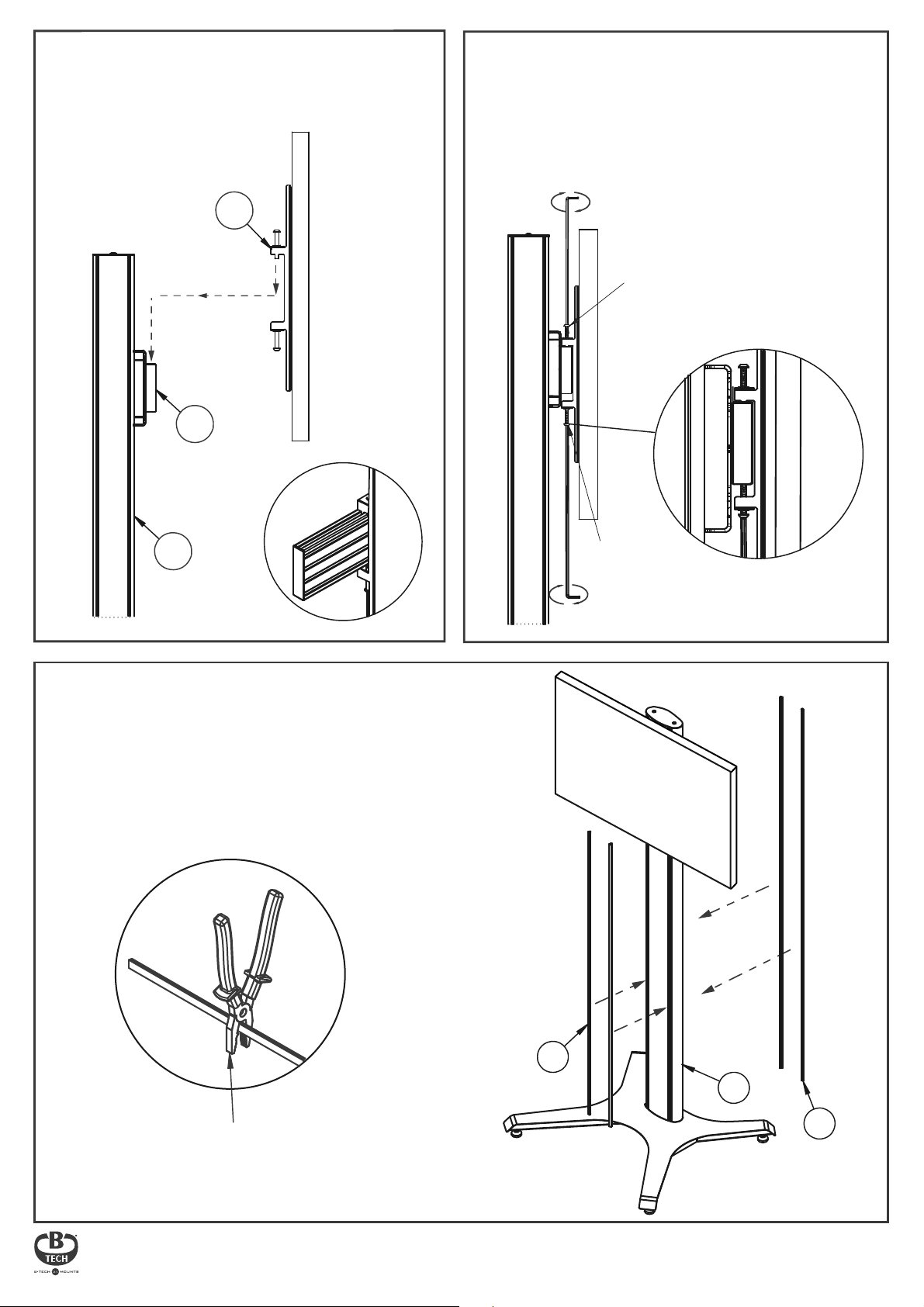
HOOK SCREEN ONTO RAIL
7.
Use items E1 to hook the screen
onto item D1.
E1
D1
SCREEN
LOCK SCREEN TO RAIL
8.
Tighten the safety screws on the bottom
of item E1 securing the screen to item D1.
Note: If necessary, adjust the height adjustment
screws on top of item E1 to level the screen.
Optional:
HEIGHT ADJUSTMENT
SCREW
SCREEN
SCREEN
A1
ATTACH STRIPS
9.
Insert item A7 to the front and back of item A1.
Note: Item A7 may have to be cut down to size
to be able to t into the front of item A1.
SAFETY
SCREW
Safety Screw
Engaged
Use pliers to cut item A7
to correct size
A7
A1
A7
10
Page 11
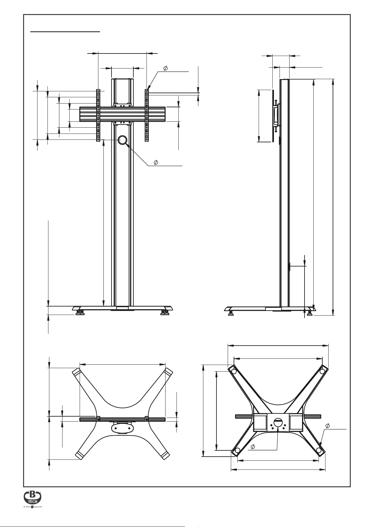
BT8706 DIMENSIONS
PLEASE KEEP THIS FOR FUTURE REFERENCE
FRONT VIEW SIDE VIEW
400mm
200mm
300mm
100mm
Max 672mm
180mm
1366.5mm
60.8mm
8.4mm
20mm
120mm
138.5mm
428mm
79.5mm
1900mm
1945mm
71.5mm + 10mm adjustment
TOP VIEW
705mm
398.5mm
42mm
357mm
30mm
649.3mm
755.5mm
70mm
BOTTOM VIEW
828mm
727.8mm
669mm
777.1mm
328.5mm
40mm
These instructions are intended as a guide only and B-Tech accepts no liability for the accuracy of the information contained in this document.
11
Page 12
B-TECH AV mounts
CONTACT:
©2020 B-Tech AV Mounts. All rights reserved.
B-Tech AV Mounts is a division of B-Tech International Design and Manufacturing Ltd.
B-Tech AV Mounts and the B-Tech logo are registered trade marks.
All other brands and product names are trademarks of their respective owners.
Photographs are for illustrative purposes only. E&OE.
For More Information Visit www.btechavmounts.com
 Loading...