

Page 1

B-TECH AUDIO VIDEO MOUNTS
www.btechavmounts.com
CONTENTS
INSTALLATION TOOLS REQUIRED
FEATURES
BT33
HOME CINEMA SPEAKER WALL MOUNT
INSTALLATION GUIDE & PARTS LIST
This Pack Contains 1 Speaker Mount
Installation Safety Instructions............................................................................................................2
Parts List.............................................................................................................................................4
Installation Instructions.......................................................................................................................6
Product Dimensions..........................................................................................................................11
B-Tech Contact Details.....................................................................................................................12
Crosshead /
Flathead screwdriver
Drill
6mm (1/4") masonry bit
or 3mm (1/8") wood bit
Pencil
Level
(optional)
Stud finder
(optional)
REG DESIGN NO: 3007645
PATENT NO: 1546599
US PATENT NO: 7523906
● Designed for small home cinema speakers weighing
up to 5kg (11lbs)
● Mounts speaker only 72mm (2.8”) from wall
● Suitable for single point, dual point and keyhole fixings
● Distance between dual point fixings:
51 – 67mm (2” – 2.6”)
● Suitable for speakers using M5, M6, UNC ¼” &
Wood Screws
● Simple installation with all mounting hardware included
PLEASE KEEP THIS FOR FUTURE REFERENCE
Page 2

4
BT33
PARTS LIST
7
9
1
2
3
4
5
8
6
Suitable for loads up
to 5Kg (11lbs)
Page 3

5
PLEASE KEEP THIS FOR FUTURE REFERENCE
REF PART NAME QTY
1 TOP BALL CLAMP 1
2 WALL PLATE 1
3 BOTTOM BALL CLAMP 1
4 BALL INTERFACE 1
5 ADAPTOR INTERFACE 1
6 M6 x 12mm SCREW (FOR PART 5) 1
7 M6 x 40mm SCREW 1
8 M6 METAL WASHER (FOR PART 7) 1
9 M3 x 8mm SCREW 1
INTERFACE KIT
A M5 x 12mm SCREW 2
B M6 x 12mm SCREW 2
C UNC 1/4” x 5/8” SCREW 2
D M4.2 x 19mm WOOD SCREW (No.8 X 3/4”) 2
E KEYHOLE INSERT 1
FIXING KIT
A1 M4.8 x 32mm WOOD SCREW 2
A2
No 6 WALL PLUG
(FOR PART A1)
2
C
B
A
D
E
A2
A1
SPEAKE R INTERFA CE KIT
(FOR ATTACHING MOUNT TO
BACK OF SPEAKER)
WALL FIXING KIT
(FOR FIXING MOUNT TO WALL)
Page 4
6
1
INSTALLATION INSTRUCTIONS
A/B/C
A/B/C
4
REAR OF
SPEAKER
6
5
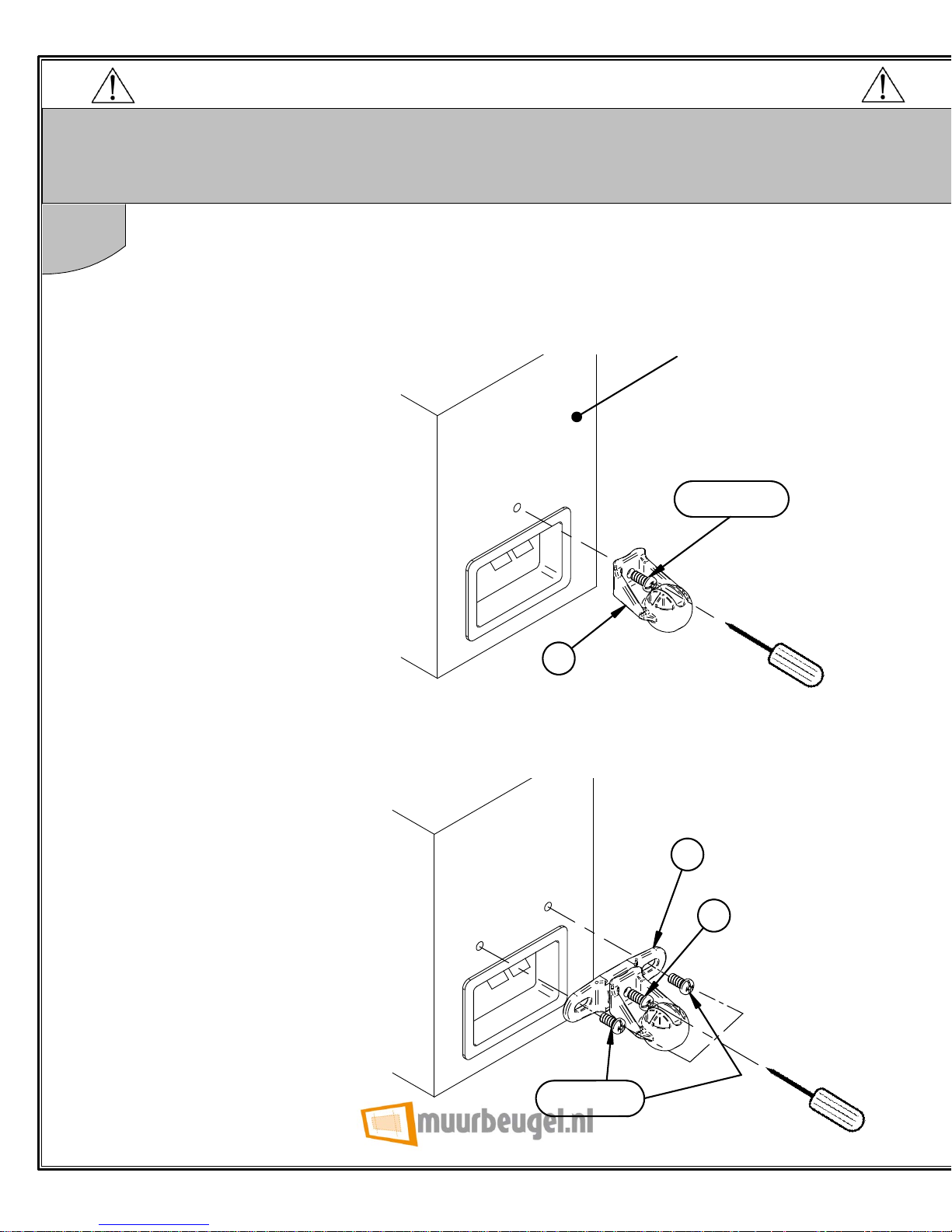
Choose one of the four fixing methods shown that suits your speaker
fixings.
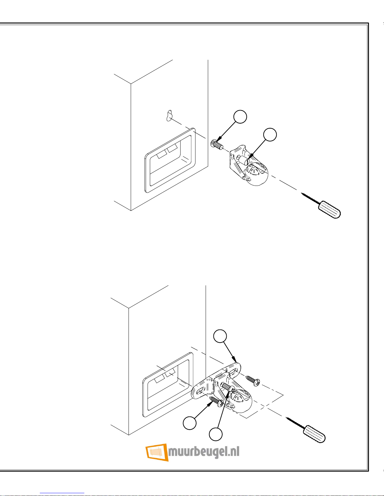
Attach part 4 to the speaker using screws A, B, C or D, or for
keyhole fixings use screw A and part E.
i. Single threaded insert.
ii. Dual threaded insert.
THIS MOUNT MUST BE DISASSEMBLED PRIOR TO INSTALLATION
Page 5
7
iii. Keyhole insert.
A
E
iv. No insert.
D
5
6
Page 6
8
2
3
4
1
8
7
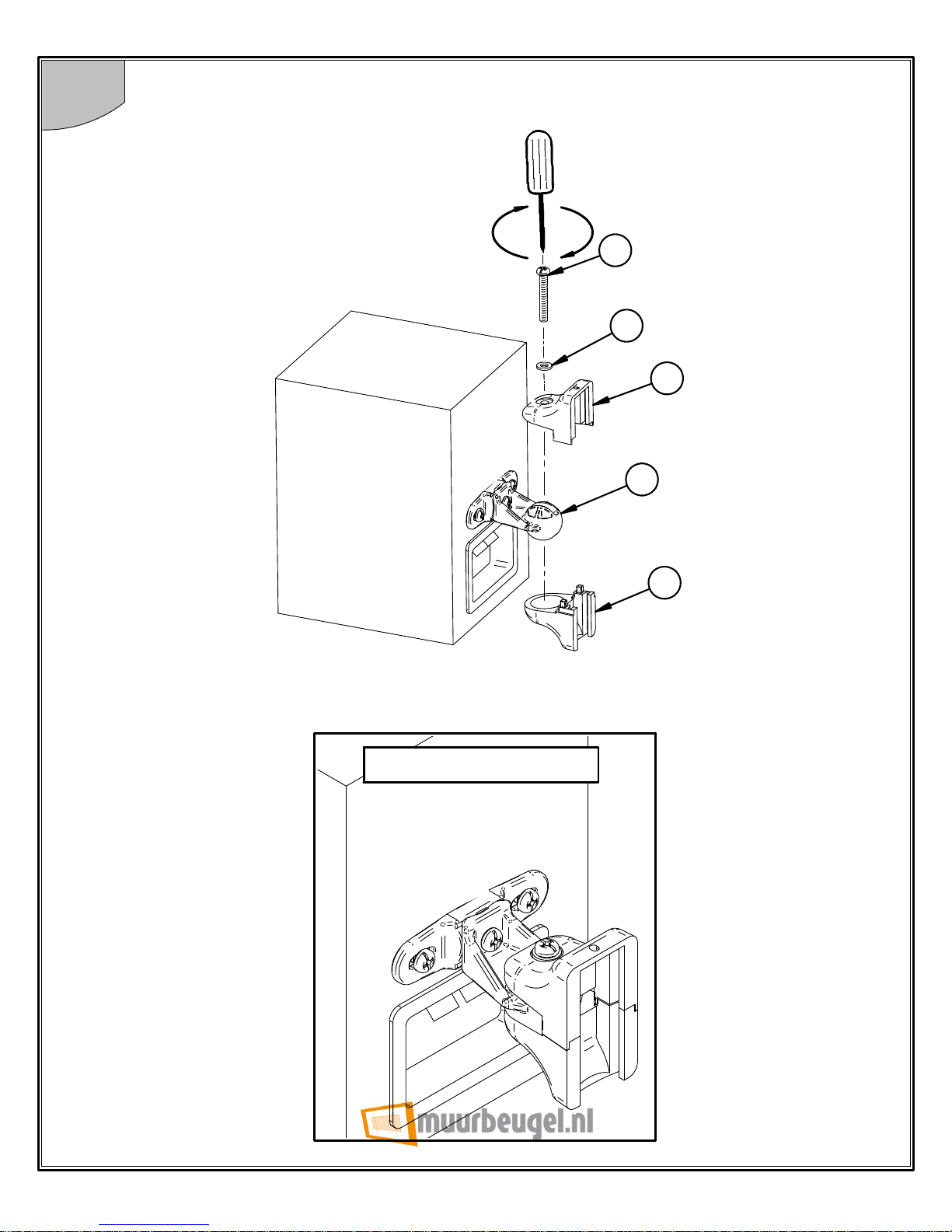
Attach parts 1 & 3 to part 4 using parts 7 & 8.
ASSEMBLED VIEW
Page 7
9
3
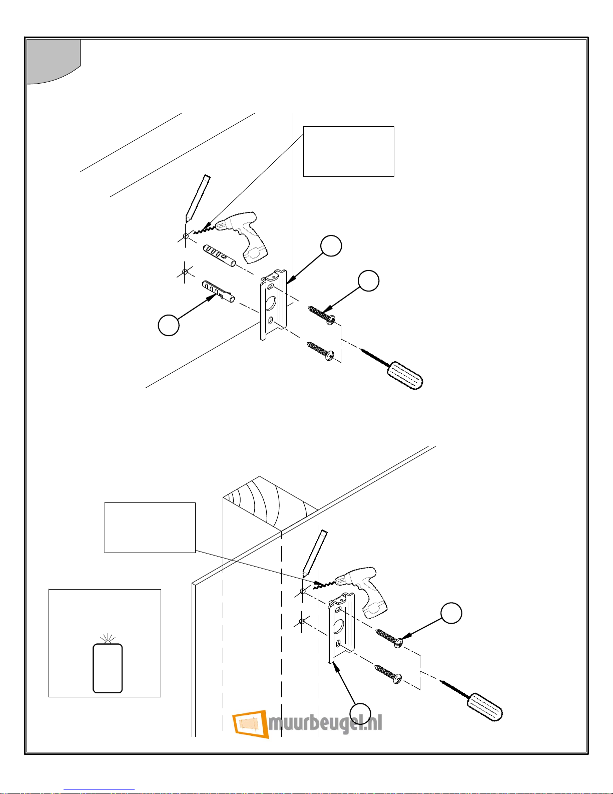
Fix part 2 to the wall using one of the two methods shown.
A2
A1
2
A1
2
i. Brick / concrete walls.
ii. Wood / wood stud walls.
6mm (1/4")
masonry bit
3mm (1/8")
wood bit
STUD FINDER
(Optional)
Page 8
10
4
5
6
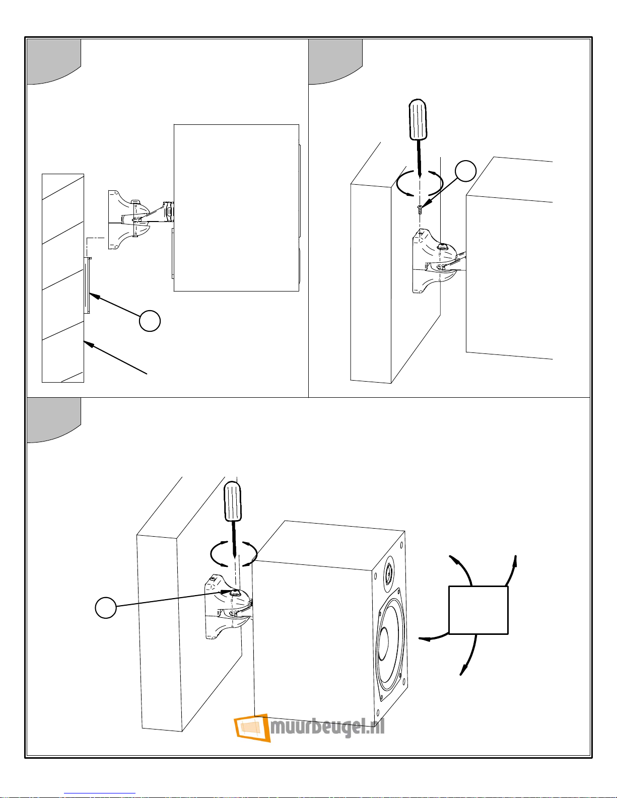
Hook the mount onto part 2.
To adjust the tilt and swivel, slightly loosen part 7 then adjust the speaker
position. Finally, retighten part 7 to fix the speaker position.
7
Tilt &
swivel
WALL
2
Secure the mount to part 2
using part 9.
9
Page 9
11
BT33
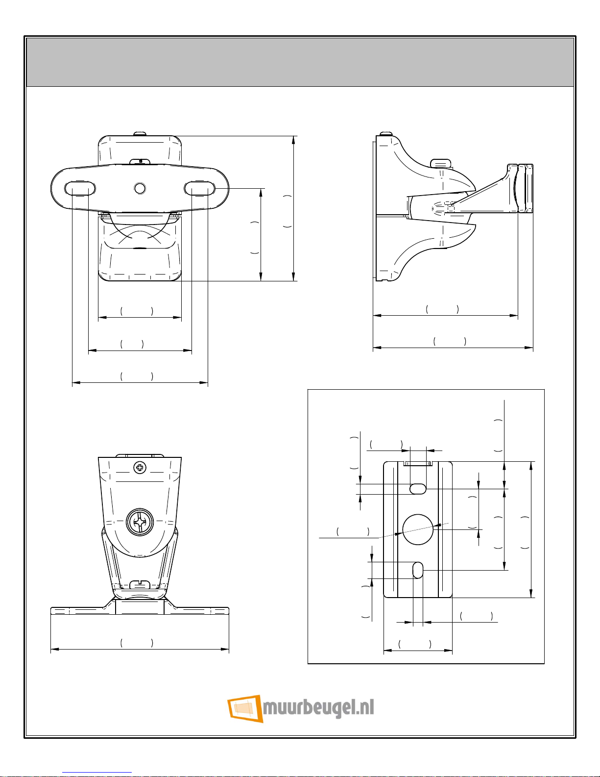
PRODUCT DIMENSIONS
These instructions are intended as a guide only and B-Tech accepts no
liability for the accuracy of the information contained in this document.
46mm
1.8"
72mm
2.8"
79mm
3.1"
72mm
2.8"
88mm
3.5"
41mm
1.6"
67mm
2.6"
51mm
2"
34mm
1.3"
67mm
2.6"
O
15mm
0.6"
20mm
0.8"
8mm
0.3"
8mm
0.3"
WALL PLATE
5mm
0.2"
5mm
0.2"
40mm
1.6"
13.5mm
0.5"
 Loading...