

Page 1

INSTRUCTION BOOK
Page 2
INTRODUCTION
2
BUILDING INSTRUCTIONS FOR THE
WRITTEN BY BRUCE THARPE
Instruction Book Version 5
Proudly Manufactured in the USA by
BRUCE THARPE ENGINEERING
8622 E EVANS CREEK ROAD
ROGUE RIVER, OR 97537
Information: 541-582-1708
Orders: 800-557-4470
www.btemodels.com
Questions? Call BTE or email
WING SUBASSEMBLIES
WING PANELS
WING PANEL DETAILS
JOINING THE WING PANELS
TAIL SURFACES
FUSELAGE SUBASSEMBLIES
FUSELAGE CONSTRUCTION
WING AND TAIL MOUNTING
TAIL PUSHRODS
FINISHING THE FUSELAGE
FUEL SYSTEM INSTALLATION
TURBINE INSTALLATION
RETRACT INSTALLATION
RADIO INSTALLATION
PRE-FLIGHT SETUP
FLYING TIPS
RECOMMENDED EQUIPMENT
OPTIONAL ACCESSORIES
2-VIEW DRAWING AND SPECS
5
7
11
13
14
16
18
21
23
25
28
30
31
32
33
34
35
37
38
COMPLETE PARTS LIST
39
Page 3
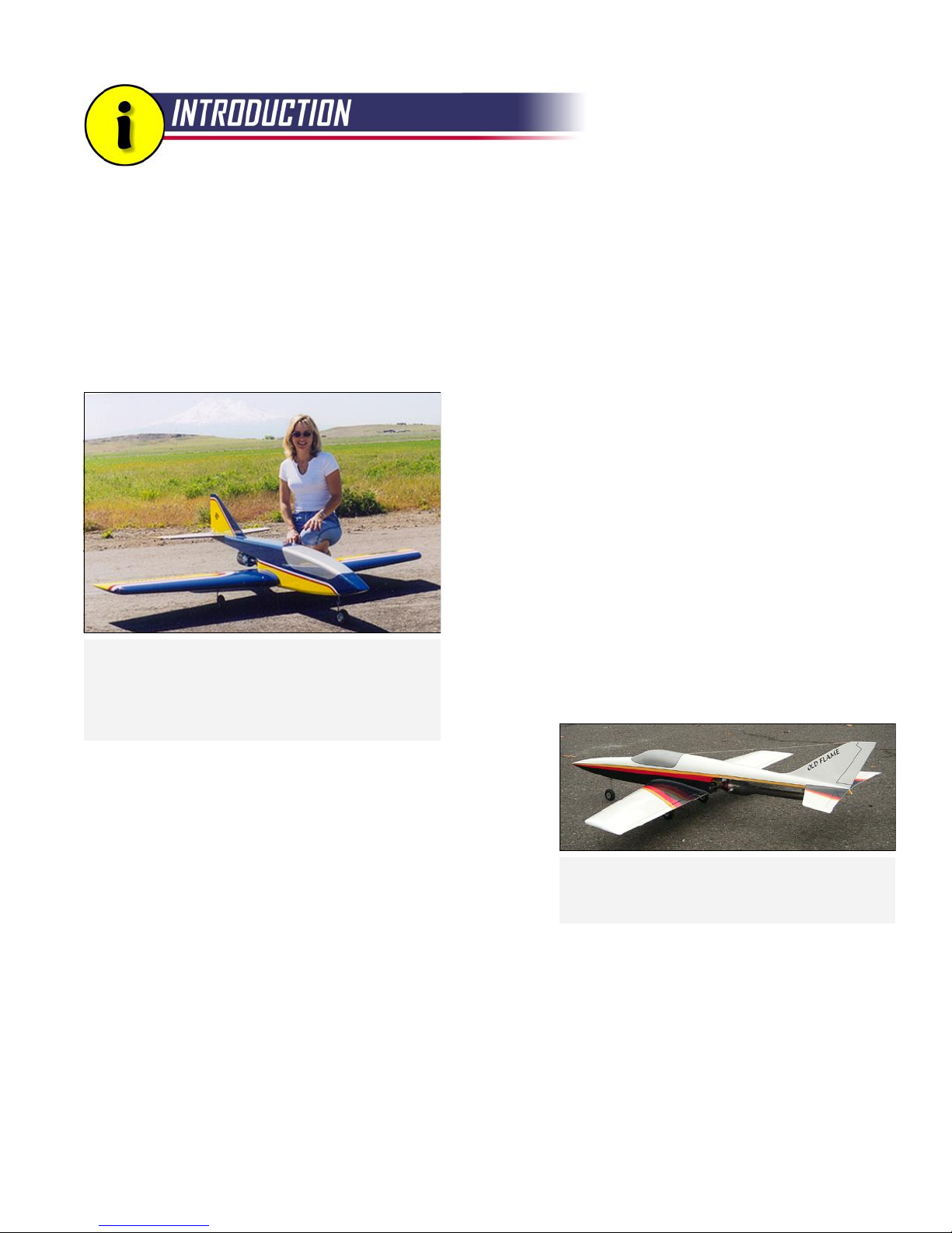
Thank you for selecting the Reaction 54 kit from BTE! The R54 is an entry-level R/C turbine model
utilizing traditional wood construction. A lot of effort has gone into the engineering of this kit to make
it an enjoyable and satisfying project from the first drop of glue to the first landing. It has always been
a goal of BTE to produce kits that are just as pleasurable to build as they are to fly.
Welcome
If you are new to turbines, welcome to the pinnacle of recreational R/C modeling. You have no doubt worked your
way up from trainers to sport models to aerobatic ships. Perhaps you've gained some quality stick time with racers or
ducted fan models as well. Those are all cool in their own way, but in my opinion at least, there is nothing like the thrill
of piloting a model propelled by the raw power of a miniature
gas turbine. There is something very pure about a turbine
model in flight. The lack of torque and general aerodynamic
cleanliness combine to produce a smooth, almost silky,
performance. And oh, that sound! When you taxi onto the
runway and move the throttle stick forward, you know
something special is about to happen. We're talking serious
goosebumps.
If you are an experienced jet pilot, you will find the R54 is a
refreshing and relaxing alternative to the high-buck, highmaintenance, high-stress turbine models that you may be used
The Moment of Truth! Bruce's sister, Susan, poses
with the prototype Reaction 54 moments before its
maiden flight at the Siskyou County Airport in northern
California. Look close and you can see the faint
outline of Mount Shasta in the background.
to. It will probably be your slowest turbine model, but if the
R54 fills the roll of your "everyday" jet, then I will consider that
a success. Sometimes it's not about the speed, it's about the
spirit.
My Background
I came to the world of turbines in a different fashion than most. My
previous jet experience came from designing, building, and flying
sport R/C models powered by pulsejet engines. My father
introduced me to the famous Dyna-Jet Redhead many years ago,
and they have always held a certain fascination with me. Anyone
who has heard the incredible roar of a Dyna-Jet never forgets it!
The inspiration for the general configuration of the
Reaction 54 goes back to this Dyna-Jet powered
model, the Old Flame.
As you may know, pulsejets are incredibly loud, run very hot, have
no throttle, and can be temperamental. Oh, did I mention they are incredibly loud? Every landing with a pulsejet
model is deadstick, so most of my designs featured big wings so they would glide well. Speed was never a priority. In
fact, efforts were made to keep the speed down because I prefer close-in flying. This design philosophy, to a certain
extent, was translated to my first turbine model, the R54.
About the Reaction 54 Design
My father and I built a number of pulsejet models dating back to the 1990’s. One of those models, our Old Flame, was
perhaps the best pure flyer of the bunch. The overall configuration of the R54 borrows heavily from the Old Flame in
that it features a low wing with the engine mounted under the rear part of the fuselage. On the next page is a list of
the other major design considerations for the R54...
2
Page 4

INTRODUCTION, continued...
All Wood - I'm comfortable with traditional wood design, and I figure so are a lot of potential modelers looking to get
into jets. Besides, being all-wood helps it stand out in the jet market that is dominated by composite designs.
Big and Light - Big models are easy to see, and light models are delightful to fly. Bigness helps keep the top speed
down, and lightness helps keep the landing speed down. A big fuselage gives you plenty of room for all that "stuff"
that turbine models need to haul around. A big, thick wing is inherently strong and gives you plenty of room for
retracts. Light weight gives you vertical performance and reduces landing gear loads.
Retracts - In my opinion, there has been a tendency to make entry-level turbine models too simple. Aspiring turbine
pilots have above-average skills and don't need to step back to a basic trainer. The R54 is still a fairly simple design,
but I want it to serve modelers well as a stepping stone to faster, more-complex turbine models. Retracts are part of
the jet scene, and the R54 just wouldn't look right without them.
Exposed Engine - I saved my pennies for several years to buy my first turbine engine, and didn't want to bury it inside
an airframe. Besides, an exposed engine is easy to work on and saves the weight, cost, and complexity of an exhaust
tube, inlets, and bypass. The R54 features an elegant streamlined area just ahead of the engine to help maintain
smooth airflow to the turbine inlet. For lack of a better term, I call this the "boat tail".
Low Cost - By definition, a turbine model will be expensive compared to most R/C models. Besides the engine itself,
the typical turbine model is expected to have custom-made composite fuel tanks, spring-loaded landing gear struts,
and special machined "jet" wheels. A major goal of the R54 was to keep the total cost low compared to other turbine
designs by using low-cost, off-the-shelf hardware items like the Du-Bro fuel tank, wire struts, and regular wheels. The
R54 blurs the line between your everyday sport model and what has become the norm in the turbine community.
Safety - The greatest safety feature of the R54 is that it's fairly slow by turbine standards and easy to fly. Care was
taken in the design to separate the fuel tank area from the turbine with a robust structure in the boat tail. A neoprene
pad is provided to cushion the front of the tank in an impact. The BTE prototype model has been thoroughly flight
tested and has proven itself to be a robust, well-behaved design that does what it is supposed to do, and does it well.
Things You Don't Normally See on Turbine Models
There are some design and equipment aspects of the R54 that you don't normally see on the typical turbine model.
To put your mind at ease, here is the reasoning behind some of my choices made during the development of the R54.
Push/Pull Cable Linkage for Rudder and Elevator - This might be the most unusual aspect of the design, but it has
proven itself in flight testing and on several of my earlier pulsejet designs. When installed as shown on the plans, you
will find the system makes for a very rigid, slop-free connection to the control surfaces. The servos are mounted up
front to keep the weight forward and are easy to access under the large hatch.
Easy Hinges - I love these hinges! They are economical and easy to install. Some might question their strength, but
that is addressed by using lots of them spaced fairly close together. If you go with plastic film, you don't even have to
worry about hinging until the model is completely covered.
Wire Landing Gear Struts - These aren't included in the kit, but they are supplied with the recommended retract
package. The struts on the R54 are short, so 3/16" wire is plenty stiff to handle the loads, even on grass. The R54
lands slow, so it doesn't need the cushioning of more expensive oleo-style spring struts.
3
Page 5

INTRODUCTION, continued...
Sport Wheels - A low-speed model like this doesn't need special, high-priced "jet" wheels. The 3" diameter Sullivan
and Hangar 9 sport wheels that I use handle rough terrain with no problem and the tires have never rolled off the rim
even after some bad landings with high side loads. And they are cheap to replace if necessary.
Electric Nose Wheel Brake - AMA requires brakes on turbine models. Again, considering the low-speed nature of
the R54, brakes aren't really necessary. The Kavan electromagnetic brake meets the AMA requirement, is relatively
inexpensive, is easy to install, and adds a little weight to the nose which you need anyway.
Bolt-On Wing - Modelers who have built my designs in the past know that I like to keep things simple. That's why the
R54 has a simple one-piece wing that bolts on like a normal sport model. This provides a solid center wing joint
without the extra complexity, weight, and cost of wing joiners. Besides, the finished wing is shorter than the fuselage,
so transporting is not a big issue.
Open Rib Bays - To drive home the sport model feel of this design, I went with some open rib bays near the tips. I've
seen film used on open structures on birds much faster than the R54. You can sheet the whole wing if you wish
(plenty of wood is provided in the kit), but in my opinion it's just extra weight.
Plastic Film Covering - Okay, this isn't totally uncommon on sport jets. Still, the R54 was designed with plastic film
covering in mind from the outset. Use a high-quality film like Monokote or Ultracoat, and be mindful of the orientation
of the seams in relation to the airflow.
Glues
General construction of most of the model can be done using Cyanoacrylate Adhesive (referred to as CA in the book).
BTE offers a package of high-quality Handibond CA tailored specifically to the R54. The instructions will, from time to
time, make suggestions as to the type of glue to use in certain steps. There are times when a good aliphatic resin like
Elmer's Wood Glue or Tite-Bond (referred to as "yellow glue" in the book) will be the best choice. Slow-dry epoxy (30minute or longer) is recommended for high-stress areas like the wing joint.
A Note About Craftsmanship
I keep referring to the sport nature of this model and my effort to keep it simple. Do not, however, lose sight of the fact
that this IS a turbine-powered model that can achieve high speeds and high in-flight air loads. I encourage you to take
your time with the construction, build it straight, and build it strong. Every effort has been made at BTE to produce
wood parts that fit well, but ultimately, the quality of the finished product is up to you. Approach the building process
with an attitude of "do it right" rather than "do it fast", and you will be rewarded with a unique R/C model that you can
truly be proud of.
Enough Already, Let's Build!
Okay, okay, but like all instruction book writers,
I am obliged to insist that you read through the
booklet completely before you start, and study
the plan sheets. Think ahead. Grab the glue.
Turn the page... R54
LIMIT OF LIABILITY
In use of our products, Bruce Tharpe Engineering's only obligation shall
be to replace such quantity of the product proven to be defective. User
shall determine the suitability of the product for his or her intended use
and shall assume all risk and liability in connection therewith.
Instruction Book Note for 2014
This book was originally written about ten years ago, and there have
been some major advancements in the hobby and turbine engines
since that time. We now have 2.4GHz radios, kero-start turbines,
electric retracts, and numerous other advances in equipment. But
balsa is still balsa and the science of aerodynamics remains
unchanged. So build your R54 as shown - there have been no
significant changes to the airframe since it was introduced. In later
chapters, you will see references to dated equipment, but the
examples presented there and your own experience should be
enough to guide you through. As mentioned at the left, think ahead!
4
Page 6
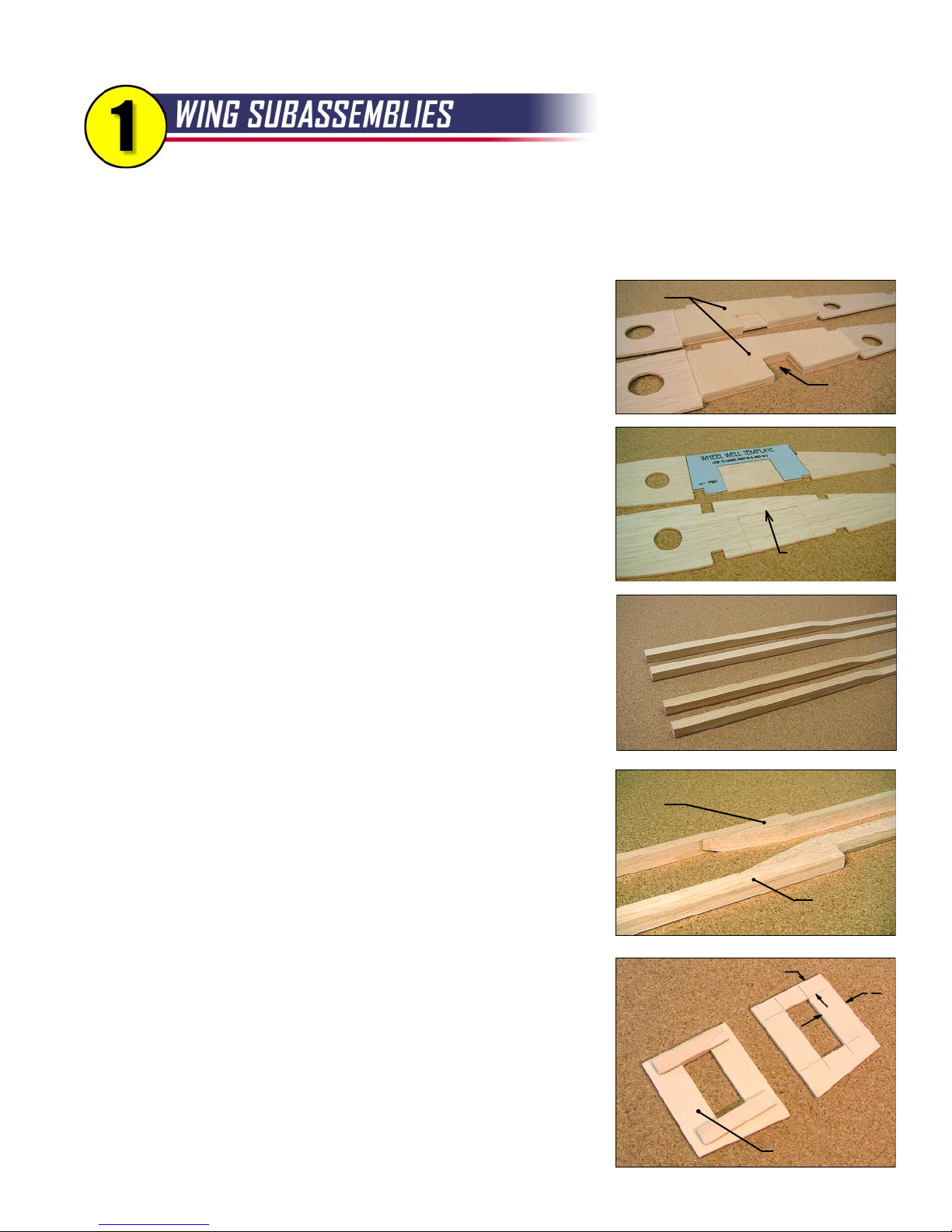
Once these time-consuming tasks are done, you'll be ready to fly through the assembly of the wing
panels with minimal delay. Let's roll...
Optional - If you plan on building your R54 with open rib bays, skip to the next step. If you plan on sheeting
your entire wing, you need to trim the W-13 wing ribs as shown on the plan.
Later, capstrip material will be added to the recessed edges to provide extra
W-6D
gluing area where the center sheeting meets the wingtip sheeting.
Glue a W-6D doubler to each side of both W-6 wing ribs. When dry,
cut away the exposed balsa as shown in the photo.
Cutout
Balsa
Cut out the Wheel Well Template (blue card stock) and use it to
mark the W-4 and W-5 wing ribs. Go ahead and cut the ribs along the upper
line, but only score the vertical lines for now. You will cut those later, after
the ribs are firmly glued into the wing structure.
Using the short notches as guides, mark the position of the dihedral
brace slots on the W-1, W-2, and W-3 wing ribs. Again, don't cut them yet -
Cut Here Only
the lines will help guide the cuts later when it's time to join the wing panels.
Main Spar Assemblies
You can tell the bottom main spars from the tops because the
bottom spars are beveled slightly on the front edge. The purpose of the
beveled edge is to provide a flat gluing surface for the shear webs. Locate
the two bottom main spars and the two 12" spruce bottom spar doublers.
Taper the outboard ends of the spar doublers as shown on the plans. Be
careful here - you need to make a left and a right! Glue the doublers to the
main spars, being sure to align the beveled edges.
Repeat the previous step for the top main spars. The top spars are
Right-Hand Trailing
Edge
not beveled, so there is no need to worry about making a right or left.
Mark the two remaining 36" spruce sticks 19-1/2" from the end, and
cut them at the mark. The 19-1/2" sticks will be the bottom stub spars, and
the leftover 16-1/2" sticks will be the top stub spars.
Left-Hand
Trailing Edge
The wing trailing edge is made up of two machined balsa sticks that
overlap near the center of the wing. Taper the end of the inboard TE stick
as shown on the plans, then glue it to the outboard stick using the plans as
a guide. Be sure to make a left and a right.
Flap
Servo
Mounts
1/2"
Make cutouts in the flap servo mounts and the aileron servo mounts
to suit your servos. Use the dimensions shown in the photo to position the
outboard, forward corner of the cutout. Cut 2"-long reinforcing strips from
the 1/8" x 3/8" x 12" lite-ply strips in the kit, and add them to the front and
rear edges of each cutout. Again, make lefts and rights.
Finished Mount
5
3"
4
Page 7
WING SUBASSEMBLIES, continued...
6
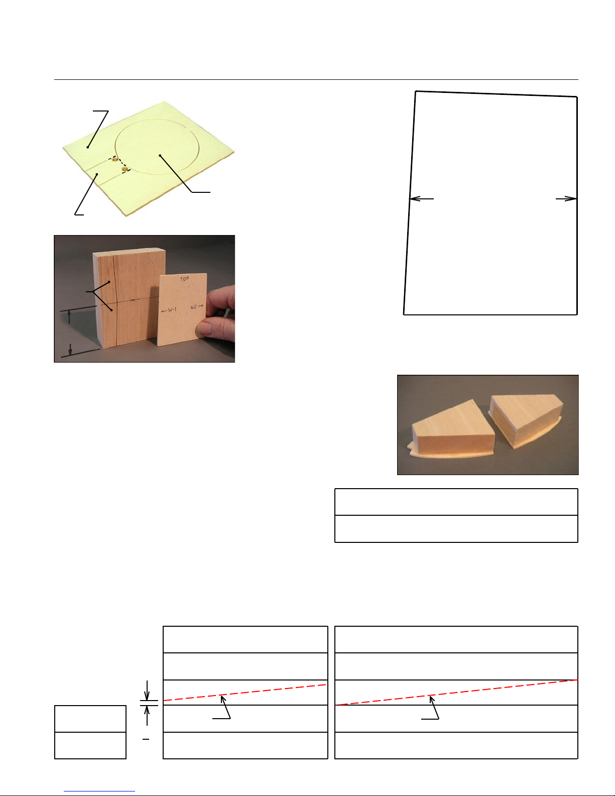
Wheel Well
Frame
Separate the lite-ply
wheel well floors from the wheel
TOP
well frames using a scroll saw or
hobby knife to cut at the dotted
LITE-PLY SHEAR WEB
lines shown in the photo at left.
Wheel
Well Floor
Scrap
The lite-ply shear web at
the wing root is also used as a
dihedral gauge during wing
W-1 W-2
construction. To avoid any
confusion, mark the shear web
as shown in the diagram.
Scrap
A 1" x 3" x 4" chunk of
balsa is provided as material for
87º
90º
the wing bolt support blocks.
2"
Use the shear web from the previous step as a template to mark the
proper shape of the support block as shown in the photo. Cut the block
into two pieces, and discard the scrap.
Glue the balsa dowel support blocks to the lite-ply dowel block
doublers. Line up the aft edges of each part.
Locate the six pieces of 3/32" x 3" x 36" balsa, then select the
two lightest, softest pieces to use as shear web material. The remaining
four pieces can be set aside to use as trailing edge sheets.
Inspect the 18 sheets of 3/32" x 4" x 36" balsa
supplied in your kit and select eight pieces to use for leading
Leading Edge Sheeting - Make 4 from
edge sheeting. Look for medium weight, long-grained sheets
that bend uniformly. Assemble four sets of LE sheets. Trim
3/32" x 4" x 36" Balsa - 2 Sheets, Edge Glued
the edges, then glue with yellow glue or thin CA.
The remaining ten sheets are used for center sheeting. Assemble two big sheets as shown below, then cut
them in half to make four center sheets. If you are going with open rib bays, cut the sheets first to a length of 23".
Finally, make two sets of wingtip sheets from 3/32" x 4" x 7-1/2" balsa. R54
Center Sheeting (Open Rib Bays)
Make 2 from 3/32" x 4" x 23" Balsa
Wingtip Sheets
Make 2
Cut Here
3"
4
Center Sheeting (Fully-Sheeted Wing)
Make 2 from 3/32" x 4" x 36" Balsa - 5 Sheets
Cut Here
NOTE: All Sheeting Diagrams are Not to Scale
Page 8
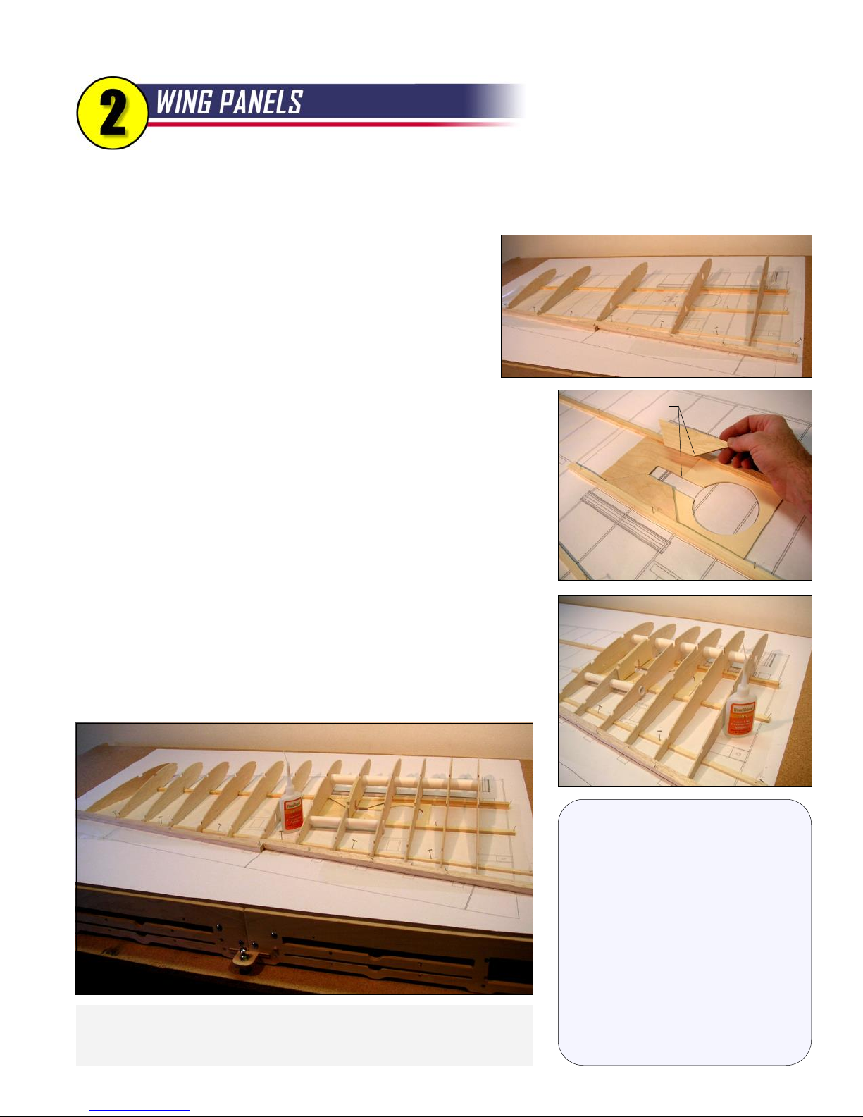
It cannot be stressed highly enough that a flat building board is essential to building a warp-free wing.
If you haven't done it lately, take the time to check your board with a long straight edge and make any
tweaks that may be needed to make it perfectly flat. It's time well spent!
Start by pinning the bottom main spar assembly to the
plan with the beveled edge facing forward. Use five ribs (W-2,W5, W-8, W-11, and W-13) as guides to position the bottom stub
spar (1/4" x 1/2" x 19-1/2" spruce), the bottom rear spar (3/16" x
3/8" x 36" balsa), and the trailing edge assembly. Don't worry if
you have any discrepancies with the plans - trust the parts! Pin
the spars and TE firmly in place, then remove the ribs.
Glue in the plywood retract mount and the lite-ply wheel well frame.
Align Corners
Add two plywood retract mount doublers. Make sure they are glued
well to the spars.
Glue in wing ribs W-2 through W-7. Use a triangle or the 90º corner
of the lite-ply shear web to make certain all of the ribs are perpendicular to
the building board. Note: You will save yourself trouble later if you keep
glue away from the area near the dihedral brace slots.
Install the servo lead tubes. The front tube is rolled from a full
sheet of 8-1/2" x 14" paper. For the rear tube, cut a piece of paper to
8-1/2" x 6-3/8". Use medium CA to glue the tubes to the ribs.
Glue in ribs W-8 through W-14.
About The Wing Design
like we have at my local club. That
requires a light wing loading, which
sport models in the past, which puts a
priority on building ease over pure
flight, the airfoil is close enough to
maneuvers as easily as inside.
Ribs W-2 through W-14 are now in place. I like to use thin CA during initial
construction when there is a tight fit between the parts. Later on, all of the
wood joints will be given a second coat using medium CA.
One of the design goals of the R54 was to
be able to fly into and out of a short field,
means lots of wing area! The airfoil is a
very unscientific shape I've used on many
aerodynamic efficiency. The flat portion
on the bottom helps keep things straight
and simplifies the retract installation. In
symmetrical that it flies through outside
7
Page 9
WING PANELS, continued...
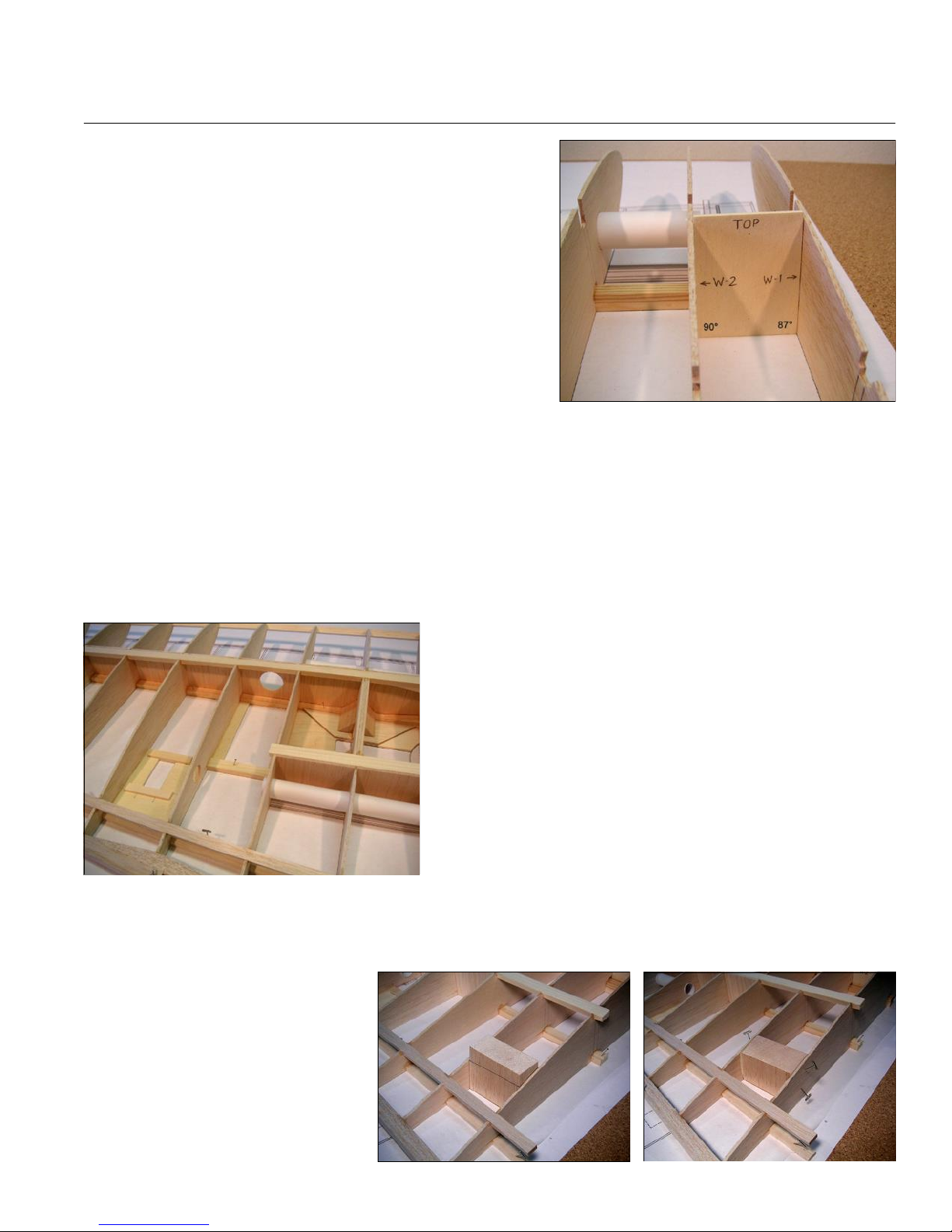
Glue in the root rib, W-1, this time using the 87º corner of
the shear web/dihedral gauge. Slide the dihedral gauge back and
forth as you glue to make sure the W-1 rib is angled properly along
its entire length.
Add the top main spar assembly, the top stub spar, and the
top rear spar to the ribs. Be sure to check the angle of W-1 to make
sure it hasn't shifted.
Glue the quarter-round balsa leading edge to all the ribs.
Once again, use the dihedral gauge to check W-1.
Go ahead and glue the lite-ply shear web/dihedral gauge in its place between W-1 and W-2. Thick CA works
well for this; apply it to the shear web where it will contact the spars and push it in place. Don't worry about gluing the
sides of the webs to the ribs right now; it will be easier to do later when the wing is lifted from the building board.
Add 3/32" balsa shear webs to the front spars (nine places) and the stub spars (four places). Remember, the
balsa grain must be vertical. One sheet of balsa should provide plenty of shear web material for one wing panel. I
suggest you trim the balsa sheet (selected earlier) to a width of 2-29/32", then slice off webs for the wider rib bays.
Once those are done, you can trim the remaining balsa to fit the narrower rib bays. Note: The shear web between
ribs W-7 and W-8 needs a 1-1/4" diameter hole to pass servo wires and air lines.
Locate the 3/4" balsa triangle material provided in the kit,
and cut four pieces 1-7/8" long. These braces are meant to
reinforce the joint between the W-6Ds and the retract mount
doublers. In a perfect world, the retract mount doublers would be
perfectly even with the spars, but in real life they are probably
slightly off. Take the time to notch the ends of the triangle braces
for a perfect fit, then glue them firmly in place.
Glue in the lite-ply hatch rail, the aileron servo mount, and
the flap servo mount. These items should all be pushed firmly
against the board so they are flush with the bottom of the ribs.
The balsa wing bolt block needs some final trimming before installation. Trial fit the block between W-1 and
W-2 (you will have to spread the top of the ribs apart so it will fit). Carefully mark the contour of the ribs on each end
of the block, remove the block, then draw lines on the front and back of the block connecting the lines on the side.
Now use a band saw, scroll saw, coping
saw, or razor saw to hack away the top
of the block, using the lines as a guide.
It is critical that this block bridges the
space between the top and bottom wing
skins to prevent crushing when the wing
is bolted to the fuselage. When you are
satisfied with the shape of the block,
glue it in place.
8
Page 10
WING PANELS, continued...
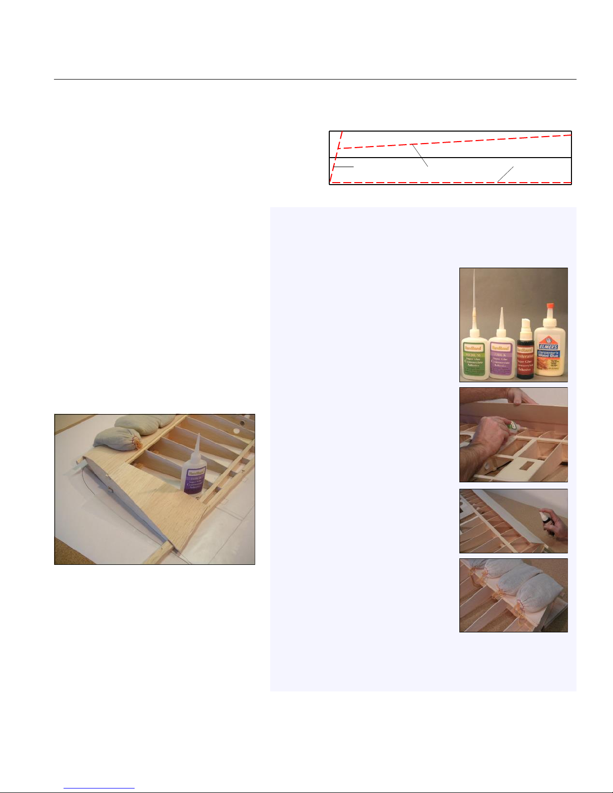
Select one of the leading edge sheets you assembled earlier, and trim it to fit. Start at the wingtip end, cutting
away a wedge that matches the angle of W-14. Now, hold the rear edge of the sheet flush with the rear edge of the
spar, mark the sheet at each end where it contacts the LE,
and make the cut using the marks as a guide. Finally, trim
the rear edge of the sheet so it will overlap halfway (1/4")
onto the main spar. Glue the LE sheeting in place and
allow to dry (see sidebar for details on a good method).
Optional: If you are building a fully-
sheeted wing, add a 3/32" x 3/8" capstrip to
the top of rib W-13.
Trim a piece of wingtip sheeting to fit
and glue it in place. Thick CA works well for
this step. You will need a tiny scrap of 3/32"
balsa to finish off the rear, inboard edge of
the sheeting.
Prepare a piece of 3/32" x 3" x 36"
balsa to be used for trailing edge sheeting by
roughly trimming it to shape, then glue it in
place. Use yellow glue on the tops of the ribs
and thick CA along the rear spar and TE.
The sheeting should overlap 1/4" onto the
rear spar, leaving about 1/8" of the spar
exposed.
Add 3/32" x 3/8" balsa capstrips to
ribs W-10, W-11, and W-12 (skip this step if
you are building a fully-sheeted wing).
Bruce's Method of Gluing on Leading Edge Sheeting
Adding LE sheeting to a wing is always a stressful step for me, probably
because I've botched it badly on previous models. The wood always seems
to be fighting me! Over the years I've settled on a method that works
pretty well and I'd like to share it with you.
1. Prepare your tools. I use yellow glue, thick
CA, medium CA with a long applicator, and CA
accelerator.
2. Prepare your sheeting. The sheeting needs to
be trimmed accurately along the front and rear
edge. The front edge needs to fit solidly with the
LE along its entire length.
3. Apply yellow glue to the top of the ribs. I like
yellow glue for this step because it dries slowly
and gives you time to perform the next step.
4. Push the sheet against the LE and apply
medium CA to the joint from underneath. This is
where the long spout helps.
5. Apply accelerator to the LE joint from above.
Avoid getting any spray on the spar, because you
don't want accelerator residue there when you
apply CA. The idea is to permanently glue the
sheet along the front edge so it can be lowered
onto the ribs with no worry of it popping up.
6. Apply thick CA to the spar where the sheet will
make contact.
7. Lower the sheet onto the ribs, and stroke it
from the LE towards the spar in an attempt to pull
it tight against the ribs.
8. Continue stroking the sheet until the thick CA
begins to grip. Press the sheet down against the
spar firmly, using accelerator if necessary.
9. Now the sheet is attached at the front and rear, but the yellow glue is still
drying. Use lots of weights like the shot-filled bean bags shown here to hold the
sheeting against the ribs while it dries. Be sure the wing is pinned down firmly so
the weights don't distort the structure.
Even though there is no photo, this is a critical step. Remove the wing from your building board and go over
every glue joint with medium CA. That means every joint on both sides, if possible. I like to use just enough glue so
you can see a small fillet formed between the parts. Use accelerator sparingly; it weakens the cured strength of CA.
First Cut Second Cut Final Cut
9
Page 11
WING PANELS, continued...
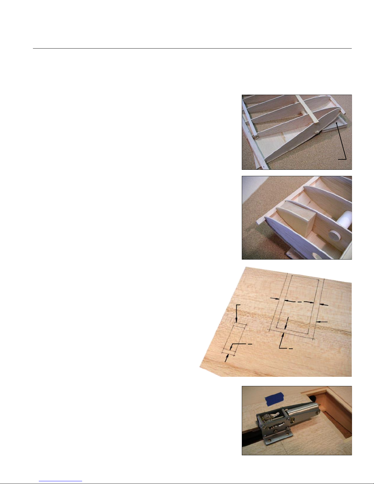
Block sand any irregularities off the bottom of the wing, then pin it upside-down to the building board. Pin it
firmly at the trailing edge so the TE sheeting is flat against the building board. The front portion of the wing needs to
be supported near the main spar. I suggest using two pieces of 1/4" balsa sheet (provided in the kit). Stack the
sheets then slide them rearward until they contact the balsa LE sheeting. The idea is to support the wing without
causing any twists or distortions. Pin the supports in place so they won't
shift around later.
Use thick CA to glue the wing dowel support assembly in place.
Add LE sheeting, wingtip sheeting, TE sheeting, and capstrips to
the bottom of the wing just as you did for the top of the wing.
Carefully trim the bottom center sheeting to fit snugly between the
LE and TE sheeting. Temporarily tape the center sheeting in place, then
remove the wing from the building board. Working from the top, mark the
outline of the hatch opening, the flap servo opening, and the aileron servo
opening. Also mark the retract mount area (don't worry about the wheel well
- you will cut it out later). Remove the center sheeting.
Let's start with the servo cutouts. The actual cutouts in the sheeting
need to extend an extra 1/4" at both the front and the back to make room for
the servo mounting flanges. Ultimately, the servos must sit on the lite-ply
mounts, not the balsa sheeting. Draw the extended outlines on the sheeting,
then neatly make the cutouts.
The wing hatch is actually larger than the opening that's drawn on
the sheeting. Carefully draw a hatch outline that is 3/8" wider on each side
and 1/4" wider at the rear. The front edge of the hatch is the front edge of
the sheeting, so no cut is required there. Cut the hatch out carefully,
keeping in mind that the cutout is not scrap - it will be used later as the
hatch cover.
Cut the retract mount area away using the lines that are
on the sheeting. Place the sheeting back on the wing and use
an actual retract unit (or the paper template included with the
kit) to mark the cutout area for the mounting flanges. Position
the retract with the mounting holes equally spaced on either
side of W-6. Remove the sheeting, then make the cutouts so
that there will be about 1/32" clearance all around the mounting
flanges.
Trial fit the center sheeting one last time, and mark the wing
structure through the cutouts you just made. The marked areas will indicate
"no-glue" zones. Remove the sheeting, then apply yellow glue to the wing
structure, being careful to avoid the no-glue zones. Put the sheeting in
place, then weight down the wing on your building board (use wax paper!)
right-side up so that the center sheeting is flat against the board. R54
Cut
Here
1"
4
Wing Bottom Center Sheeting
1/4” Sheets
for Support
3"
8
Cut
Here
1"
4
10
Page 12
11
At this point, the primary structures of the wing panels are complete. The last major part, the top center
sheeting, will be added after the wing panels are joined (this allows easy access to the dihedral braces so
you can be certain they are glued properly). This section wraps up some of the detail work on the wing
panels that is easier to do before the panels are joined.
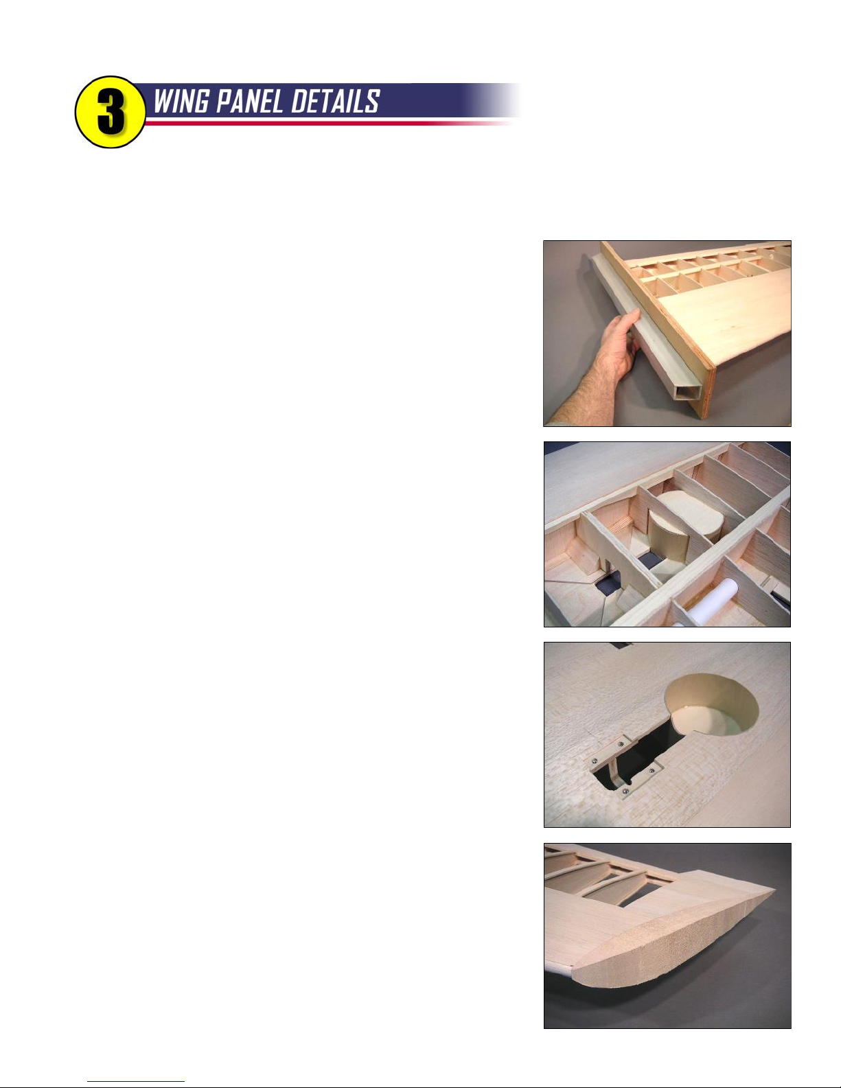
Trim the wing sheeting and spars at each end of the wing panel,
flush with ribs W-1 and W-14. It's critical to sand the root end accurately
so the panels will make firm contact with each other when joined. I made
myself an oversized sanding block just for this purpose using scrap
plywood, an aluminum bar, and a cut up sanding belt.
Trim the TE sheeting flush with the trailing edge. Maintain the
bevel in the inboard section of the wing panel.
Now you can finally cut the wheel opening and the wheel wells
away from W-4 and W-5 along the vertical lines you drew earlier.
Dry assemble the 1/32" plywood wheel well liner and the lite-ply
wheel well floor in the wing. The liner can be overlapped in the area cutout
for the strut, or you can trim the liner for a butt joint - your choice. When
satisfied with the fit and position of the parts, glue everything in place with
medium CA.
Use a sanding drum in a Dremel tool to make a rounded notch in
the liner to clear the wheel strut. Make a smaller notch in the retract mount
to clear the brass nipple on the side of the Robart retract unit.
Accurately place your retract unit in the wing and mark the position
of the mounting holes on the plywood mount. Remove the unit, then drill
the holes carefully for blind nuts. Install the retract mounting blind nuts and
fix them in place with medium CA. Note 1: Hardware for retract mounting
is not provided in the R54 kit, but it IS provided in the optional Retract
Package available from BTE. Note 2: If you do not have your retract units
at this time, you can still do this step using the Robart Bolt Pattern
Template provided in the kit.
Glue the wingtip trailing edge extension to the wing, using the
plans as a guide for proper placement. When dry, trim the end to match
the angle of rib W-14.
The balsa wingtip block is roughly cut to match the wing top view.
Mark the airfoil shape on the block using the actual wing as a pattern, then
saw the block to a rough airfoil shape. Glue the wingtip block in place with
yellow glue using pins and tape to hold it in position until dry.
Page 13
WING PANEL DETAILS, continued...
12
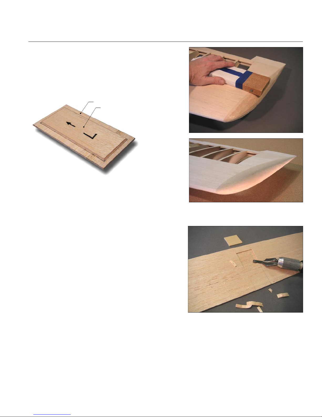
Carve and sand the wingtip to a pleasing round shape.
You can protect the surrounding sheeting by masking off a portion
of your sanding block with paper and tape.
The wing hatches that you cut out earlier need to be
stiffened with a balsa doubler. Use some scrap 3/32" balsa cut
Wing Hatch
Balsa Doubler
slightly smaller
than the hatch
opening which is
already drawn on
the hatch. Make
sure the grain of
the doubler runs
fore and aft,
perpendicular to
Use Six #2 x 3/8”
Sheet Metal Screws to
Mount the Hatch to the Wing
the hatch grain.
Glue the doubler
to the hatch.
Lightly sand the edges of the hatch, just enough to provide
some clearance for covering material. Mark the positions of the six
mounting holes, tape the hatch to the wing, then drill at the marks with a 1/16" drill bit. Remove the hatch and re-drill
the holes in the hatch with a 3/32" drill bit. You can toughen the wood around the holes in the hatch by applying thin
CA. Finally, mark the hatch to indicate the correct wing panel and
an arrow pointing forward to help with orientation later.
Mark the position of the wing bolt block on the bottom of
the wing by poking a few pin holes through the bottom center
sheeting. You will need to know the block's position later when
the wing bolt plate is installed.
Glue the root TE extensions to the wing, again using the
plans as a guide. Fill in the gap on the bottom of the wing with
scrap balsa sanded to fit. When dry, trim the inboard end flush
with W-1.
Cut a flap from the material provided in the kit. Sand the ends square, leaving about a 1/16" gap at each end
for clearance. Inset a 1/16" plywood control horn pad into the bottom of the flap, positioned as shown on the plans.
Cut an aileron and install its control horn pad just as you did for the flap.
Now is a good time to drill the flaps and ailerons for their control horns. The flaps use short horns (one left-
hand, one right-hand), and the ailerons use the long horns. Position the horns carefully, mark the mounting holes,
then drill at the marks with a 3/32" drill bit. I like to use a drill press for accuracy; prop up the surface so the ply pad is
perpendicular to the drill. Harden the wood around the holes using thin CA. NOTE: The flap horns are positioned
back from the hinge point to minimize the vertical displacement of the pushrod at full flap deflection. R54
Page 14
13
Clear your bench! You need some room to maneuver when you join these big wing panels. The center
wing joint is obviously a critical part of the structure. Take your time and use plenty of epoxy.
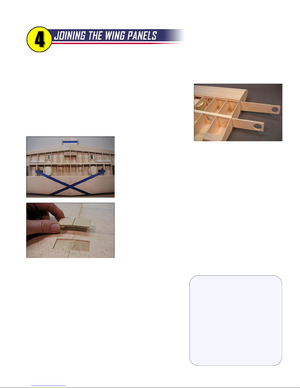
Cut away the slots for the dihedral braces in ribs W-1, W-2, and W-3. Make a rough cut with an X-Acto knife and
smooth up the edges of the slots with a thin sanding stick.
Trial fit the dihedral braces in each wing panel. You will need to sand
the bottom edge of the front brace and both the top and bottom edges of the
rear brace to match the angles of the spars. You want the braces to fit
snugly, but not so tight you have to force them in. Dry assemble the wing
and make sure everything aligns as it should.
Ah, the moment of truth!
Join the wing panels using a big batch of slow-dry epoxy. I like to use 3-hr.
epoxy, which normally gives a working time of 45 minutes or so. Coat the
edges of the braces, the spars and shear webs in the wing, and the W-1
ribs. Before the glue dries, pin the LE and TE to maintain alignment.
Stretch masking tape tightly from wheel well to wheel well to help pull the
wing panels together. Wipe away any excess epoxy with a rag soaked
with alcohol. Set the wing aside to dry thoroughly.
Inspect the braces and your glue joints carefully. If necessary, mix up
another batch of epoxy and re-glue any dry spots or gaps.
Trim the top center sheets for each wing panel and glue them in place
with yellow glue. I suggest doing one side at a time, using weights to hold
the panel down on your flat building board until dry.
Inlay the 3/32" plywood wing bolt plate in the bottom of the wing.
Using the pinholes you made earlier as a guide, center the plate on the
wing bolt blocks and trim away the sheeting to fit the plywood. Score the center of the plate with a sharp knife and
crack it gently until it matches the dihedral angle, then glue it in place.
If you haven't done so already, now is a good time to give the entire
wing a good sanding. You want to avoid sanding the sheeting as much
as possible (to avoid the "starved dog" look). However, there are areas
that will need attention like the joints between the center sheeting and
the LE and TE sheeting.
Fiberglass tape is provided in the kit to reinforce the center wing
joint. I use a light mist of 3M 77 Spray Adhesive on the tape to hold it in
place on the wing, followed by a coating of slow-dry epoxy. The epoxy
should soak through the glass and bond with the wood. Scrape away
excess epoxy and use an alcohol-soaked rag to wipe up any messes
About the Dihedral Angle
For the technical-minded amongst you,
the R54 was designed with three degrees
of dihedral measured on the bottom of
the wing. The usual method of laying
one panel flat and measuring the height
of the opposite wingtip above the table is
not really necessary with this model. To
my way of thinking, the precision of the
angle is not as important as making sure
there is a gap-free center wing joint. It
would be pretty difficult to be off more
than a fraction of a degree with the two
large dihedral braces setting the angle.
before the epoxy dries. R54
Page 15
14
The tail feathers are simple, all-sheet surfaces that build fast and easy. You can build these parts any
time during construction. They will come in handy during fuselage construction when you are routing
the pushrods, so let's get them done now and set them aside for later.
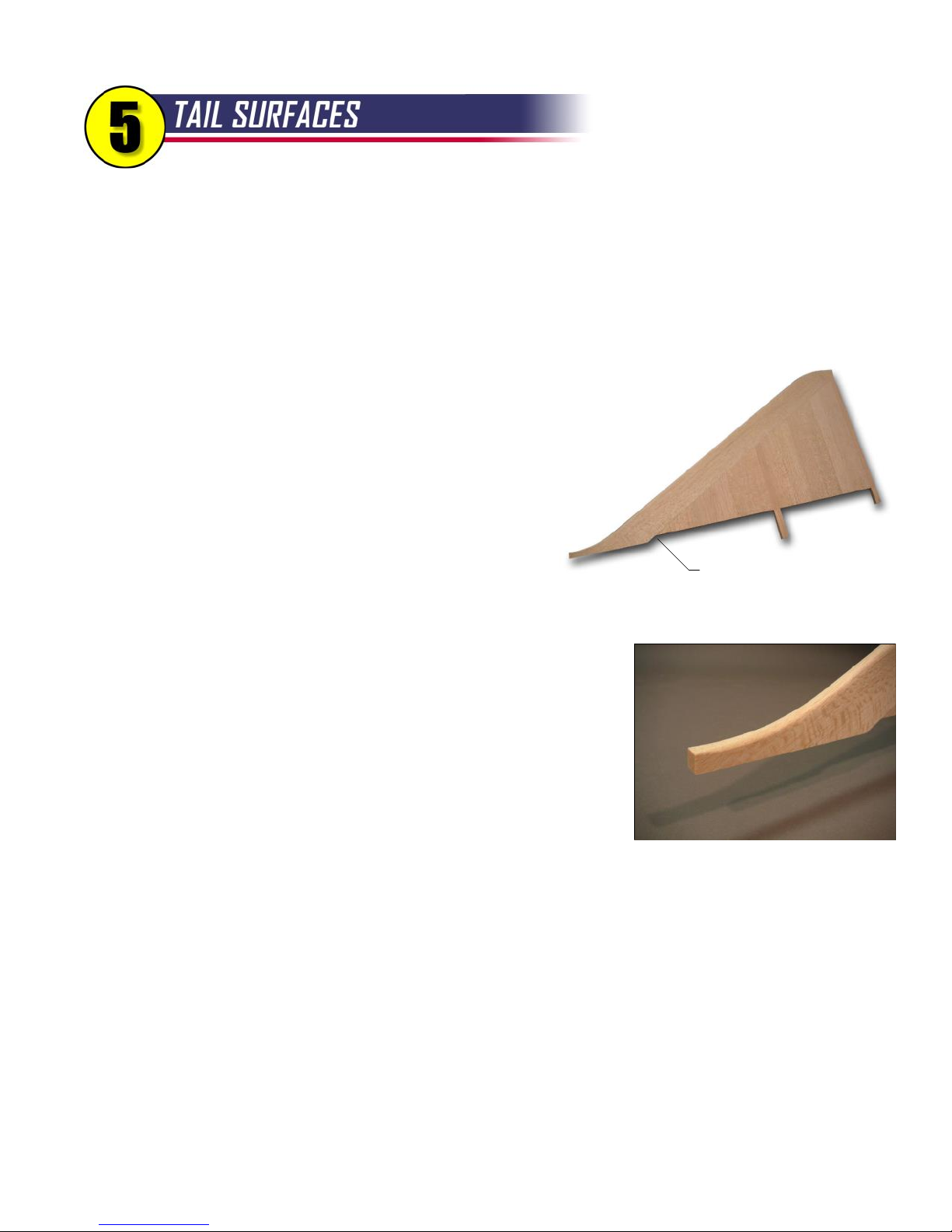
Let's start with the vertical stabilizer (fin). I recommend yellow glue (aliphatic resin) for all of the sheet balsa tail
surfaces because it's easier to sand smooth. CA tends to leave hard ridges at the glue joints that are difficult to make
"invisible". Pin and glue the FIN-1, FIN-2, and FIN-3 parts over the plan, being careful to align the bottom edges.
Cut the front fin post from the 5/16" x 1/2" balsa stick provided
in the kit. You can leave the top end of the stick long; it will be
trimmed later. The bottom end of the stick should match the angle
Finished Vertical
Stabilizer
shown on the plan.
Now add the FIN-4, FIN-5, and FIN-6 pieces, again aligning
their bottom edges. Allow to dry
Remove the fin from the board and carefully sand the top edge
smooth and straight. Pin the fin over the drawing again and add the
Add Scrap
FIN-7 piece. You want the front/forward end of FIN-7 to match the
plans. When dry, remove the fin from the building board and trim the rear edge of FIN-7 flush with FIN-1.
Cut another stick for the rear fin post and glue it in place. When dry,
trim the top end flush with FIN-7. You will also need to add a tiny scrap of
balsa at the front point of FIN-6
Sand both sides of the fin smooth. I like to attack this with an 80-grit
sanding block until the glue joints are virtually smooth followed up with
150-grit. Using this process, you may sand off up to 1/32" from the
nominal wood thickness of 5/16", which is acceptable. Round off the fin
LE, but leave the front tip squared off as shown in the photo.
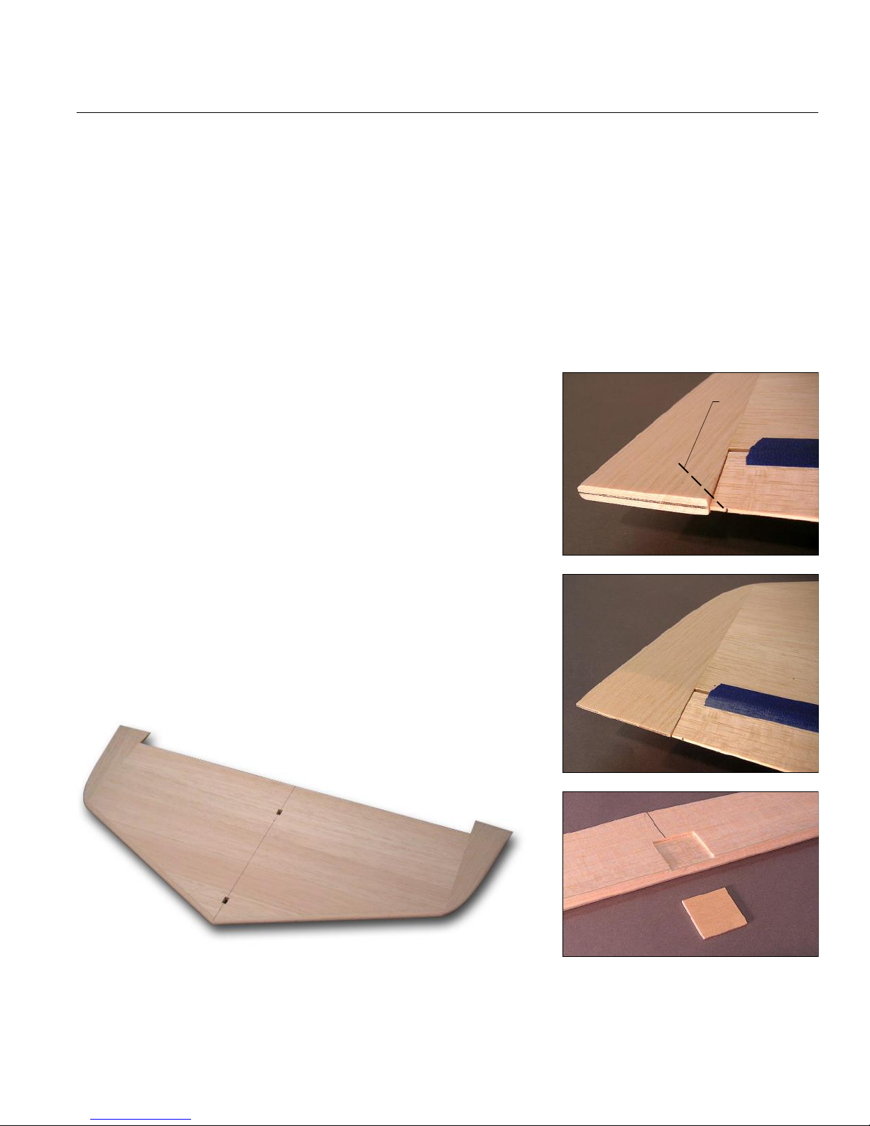
Cap both ends of the rudder with 5/16" sq. balsa. When dry, sand the caps to match the rudder contour. You will
notice that the TE thickness increases near the tip. It's okay to leave it that way, but purists (like me) will want an even
thickness along the entire TE. This is actually fairly easy to do using a few swipes of a sanding block. A carefully
drawn line, centered on the TE, will help guide your work and indicate that both sides have been sanded evenly.
NOTE: The actual thickness of the TE is not critical, but I do recommend that you leave it squared off, which is less
likely to flutter than a TE that is rounded off. The recommendation holds for all of the R54's control surfaces.
Temporarily tape the rudder to the fin, using the plans to accurately position the bottom edge of the rudder. Sand
the top of the rudder to match the contour of the fin.
Inlay a 1/16" ply control horn pad in the right side of the rudder using the plan as a guide. Do not install the
rudder control horn at this point - it will be installed later to align with the end of the pushrod.
Page 16
TAIL SURFACES, continued...
15
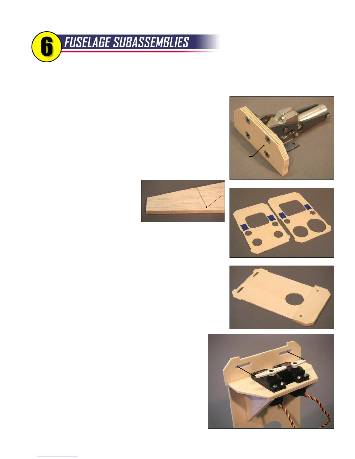
Now let's build the horizontal stabilizer (stab). Pin and glue the three STAB-3 pieces over the plan, followed by
the STAB-2 piece and the two STAB-1 pieces. Allow to dry.
Remove the stab from the board, and trim the corners off the most forward STAB-3 to match the angle of the stab
LE. Sand the LE smooth and straight, then add the 3/8" sq. balsa leading edge sticks. Trim the sticks for a tight joint
where they meet at the front tip of the stab. Allow to dry.
When dry, trim off the leading edge sticks at the tips and sand the outboard ends of the stab. Now you can glue
the two STAB-4 stabilizer tips in place.
Sand the top and bottom surface of the stabilizer smooth, and round off the leading edge and tips.
Sand the balsa elevator to an even TE thickness if you wish.
Trial fit the elevator to the stab, and sand the ends of the elevator
Insert Straight
Pin Here
(if necessary) for about 1/16" clearance at each end.
The STAB-4 tips need to be sanded to match the taper of the
elevator. Tape the elevator to the stab, keeping the ends of the tape
about an inch away from the tips. To really hold the elevator in position,
insert a straight pin at an angle through the elevator TE and into the
STAB-4 piece at each end. Now you can carve and sand the STAB-4
pieces to match the taper of the elevator.
Once again using the plans, draw an accurate centerline on the
top surface of the stabilizer (choose the smoothest side to be the top).
Carefully cut the two holes required for the fin posts. The holes should
be centered on the centerline that you just drew, and spaced to fit the
fin that you built earlier.
Inlay a 1/16" ply control horn pad in the bottom of the elevator. Use the plan as a guide - you will notice that the
pad is offset from the center line to better accommodate the control horn. Again, hold off on the actual installation of
the horn until later, when it can be aligned perfectly with the installed pushrod. R54
Finished Horizontal
Stabilizer
Page 17
16
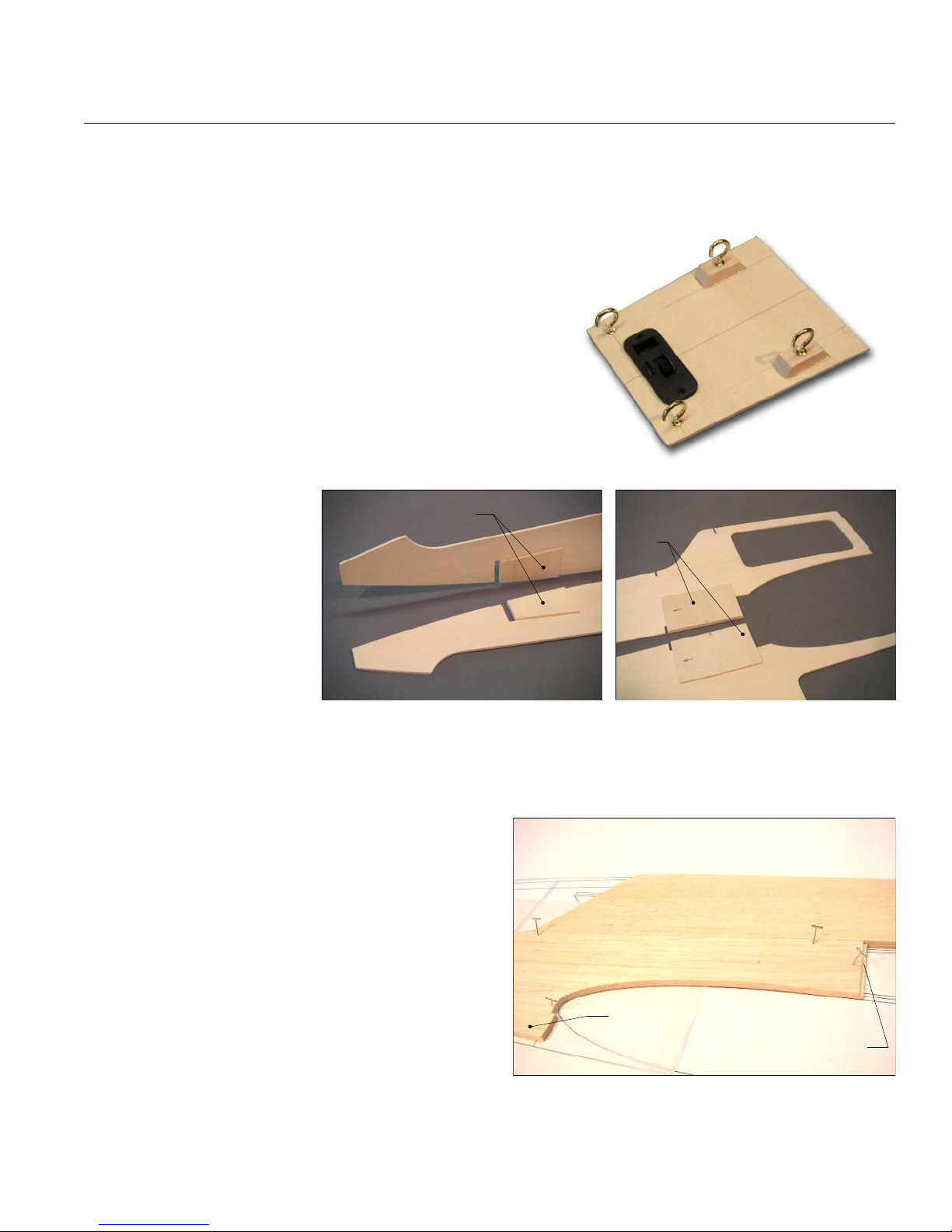
We're making progress! It will help if you have your servos and nose wheel retract on hand for some of
these subassemblies.
Find the coiled cable and nylon housing for the elevator and rudder
pushrods and cut them each into two pieces: 50" for the elevator and 48"
for the rudder. Lay the housings out straight somewhere out of the way,
and tape the ends so they can remain straight for a few days (or weeks).
Doing this will help relieve some of the curliness.
Add 4-40 blind nuts (included with the BTE retract package) to the
front of F-2 for the nose wheel retract unit. The retract should be centered
left-to-right and the top flanges should be in line with the top of F-2. Make
sure the beveled bottom edge of F-2 is facing the proper direction. Lock
F-2 Align Parts
Upside Down
As Shown
the blind nuts in place with CA.
Separate the SIDE-5 pieces from
the hatch sides using a scroll saw or a
SIDE-5
bandsaw to complete the cuts.
Cut apart F-3/H-3 and F-4/H-4 using the plans as a guide. Use a
knife, rather than a saw, to minimize the amount of material that is cut
Cut
Here
H-4
H-3
F-4
F-3
away. Tape the parts back together temporarily - they will be assembled
into the fuselage as a unit.
Prepare the F-5 bulkhead by adding two F-5D doublers. Drill through
the two wing dowel holes with a 1/4" drill bit. Connect the drilled holes at
the top of F-5 to make two slots for the control cables.
F-5
Glue the servo mount doubler to the bottom of the lite-ply servo
mount, then make a centered cutout for your elevator and rudder servos.
F-5D
(2)
The overall width of the cutout should be about 2-1/4", and the distance
from the front to the rear should match your servo length plus 1/16". Add
the two balsa braces to the bottom of the mount. Position your
servos spaced apart as shown on the plans, then mark the
mounting holes, drill, and mount your servos in place using the
hardware that came with your servos. NOTE: Some turbine flyers
Align Servo Arms
With Slots
F-5
omit the rubber servo grommets, thinking there's little vibration and
it removes a possible source of linkage slop. I went that route with
the first R54, but now think using the grommets is still a good idea.
With servo arms in place on the servos, glue the entire servo
mount assembly to the front of F-5. The servo arms must be
aligned vertically with the pushrod slots at the top of the bulkhead.
Remove the servos.
Page 18
FUSELAGE SUBASSEMBLIES, continued...
17
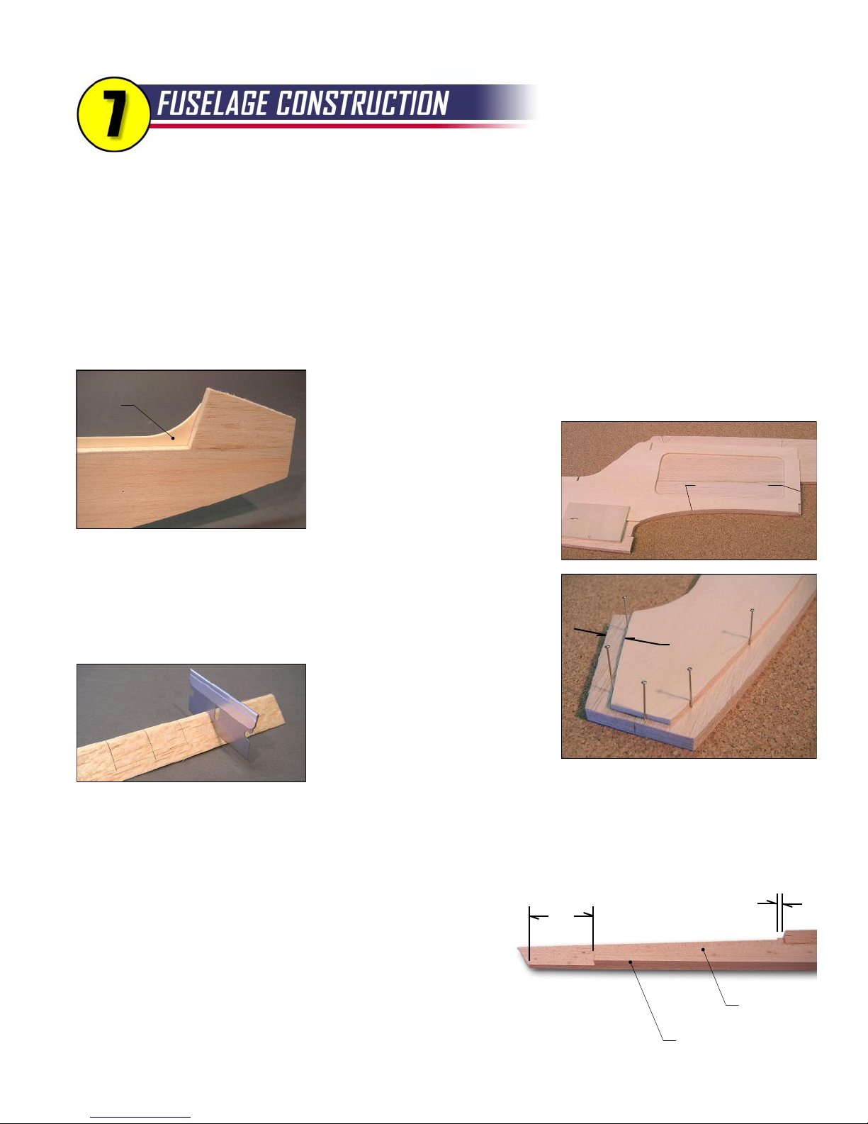
Cut the boat tail jig into two pieces, again using a knife. Tape the pieces back together. Eventually, the rear
piece will be glued permanently into the structure, and the front piece will be removed.
Prepare your lite-ply receiver shelf to suit your planned radio
installation, which may differ from what is shown here. I like to put
the cup hooks in place now, because clearance inside the fuselage
Receiver
Shelf
can be an issue if you wait until later. The front end of the shelf is a
handy place for the receiver switch, but it's up to you.
Glue the D-1 receiver shelf positioners to the lite-ply doublers.
CAUTION! Be sure to make a right-hand and a left-hand fuselage
doubler. It is critical to align the positioners with their bottom edges
flush with the bottom edge of the doubler.
Do the same for the D-2 ECU shelf positioner, but be careful!
D-2 is not a rectangle. Use
the plan to mark the bottom
edge and add an arrow
pointing forward on each D-2
D-1
D-2
to aid in positioning.
The fuselage plans are
printed in two pieces. Cut one
(or both) accurately along the
join line, then tape the two
pieces together. Use a long
straightedge to check some of the straight horizontal lines to be sure the plan sheets are aligned properly.
Build the two 1/4" balsa fuselage sides over the plans (protected with wax paper). Start by pinning down SIDE-1.
You may see slight discrepancies with the plan, but I suggest making sure it is positioned accurately along its rear
edge and the wing saddle. Add SIDE-2 through SIDE-5,
in that order, using yellow glue or thick CA.
Lay the fuselage side back on the plan and draw the
positions of the F-7 and F-8 bulkheads on the INSIDE of
SIDE-3
each fuselage side. NOTE: The notches on the SIDE-1
pieces will go on the OUTSIDE surface of the fuselage.
You should now have one left-hand and one right-hand
SIDE-1
fuselage side assembly.
R54
SIDE-2 Don't worry if
it's oversize - it will be
trimmed later
Watch
the Notch
Page 19
18
Now let's have some fun. The basic framework of the fuselage goes together fairly quickly. Pretty soon
you will be putting on the wing and taping on the tail and making jet noises in your workshop…
Trial fit the lite-ply fuselage doublers to the fuselage side. It is very important that both doublers are positioned
identically on their respective sides. You won't have any problems if you pay attention to these three critical areas:
- Aft Edge must align with aft edge of SIDE-1. Again, be careful to make a right and a left side.
- Wing Saddle must align with wing saddle curve of SIDE-1. It should line up perfectly except perhaps right at the LE.
- Top Nose Edge must be spaced 3/8" from top edge of SIDE-5. There should be about a 1/8" gap at the very front.
No Glue
Zone
Notice that the doubler actually extends about 1/4" above the balsa sides in the
hatch area, so you should tape the doubler in place, flip the assembly over,
and mark the "no glue" zone on the
doubler. For glue, I like to use thick
CA, but epoxy would work as well
(avoid yellow glue - it can cause
Align Here
curling on big surfaces like this). To
avoid having the doubler slip around,
arrange some straight pins as shown in the photo to act as guides for the
doubler as you lay it into place.
In the kit you will find two pieces of 1/2" balsa triangle stock with a
"nipped" edge. Apply this material to the fuselage sides with the nipped
edge resting against the doubler. You will need a long piece along the
bottom of the doubler and a short
piece along the top of the nose.
3/8"
If necessary, use a razor blade to
make partial cuts in the triangle
stock to make it easier to bend.
Apply a normal piece of triangle stock to the top of the fuselage sides.
The aft edge of the stick should end 1/4" forward of the little jog on the top edge of SIDE-4. Notice that the top of the
fuselage begins a gentle curve near the hatch cutout.
Finally, add a piece of 1/2" triangle to the top edge of each hatch side. At the risk of becoming annoying, be sure
to make a left and a right.
3"
1/4"
Add a 5/16" sq. balsa stick flush with the bottom edge of the
fuselage tail boom. The stick should start at the doubler and end 3"
forward of the bottom corner of SIDE-4.
Tape the hatch sides firmly in place on the fuselage sides - do
SIDE-4
not glue! I used blue masking tape so it would show up well in the photos.
5/16" SQ. BALSA
Page 20
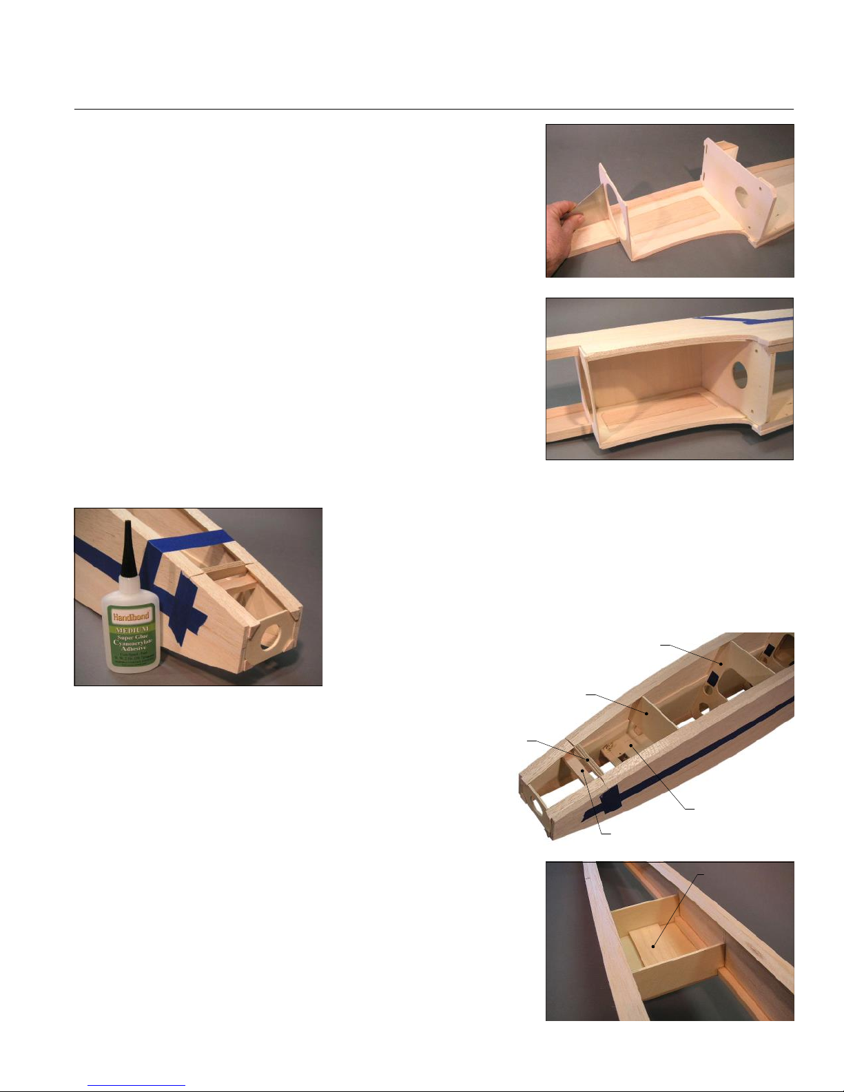
FUSELAGE CONSTRUCTION, continued...
19
Tack glue F-5 and F-6 to one of the fuselage sides, using a triangle to
make sure they are perpendicular. Now add the lite-ply fuel tank
compartment top (big rectangle) along with the opposite fuselage side.
Tack glue the parts, check the fuselage alignment over the plans, then glue
them all firmly. These parts will form a self-aligning box that is the core
section of the fuselage.
Dry assemble F-1 through F-4 in the nose of the fuselage, using tape
at the nose to hold everything together. You can check the overall
alignment over the plans, but it's difficult. This is where a trained eyeball
will come in handy. Stand a few feet in front of the nose and look for any
hint of twists or one side bending more than the other (the banana effect).
When you are satisfied that it's straight, start spot gluing the parts with
medium CA. CAUTION! Be very careful to keep the glue away from the
joints between the hatch sides and the fuselage sides.
Glue in the lite-ply receiver shelf and ECU shelf.
At this point there is a lot of bending pressure that might be fighting you, particularly near the nose. Apply tape or
temporary spreader sticks as necessary to hold things in their proper
position. Trial fit the 1/4" plywood H-1 to make sure it fits, then glue it in
place on the hatch.
Slide H-2 into position on the hatch. The final position is not critical,
you just want to slide it far enough forward that it causes the hatch sides to
bulge just a tiny bit
away from the lip of the
H-3
fuselage doubler. You
want just enough of a
H-2
gap to give the hatch a little wiggle room so it's easy to put in place
on the fuselage later on. Make sure the top edge of H-2 is even
with the top of the hatch sides and glue it in place.
H-1
Dry assemble F-7, F-8, and the 1/4" balsa stabilizer mount on
the aft end of the fuselage, again using tape and pins as necessary
to hold things in place. The fuselage top view on the plans is very
helpful for checking alignment during this step. When satisfied that
Temporary Balsa Spacer
Receiver Shelf
everything is positioned properly, glue with thin or medium CA.
Glue the 3/32" plywood turbine mount to the bottom of the tail boom.
Add the 3/16" plywood turbine mount doubler to the center of the turbine
F-8
Turbine Mount
Doubler
mount on the inside of the fuselage.
Sheet the bottom of the fuselage between F-6 and the turbine mount
F-7
with 3/32" balsa applied cross-grain.
Page 21
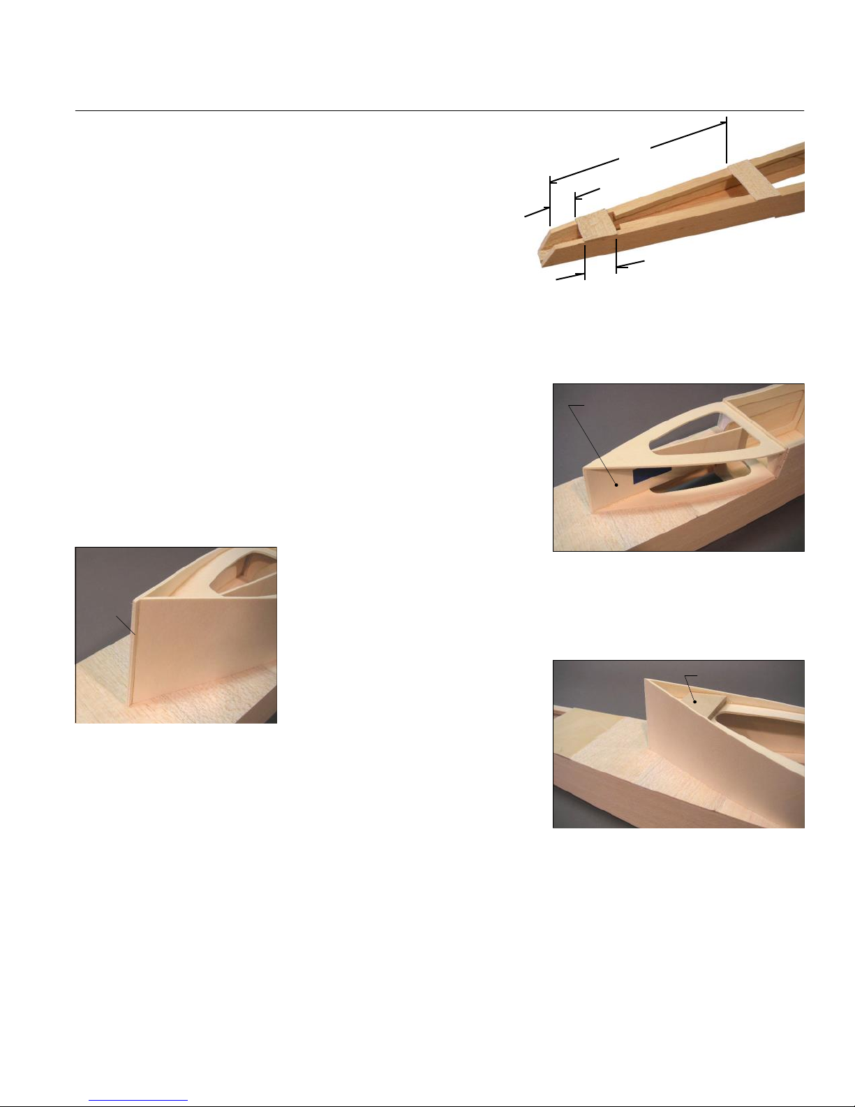
FUSELAGE CONSTRUCTION, continued...
20
Glue two pieces of 3/32" balsa sheet, 1-1/2" wide, to the bottom
of the fuselage as shown in the photo. These are the areas where the
two fin posts make contact. For now, it helps to leave the rest of the
10"
1¼"
fuselage bottom opened for access while installing the pushrods and
fin post braces. Sand all of the balsa sheeting flush with the fuselage
sides.
1½" - 2 places
Glue one of the boat tail formers to the sheeting, making sure the
point is centered side-to-side. Cut away the balsa sheeting to match the hole in the boat tail former.
Add the boat tail jig. Glue the aft end of the jig firmly, but just spot glue the front end on F-6. Make sure the jig is
centered and vertical. The jig is symmetrical, so it can be installed with either side pointing up.
Glue the second boat tail former in place. The front edge should be
Boat Tail Jig
parallel to the bottom edge of F-6.
Carefully sand the back edge of the boat tail jig to match the contour of
the formers and provide a wider gluing surface for the sides which are to be
added next. You can protect the balsa sheeting by putting masking tape on
the edge of your sanding block for this operation.
Now glue either one of the boat tail
sides in place. The front edge of the boat tail side sits in the notch in SIDE-1. The
rear edge of the boat tail side will have to be trimmed to match the angle of the
Trim
formers and jig. Glue on the second boat tail side, then trim its rear edge to form a
sharp point. The whole idea of the boat tail section is provide a smooth flow of air
to the turbine intake.
Wing Mount
Remove the tape on the boat tail jig
and break out the front portion.
Firmly glue the 3/8" plywood wing mount in the rear of the boat tail.
Use a sanding block to smooth the top edges of the fuselage in
preparation for the balsa sheeting.
Sheet the top of the hatch with 1/4" balsa sheet applied cross-grain. The sheeting must end right at the front and
rear corners of the hatch sides. Use yellow glue for this step because this glue joint will have to be sanded later. Hold
the sheeting in place with long strips of masking tape.
Glue 1/4" balsa sheeting to the top of the fuselage at the nose being careful to not glue it to the hatch sheeting.
When dry, remove all the tape from the sheeting and from the bulkheads inside the fuselage. You should now be
able to separate the nearly-complete hatch from the fuselage. Grab your bottle of medium CA and go over both sides
of every joint in the fuselage and hatch. R54
Page 22
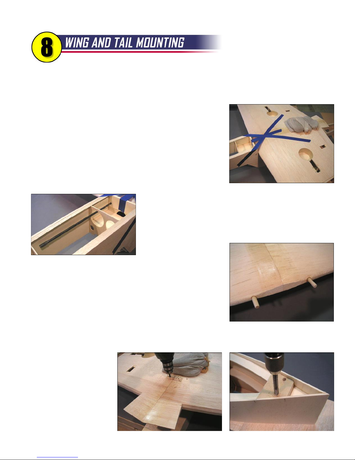
21
Time to put the big chunks together. Like any airplane, the alignment between the wing and the tail and
the fuselage is extremely important and ultimately affects the flight characteristics. Misalignments
become even more noticeable the faster an airplane flies, so it's particularly important with jet models.
Trim and sand the rear edge of SIDE-2 even with SIDE-1. You want the
balsa sides to extend about 1/16" aft of bulkhead F-5.
Sand off the LE point in the center of the wing to create a flat spot that
is four inches wide.
Trial fit the wing to the fuselage, paying close attention to the fit at the
leading edge. When satisfied, tape and pin the wing into its final position.
Measure carefully that the wing is centered on the fuselage and the distance
from the wingtip to the aft end of the fuselage is equal on both sides.
Drill 1/4" holes for the wing dowels into the wing through the holes in
F-5. This, I admit, is easier said than done. I ended up using a long drill
bit and twisting it by hand. A short piece of fuel tubing slipped over the end
gave a better grip. After drilling about an inch on each side, I removed the
wing and finished the holes with a power drill.
Epoxy the two 1/4" wing
dowels into the holes you just
made. Use plenty of glue, and leave about 3/4" of the dowels sticking out
from the LE. This is a little extra long, but it will help later when you are
assembling the model at the field.
When dry, put the wing back into position. The dowels will be pretty
tight right now, but they will eventually conform to the holes and become
pleasantly snug after putting the wing on a few times. Double check that
the wing position is accurate, then tape and pin it firmly in place.
The holes for the wing bolts should be centered fore and aft on the wing bolt plates and spaced 5/8" from the
wing center on each side. Mark the holes accurately, then drill all the way through the wing and the plywood wing
mount with a 3/16" drill bit. Do
your best to keep the drill
...Tap
perpendicular to the wing so that
the heads of the wing bolts will
sit flush on the wing bolt plate.
Drill and...
Tap the wing mount with a
1/4-20 tap, and harden the
threads with thin CA.
Page 23
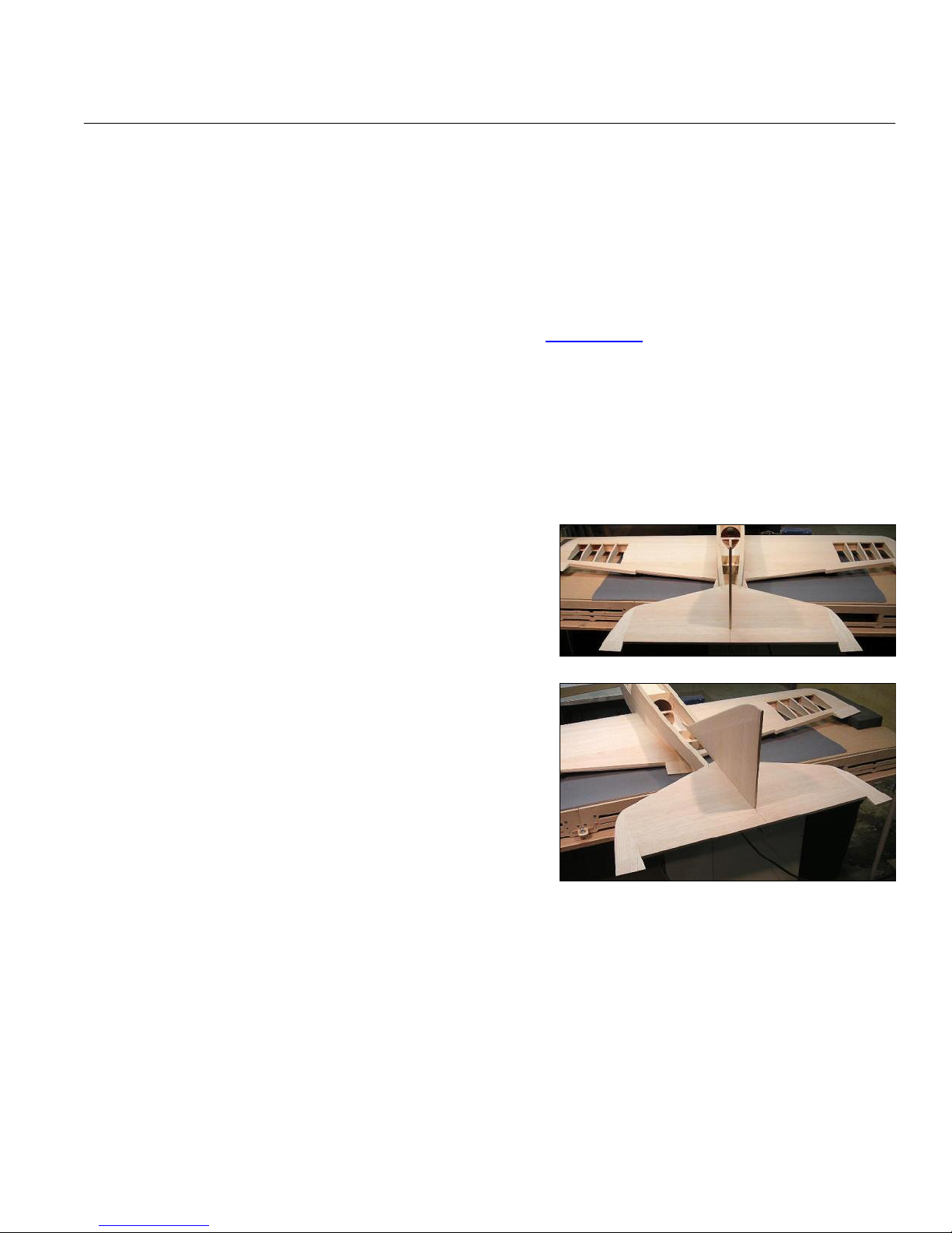
WING AND TAIL MOUNTING, continued...
22
Re-drill the holes in the wing with a 1/4" drill bit. Aluminum 1/4-20 x 3" screws and nylon washers are provided in
the kit for the wing bolts. The aluminum screws can be shortened to 2-1/2" if you wish, but be careful to keep the
threads intact.
OPTIONAL: The edges of the boat tail are fairly narrow and may cause dents in the top surface of the wing
when it is tightened down. You can add some balsa on the inside of the boat tail to provide more surface area if you
wish. You can make a perfect wing/fuselage joint by wrapping the wing in saran wrap, coating the wing saddle area
with an epoxy filler, then bolting the wing in place. The filler will ooze out on each side, but can be sanded away easily
when dry. I like to use Stits SuperFil epoxy for this operation. Visit www.stits.com for more info.
Position the horizontal stabilizer on the stabilizer mount. The front of the stab should align with the stab mount.
Measure carefully to make sure the stab is centered and that the distance from the stab tip to the wingtip is equal on
both sides. Also, stand back about ten feet and look directly at the rear of the model. If the stab is tilted in relation to
the wing, you may need to lightly sand one side of the stabilizer mount. When satisfied, pin the stab in place.
Mark the stab mount through the two holes in the stab, remove the stab, and cut the holes in the stab mount.
Glue the hardwood pushrod housing clamp to the rear-most
strip of balsa sheeting on the bottom of the fuselage. The groove
should be facing down, and should also be aligned with the centerline of the model. A drill bit placed in the groove temporarily will
help with visual alignment. This hardwood block is being glued in
now because it will form the base of the structure contacted by the
rear fin post when the fin is installed.
Replace the stabilizer, using the same pin holes that you used
originally, so you won't have to measure again. Trial fit the fin. The
two fin posts may need to be trimmed slightly to allow the fin to seat
firmly on the stabilizer. Use a triangle to be certain the fin is vertical,
then pin it firmly in place.
The bottom of each fin post is braced on either side with short
lengths of 5/16" sq. balsa. Cut four pieces, 3/4" long, and carefully
glue them to the fuselage (not the fin!). The front braces are glued
to the bottom balsa sheeting and the rear braces are glued to the hardwood pushrod housing clamp. The idea here is
to get the braces in place while you still have access through the fuselage bottom. You do not actually want to glue in
the fin right now, just the braces. Remove the fin and stab.
NOTE: The tail pieces have not been "officially" mounted yet, but they are ready. When the time comes later to glue
them to the fuselage, proper alignment should be quick and easy. The proper time to glue the tail surfaces to the
fuselage is up to you. I like to cover everything and then glue, but some modelers prefer to glue their tail on before
covering. Either way works - just be sure to use epoxy and pay careful attention to alignment. R54
Page 24
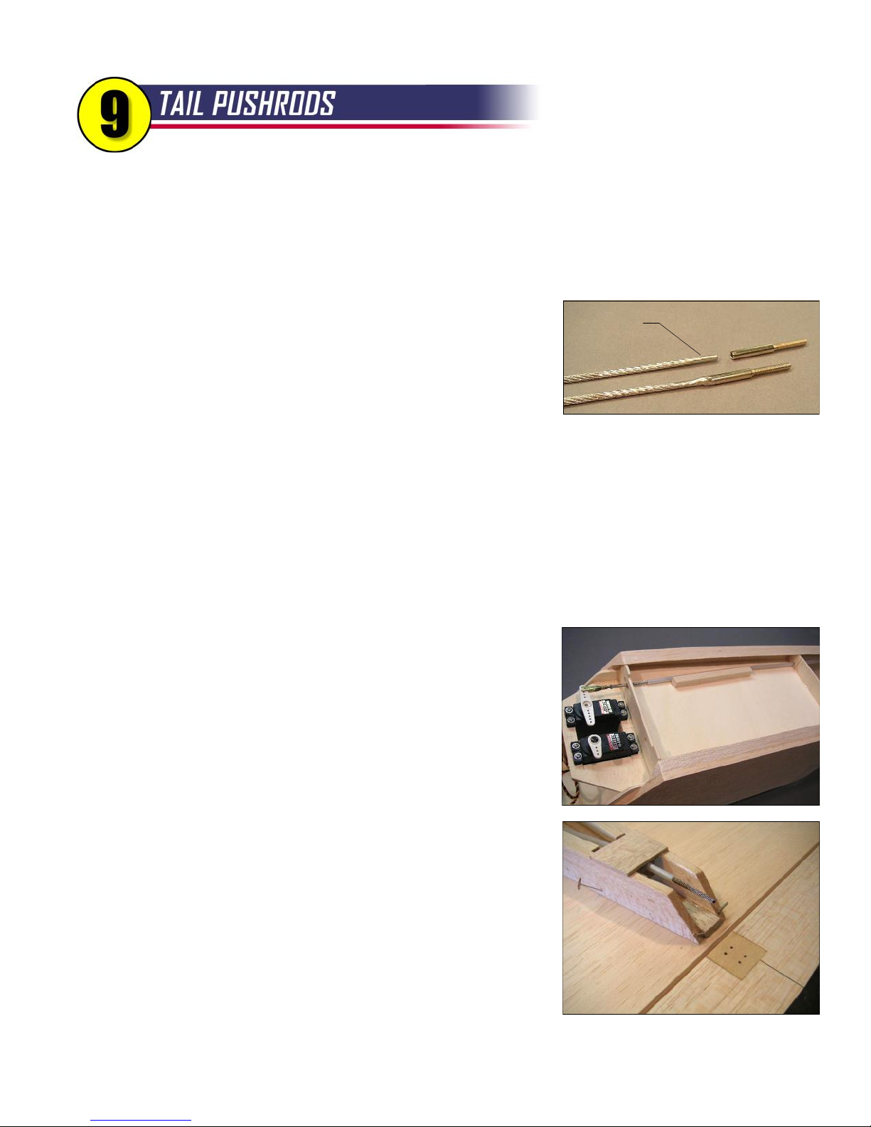
23
Technically, the linkages for the elevator and rudder in this design are push-pull cables, but for the sake
of simplicity, I will refer to them as pushrods. They do, after all, serve the same purpose as a rigid rod,
but their flexibility makes them easy to install. Make sure your elevator and rudder servos are in place.
Stiffen one end of each cable by flowing solder into the first two inches. Use good soldering techniques here:
clean the cable with alcohol, apply flux, then heat until the solder flows smoothly into the cable. Allow to cool, then
clean off the flux residue with dope thinner or lacquer thinner.
Grind
Solder a steel 4-40 threaded coupler onto each cable. You will have to
grind the soldered cable ends just slightly to make them fit into the couplers.
Heat the coupler and add more solder to the joint. When cool and clean, any
globs of solder hanging off the coupler should be ground or filed away.
Worried about the solder joint? After all, if the joint fails, your model will probably crash. I suggest you apply this
highly-scientific test. Put three or four hex nuts on the threaded coupler, clamp the nuts in a vice, grab the cable, and
give it a firm tug! If you can pull it out with your hands, you may have just saved your model. If not, you did a good job
of soldering and you can proceed without worry.
Now it's time to install the nylon housings (tubes), starting with the elevator. Before you put it in the model, swipe
the outside of the tube with sandpaper to roughen it up, then wipe it clean with alcohol. Make sure each end is cut
cleanly and the cable slides in without binding. Insert the 50" elevator cable into the 50" tube, then thread a 4-40 jam
nut and gold clevis onto the threaded coupler. Route the tube through the holes in F-5, F-6, and the hardwood clamp
at the tail. Connect the clevis to the elevator servo arm.
Cut a four-inch length of 5/16" square balsa to use as a guide for the
tube as shown on the plan. Notice that the end of the tube should be
positioned 3/4" behind F-5, and the end of the balsa stick is about an inch
back from the end of the tube. Get everything aligned, then glue the balsa
stick and the tube (medium CA works well) to the fuel compartment top.
Leave the front inch of the tube unglued so it is free to wiggle side-to-side
with the movement of the servo.
Now work your way back, gluing the tube to the fuselage side as you
go. It should pass right over the top corner of F-8. The idea is to route the
tubing as smoothly as possible back to the elevator. Glue it to the hardwood
clamp, but leave it free aft of the clamp.
Pin the stab to the fuselage, and tape your elevator in place. You can
now establish the final position of the elevator control horn. The long arm of
the horn should be very close to the model's centerline, but you can adjust
as necessary to make sure the cable flows smoothly to the control horn. You
can trim the tubing (remove the cable first) to its proper length, but I like to
leave the cable extra long until later. Mark the mounting holes for the control
horn, drill at the marks with a 3/32" drill bit, then harden the wood around the holes with thin CA. NOTE: The final
solder clevis will be installed after the model is finished and the stabilizer and elevator are in their final position.
Page 25
TAIL PUSHRODS, continued...
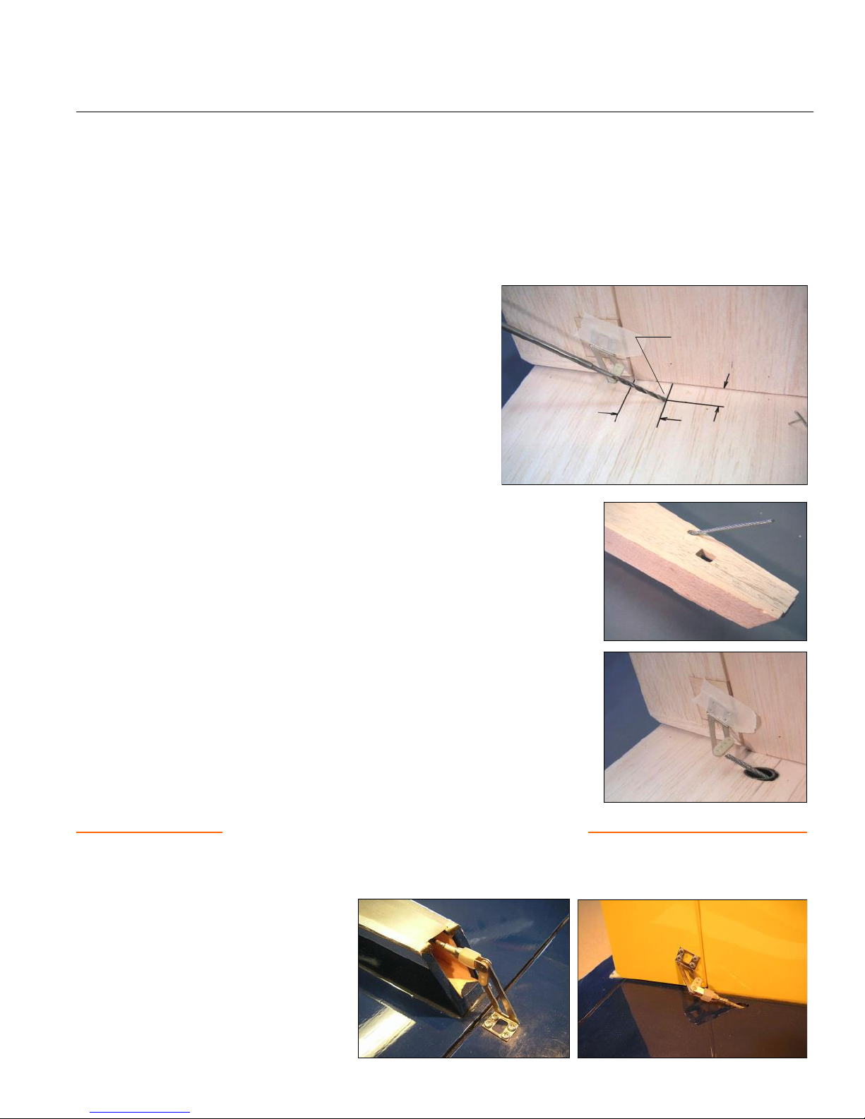
Add the fin to the top of the stab with the rudder taped in place. Temporarily tape the rudder control horn to the
rudder in the position shown on the plans (see Sheet 5). The angled orientation of the horn is required to match the
angle of the pushrod as it emerges from the stabilizer.
This might be the trickiest step in the whole building process. You need to drill a hole through the stabilizer and
stab mount at a low angle for the rudder pushrod. Use a long drill bit that is undersize, say 3/32". When viewed from
the side, the drill is obviously pointing down towards the stabilizer at an angle of about 30º. When viewed from the
top, the drill is also angled towards the center of the model.
Ideally, the drill bit needs to pass directly through the outermost
hole in the rudder control horn. It's nice to have the horn in
position for reference, but it's also in the way of the drill bit. Once
you have a good idea of the drill position, you can remove the
horn or swing it out of the way while you drill. The "magic spot" for
drilling through the stab is shown in the photo.
Ultimately, this hole must be enlarged to 3/16" to fit the
pushrod housing. You can use progressively larger drills, or work
more slowly with a small file. Remove the stabilizer.
Now you can route the rudder pushrod through the holes in F-5, F-6, and the
stabilizer mount hole. Again, route the tubing as smoothly as possible and glue it
to the fuselage as you did with the elevator tube. When you get to the aft end,
carefully glue the tube to the stab mount only (not the stabilizer). Cut off the
housing flush with the top of the stab mount.
The hole in the stabilizer needs to be enlarged to a diameter of 1/4" or more
to provide clearance for the cable and solder clevis. Use a drill, file, or Dremel tool
to enlarge the hole. Optional: You can leave the wood bare inside the hole, or
line it with some type of large tubing (not provided in kit - I used some black plastic
tubing about 5/16" diameter).
Finally, re-install the stab and fin, and use the installed pushrod to locate the
final position of the rudder control horn. Drill holes and harden the wood in the
rudder with thin CA.
Come back to this final step after control surfaces are hinged
Once the tail surfaces are glued in place and the control surfaces are hinged, you can add the final solder clevis
to the ends of pushrods. Start by cutting the cables to their final lengths. Remove the cables and stiffen the last 2"
with solder as you did at the front. Grind
the ends if necessary to fit the clevises.
Re-install the cables and carefully position
the solder clevises. The clevises must be
soldered in place on the model, so protect
the surrounding area with a rag while you
solder. Make final length adjustments at
the front end of each pushrod. R54
Magic Spot
1/2"
7/8"
24
Page 26
25
This section will more or less wrap up the construction of the wooden airframe. However, I strongly
suggest you look through the next four sections and think about how you plan on doing the installations
of your fuel system, turbine, retracts, and radio. It might be smarter to “glue a mount here” or “drill a
hole there” while you still have easy access to the fuselage tail boom and nose bottom. Once all the
sheeting is in place, you will only be able to work through the hatches and wing opening.
Spot glue the front hatch in place on the fuselage. Remember, you have to cut this hatch free after the fuselage
has been sanded, so just use a small drop of thick CA every three or four inches to hold it in place.
The main purpose of the rear hatch is to provide access to your safety fuel shutoff valve. The valve is typically a
ball-type Festo fitting provided with your turbine. Before each start you will open the valve and every time you shut
down the turbine you will close it, so it needs to be readily accessible. The actual position of the valve and hatch is not
written in stone - the plans show a convenient location, but it can be modified to suit your installation. The hatch itself
is simply a piece of 1/4" x 4" balsa. Later on you will add the tongue and rails, but for now cut a piece of balsa sheet to
serve as the hatch and spot glue it on the fuselage in a position that suits your particular valve installation.
Now that the hatches are in place, you can finish sheeting the rest of the fuselage top with 1/4" balsa applied
cross-grain. Leave a tiny gap between the sheeting and the hatches to allow some clearance after the covering is
applied. Two layers of masking tape works well as a spacer. The aft end of the sheeting will need to be carefully cut
to match the shape of the stabilizer LE.
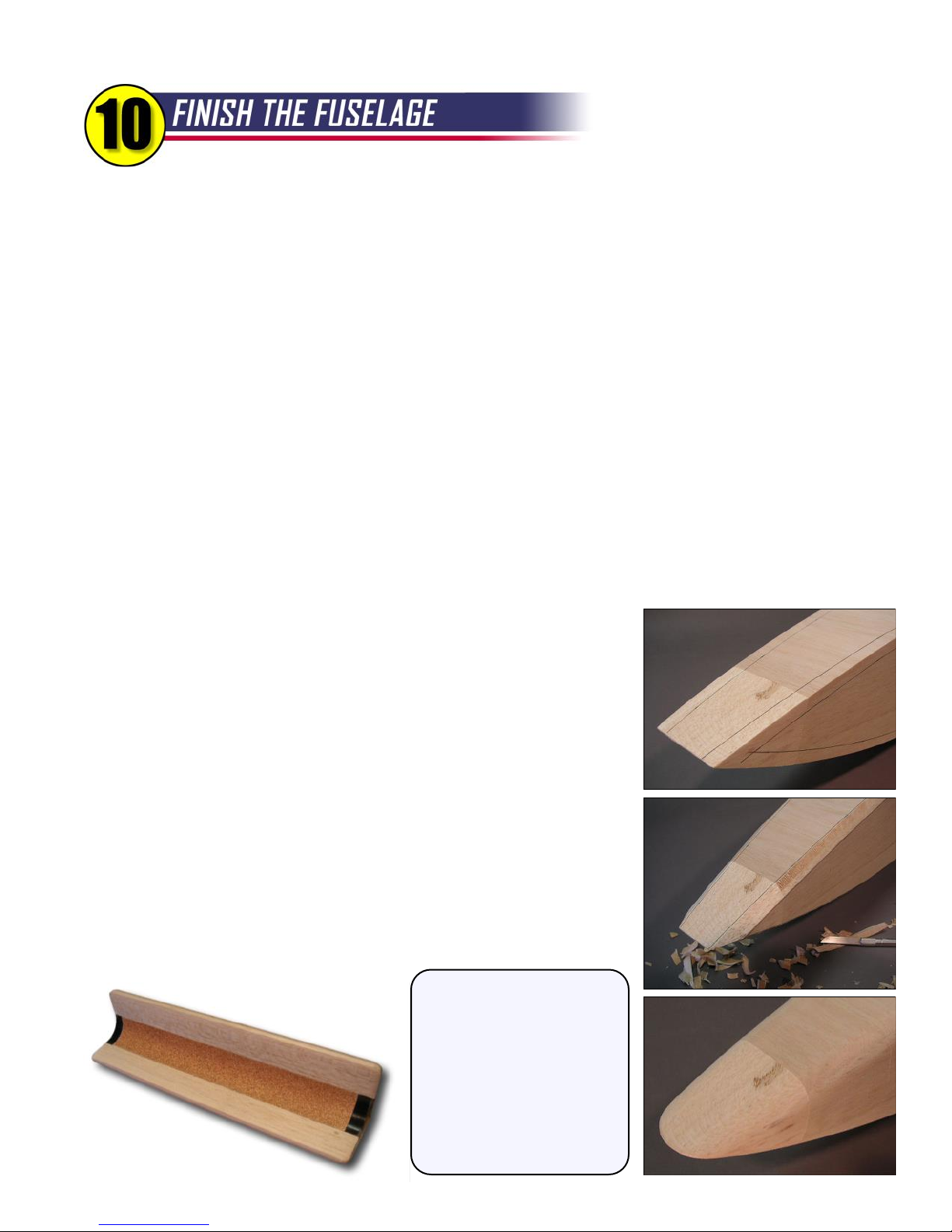
- Block sand sides squareBlock sand sides square
Sand the bottom of the fuselage from F-1 to F-5 with a sanding block to
-
- Draw lines 7/16" from cornersDraw lines 7/16" from corners
-
prepare this area for sheeting. You need to sand until you reach the surface
of the triangle stock. Apply 1/4" balsa sheeting, cross-grain, using yellow glue.
Finish sheeting the bottom of the tail boom with 3/32" balsa, cross-grain.
Sand the sheeting at the nose flush with F-1 to make a flat spot for the
balsa nose block, then glue it in place. NOTE: The nose block is not
symmetrical. The side that is nearly parallel to the balsa grain is the top.
- Carve corners close to linesCarve corners close to lines
-
Now it's time to make some balsa dust. Shape the fuselage corners as
detailed in the photos. Start with 80-grit and work your way up to 150-grit and
280- or 320-grit. You want the fuselage virtually ready to cover at this point,
because sanding after the hatches are removed may disrupt the smooth shape.
Corner Sanding Tool
Built
From Plywood,
Balsa, PVC Pipe, and
Some 80-grit Sandpaper
Corner Sanding Tool
I built the tool shown at the
left to help with the rough
sanding of the corners and to
maintain an even radius along
the entire length of the
fuselage. You can save
yourself some work and order
a fully-assembled sander from
BTE for only $14.95 .
- Round off corners with sanderRound off corners with sander
-
- Finish shaping nose by handFinish shaping nose by hand
-
Page 27
FINISH THE FUSELAGE, continued...
26
Rear
Hatch
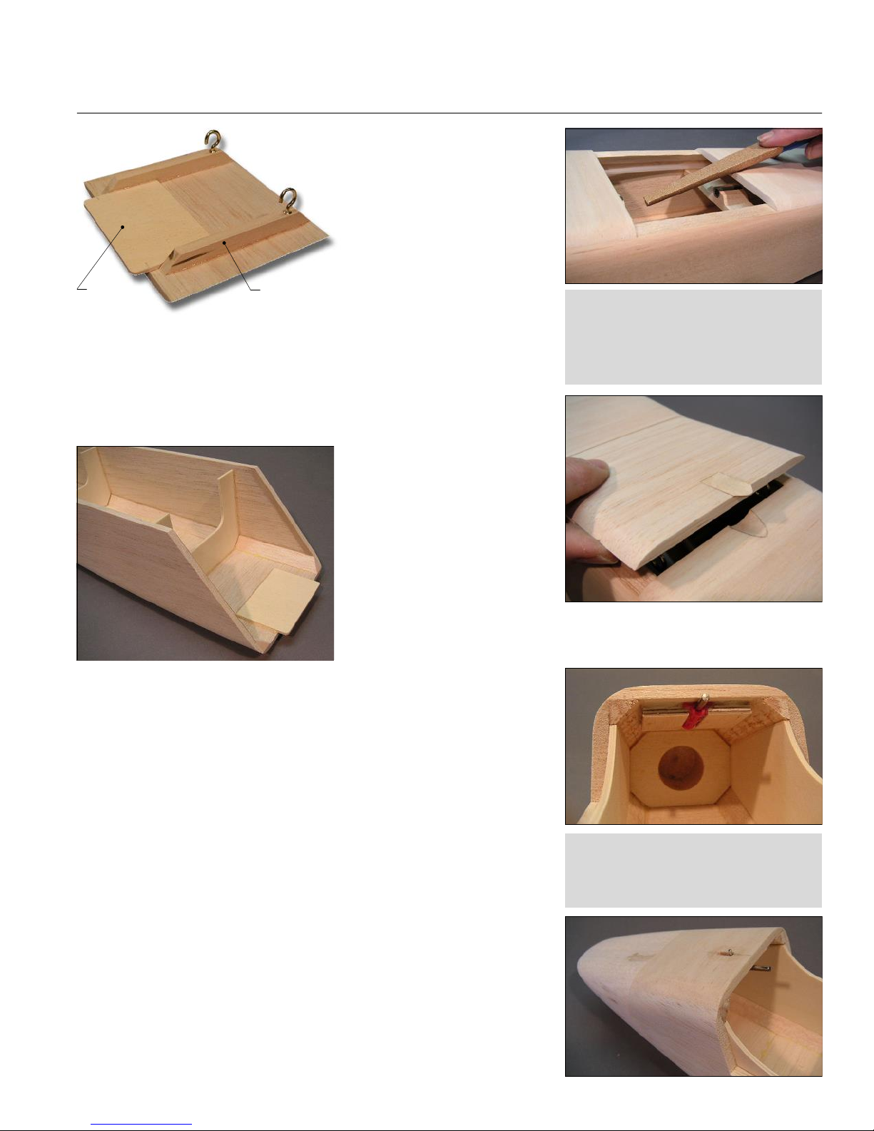
Carefully separate the
two hatches from the sanded
fuselage by cutting through
the glue spots with a razor
blade.
Glue a lite-ply hatch
Hatch
Tongue
1/4" x 3/8"
Basswood
tongue and two 1/4" x 3/8"
basswood rails to the rear
hatch as shown on the plans.
Add cup hooks to the rails and matching cup hooks inside the fuselage.
Also add two small scraps of wood under the top sheeting on either side
of the tongue to keep the hatch centered on the fuselage.
Finish off the rear hatch by imbedding the little 1/32" plywood tab.
Use a sanding drum in a
Dremel tool or a Fourmost
sanding stick to make a
corresponding, rounded notch
in the sheeting aft of the hatch.
Now let's work on the front
hatch. Glue the lite-ply tongue
to the rear of the hatch. In
flight, there will be a lot of lifting pressure on the big, curved hatch, so be
sure the tongue is glued very securely.
The front of the hatch is secured with a high-quality latch that is
included in the kit. You need to cut an accurate slot in the fuselage nose
sheeting for the latch, using the plans as a guide. Start by drilling two 1/8"
holes at each end of the slot, then connect the holes with careful knife cuts.
Harden around the slot with thin CA.
Wipe the metal latch housing with alcohol, then glue it under the top
nose sheeting with a small amount of epoxy. Make sure the lever is
centered in the slot and is free to move through its full travel. Also be sure
to keep the epoxy out of the mechanism! When dry, you can firmly lock the
latch in place using the two plywood hatch latch retainers. The small
grooves in the retainers fit over the latch flanges on each side.
The H-1 bulkhead at the front of the hatch must be accurately drilled to
engage the latch pin. To do this, start by applying a tiny dot of paint to the
very tip of the pin. While the paint is still wet, pull the latch pin forward,
position the hatch, and allow the pin to spring back so it makes a paint spot
on H-1. When you remove the hatch, you should have a nice round mark
showing exactly where to drill for the hatch latch. Carefully drill at the mark
with a 1/16" drill bit, then work your way up to a 1/8" drill bit.
The Fourmost Sanding Stick works great
for the notch. It is flat on one side and
round on the other, and is tapered along its
full length. Best of all, it's inexpensive and
available from BTE! See Appendix B.
Update: The plastic latch shown in these
photos has been replaced with a stronger
all-metal latch in later kits. Slot position
for the new latch is further forward.
Page 28
FINISH THE FUSELAGE, continued...
27
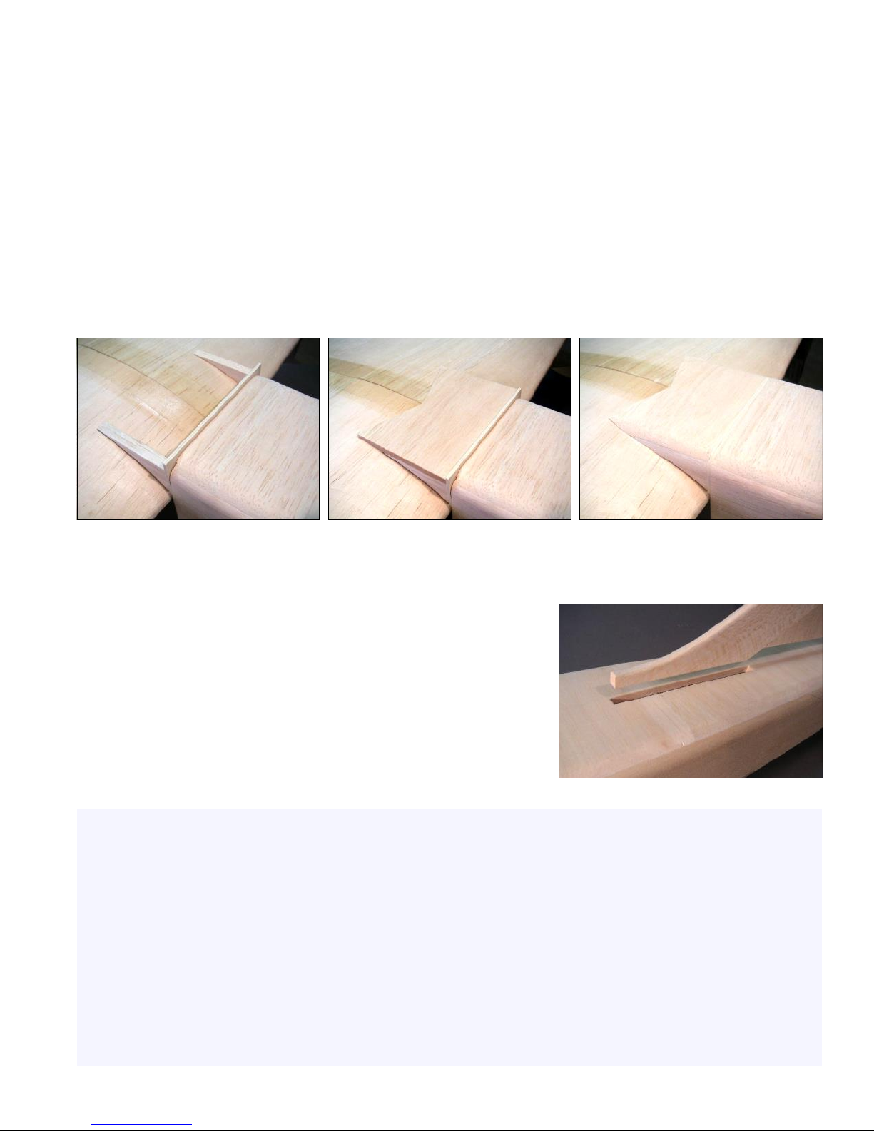
Okay, the fuselage fairing is actually a part of the wing, but it's like an extension of the fuselage, right? To be
honest, the fairing requires some tedious cutting and fitting and is not actually required from a structural standpoint.
For those reasons, I consider it optional, but the model wouldn't look right without it! Start by bolting the wing in place.
The fuselage fairing face plate is cut from the lite-ply rectangle supplied in the kit. You need to trim the long edge
where it contacts the wing to match the dihedral. Glue it to the wing, leaving a small gap for clearance (again, two
strips of tape works well as a spacer).
Use the supplied template to cut two fairing sides from the piece of 3/8" balsa included in the kit. Glue the fairing
sides to the wing and the face plate. The outer edges of the fairing sides should be in line with the fuselage sides.
Add 1/4" balsa to the top of the fairing sides. At the front, the balsa will seat against the fairing plate. At the rear,
you will need to trim and taper the sheeting carefully as shown in the center photo so it flows smoothly into the wing.
When dry, carefully shape the fairing to flow smoothly into the contour
of the fuselage. Apply masking tape to the wing to protect it during the
sanding process. Most likely, the fairing will require some filler around its
edges to finish it off properly.
Cut a slot in the fuselage top sheeting for the front of the fin. Make
sure the slot is centered on the fuselage and try for a snug fit. R54
Congratulations, your airframe is now complete!
Covering - I recommend using a high-quality plastic film covering like Monokote or Ultracoat. BTE offers full-size
templates for the color scheme used on the prototype if you wish to duplicate it. Plan your overlaps and seams so
they are all facing rearward to avoid any chance of lifting during flight. At the field, keep an eye on the open rib bays.
Any punctures or tears must be repaired before attempting another flight.
Easy Hinges - Easy Hinges are designed to be installed after covering. Cut accurate slots with a sharp knife, and
install all the hinges dry - no glue yet! Make sure the control surface is positioned exactly where you want it, deflect it
in both directions, then apply THIN CA to both sides of every hinge. You must use thin CA, the fresher the better, for
maximum penetration of the hinges and wood. I like to apply at least five big drops, but I watch the hinge carefully to
be sure it is still soaking the glue in. The first few drops will absorb quickly, then it will begin to slow down. I stop
when the last drop takes about five seconds to flow in. Do not over-glue, and do not apply a second layer. When
done properly, the hinges should actually appear dry.
Page 29
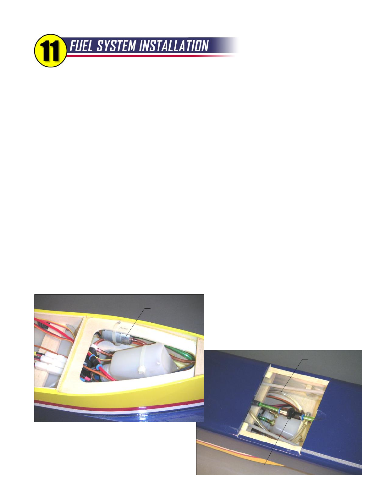
28
The remainder of this booklet is less like instructions and more like a show-and-tell. Even though you
may use a different turbine, radio, and accessories, you might find the descriptions here useful.
Fuel System Overview - The manual supplied with your turbine most likely contains info on the recommended fuel
system arrangement. Be sure to follow their recommendations for fuel line sizes and sequence of tanks, solenoids,
pump, and filter. For a jet, the Reaction 54 uses a very simple fuel system. The single main tank feeds a header tank
that feeds the fuel pump. The positions of the main tank and a UAT header tank are shown clearly on the plans. You
can position your other components as shown in these photos, or differently to suit your taste. BTE offers a Fuel
System Accessory Package that will come in handy for your installation (see Appendix B for more info).
Main Fuel Tank - Assemble the 60 oz. Du-Bro Tank included with your kit, being sure to use the kerosene-friendly
brown rubber stopper with the molded "0". The tank needs only two lines - one is the feed line (with the clunk) and the
other is the vent line. The kit also includes a soft foam pad that goes at the top of the fuel tank compartment. It
doesn't have to be glued in, but you can epoxy it in place if you wish. The foam isn't there to absorb vibration; it's
meant to compress when the tank is mounted with the two 1/4" x 1" balsa sticks as shown on the plans. The balsa
sticks are wedged above the cutouts in the fuselage doublers, and can be left unglued. A neoprene rubber pad is also
provided in the kit to provide a small cushion at the front of the tank. In the event of a crash, the neoprene pad might
just be the difference between a ruptured fuel tank or not. Use epoxy to glue the pad to the back of F-5.
About the Main Fuel Tank Orientation - The plans show the main tank with the stopper aft and the clunk forward.
I've never had any trouble with it that way, but some builders prefer to switch it around so the clunk is at the rear.
Either way works fine, so if it seems more natural to have the clunk aft, go ahead and install it that way.
Header Tank - The UAT is my header of choice for this model. With a UAT, the total fuel capacity of the Reaction 54
is 64 oz. There is plenty of room for a larger header tank if you wish, but keep in mind that extra fuel not only adds to
your flight time, it increases the overall takeoff weight.
Fuel Pump
A larger header tank will also require extra nose
weight if its position is kept behind the CG. Whatever
you choose for a header tank, make sure it is
mounted securely. There are three lines attached to
the header tank - the first one is connected to the
UAT
feed line from the main tank, the second one goes to
the shutoff valve and on to the fuel pump, and the third
is for filling. Keep the fill line plugged at all times
except for when you are actually fueling (or de-fueling)
the model.
Fill Line - Coil
When Not In Use
Fuel Shut-Off Valve
Page 30
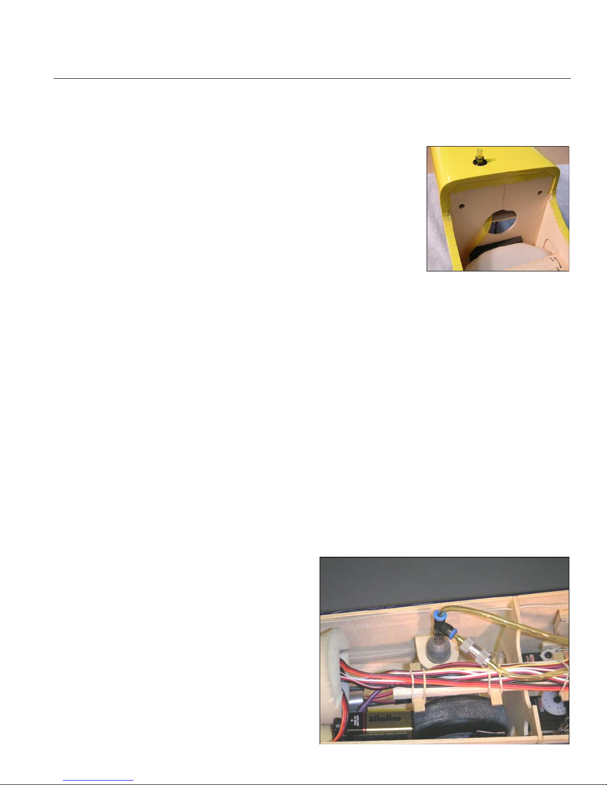
FUEL SYSTEM INSTALLATION, continued...
Fuel System Installation Tips and Notes
Use kerosene-compatible tubing for your vent line, such as Tygon. The vent line can be routed anywhere you
wish. My preference is to route it to the bottom of the fuselage ahead of the wing. Keep in mind that the vent line
also serves as the overflow line when fueling. Add a small O-ring to keep the
vent line from sliding up into the fuselage.
The vent line from the main fuel tank must always be open during fueling and
turbine operation. However, it's been my (unpleasant) experience that kerosene
will find a way to drip from the vent any time you put it in your vehicle, or even
when you turn the model over for assembly. For that reason, you should plug
the vent when you are transporting or doing maintenance. Add a red streamer
on the plug so it's more visible.
The fuel pump can be strapped to the boat tail former with a tie-wrap as shown
in the photo on the previous page. Fuel pumps are small electric motors and
have been known to create RF "noise" that can cause problems with your radio.
Make special efforts to keep the pump as far away as possible from any wiring, particularly your radio antenna.
One thing you do not want in a turbine model is fuel leaks. Take the time to secure every connection in your fuel
system, even the clunk line inside the main tank. I use safety lock wire, wrapped twice around the tubing then
twisted. Others like to use small tie wraps; two on each connection with the heads aligned 180º apart.
Festo fittings are commonly used in turbine models, and they work great when properly installed. To avoid air
leaks, be sure to cut the ends of the fuel tubing that will go into the Festo fitting clean and straight with a razor
blade. Also try to route your fuel line so that it is straight when it goes into the fitting. Festo fittings have been
known to leak when positioned where the fuel line is making a tight bend.
If your turbine uses external solenoids, they can be mounted to the model with tie wraps or Velcro. If you use
stick-on Velcro, be sure to apply a thin layer of epoxy or CA to the wood and allow it to dry before applying the
Velcro. It will stick much better to the dry glue than to bare wood.
To help extend flight time, jet modelers commonly use an overflow or "taxi" tank. This is a separate fuel tank
(typically 10 - 20 oz.), external to the model, that is hooked up to the main tank's vent line during startup. With
this arrangement, the main fuel tank remains full until the taxi tank is removed just before takeoff. Taxi tanks are
popular at jet fly-ins where you sometimes have to wait a considerable time for the runway to clear.
Installing the Gas System
In addition to the fuel system, some older-style turbines use a completely separate propane gas system for starting.
The turbine ignites and runs on the propane/butane gas for a few seconds before switching over to the kerosene fuel
system. The tank for the gas system is usually a small
metal canister that needs to be mounted vertically. The
photo shows my propane tank (looks like a C02 cartridge)
secured with a plywood bracket. It was mounted well
forward in an attempt to keep as much weight toward the
nose as possible. The plans show an alternative location
next to the ECU that would also work. The fill line on your
propane tank should be secured during flight by strapping
it under one of the rubber bands on your wiring rack.
Another option is to arrange an external system where the
propane is hooked up just for starting, then removed from
the model once the turbine is running. Again, check your
turbine instructions for details. R54
Vent Line
29
Page 31
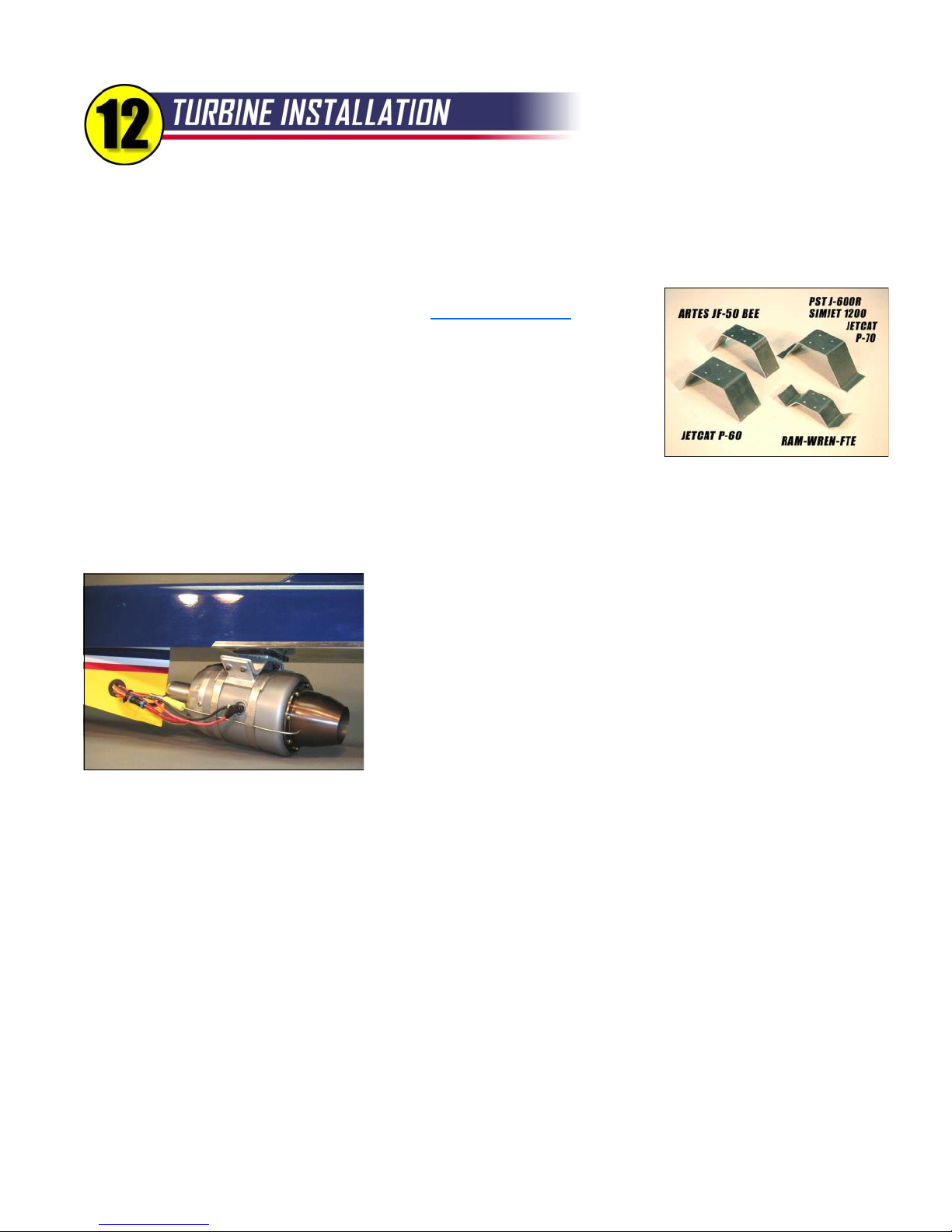
30
This will be a brief overview of the turbine installation on the Reaction 54. You really need to consult
the instructions that came with your turbine for detailed information on hooking up your turbine.
Turbine Mount - BTE offers several types of aluminum mounting brackets for this model. The RAM-style bracket is
the smallest and lightest, but requires a set of straps and tabs like the ones shown
in the photo below (straps and tabs available from DreamworksRC.com). The
PST-style bracket was designed specifically for the PST J600R turbine and the
mounting straps that are normally provided with that turbine. The PST-style
bracket also works with other turbines using spacers (provided by BTE). Also
available are brackets for the JetCat P60-SE and the Artes Super Bee. I can work
with builders to develop special mounts as needed. Give me a call and we can
work out the dimensions.
Thrust Angle - During flight testing of the R54, it became evident that a significant nose-up angle on the turbine
engine was needed to provide trim-free response to changes in throttle setting. The proper angle eventually worked
out to be 6-1/2 degrees in relation to the stabilizer/fuselage top. The kit includes a hardwood wedge that will set your
turbine mount at the proper thrust angle. For balance purposes, the turbine should be mounted as far forward as
possible. In fact, a neatly-done notch in the rear edge of the boat tail may
allow you to move the turbine forward an extra half inch or more. Use four
#6 x 1" stainless steel sheet metal screws to hold the aluminum mount and
thrust wedge in place.
Heat Shield - The hot exhaust stream from the turbine doesn't even come
close to the bottom of the fuselage or stabilizer. The turbine itself, however,
gets very hot and can radiate heat for some time after shutdown. For this
RAM 500
reason, the kit includes a thin sheet of stainless steel to protect the bottom
of the fuselage above where the turbine will be mounted. I suggest buying
an expendable pair of scissors to cut the material to the fuselage shape. Holes for the turbine mount screws can be
drilled or punched. Once it is epoxied in place, use the aluminum tape (cut into 3/8"-wide strips) to hide the edges.
Fuel Lines and Wiring - All of the wiring and fuel/propane lines going to the turbine need to be routed through a hole
in the side of the boat tail. The kit includes a rubber grommet to protect the wires and fuel lines from chafing. The
grommet fits a 3/4” diameter hole. Larger grommets can be found at your local hardware store if needed.
ECU Position - You have probably figured out that the ECU should be mounted on the ECU shelf, right? Most ECUs
have LEDs and/or plug-in receptacles for hand-held data terminals, so it's important to keep it visible and accessible.
The thing to keep in mind is that ECUs are known to emit their own RF noise, so try to keep it as far from the radio
receiver and antenna as possible. Use Velcro, rubber bands, or tie wraps to hold the ECU in place.
ECU Battery - Typically, the ECU battery is a 6-cell NiCad, otherwise known as "useful nose weight". There's no
sense substituting a lighter Li-Po battery, because the weight is needed in the nose. The battery doesn't need to be
wrapped in foam, but I like to wrap it up to help protect it in case of a crash. Depending on your turbine, you may need
a custom extension for the battery to reach the ECU. R54
Page 32
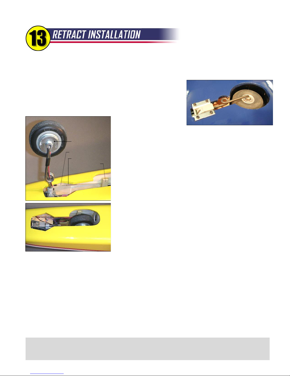
I love Robart's retracts, but their installation instructions are pretty skimpy. If you are new to retracts,
the following tips may help. The Retract package from BTE provides all of the hardware and steering
accessories that are needed. The Wheel and Brake package from BTE simplifies the brake installation.
Main Wheel Retract Units - The wing has been pretty well prepared for
these. Attach two air lines to the unit, then bolt it in place. Keep the color-
Main Wheel
Retract
coded air lines consistent throughout your retract installation - one is for
"wheels up" air and the other is for "wheels down" air. The air lines need to
be routed through the holes in W-7 and the servo lead tube to the center of
the wing. At the center, connect
the like-colored lines with a Tfitting, and add a short third line that comes out of the wing and ends at a
quick disconnect. I suggest using a male disconnect on one line, and a
Kavan Brake
Steering Cable
Nylon Tube
Tube Clamp
female on the other so there's no way to hook it up backwards when you're
at the field.
Nose Wheel Retract Unit - Grab your knife and cut a hole in the fuselage
bottom sheeting for the nose retract unit. The hole needs to be at least big
enough to get the unit in and out. Hook up your air lines, then bolt the unit
to both F-2 and the receiver shelf. The hole in the fuselage will have to be
enlarged to clear the nose wheel and strut.
Nose Wheel Steering - The Robart unit requires a pull-pull cable system
for steering. When the gear is extended, the cables need to be fairly tight
to operate properly. When retracted, the cables go slack and you must
provide some means to pull them out of the way so they don't get tangled
up with the wheel and strut. Some modelers use rubber bands looped
around cables and fastened to hooks on the fuselage sides. I used nylon
Typical Nose Wheel Cutout
tubes instead. The tubes are 6" long, but only glued to the side in a small
spot near the center. When the wheel is retracted, the tubes straighten out
along the fuselage sides. When extended, the tubes are flexible enough to
pull into position. Works great! You only need a small amount of movement in the nose wheel, maybe 15º each
direction for good ground handling.
Air Tank - The medium-size Robart tank is total overkill for these retracts, but it fits so why not? Pump it up to 100 psi
and you are probably good for twenty retract cycles. If you prefer, you can go with a small tank which would be good
for a dozen cycles or so.
Retract Valve - Make a plywood bracket for mounting the valve. Its mechanism only slides about 1/4" total, so you
will need to program your retract servo for a small amount of movement. In my original installation, I didn't use a
computer radio so the servo travel was cut down mechanically using a bellcrank.
Filler and Pressure Gauge - Suggested mounting positions for these items are shown on the plans. To pressurize
the system, I use Robart's hand pump (good exercise!), but most builders use an electric compressor. R54
31
New for 2014 - BTE now offers Robart electric retracts for the R54. They are identical to the pneumatics offered in
previous years except the air cylinders have been replaced with electric actuators. Follow the installation guidelines
provided with the Robart package. Note: The W-7 wing ribs will need a notch to clear the longer electric actuators.
Page 33
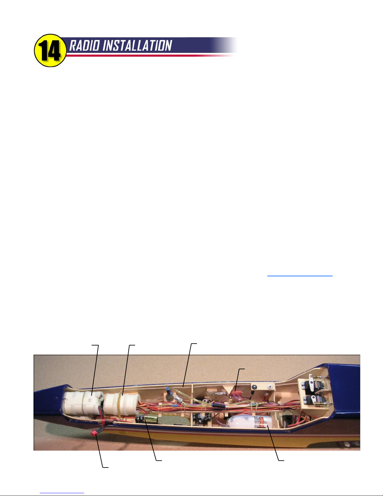
In turbine models, neatness counts! Pay attention to the details and you will be rewarded with jet that is
reliable and easy to maintain.
Receiver - Position the receiver in the nose to help with nose weight and to separate it from the ECU. Wrap it in foam
rubber, not for vibration protection but for crash protection. The hatch bulkhead H-2 may need to be cut away at the
bottom to make room for the receiver.
Battery - Again, the radio battery is located in the nose for nose weight and wrapped in foam for crash protection.
Many modelers like to use two batteries for redundancy. Use high-quality components and stay on top of your battery
condition at all times. Remember, most radio failures in models of all types are battery related.
Switch - It is important to make the switch (or switches) accessible. With it mounted to the receiver shelf, it appears to
be covered by the ECU battery, but it's still easy to access and this hasn't caused me any trouble in the field. Make
sure the switch cannot be bumped off accidentally by the battery (or anything else) shifting in flight.
Servos - Installation of the elevator and rudder servos was pretty well covered during construction. The wing servos
are mounted using the hardware supplied with the servos. The pushrods for the ailerons and flaps are shown in detail
on the plans. Note the position of the servo arms for each control surface. The steering and retract servos can be
mounted to basswood rails aft of F-3. Try to get the rails as low as possible in the fuselage, not only to align the
steering servo favorably with the nose wheel retract unit, but also to leave room to get the retract air tank in and out. If
you use bigger servos or mount the rails higher, you may have to put the tank in first and consider it "built in".
Servo Extensions - You will need a variety of servo extensions for the R54. Don't skimp here - use high-quality,
heavy-duty leads from reputable sources. I buy all my extensions and switches from www.electrodynam.com
Wiring Rack - The plans and photos show the balsa wiring rack that I developed for this model. It's a handy way to
bundle all the servo leads and air lines running back and forth in the forward fuselage. The rubber bands (included in
the kit) allow quick and easy maintenance if you ever need to change a wire or air line. The wiring rack itself is held to
small basswood blocks on F-3 and F-4 using two flat-head screws. Countersink the balsa for the screws so they won't
interfere with the wiring. R54
ECU Battery
Receiver
Antenna - keep it separated from all other wiring
32
Receiver Battery
is under the ECU
Battery
9V Battery for Kavan Brake
ECU Battery Connector - disconnect between flights
Retract Valve
Retract Air Tank - wrap
with tape for snug fit in F-4
Page 34
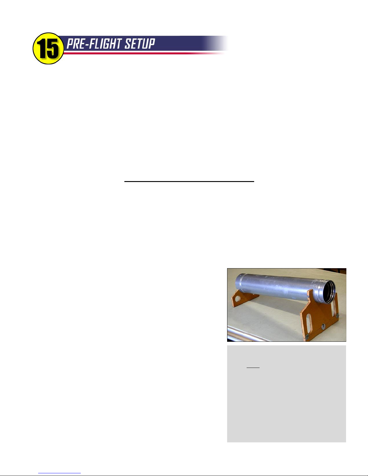
BALANCE
Your R54 must balance in the range shown on the plans, with the UAT full of fuel (since it is behind the CG) and the
gear retracted. Do not exceed the rear limit! In general, it easiest to balance the R54 upside down. Most likely, you
will need to add some lead to the nose. The nose block cavity will hold a fair amount of lead shot, but you may need
even more. Every modeler hates to add dead weight, but grit your teeth and add enough to be in the forward half of
the balance range for the first flight. You can put lead shot in small plastic bags which can be removed later as
desired. Be sure to also check the lateral balance and add weight to one of the wingtips if necessary to balance.
CONTROL THROWS
Adjust the amount of control surface deflection to the amounts shown below. These are fairly active settings - go easy
on the sticks for the first flight or two, then adjust the control throws to suit your flying style.
RECOMMENDED CONTROL THROWS
AILERONS: 3/4" UP, 5/8" DOWN
ELEVATOR: 5/8" UP, 5/8" DOWN
RUDDER: 1-1/2" LEFT, 1-1/2" RIGHT
FLAP DEFLECTION: FULL MOVEMENT (60°)
DOWN ELEVATOR WITH FULL FLAPS: 1/8"
Notice the ailerons should move UP more than DOWN. This aileron differential helps combat adverse yaw, making for
smoother rolls. If you like rates or exponential, but go ahead and program them in if you wish. Automatic DOWN
elevator compensation is helpful to counteract the nose-up tendency of the model when the flaps are deployed. This
is a common feature found on many modern radios.
PRE-FLIGHT INSPECTION
Be sure to perform radio range checks, both with the turbine off AND
with it running. If there is a significant decrease in the range with the
engine running, you may need to reposition your components or reroute the antenna. Keep in mind that even though this is a big
airplane, it's the little things that will "getcha". Double check all of your
servo arm screws, clevises, pushrods, nuts, bolts, hinges, cables, and
fuel tank connections. Triple check that your flight controls are all
moving in the proper direction.
AN IMPORTANT SAFETY NOTE
You also need a positive way of shutting off the engine from the
transmitter, either using full idle trim or a separate channel to switch off
the turbine instantly. If you have any trouble during flight, the most
important thing you can do as a pilot is to shut off the turbine without
hesitation. The chance of a post-crash fire is greatly diminished if you
get the turbine shut down before impact. With its huge wing, the R54
can glide in for a safe landing from nearly anywhere if you still have
control (a nice feature for flameouts - believe me!). R54
Start Tube - I consider it mandatory to use
some sort of flame protection for the model
during every turbine start up. A hot start could
obviously cause a problem, but even normal
starts often produce a small flame and hot,
slow-moving exhaust gases that can scorch
Monokote. I use this start tube made from
double-walled stovepipe with plywood legs.
Notice the hinged extension at the bottom of the
front plywood leg. The height can be changed
so it works with both my R54 and my PST
Reaction ARF. Warn helpers to grab the
plywood after starting - the tube will be hot!
33
Page 35
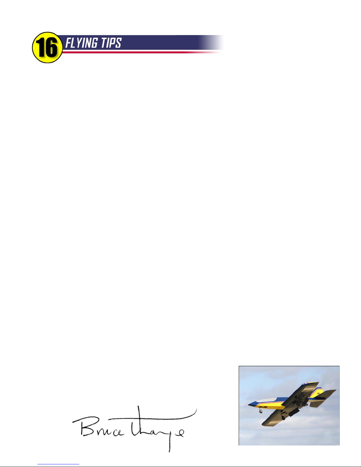
It is hard to describe the feeling you get, standing at the edge of the runway, listening to your turbine spool up and
watching your jet begin to accelerate for its maiden flight. I won't try. For many builders, the R54 will be their first
experience with a turbine. All I can say is take it all in because it's a feeling you won't forget for a long, long time.
If you live in the United States, there are some hoops that you need to jump through. The AMA does provide liability
protection for turbine pilots, but you must obtain a special waiver. The details can be found on the AMA website. To
earn your waiver you basically need to prove that you are a competent pilot by performing a demonstration flight in
front of two experienced turbine pilots, one of whom is a contest director. You can actually do the demo with your
R54, but all of your test flights leading up to the exam must be done on a buddy box. Yes, it is a pain, but I commend
the AMA for working with the jet community and instituting this set of safety regulations. The future of turbine model
flying, and perhaps all R/C modeling, depends on our commitment to safety and personal responsibility.
When you transition from prop planes to turbines, the most noticeable difference is the turbine throttle lag. It will take
some time to get used to this, but the forgiving nature of the R54 will help you get through this learning curve without
difficulty. Due to the relative speed of turbine models and the throttle lag, jet pilots need to be constantly thinking
ahead, particularly during the landing approach. Decide early if you need to go around and don't hesitate to do it.
The R54 is great for short fields, but if this is your first turbine model I strongly suggest that you find a nice long runway
for your initial flights, even if you have to drive an extra hour or two. Once you get a feel for the model’s handling
characteristics, you will be ready to try it from your shorter local sites.
Enough paperwork and warnings - let's fly! There is really nothing tricky about flying the R54. Takeoffs on pavement
typically use up about 150 ft. of runway. Grass runways will obviously require more distance. The R54 climbs out
briskly. Bring the gear up and trim the model for smooth level flight with the throttle at about 2/3 or 3/4. It should be
cruising around at something less than 100 mph. On your maiden flight be sure to climb to altitude, drop the gear and
flaps, and reduce the throttle to 1/2 or less to get a feel for its amazing slow-flying capabilities.
When you are ready to wring her out, you will find the R54 excels at smooth, jet-style aerobatics. The rudder is too
small for snaps or spins, but it is adequate to hold a knife edge clear across the horizon. The R54 is designed for
aerobatics, not speed, so use some common sense when it comes to throttle management. Full throttle should be
reserved for takeoffs, climbing, and the occasional fast pass. If the nose is pointed down, throttle back.
Landings are slow and easy with the R54. The only time I've gotten into trouble is when I've tried to let off the back
pressure on the elevator during final. My best advice for landing is to just let the model slow down at its own pace and
settle onto the runway when it's good and ready. Pretty soon your landings will be so nice that you will begin doing
what very few "heavy jet" pilots dare: touch-and-goes!
When you taxi back, be sure to get one last whiff of that sweet aroma of jet
exhaust before shutting down. I sincerely hope you enjoy the Reaction 54,
both at the building board and at the field. Be sure to send me a photo of
your finished model. Thank You!
34
Page 36

Appendix A 35
Engines
The Reaction 54 is designed for tubines in what is commonly known as the "12-lb. Class". The BTE prototype models
have been thoroughly tested with a RAM 500 which puts out 11+ pounds of thrust and a PST J600R which puts out 14
lbs. of thrust. Therefore, the R54 airframe is rated for a maximum thrust of 14 lbs. Through continued refinement, the
engines in this class are now putting out more power. If necessary, limit the thrust of your turbine by programming
your ECU to a new, lower maximum rpm (check with the manufacturer for the proper rpm setting). A list of suitable
turbines is presented on the next page.
Radio and Servos
You will need at least a six-channel radio for the R54. To comply with AMA Safety Regulations, all radios used in
turbine-powered models must be equipped with fail safe and ECUs shall be configured to shut down the engine within
two seconds of fail safe activation. You will also need some mixing functions, primarily to add a bit of down elevator
with flap deployment. Personally, I have settled on the Futaba 9C transmitter because it is easy to program, has lots
of mixing functions, and has slider switches for flaps, which I consider much easier to use than knobs.
Every turbine pilot has their own opinion on servos. This is an entry-level turbine model designed to fly at modest
speeds with an eye towards economy. The place to economize, however, is not with your servos! Digital servos are
mandatory for all of the flight control surfaces. Prices for digitals are coming down, and there is a wide selection from
all the radio manufacturers. Digital servos also offer an extra level of security against flutter thanks to their ability to
“lock in” around neutral. There have been no problems with the Hitec servos used in the prototypes, so I will use their
specifications as minimum requirements, as follows:
Ailerons (2 servos) and Rudder (1 servo) Hitec HS-5625MG - 110 oz.in. @ 4.8V Dual BB, Metal Gears
Flaps (2 servos) and Elevator (1 servo) Hitec HS-5645MG - 143 oz.in. @ 4.8V Dual BB, Metal Gears
Nosewheel Steering (1) and Retract Valve (1) Hitec HS-225MG - 54 oz. in. @ 4.8V Top BB, Metal Gears
Retracts
The R54 was designed around the Robart 500-series retracts. The Retract Package from BTE uses Robart #530 units
for the main wheels and #563 for the nose wheel. The nose wheel unit was particularly attractive to me because it has
mounting holes for both firewall and belly mounting. It seemed natural to me to design the model to utilize both sets of
mounting flanges for maximum strength, and it has proven its strength in flight testing several times. (Translated: I've
made some really bad landings that should have torn the gear out, but both the Robart gear and the airframe took the
punishment with no damage beyond bent struts!). There are other retract units on the market that can be substituted,
but I haven't tried them and cannot recommend their use. If you want to try different retracts, it will be up to you to
engineer their installation.
Header Tank / Air Trap
In addition to the Du-Bro 60 ounce fuel tank, I recommend using a header tank for reliable fuel flow to the turbine. The
most popular header tank in use today is the BVM Ultimate Air Trap (UAT). It is what I used in the prototypes and is
shown on the plans. The UAT is a special header tank that incorporates a fibrous bag to trap air bubbles, preventing
them from getting to your turbine and possibly causing a flameout. It holds four ounces of fuel, bringing the total fuel
load to 64 oz. There are several less expensive alternatives on the market now and they should all work fine. Visit
www.dreamworksrc.com for a wide selection of header tanks and lots of other turbine-related products.
Page 37
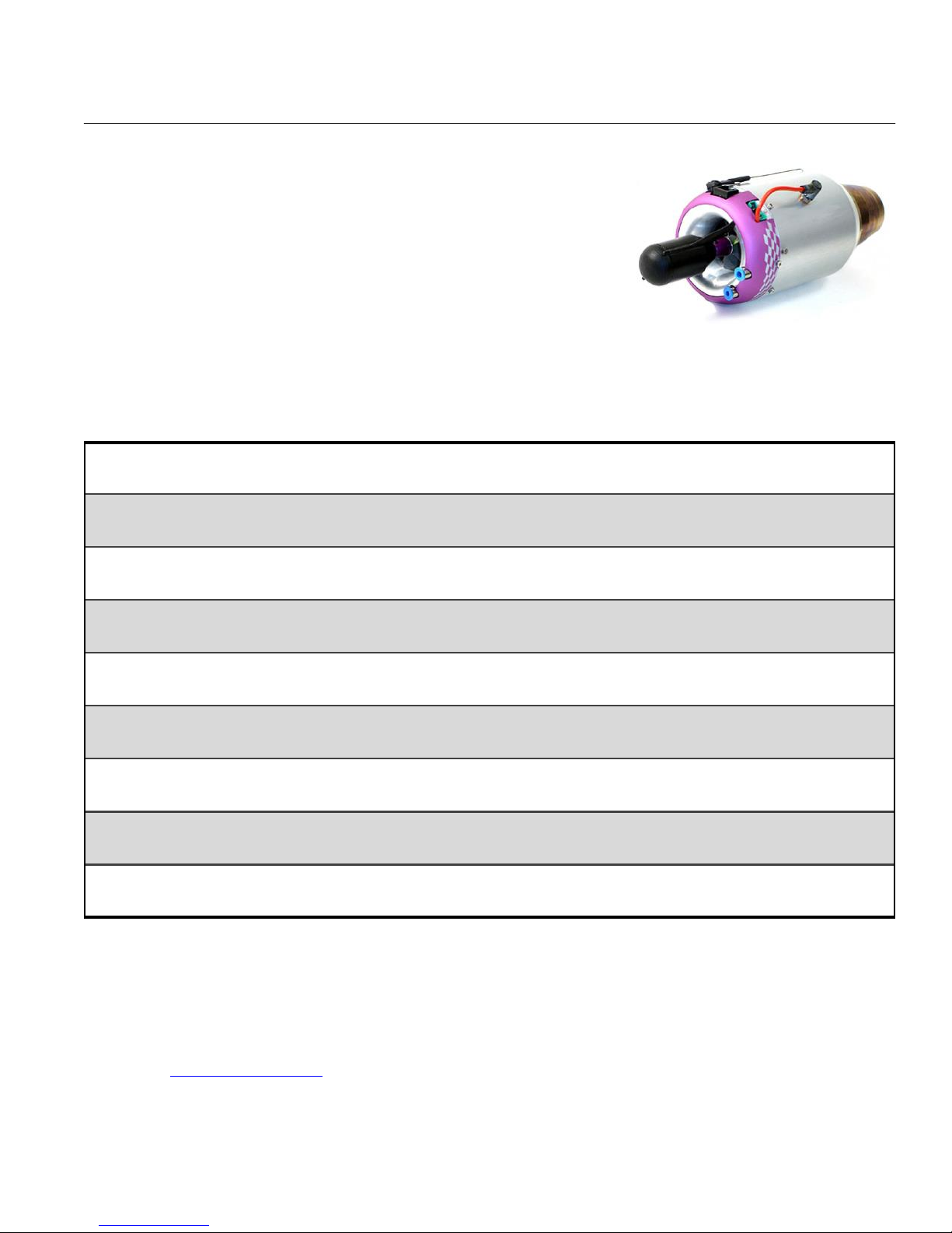
RECOMMENDED EQUIPMENT, continued...
Appendix A 36
Recommended Engine List
The Reaction 54 is designed to accommodate tubines in what is commonly
known as the "60N Class" (“N” is for Newton, a measure of force). Most of
these engines are based on a design pioneered by the Wren company in
England which used a 54mm diameter compressor wheel. In fact, Wren
supplied the critical turbine wheel for many of the early engines in this class.
The chart shown here is a list of turbines that are suitable for the R54. Most of
the information is taken from the websites of each company. Things change
fast in the turbine business, so please use this list as a starting point for your
JetCat P60-SE
research into the ideal turbine for your Reaction 54. Engines are shown in
alphabetical order.
Company/Turbine Made In Max Thrust RPM Range Diameter Weight
JetCat P60-SE Germany 13 lb. 50,000 - 165,000 3.25” 1.87 lb.
Comments: "Undersize" turbine that is light and powerful. Gas start. Great runner, great support. BTE Combo Deal!
JetCat P-70 Germany 17.5 lb. 35,000 - 123,000 3.7” 2.6 lb.
Comments: Oversize, but will fit on R54. No longer available, but used ones can be found.
Jet Central Bee II Mexico 14 lb. 55,000 - 180,000 3.15" 1.7 lb.
Comments: Well-established turbine. Smaller diameter than typical "54". Gas or kero start. BTE Combo Deal!
KingTech K-60G Taiwan 13.22 lb. 50,000 - 162,000 3.22" 1.88 lb.
Comments: Tight, light unit features kero start. Great price, and building a great reputation. BTE Combo Deal!
KingTech K-80G Taiwan 19 lb. 45,000 - 145,000 3.75" 2.88 lb.
Comments: Big and heavy for R54, but powerful. K-60G is a better choice for this plane. BTE Combo Deal!
PST J600R Thailand 14 lb. 55,000 - 160,000 3.5" 2.2 lb.
Comments: Beautifully-made Wren-based engine. Full Autostart. Shown on plans.
PST J800R Thailand 18 lb. 55,000 - 153,000 3.5" 2.2 lb.
Comments: Larger and heavier than the J600R. Full Autostart. Built-in FOD screen.
Wren 80 i-Kero England 18 lb. 50,000 - 160,000 3.5" 2.2 lb.
Comments: Ultra-efficient, optimized MW-54. Same size, more power. Factory assembled only.
Larger Turbines - The great modeling tradition of trying to shoehorn as big an engine as possible into an airframe can
get you in trouble with the R54. The next larger turbines over the ones listed here are physically too large to fit in the
intended engine area of the R54. Besides that, their weight and higher idle thrust are both problematic. Bottom line:
Don't use them on the R54.
Please visit www.btemodels.com for more information on how to save money with a BTE Combo Deal! R54
Page 38

Appendix B 37
Robart Electric Retract Package – Includes everything you need to install retracts in your R54: Robart 500-series
retract units (two main, one nose), special-bent 3/16” wire struts designed exclusively for the R54, electronic controller,
two 12” extensions with locking connectors, retract mounting hardware, complete nose wheel pull-pull steering linkage
as shown on the kit plans. BTE Price . . . . . . $399.95
About the Robart Retracts
There may be other suitable retracts out there, but these have proven their durability from pavement and grass fields alike..
Robart quality and value is second to none. Pneumatic retracts are still available in limited supply - call BTE for price.
Wheel and Brake Package – Includes two 3” Sullivan Sky-Lite main wheels, a 3” Hangar 9 Pro-Lite nose wheel,
Kavan electro-magnetic brake, microswitch, 9V battery connector, Deans connector, brass tubing for wheel bearings,
wheel collars, mounting hardware, and instructions. Total Retail Price $108.67 BTE Price . . . . . . $89.95
About the Kavan Brake
The R54 lands so slow that a brake is not really required, but AMA turbine regulations require some sort of braking device. The
Kavan unit is inexpensive, especially compared to a pneumatic system. It mounts on the nose wheel, so it also provides a chu nk
of nose weight, which is needed anyway. It is activated by a micro switch that is contacted by the elevator servo arm at full
down elevator. In my mind, this is the ideal brake system for the R54.
Replacement Wheel Package – Includes two 3” Sullivan Sky-Lite main wheels, a 3” Hangar 9 Pro-Lite nose wheel,
and brass tubing for optional bearings. Retail Price $27.60 BTE Price . . . . . . $17.95
About the Replacement Wheels
A low-speed model like the R54 does not need special, high-priced “jet” wheels and tires. These sport R/C wheels handle rough
terrain with no problem and the tires have never rolled off the rim even after some bad landings with high side loads. I did
replace mine after about sixty landings on pavement. Considering the price, I can live with that!
Fuel System Package – Includes SWB machined-aluminum fuel tank cap, Du-Bro fuel line barbs, safety wire for all
connections, Tygon tubing for vent line, Du-Bro Fuel-It receptacle and plug for vent line, tie-wraps for mounting your
UAT* and fuel pump*, Velcro for mounting your solenoids*, and fiberglass tubes for aligning the fuel tubing going to
your shut-off valve* as shown on the plans. * Not included in package. Retail Price $28.46 BTE Price . . . . . . $21.95
About the Fuel System Package
This is a low-cost package that brings together everything you need (except the UAT) to finish off your fuel system. As discussed
in Appendix A, a UAT or some other header tank must be purchased separately. The red anodized SWB cap is a high-tech
replacement for the nylon cap that comes with the Du-Bro fuel tank. The Fuel-It receptacle and plug are provided because I
have found that kerosene loves to dribble from the vent line at the worst times, like in your vehicle!
Handibond CA Package – Includes one 2 oz. Thin CA, two 2 oz. Medium CA, one 2 oz. Thick CA, one 2 oz.
Accelerator Spray, micro-tips, and extra-long glue tip. Retail Price $34.76 BTE Price . . . . . . $29.95
About the Handibond Package
This package of cyanoacrylate adhesives (CA) is tailored directly to the R54 kit. Use the thin CA for general construction and
easy hinges. The extra-long glue tip is included to use when applying the leading edge sheeting (as described on page 9). In
addition to the CA, I recommend purchasing some aliphatic resin (yellow glue like Tite-Bond or Elmers wood glue) and some
slow-dry (3 hr.) epoxy. The instruction book often specifies certain glues for certain steps.
Corner Sanding Tool (Exclusive BTE Product, see page 25) BTE Price . . . . . $14.95
Fourmost Sanding Stick with Sandpaper Retail Price $6.90 BTE Price . . . . . . $5.00
Robart #164G Air Pump (Hand-Operated, 100 psi +) BTE Price . . . . . $35.95
Full-Size BTE Color Scheme Templates (Six Large Sheets) BTE Price . . . . . $29.95
Disposable Scissors (for cutting the stainless steel heat shield) BTE Price . . . . . . $1.95
Page 39
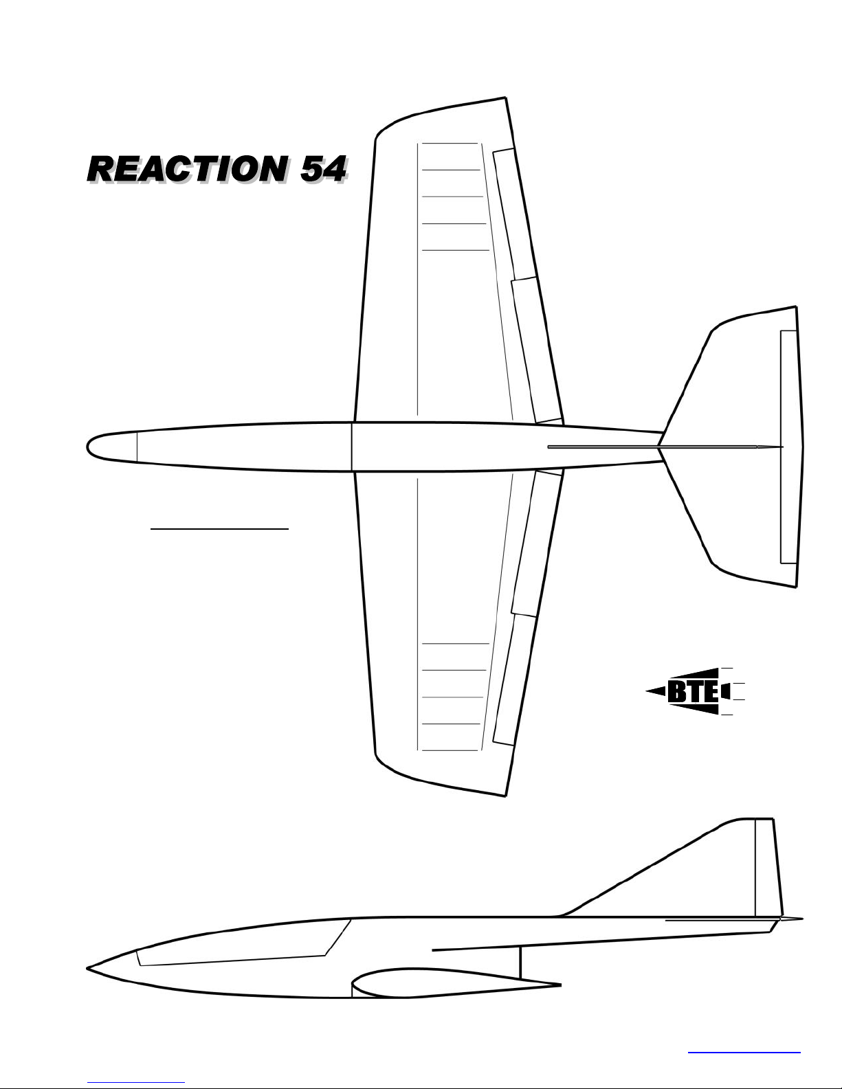
Designed by
Bruce Tharpe
Appendix C 38
SPECIFICATIONS
Wingspan
Wing Area
Root Chord
Tip Chord
Mean Aero. Chord
CG Range at MAC
Root Airfoil
Tip Airfoil
Washout
LE Radius
Overall Length
Stabilizer Span
Stabilizer Area
Fin Area
Engines
Thrust Angle
Structure
Landing Gear
Design Weight
78 inches
1453 sq. inches
24 inches
15.5 inches
19.7 inches
25% - 30%
BTE 13.8% thick
BTE 13.4% thick
1/2º
3/8 inch Constant
80 inches
31.4 inches
361 sq. inches
161 sq. inches
12-14 lb Turbines
6.5º nose up
All Wood
Retractable Tricycle
17 pounds
BRUCE THARPE ENGINEERING 8622 E EVANS CREEK ROAD, ROGUE RIVER, OR 97537 541-582-1708 www.btemodels.com
Page 40

Appendix D: REACTION 54 COMPLETE PARTS LIST
Some parts may be stuck together with a spray adhesive used in manufacturing. They should be easy to pry apart. Sand them lightly to remove residue.
BALSA STICKS FUSELAGE PARTS BAG
4 3/32 x 3/8 x 36 Balsa 2 5/16 x 2-1/2 x 2-1/2 Balsa Servo Mount Braces (big triangles)
4 3/16 x 3/8 x 36 Balsa Trailing Edge Spars 2 1/8 x 1-5/8 x 2-3/4 Lite-Ply
3 5/16 x 5/16 x 36 Balsa 2 1/8 x 2-1/4 x 3-5/8 Lite-Ply
1 5/16 x 1/2 x 36 Balsa Fin Posts, Temporary Braces 1 1/8 x 2 x 3-1/2 Lite-Ply H-2 Hatch Bulkhead
1 1/4 x 1 x 36 Balsa Wiring Rack, Tank Rails, Tube Guides 1 1/8 x 1-5/8 x 2-1/2 Lite-Ply F-1
1 3/8 x 3/8 x 36 Balsa Stabilizer Leading Edge 1 1/8 x 4-1/2 x 6-7/8 Lite-Ply F-3 & H-3 (to be separated by builder)
2 3/8 x 3/8 x 36 Balsa Shaped Leading Edges 1 1/8 x 5 x 8 Lite-Ply F-4 & H-4 (to be separated by builder)
2 1/2 x 9/16 x 24 Balsa Shaped Trailing Edges - Outboard 1 1/8 x 5 x 8-3/8 Lite-Ply F-5
2 1/2 x 11/16 x 24 Balsa Shaped Trailing Edges - Inboard 2 1/8 x 1-3/4 x 5 Lite-Ply
4 1/2 Triangle x 36 Balsa Corner Reinforcements 1 1/8 x 5 x 5-1/2 Lite-Ply F-6
2 1/2 Triangle x 36 Balsa Corner Reinforcements (trimmed edge) 1 1/8 x 1-1/2 x 4-3/8 Lite-Ply F-7 Front Turbine Mount Bulkhead
1 3/4 Triangle x 18 Balsa Landing Gear Mount Reinforcements 1 1/8 x 1-1/2 x 3-7/8 Lite-Ply
HARDWOOD STICKS
2 1/8 x 3/8 x 12 Lite-Ply Reinforcements 2 1/8 x 2 x 3 Lite-Ply Hatch Tongues
2 1/4 x 3/8 x 12 Bass Servo Rails, Rear Hatch Rails, J-Bolt Pads 1 1/8 x 3-3/4 x 4-1/4 Lite-Ply Receiver Shelf
4 1/4 x 1/2 x 36 Spruce Top Main Spar, Top & Bottom Stub Spar 1 1/8 x 3-7/8 x 4-3/4 Lite-Ply ECU Shelf
2 1/4 x 1/2 x 36 Spruce Bottom Main Spar (beveled edge) 1 1/8 x 5 x 8-7/8 Lite-Ply Tank Compartment Top
2 1/4 x 1/2 x 12 Spruce Top Main Spar Doubler 1 1/32 x 1/2 x 1 AC Ply Rear Hatch Tab
2 1/4 x 1/2 x 12 Spruce Bottom Main Spar Doubler (beveled edge) 1 3/32 x 4-1/4 x 5 AC Ply Turbine Mount
BALSA SHEETS
6 3/32 x 3 x 36 Balsa Trailing Edge Sheeting, Shear Webs 1 1/4 x 1/2 x 3 AC Ply H-1 Front Hatch Bulkhead
6 3/32 x 4 x 7-1/2 Balsa Wingtip Sheeting, Fuselage Sheeting 1 1/4 x 1-1/2 x 3-1/2 AC Ply F-2 Nose Retract Mount
18 3/32 x 4 x 36 Balsa LE & Center Sheeting, Fuselage Sheeting 1 3/8 x 1-1/2 x 2-3/8 AC Ply Wing Mount
4 1/4 x 4 x 36 Balsa Fuselage Sheeting 1 3/8 x 3/4 x 1 Poplar
WING RIBS
2 3/32 x 20-1/4 Balsa W-1 Wing Rib
2 3/32 x 19-3/4 Balsa W-2 Wing Rib 1 3/8 x 1-1/4 x 3 Balsa Material for Fuselage Fairing Sides
2 3/32 x 19 Balsa W-3 Wing Rib 2 1/8 x 4-1/2 x 5-1/2 Lite-Ply Wheel Well Frames and Floors
2 3/32 x 18-1/2 Balsa W-4 Wing Rib 4 1/8 x 2-1/4 x 5-1/2 Lite-Ply
2 3/32 x 17-3/4 Balsa W-5 Wing Rib 2 1/8 x 2-3/4 x 3-1/2 Lite-Ply
2 3/32 x 17 Balsa W-6 Wing Rib 2 1/8 x 2-3/8 x 3 Lite-Ply Flap Servo Mounts
2 3/32 x 16-1/4 Balsa W-7 Wing Rib 2 1/8 x 2-7/8 x 4 Lite-Ply Aileron Servo Mounts
2 3/32 x 15-1/2 Balsa W-8 Wing Rib 2 1/8 x 1/2 x 4-1/2 Lite-Ply Wing Hatch Rails
2 3/32 x 15-1/2 Balsa W-9 Wing Rib 2 1/8 x 2-1/2 x 3 Lite -Ply SWDG Shear Web / Dihedral Gauge
2 3/32 x 14-1/2 Balsa W-10 Wing Rib 1 1/8 x 1-1/2 x 5-1/2 Lite-Ply Fuselage Fairing Face Plate
2 3/32 x 13-3/4 Balsa W-11 Wing Rib 6 1/16 x 1 x 1 AC Ply Control Horn Pads
2 3/32 x 13 Balsa W-12 Wing Rib 1 3/32 x 15/16 x 2-1/4 AC Ply Wing Bolt Plate
2 3/32 x 12-3/8 Balsa W-13 Wing Rib 2 1/8 x 4-1/2 x 4-1/2 AC Ply Retract Mounts
2 3/32 x 12-1/4 Balsa W-14 Wing Rib 4 1/8 x 1/3/4 x 5-1/2 AC Ply
Capstrips, Wiring Rack
D-1 Receiver Shelf Positioner
Longerons, Rudder Caps, Braces D-2 ECU Shelf Positioner
F-5D (doublers for F-5)
F-8 Rear Turbine Mount Bulkead
1 1/8 x 2-1/2 x 4-3/4 Lite-Ply Servo Mount
1 1/8 x 2-1/2 x 3 Lite-Ply Servo Mount Doubler
2 3/16 x 5/8 x 1-1/4 AC Ply Latch Retainers (grooved edge)
1 3/16 x 1-1/2 x 4 AC Ply Turbine Mount Doubler
Pushrod Housing Clamp
1 3/8 x 2 x 2 Poplar Thrust Wedge
WING PARTS BAG
W-6D Rib Doublers
Dowel Block Doublers (partial rib)
Retract Mount Doublers
2 Birch Wing Dowels
1/4 dia. x 4
Page 41

REACTION 54 PARTS LIST - CONTINUED
MACHINED BALSA FUSELAGE PARTS HARDWARE
2 1/4 x 4 x 36 Balsa SIDE-1 (notched, left and right) 12 #2 x 3/8 Truss Head Steel Sheet Metal Screw (wing hatches)
2 1/4 x 1 x 10 Balsa SIDE-2 4 #2 x1/2 Pan Head Steel Sheet Metal Screw (rudder control horn)
2 1/4 x 4 x 36 Balsa SIDE-3 20 #2 x 3/4 Pan Head Steel Sheet Metal Screw (all other control horns)
2 1/4 x 2 x 19 Balsa SIDE-4 2 #4 x 3/4 Flat Head Steel Sheet Metal Screw (wire rack)
2 1/4 x 4 x 27 Balsa Hatch Side/SIDE-5 4 #6 x 1 Pan Head St Steel Sheet Metal Screw (turbine mount)
1 1/4 x 3 x 13-1/2 Balsa Stabilizer Mount 6 4-40 Steel Hex Nuts (use for clevis jam nuts)
1 2-1/4 x 3 x 3 Balsa Nose Block 2 1/4 -20 x 3 Rd Head Alum Wing Bolts (may be shortened to 2.5")
2 Nylon Flat Washers (for wing bolts)
1/4 i.d. x 3/4 o.d.
MACHINED BALSA FIN/RUDDER PARTS
1 5/16 x 3 x 10 Balsa FIN-1 6 4-40 Steel Solder Clevis (1 per control surface)
1 5/16 x 3 x 8-1/2 Balsa FIN-2 6 4-40 Steel Sure-Lock Clevis (1 per control surface)
1 5/16 x 3 x 6-3/4 Balsa FIN-3 6 3/16 x 1/4 Steel Locking Clips (1 per clevis)
1 5/16 x 3 x 5-1/4 Balsa FIN-4 3 Short (3/4") Steel Control Horns (2 flap, 1 rudder)
1 5/16 x 3 x 3-1/2 Balsa FIN-5 3 Long (1-1/8") Steel Control Horns (2 aileron, 1 elevator)
1 5/16 x 3 x 1-3/4 Balsa FIN-6 6 5/8 x 7/8 Nylon Control Horn Backing Plates
1 5/16 x 2 x 25 Balsa FIN-7 Fin Front 1 5/8 x 1-7/8 Metal Hatch Latch (assembled)
1 5/16 x 3 x 10-3/8 Balsa Rudder (tapered and beveled) 4 4-40 x 6 Steel Threaded Rod (2 aileron, 2 flap)
MACHINED BALSA STAB/ELEVATOR PARTS
2 3/8 x 2-1/4 x 5 Balsa STAB-1 20 #10 Rubber Rubber Bands (wire rack, rear hatch)
1 3/8 x 2-3/4 x 22 Balsa STAB-2 32 3/4 x 1 Secret
3 3/8 x 2-3/4 x 26 Balsa STAB-3
2 3/8 x 2-2/4 x 9-1/2 Balsa STAB-4 Stabilizer Tips
1 3/8 x 2-1/4 x 26 Balsa Elevator (tapered and beveled) 4 36 x 48 Paper Full-Size Plans - Wing Panels, Fuselage
MACHINED BALSA WING PARTS
2 1 x 2-1/2 x 3 Balsa Wing Dowel Supports 3 8-1/2 x 14 Paper Servo Lead Tubes
1 1 x 3 x 4 Balsa Wing Bolt Supports 1 60 oz. Nylon Du-Bro Fuel Tank (with hardware)
2 1-1/2 x 2 x 15-1/2 Balsa Wingtips 1 3/16 x 3 x 3 Foam Fuel Tank Pad - Front
2 5/8 x 2-1/2 x 6 Balsa Tip TE Extensions (tapered) 1 1/2 x 4-3/4 x 9 Foam Fuel Tank Pad - Top
1 5/8 x 2-1/2 x 30 Balsa Ailerons (tapered and beveled) 1 .003 x 6 x 8 St Steel Heat Shield Material
2 3/4 x 3 x 3-1/2 Balsa Root TE Extensions (tapered) 1 1-1/2 x 10 Alum Tape (to finish edge of heat shield)
1 3/4 x 3 x 32-1/2 Balsa Flaps (tapered and beveled) 1 2 x 56 Glass Fiberglass Tape (for wing center joint)
LOOSE PLYWOOD PARTS
2 1/8 x 7-1/4 x 35 Lite-Ply 1 Steel
2 1/8 x 3-3/4 x 10 Lite-Ply Boat Tail Sides 1 Nylon Cable Housing (nylon tube)
2 1/8 x 5-1/4 x 9-1/2 Lite-Ply Boat Tail Formers 1 4-1/4 x 11 Paper Template Sheet (blue card stock)
1 1/8 x 2-3/4 x 9-1/2 Lite-Ply Boat Tail Jig 1 .090 Alum Turbine Mounting Bracket*
2 1/32 x 1-7/8 x 12 AC Ply Wheel Well Liner
1 1/4 x 2 x 10 AC Ply Rear Dihedral Brace *Several Styles Available to Suit Different Turbines
1 1/4 x 2 x 15 AC Ply Front Dihedral Brace
Fuselage Doublers 3/32 dia. x 98 Stranded Cable (elev & rud linkage)
2 4-40 Steel Threaded Couplers (elevator, rudder)
8 5/8" Brass Cup Hooks (4 rear hatch, 4 hold downs)
1 Rubber Grommet (for turbine wiring at fuselage)
1/2" i.d. x 1" o.d.
Sig Easy Hinges (one extra)
MISCELLANEOUS
1 24 x 36 Paper Full-Size Plan - Stabilizer
1 40 Pages Paper Instruction Book with Color Photos
1 1-3/4 x 16 Vinyl Graphic - Reaction 54 Logo (black)
1 2-1/2 x 9 Vinyl Graphic - BTE Logos (black)
3/16 o.d. x 98
 Loading...