

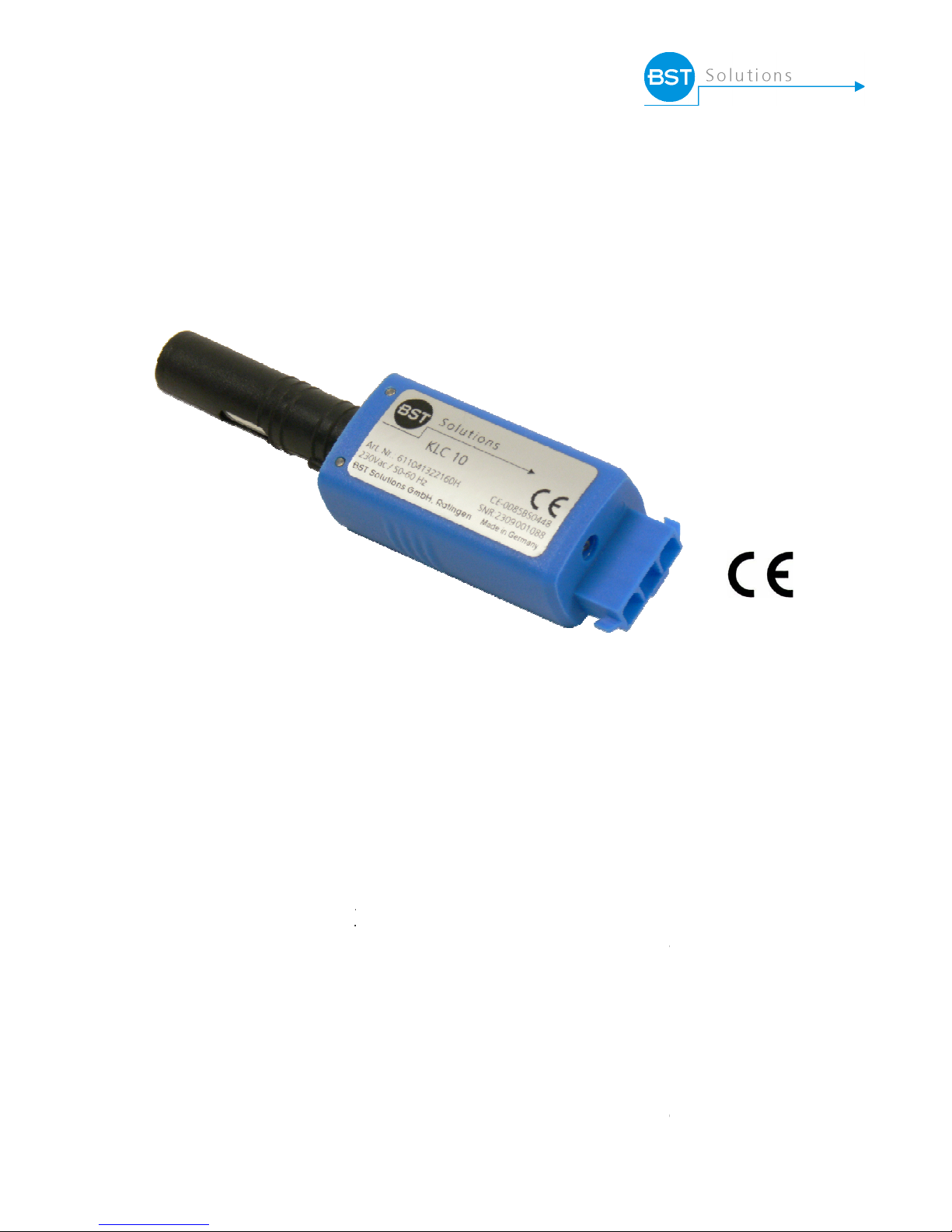
KLC 10
Technical information
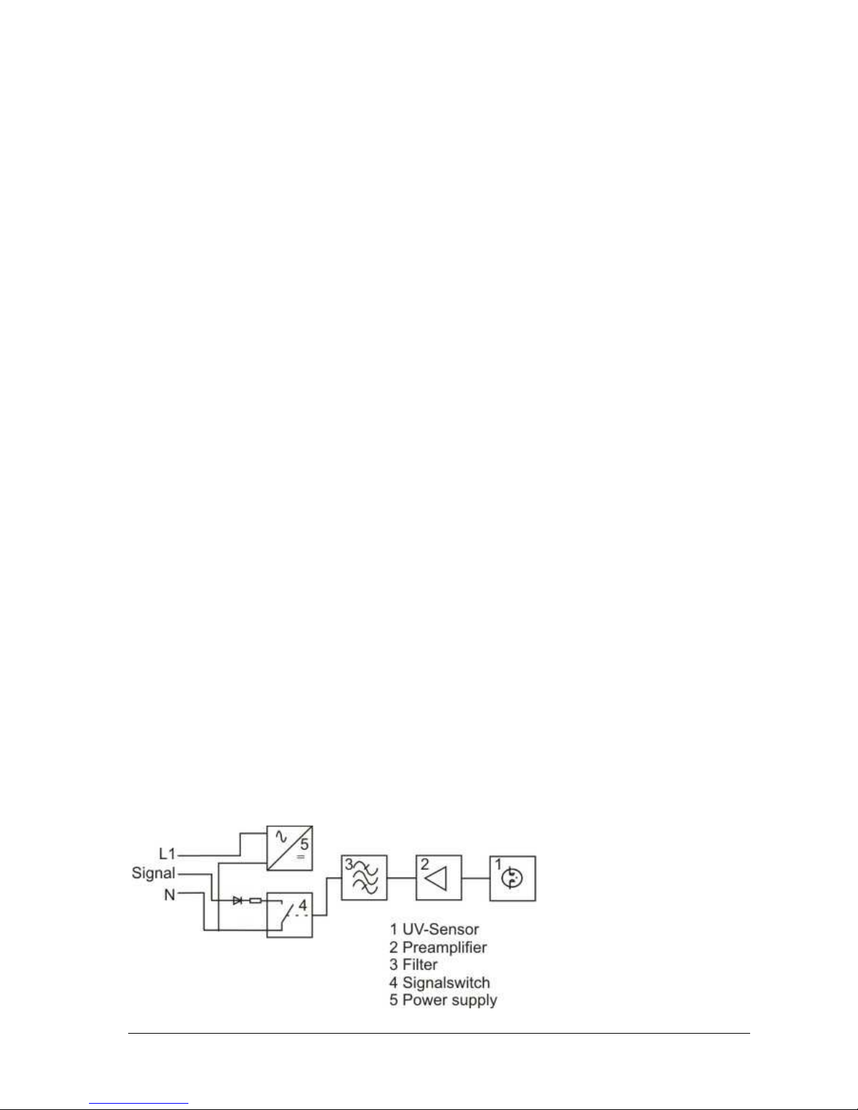
UV -
flame detector KLC 10
dual fuel burners
for
Description
The KLC 10 is a co
mpact UV flame detector, which h
combustion which produces
little
modulation/flicker frequency.
The
no
t react to background radiation from hot refractory or
The flame detector is equipped with an optical interface
intensity. The KLC 10 can
be
It is compatible in its
physical dimensions and
detectors. All KLC
accessories are identical
components used
in production and
The flame detector KLC 10
Standards EN298:2012-11
for
after
normal burner shut down when the
(formerly known as KLC 1000)
for oil -, gas- and
intermittent
burner operations
as been
developed f
light or radiation in the visible spectrum
and has
The
design of the UV sensor
ensures that the
from any other infra
which visibly
indicate
connected
directly to the ionisation or LDR input of the control box.
connection capability
to other series KLC flame
and therefore this
reduce
makes it simpler for field application and
has been developed to meet the requirements of European
burner management control units which
make a ‘no
flame amplifier is permanently
energised.
TB_KLC10_EN_REV0.DOCX
or single flame
very low flame
flame detector does
-red light source.
s the flame signal
s the variety of
service.
-flame’ check
0085
- 2 -
TB_KLC10_EN_REV0.DOCX
Safety Instruction
The KLC 10 is a safety component, and repair or adjustment must never be attempted. Replacement of
the flame detector is recommended in all cases of damage, due to impact shock, excessive moisture, or
other problems rendering it inoperable. Repair work must never be attempted and is strictly forbidden by
the relevant European Standards.
Prior to commissioning the unit; please carefully check that the wiring connections have been
made correctly. Also, before removing or checking the flame detector please ensure the power
supply is switched-off.
Technical Data
Input: AC 230 V ~ (-15/+10 %)
Frequency 50 – 60 Hz
Consumption 5, 5 mA
FET-Output: Switch-On delay after Flame-On typically 0, 5 sec.
Switch-Off time after Flame-Off < 0, 5 sec.
max. switched current 15 mA
max. switched power 0,3 W
max. switched voltage 280V AC / 400 V DC
Optical Features: Spectral range 185 – 260 nm
Acceptable loss of flame signal ca. 200 ms
Adjustment: radial, left
optional axial (reduced sensitivity at approx. 40%)
Lifetime of the UV-tube: > 10.000 h
Operating Temperature: -20ºC to +60°C (temperatures >50°C reduces the lifetime of the UV-tube)
Humidity max. 95%, no condensation permitted
Operating position: Any position
Kind of protection: IP 41
Protection Class: II
Protection against
Electric shock: DIN/EN 60730-2-5
Weight: 0,028 kg
Max’m length of
connection cable: 1 m (options available for longer cables)
Certification: CE-0085BS0448
Block diagram

- 3 -
TB_KLC10_EN_REV0.DOCX
Mounting instructions
The KLC 10 should be mounted as close as practical to the flame and on the same axis. The flame
detector is compact and should be mounted with the KLC mounting flange or other suitable holder having
a 14mm Ø opening. Fix the detector in the holder taking care to protect the sensor from other light
sources.
To avoid any problems at start-up; please avoid alignment of the KLC detector with the ignition spark
electrode as the flame detector may react with the ignition spark and cause burner shut-down during the
air pre-purge/ignition start-up sequence. The maximum length of the connection cable must be in
accordance with the technical data. Please ensure that the flame detector connection cable is kept well
apart and is completely separated from high-energy igniters- and power cables to avoid electrical
interference problems.
Attention: For safety reasons and within the technical regulations, a controlled burner shut-down of
the burner must occur and be guaranteed to happen at least once in every 24 hours of
operation. With the Model KLC 10 it is mandatory that the Control Box Unit or Burner
Management System is of the type which performs a flame check for ‘no flame presence’
on burner shut down. Such that both the burner is checked for possible ‘after burn’ and
that the UV tube itself is checked for soundness in accordance with the European
Standard EN298:2012-11. The Model KLC 10 can only be used with intermittent Control
Units which perform this flame check on shut-down. Otherwise use the model KLC 11.
If you are unsure about any application using this flame detector, please email, or fax the manufacturers
or the authorised distributor.
Mounting flange KLC
The mounting flange allows the detector to be
held and adjusted in a suitable position to view
the flame. Two overall widths of 7mm and 13mm
are available. An O-ring seal is available which
will give the mounting flange an air tight seal to
the burner housing if required.
Adapter ADP
The adapter ADP enables to install
the flame detector series KLC10 with
optional axial direction directly at a
combustion chamber. A quartz glass
serves as a barrier and prevents the
flow of heating gas from the
combustion chamber. For the use of
flame detector KLC at high ambient temperatures, a variant model of heat-insulating materials
reduces the transition temperature.
ADP 1 0 - UV
glass type
UV = quartz glass
thread
0 = NPSM ½“-14
1 = R ½“
material
1 = aluminum
2 = heat-insulating material
series
ADP = Adapter KLC

- 4 -
TB_KLC10_EN_REV0.DOCX
13,5
Dimensions
115
50 55
all dimensions in mm
Connector Diagram KLC 10
Dungs Control Box
Type of control box
MPA 22
Blue terminal no.:
12 – 5 N
Black terminal no.:
12 – 3 Ion
Brown terminal no.:
6 – 17 L1
Please ask for connection details for all other types/manufacturers burner control boxes.
Operating Indicator LED
The flame detector KLC 10 indicates the following operating conditions and flame signal strengths via the
built-in LED.
LED is OFF: KLC is not switched on – no power supply or ‘no flame’ is detected
LED is FLASHING: KLC has detected a flame; the quality of the flame signal is indicated by the
intensity of the flashing of the LED – fast flashing indicates a healthy flame signal
and vice versa - slow flashing indicates a weak flame signal.
LED is ON: KLC has detected the strongest level of flame signal.
LED
30
22
31
Radial
view opening

- 5 -
TB_KLC10_EN_REV0.DOCX
Commissioning and Maintenance
The installation and commissioning must be done by qualified personnel only. Before energising the KLC
flame detector please check the cable and wiring connections are in accordance to the diagram and
instructions given above. For good maintenance which will ensure trouble free operation of the KLC flame
detector; please keep the sight glass clean by wiping with a soft dry clean cloth. Warning: Do not use any
kind of cleaning sprays or fluids.
During commissioning and after any cleaning maintenance, the flame detector should be checked, as the
UV tube is subject to a natural ageing process and towards the end of its life span it is prone to
malfunction. To check that the flame detector is sound we recommend the following procedures be
followed:-
• Start the burner with the fuel supply closed-off or remove the flame detector from its mounting
flange and cover the UV tube using a soft cloth to avoid touching the glass lens. The control box
will lock-out at the end of the safety time due to absence of a flame signal.
• Remove the flame detector from its mounting flange. Start the burner while exposing the flame
detector to an external UV radiation source such as a cigarette lighter flame, or a small gas flame
(n.b. electric room lighting or a torch is inadequate). The burner Control Box must go to lock-out
due to detecting an extraneous light source either immediately or at the end of the air pre-purge
cycle, depending on the type/model of the Control Box.
• Close off the fuel supply or remove flame detector from its mounting flange and cover the UV tube
using a soft cloth when the burner is in the "run" position. The control box must go immediately to
lock-out resulting in the burner shutting down.
If any of these safety checks do not function as described i.e. they should always result in burner
shutdown and control box lock-out; then it is essential to replace the flame detector with a new KLC flame
detector. For safety and trouble free burner operation, we recommend that the flame detector should be
replaced after every 10,000 hours of burner operation or approximately every 30months for a burner
operating on an average of 10 hours per day.

Overview of
UV flame detectors and ancillary
Article
Flame detector KLC 10/230
Flame detector KLC 10/230,
with high sensitivity
Flame detector KLC 10/230
Flame detector KLC 10/230,
with high sensitivity
Mounting flange KLC
Mounting flange KLC
ADP 11 – UV*
ADP 21 – UV*
Connecting cable KLC
Connecting cable KLC
Connecting cable KLC
Connecting cable KLC
Connecting cable KLC
Connecting cable KLC
* only for flame detector with an axial orientation
**(reduced sensitivity at approx. 40%)
IMPORTANT:
For safety reasons and within the technical regulations, a controlled burner shut
the burner must occur and be guaranteed to happen at least once in every 24 hours of operation. With
the model KLC 10
it is mandatory that the Control Bo
type which performs a flame check for ‘no flame presence’ on burner shut down. Such that both the
burner is checked for possible ‘after burn’ and that the UV tube itself is checked for soundness in
accordance wi
th the European Standard EN298. The
Control Units which perform this flame check on shut
If you are unsure about any application using this flame detector, please
or the authorised distributor.
Disposal information
The flame detector is equipped with electrical and electronic components and
must be disposed separately
from household waste
authority regulations for
electrical component
BST Solutions GmbH
Eggerscheidter Straße 57
D - 40883 Ratingen
Telefon: +49 (02102) 1005959
Telefax: +49 (02102) 1005979
Email: info@bst-solutions.de
http://www.bst-solutions.de
©
BST Solutions 2015
DIN EN ISO 9001:2000
- 6 -
components available:
Version
optical direction radial
optical direction radial
optical direction radial and axial**
optical direction radial and axial**
overall height 7 mm
overall height 13 mm
Aluminum, R ½“, quartz glass
heat-insulated up to 180°C,
R ½“, quartz glass
length of 300mm
length of 350mm
length of 600mm
length of 1000mm
length of 2000mm
special lengths on request
x Unit or Burner Management System is of the
model KLC 10
can only be used with intermittent
-down. Otherwise use the
email, or fax the manufacturers
. Please follow your local
waste disposal.
technical modifications reserved
TB_KLC10_EN_REV0.DOCX
Part-No.
611145021000
611145021160
611145061000
611145061160
665001010000
665002010000
575010512210
575010512230
661030040100
661035040100
661060040100
661100040100
661200040100
-down of
model KLC 11.
Revision 0
 Loading...