


BST Web Guiding System
ekrPro Com60
with analog sensors
BST International GmbH
Heidsieker Heide 53
33739 Bielefeld, Germany
Tel: +49 5206/999-0
Fax: +49 5206/999-999
e-mail: info@bst-international.com
ekrPro Com
with analog sensors Date: 23.11.2007
60
web guide controller EDV-No.: MD.191.01.05/1.6.x
Symbols used in this operating manual
Warning signs
Symbols are used in this operating manual in order to clearly
indicate particularly important places.
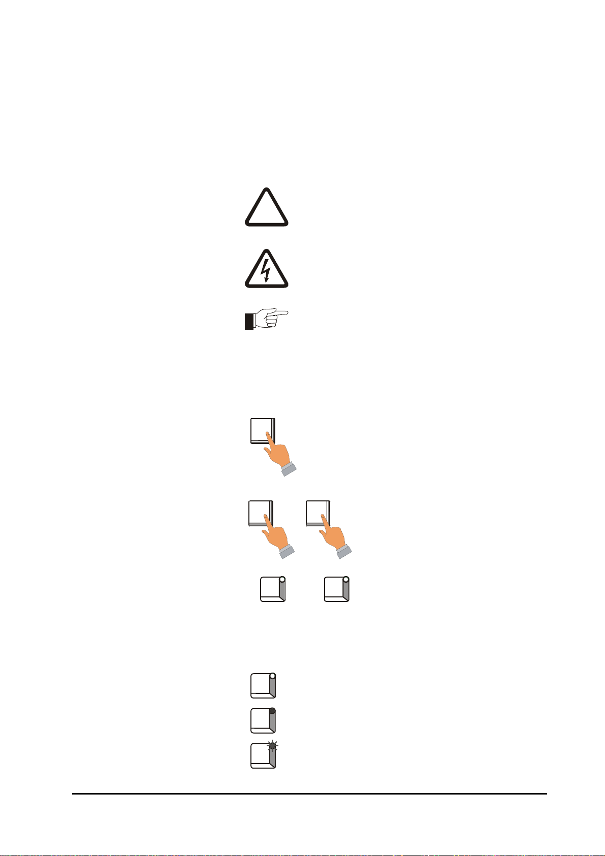
Attention!
!
Using the keys
Using the keys is represented by the following symbols in this
manual:
You must obey this type of warning, in order to protect
yourself, as the operator, from bodily injuries arising
from mechanical movements.
Beware!
You must obey by this type of warning without fail, in
order to protect yourself, as the operator, from life
threatening injuries caused by electrical voltages.
Note
This symbol is used to point out additional useful tips,
which will help you to make optimum use of all of the
functions.
Press key.
LED operating status
indications
+
1) 2)
Some keys on the front panel of the ekrPro Com60 controller have
LED´s (light-emitting diodes) integrated in them. The different LED
operating states are represented as follows:
LED off
LED constantly lit = activated phase
LED flashing
Key combinations, keys have to be
pressed simultaneously.
Press keys in the specified order.
ekrPro Com
with analog sensors Date: 23.11.2007
60
web guide controller EDV No.: MD.191.01.05/1.6.x

Contents
Symbols used in this operating manual
Table of contents
Section A General information
Section B Commissioning
Section C Operation
Section D Appendix
ekrPro Com
with analog sensors Date: 23.11.2007
60
web guide controller EDV No.: MD.191.01.05/1.6.x
ekrPro Com60
with analog sensors
Section A
General information
A 1 Description
A 2 Specifications
A 3 Transport / Storage
A 4 Decommissioning
ekrPro Com
with analog sensors Date: 23.11.2007
60
web guide controller EDV No.: MD.191.01.05/1.6.x

Contents
Section A
General information
Symbols used in this manual
Table of contents
A 1 Description A1-1
A 1.1 General information A1-1
A 1.2 Utilisation A1-1
A 1.3 Housing versions A1-1
A 1.4 General definitions A1-2
A 1.4.1 Assignment of sensors to the guiding mode A1-2
selection keys
A 1.4.2 Inverting of the sensor signal A1-3
A 1.4.2 Size of oscillation amplitude related to sensor
scanning area A1-3
A 1.4.2 Oscillation types and curves A1-4
A 1.4.2 Allocation of FVGs for a FVGPro 2MK A1-4
A 1.5 Connectable components A1-4
A 1.6 Safety information A1-5
A 1.7 Emissions A1-5
A 2 Specifications A2-1
A 2.1 ekrPro Com
A 2.2 Optical edge sensor IR2001, IR2005 A2-3
A 2.3 Optical edge sensor IR2002 A2-3
A 2.4 IRS-U-2 A opto-electronic analog sensor A2-3
A 2.5 Ultrasonic edge sensor US2003, US2007, US2008 A2-4
A 2.6 Reflecting sensor TW 54 C 5 A2-4
A 2.7 Line sensor T 62 D 1 A2-5
A 2.8 Reflected light measuring light barrier R 42 D ... A2-5
A 2.9 Photoelectric fork sensor G 53 C2/5 A2-6
A 2.10 Switched power pack A2-7
A 3 Transport / Storage A3-1
A 4 Decommissioning A4-1
60
controller (version XT) A2-1
ekrPro Com
with analog sensors Date: 23.11.2007 Page: 1/1
60
web guide controller EDV No.: MD.191.01.05/1.6.x

Description A 1
The start-up, maintenance and installation
!
instructions described in this operating manual
must be strictly adhered to!
A 1 Description
The aim of the operating manual is to enable you to use the
guiding system rapidly by explaining the basic settings for initial
start-up (start-up menu) and the conventional functions for
operation. In addition, the complex functions will be described
using selected examples for setting certain parameters.
A 1.1 General information
This family of control systems includes:
• ekrPro Com
• ekrPro Key
Devices in the controller family can be interconnected at different
levels into a system network via a CAN-Bus.
A 1.2 Utilisation
The ekrPro Com
controller. Together with other BST components it may be used for:
• Web edge guiding (right or left)
60
: Controller with keyboard
60
: External control keyboard.
60
is a microprocessor controlled web guiding
A 1.3 Housing Versions
• Web center guiding
• Guiding on continuous or interrupted printed lines
• Guiding on continuous or interrupted printed edges (still
being prepared)
• Web width measuring
The controller includes a separate control unit that can directly
control the sensor adjustment unit and it can be interconnected into
the system.
Any other utilisation must first be authorised by the manufacturer.
There are also standard PLC compatible inputs and outputs as well
as an OK-reporting system present.
The control unit ekrPro Com
60
is available in two different housing
versions:
• ekrPro Com60 XT: Mounting unit
(e.g. for wall mounting)
60
• ekrPro Key
Desk XT: Built-in unit
(e.g. for insertion in a
control console)
ekrPro Com
60
web guide controller
EDV No.: MD.191.01.05/1.6.x Chapter: A 1
with analog sensors Date: 23.11.2007 Page: 1/5
Description A 1
A 1.4 General
Settings
A 1.4.1 Assignment of sensors to the
to the scanning mode selection keys
In this operating manual, the edge sensors that are connected to
the controller are designated with “sensor 1” and “sensor 2”. On
the operating keyboard of the controller, the guiding mode
selection keys have the lettering „SENSOR LEFT“ and „SENSOR
RIGHT“ respectively.
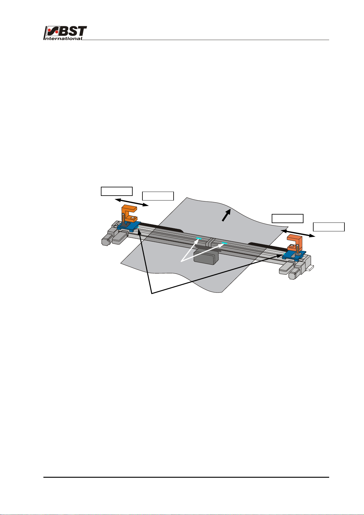
According to the BST definition, the following link applies:
SENSOR LEFT = Sensor 1
SENSOR RIGHT = Sensor 2
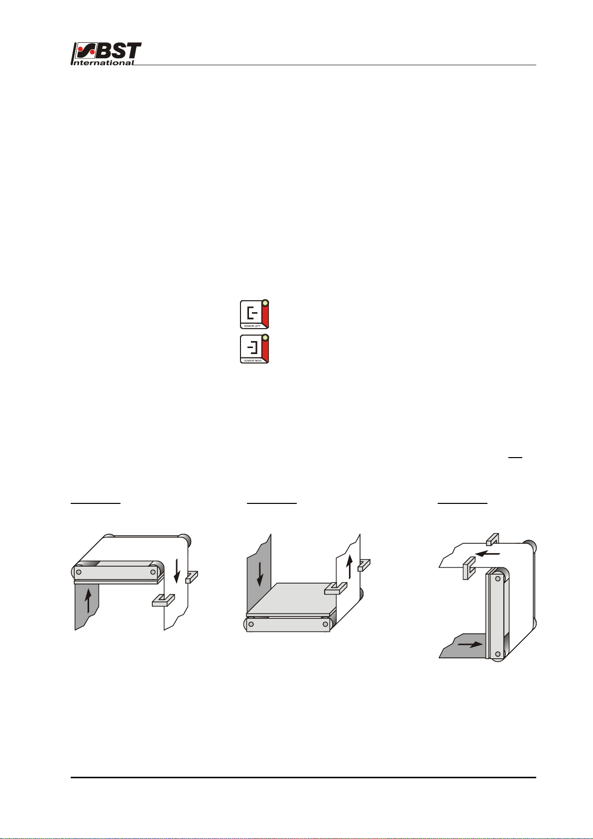
The following is valid in respect of the sensor mounting positions:
The sensor, which is located to the left of the material in the
web movement direction (when looking from the material top
side), is sensor 1.
Example 1:
The material top side is the side of the material web which is not
direct contact with the deflection pulleys of the pivoting frame.
Example 2: Example 3:
Sensor right
(Sensor 2)
Sensor left
(Sensor 1)
Sensor left
(Sensor 1)
Sensor right
(Sensor 2)
Sensor left
(Sensor 1)
As standard, sensor 1 (Sensor left) must be connected to
connector X50 (terminal X1), while sensor 2 (Sensor right) must be
connected to connector X51 (terminal X2) of the terminal board.
Sensor right
(Sensor 2)
in
ekrPro Com
60
web guide controller
EDV No.: MD.191.01.05/1.6.x Chapter: A 1
with analog sensors Date: 23.11.2007 Page: 2/5
Description A 1
A 1.4.2 Inverting of the
sensor signal
If a BST edge sensor, of typical C-design, is mounted according to
the BST definition (see section A 1.4.1) as "Sensor left" (sensor 1),
then no inversion of the sensor signal is necessary.
If a BST edge sensor is mounted according to the BST definition
as "Sensor right" (sensor 2), then inversion should be activated via
the setup menu (see section B 3.4.4.3.1).
When the control units is delivered, inversion of the
sensor signal for sensor 2 is activated (factory setting).
Sensor left
Not permitted:
► Sensor:
Invert!
(Sensor looks to the left in the
direction of travel.)
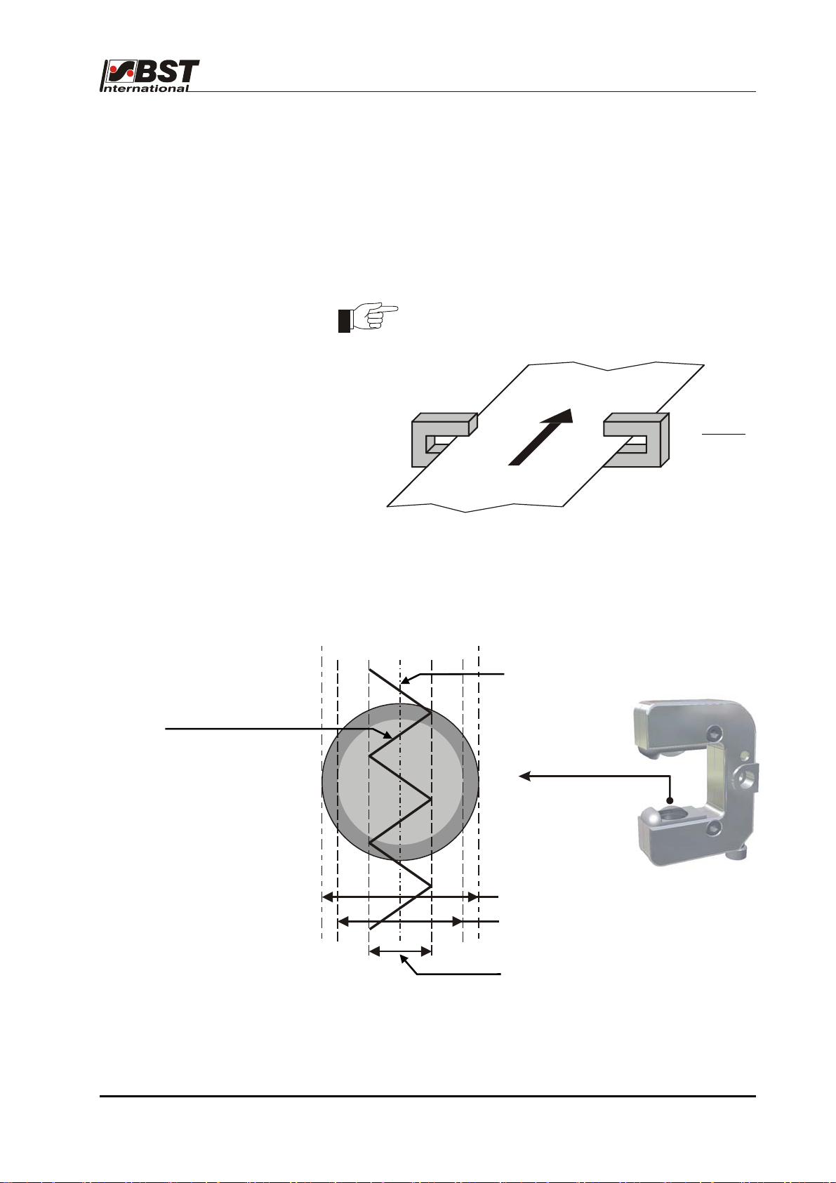
A 1.4.3 Size of oscillation amplitude
related to sensor scanning area
0 %
30 %
70 %
100 % Sensor coverage
Centre of sensor scanning area (visual range).
Oscillating web position
100 % of the sensor visual range
80 % of the sensor visual range =
maximum oscillation amplitude
40 % of the sensor visual range
The maximum possible oscillation amplitude is 80% of the sensor
visual range.
As an example, the oscillating web position is shown herewith an
attitude of 40% in "Sensor oscillation" mode.
ekrPro Com
60
web guide controller
EDV No.: MD.191.01.05/1.6.x Chapter: A 1
with analog sensors Date: 23.11.2007 Page: 3/5
Description A 1
A 1.4.4 Oscillation types and curves
An oscillation can be implemented either as a sensor oscillation or
an FVG oscillation.
In the case of the sensor oscillation, the curve described is a delta
function.
The FVG oscillation describes a curve in accordance with a sine
function.
Selections and settings are described under Point B 3.7.5.8.2.
A 1.4.5 Allocation of FVGs for a FVGPro 2MK
Traverse the FVG using the
appropriate key in the menu window
<<< >>>
FVG 1
>>> <<<
internal
limit switch
external
limit switch
Web travel direction
>>> <<<
<<< >>>
FVG 2
A 1.5 Connectable
components
The general plan (annex C2) shows the components that can be
connected to the ekrPro Com
60
controller.
60
ekrPro Com
with analog sensors Date: 23.11.2007 Page: 4/5
web guide controller
EDV No.: MD.191.01.05/1.6.x Chapter: A 1
Description A 1
A 1.6 Safety information
The safety relevant information in accordance with DIN EN 294,
DIN EN 349 and the industry specific safety regulations must be
taken into consideration when installing the BST equipment in the
production machine, these include:
• There must be a safe distance between the BST equipment and
the machinery already installed on-site, such as machine
panels, building structure, etc.
• The interconnecting lines between the control equipment and the
control components or edge sensors must be laid so that nobody
can trip over them, they are not taught and they are well
anchored.
• Ensure that there is sufficient free headroom.
If the free passage is restricted, the relevant building
components causing the restrictions must be padded and a
danger warning signs must be attached to them (yellow/black).
Only trained specialist personnel are permitted to
undertake the assembly, installation and
!
commissioning!
Before starting work, ensure the equipment is
electrically isolated. To this end always carry out the
following measures:
1. Switch off
2. Prevent switching back on.
3. Check the equipment is isolated.
4. Earth.
5. Cover or shield any adjacent parts that are still live.
The mains power must always be switched off before
the equipment is opened.
If it becomes necessary to work on the open equipment
with voltage applied, then only Protection class IP 20 is
provided.
There is always increased danger because of the mains
!
!
• Any transport safety devices that were used must be removed
prior to commissioning.
voltage!
Do not use the chassis or machine frame as a climbing
aid or a stepladder.
Do not remove any of the safety devices.
Positioning movements will be undertaken by the
actuator during functional testing away from the
production machine and/or during the commissioning!
The relevant safety arrangements must implemented
during performance checks!
Monitor the overall safety concept of the production
machine during commissioning!
A 1.7 Emissions
The A-rated equivalent continuous sound level of the equipment is
less than 70 dB(A).
60
ekrPro Com
with analog sensors Date: 23.11.2007 Page: 5/5
web guide controller
EDV No.: MD.191.01.05/1.6.x Chapter: A 1

Specifications A 2
A 2 Specifications
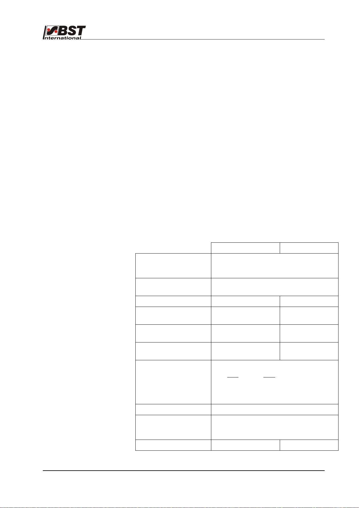
A 2.1 ekrPro Com
Power supply 24V DC ± 5%
Power consumption 4W (without motor)
Input capacitance approx. 950µF
Controller inputs 2 x sensors, -9,75 V ...+9,75 V oder 0 V ...+9,75 V
FVG inputs 1x blocking, no
Digital inputs 12x digital inputs, no
Power supply outputs 2 x 24V (for CCD Pro camera)
60
controller (version XT)
12 bit selectable via software.
1 x sensor, -10,3 V to +10,3 V, 12 bit
1x EFE pot, -10,3 V to +10,3 V, 12 bit
1x pot return, -10,3 V to +10,3 V, 12 bit
1 x tacho, -9,0 V to + 9,0 V
1x blocking, input resistor 4.7 KΩ, operating points (<4 V (low)
and >8 V (high)), but can only be used against “+“ switched
sensors (pnp)
2x reference switch, no metallic separation
input resistor 4.7 KΩ,
operating points (<4 V (low) and >8 V (high)),
but can only be used against “+“ switched sensors (pnp),
supply 24V DC
input resistor 4.7 KΩ,
operating points (<4 V (low) and >8 V (high)),
but can only be used against “+“ switched sensors (pnp),
supply 24V DC
metallic separation
metallic separation,
Controller outputs Controller outputs -10.3V to -10 V, 12 bit 1x analog output
-10 V to +10 V, 2 mA
2x IR pulses
1x lamp supply 5 V, 1 A
Digital outputs 4 x digital outputs +24V, 1.0A per output, 1.5A
in total
No metallic separation.
Protected against feedback (positive voltage)
Controller output stage 1x DC motor 24V DC, max. 3 A, short circuit protected.
Select voltage, current or tachometer control (in preparation)
PWM 20 kHz
FVG output stage 1 x stepping motor, max. 1.5A; not
short circuit protected
CAN-bus 1x plug, 1x socket; no metallic separation
Screw connections /
plugs
Variable through exchangeable connection plate;
see Appendix D6
Protection class IP 54
60
ekrPro Com
web guide controller EDV No.: MD.191.01.05/1.6.x Chapter: A 2
with analog sensors Date: 23.11.2007 Page: 1/7
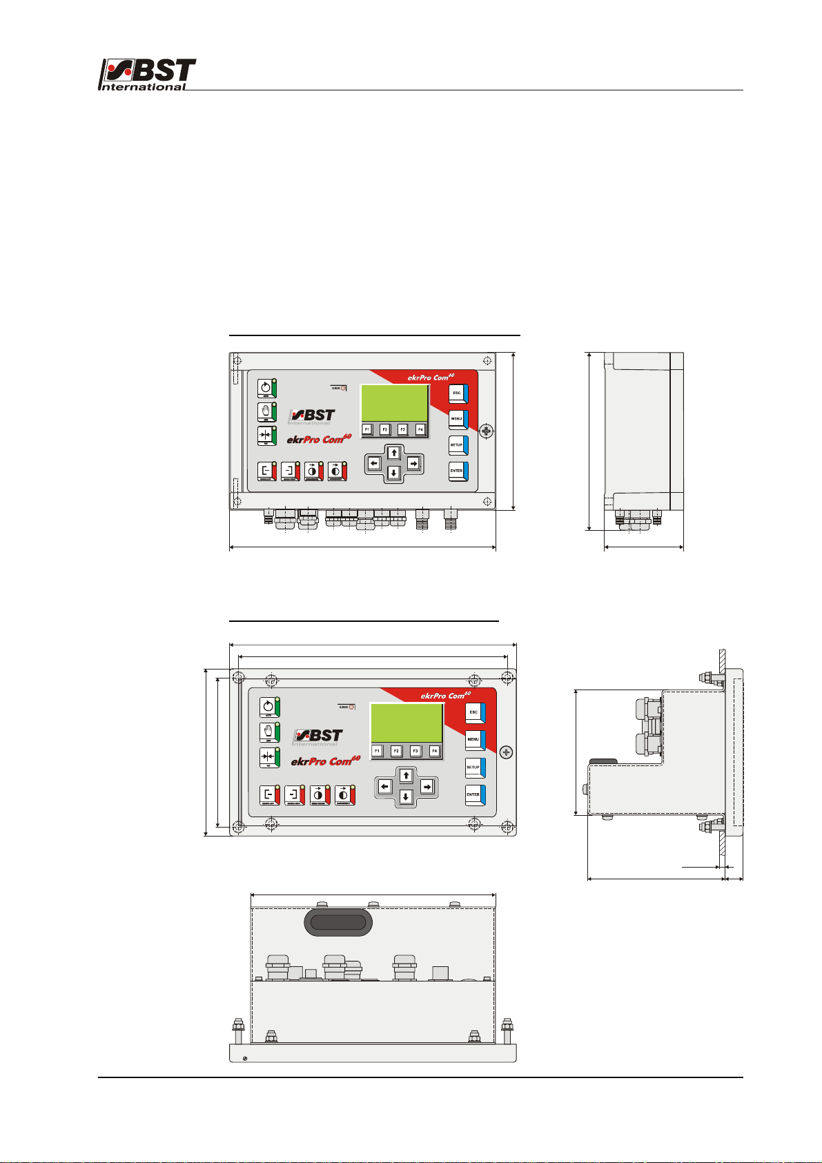
Specifications A 2
240
140
Display: LCD graphics module with 128 x 64 pixel and LED
background illumination
Ambient conditions: Temperature: 0° to 45°C max.
Humidity: 5% - 90%,
no condensation
Weight: ekrPro Com
ekrPro Com
60
: approx. 2.1 kg
60
Desk: approx. 2.3 kg
Case dimensions ekrPro Com
60
(Mounting unit):
140
160
240
70
Installation ekrPro Com
60
Desk (Built-in unit)
225
125
105
205
max. 10
15115
60
ekrPro Com
web guide controller EDV No.: MD.191.01.05/1.6.x Chapter: A 2
with analog sensors Date: 23.11.2007 Page: 2/7

Specifications A 2
A 2.2 A2.2 Optical edge sensor
IR 2001, IR 2005
Power supplies: from the controller
Measuring range, typical: 12 mm
Visual range, typical: 15 mm
Output: analog
Protection class: IP 54
Ambient conditions: Temperature: 0 to a max. 45 °C
Humidity: 5% - 90%, no condensation
Case dimensions:
(standard version)
A 2.3 Optical edge sensor
IR 2002
Power supplies: from the controller
Measuring range, typical: 8 mm
Visual range, typical: 13 mm
Output: analog
Protection class: IP 54
Ambient conditions: Temperature: 0° to 45°C max.
Case dimensions:
(standard version)
A 2.4 IRS-U-2 A opto-electronic analog sensor
See the manufacturer’s data-sheet
W = 40 mm
H = 95 mm
D = 107 mm
Humidity: 5% - 90%, no condensation
W = 25 mm
H = 57 mm
D = 85.5 mm
60
ekrPro Com
with analog sensors Date: 23.11.2007 Page: 3/7
web guide controller EDV No.: MD.191.01.05/1.6.x Chapter: A 2

Specifications A 2
A 2.5 Ultra-sonic sensor
US2003, US2007,
US2008
Power supplies: from the controller
Measuring range, typical: 15 mm (US 2008 = 4 mm)
Visual range, typical: 15 mm (US 2008 = 6 mm)
Output: analog
Protection class: IP 54
Ambient conditions: Temperature: 0 to a max. 45 °C
Humidity: 5% - 90%, no condensation
A 2.6 Reflection button
TW 54 C5
Case dimensions:
(standard version)
Power supplies: 8V – 15V; from the controller
Lamp voltage: 5V; 0.8A; from the controller for:
Measuring range: 5.0 mm at 6 mm sensing distance
Output signal: Negative with black areas
Protection class: IP 65
Ambient conditions: Temperature: 0 to a max. 50 °C
Weight: 240 g
Case dimensions: W = 26 mm
B= 25 mm
H = 76 mm
D = 113 mm
maximum of one sensor
2.5 mm at 13 mm sensing distance
Positive with white areas
Humidity: 5% - 90%, no condensation
H = 54.5 mm
D = 85.5 mm
60
ekrPro Com
with analog sensors Date: 23.11.2007 Page: 4/7
web guide controller EDV No.: MD.191.01.05/1.6.x Chapter: A 2
Specifications A 2
A 2.7 Line sensor T 62 D 1
Power supplies: from the controller
Lamp voltage: 5 V; 0.8 A
Sensing distance: 15 -30 mm
Measuring range: 3 -8 mm
Line widths: 0.5 -5 mm
Output voltage: 0 to ±10V
Protection class: IP 65
Ambient conditions: Temperature: 0 to a max. 50 °C
Humidity: 5% - 90%, no condensation
Weight: 1,100 g
Case dimensions: B= 67 mm
H = 105 mm
D = 128 mm
A 2.8 Reflected light
measuring light barrier R 42 D, etc.
R 42 D 12 R 42 D 16
Power supplies: +12V, 12 mA or
±12V, 15 mA or
±15V, 20 mA
Lamp voltage: 5V, 4W; from the controller for a maximum of
one sensor
Max. distance: 1 m 2 m
Measuring range
15 mm 40 mm
in front of front lens:
Diameter of light beam
25 mm 55 mm
in front of front lens:
Diameter of light beam
40 mm 55 mm
at half distance
Output voltage:
at: U
= +12 V
B
U
= ±12 V
B
U
= ±15 V
B
Corresponding to change in illumination:
dark
light
8.5V 2V
8.5V 0V
10.5V 0V
Protection class: IP 65
Ambient conditions: Temperature: 0° – 70°C
(temperature compensation
only up to 50°C
Weight: 1,000 g 1,200 g
60
ekrPro Com
web guide controller EDV No.: MD.191.01.05/1.6.x Chapter: A 2
with analog sensors Date: 23.11.2007 Page: 5/7

Specifications A 2
A 2.9 Fork light barrier
G 53 C2/5
Power supplies: from the controller
Lamp voltage: 5V
Fork width: 29 mm
Measuring range: ± 3.5 mm
Diameter of light beam: 11 mm
Protection class: IP 65
Ambient conditions: Temperature: -20 to a max. 60 °C
Humidity: 5% - 90%, no condensation
Weight: 400 g
Case dimensions: B= 21 mm
H = 85 mm
D = 87 mm
60
ekrPro Com
with analog sensors Date: 23.11.2007 Page: 6/7
web guide controller EDV No.: MD.191.01.05/1.6.x Chapter: A 2

Specifications A 2
A 2.10 Switched power pack
Supply of the ekrPro Com
60
including the BST components takes
place over the switched power pack.
There are two supply possibilities:
1. over a central power pack in the machine
2. over a power pack allocated to the BST part
The following details are based on a control system comprising a
control unit ekrPro Com
60
, analogue sensors, sensor adjustment
unit and actuator (EMS1, EMS5, EMS10, EMS16, EMS17 or
EMS20)
1. Central supply
If supply takes place centrally from the machine the following
parameters are to be fulfilled:
• Output voltage: 24 V DC ± 5%
• Output current: 4.2 A DC
• Output power: 100 W
The power pack must be able to quickly charge (~ 5 sec) the input
capacitance (approx. 950µF) of the control amplifier after switching
on without recognizing this as a short circuit and so switching off
again.
The output should be permanently resistant to short-circuiting,
overloading and idle running.
2. Separate power pack
If a separate power pack is used for the BST components, we
recommend the use of units manufactured by PULS GmbH:
Input voltage: 85 - 264 V AC or 220 – 375 V DC
Output voltage: 24 V DC ± 5%
Output current: 4.2 A DC
Output power: 100 W
BST order number: 103 837
If a number of control systems are to be supplied from a single
switched power pack, then, dependent on the total required power,
the following power packs are also available:
Input voltage
85 – 264 V AC
220 -700 V DC
85 – 264 V AC
220 -700 V DC
340 – 479 V AC /3Ph.
450 -700 V DC
Output
voltage
24 V DC ± 5 % 10 A DC 240 W 118 661
24 V DC ± 5 % 20 A DC 480 W 109 365
24 V DC ± 5 % 20 A DC 480 W 116 679
Output
current
Output
power
BST order
number
60
ekrPro Com
web guide controller EDV No.: MD.191.01.05/1.6.x Chapter: A 2
with analog sensors Date: 23.11.2007 Page: 7/7

Transport A 3
A 3 Transport
The equipment will be shipped in accordance with the details
stipulated in the order:
• completely assembled and interconnected to the web guide
control system
• as component parts in standard cardboard boxes with cellular
lining material
If the unit will not be incorporated immediately, it should be stored
in a dry room until installation.
60
ekrPro Com
with analog sensors Date: 23.11.2007 Page: 1/1
web guide controller EDV No.: MD.191.01.05/1.6.x Chapter: A 3

Decommissioning A 4
A 4 Decommissioning
Decommissioning (scraping) the systems must be carried out in
together with the entire machine.
The necessary procedures must be prepared by the manufacturer
of the machine. You must take into consideration that the control
system is generally considered to be an electrical / electronic
device, which must be disposed of in accordance with the current
legal requirements.
You might also be able to return the system to BST International
GmbH, but the corresponding agreement must be made first.
ekrPro Com
60
web guide controller
EDV No.: MD.191.01.05/1.6.x Chapter: A 4
with analog sensors Date: 23.11.2007 Page: 1/1

ekrPro Com60
with analog sensors
Section B
Commissioning
B 1 Installation
B 2 Controls
B 3 Commissioning
B 4 Terminal assignments and service displays
ekrPro Com
with analog sensors Date: 23.11.2007
60
web guide controller EDV No.: MD.191.01.05/1.6.x

Contents
Section B
Commissioning
Symbols used in this manual
Table of contents
B 1 Installation B1-1
B 1.1 Installation site requirements B1-1
B 1.2 Installation ekrPro Com
B 1.2.1 Securing hole diagram B1-1
B 1.2.2 Installation B1-1
B 1.3 Installation ekrPro Com
B 1.3.1 Installation dimensions B1-2
B 1.3.2 Cabling B1-2
B 1.3.3 Installation B1-3
B 1.4 Installation instructions for EMC-wiring B1-4
B 1.5 Installation contrast/line sensor B1-5
B 1.5.1 Sensor arrangement B1-5
B 1.5.2 Installation line sensor T 62 D 1 B1-6
B 1.5.3 Installation reflection sensor TW 54 C 5 B1-7
B 2 Display and operating controls B2-1
B 2.1 Control panel B2-1
B 2.2 Navigating within the system B2-2
B 2.2.1 Function keys (F-keys) B2-2
B 2.2.2 Arrow keys B2-5
B 2.2.3 Buttons B2-6
B 3 Commissioning B3-1
B 3.1 General information B3-1
B 3.2 Electrical connections B3-2
B 3.3 Commissioning with a CAN bus B3-3
B 3.3.1 Check unit address or set up if necessary B3-3
B 3.3.2 Terminator activation B3-5
B 3.4 Adjust password B3-7
B 3.5 Commissioning standard system B3-9
B 3.5.1 Select standard system B3-9
B 3.5.2 Carry out master setup B3-10
B 3.5.3 Setting the actuator guiding direction B3-11
B 3.5.4 Setting the actuator path limits B3-11
B 3.5.5 Servo centre position and amplification for the B3-12
“SC” operating mode
B 3.5.6 Carry out material setup B3-13
B 3.5.6.1 Automatic material set-up B3-14
B 3.5.6.2 Manual material set-up B3-14
B 3.5.7 FVG - Sensor positioning device B3-15
B 3.5.8 Additional Functions B3-19
B 3.5.8.1 Tear Off Detection B3-19
B 3.5.8.1 Oscillation B3-23
B 3.6 Save settings B3-25
60
(Mounting unit) B1-1
60
Desk (Built-in unit) B1-2
ekrPro Com
60
web guide controller EDV No.: MD.191.01.05/1.6.x
with analog sensors Date: 23.11.2007 Page: 1/2

B 3.7 Set-up menu B3-26
B 3.7.1 Change User - User level selection B3-26
B 3.7.2 Material Setup - Sensor compensation B3-26
B 3.7.3 Sel. Std. System - Selection of a standard system B3-26
B 3.7.4 Save/Load settings- Load or save settings B3-26
B 3.7.5 General Set-up - System parameters B3-27
B 3.6.4.1 Setting the default values B3-27
B 3.6.4.2 Actuator –Actuator settings B3-28
B 3.6.4.3 Sensors/ EF E - Com m i s si o n i ng s e n so r s a n d EF E B3-35
B 3.6.4.4 Control Loop - Control loop settings B3-37
B 3.6.4.5 FVG - Sensor positioning device B3-38
B 3.6.4.6 Width Measure - Web width measurement B3-50
B 3.6.4.7 Edge Sources - Assignment of the sensors B3-54
to the guiding modes
B 3.6.4.8 Add. Functions - Special functions B3-56
B 3.6.4.9 Dig. IO Config. - Configuration of the digital B3-60
inputs and outputs
B 3.6.4.10 Special - Special device settings B3-69
B 3.6.5 Opt. Logic - Optional logic B3-72
B 3.6.6 Fieldbus - Field bus B3-72
B 3.6.7 Remote Device - Commissioning with a CAN bus B3-73
B 3.6.8 Test - Test program for service purposes B3-74
B 4 Terminal assignments and service displays B4-1
B 4.1 Board overview B4-1
B 4.2 Terminal diagrams B4-2
B 4.3 Service indicator displays B4-9
ekrPro Com
60
web guide controller EDV No.: MD.191.01.05/1.6.x
with analog sensors Date: 23.11.2007 Page: 2/2

Installation B 1
22
B 1 Installation
B 1.1 Installation site requirements
The ekrPro Com
free area.
Ambient conditions: Temperature: 0 to a max. 45°C
Humidity: 5 - 90%, no condensation
B 1.2 Installation ekrPro Com
60
(mounting unit)
B 1.2.1 Securing hole diagram
Ø
6
B 1.2.2 Installation
Attention! A free area of at least 300 mm in front of the housing
must be guaranteed so that it can be opened.
60
controller must be installed in a dry, vibration-
5
ekrPro Com
60
housing
5
2
1
1. Drill the securing holes as
shown in the mounting plan.
2. Use the four
screws to attach the
housing.
3. Wire in the electric cables (if
required) or plug in the
necessary cable
connections.
securing
60
ekrPro Com
web guide controller EDV No.: MD.191.01.05/1.6.x Chapter: B 1
with analog sensors Date: 23.11.2007 Page: 1/7
Installation B 1
B 1.3 Installation
ekrPro Com60 Desk
(built-in unit)
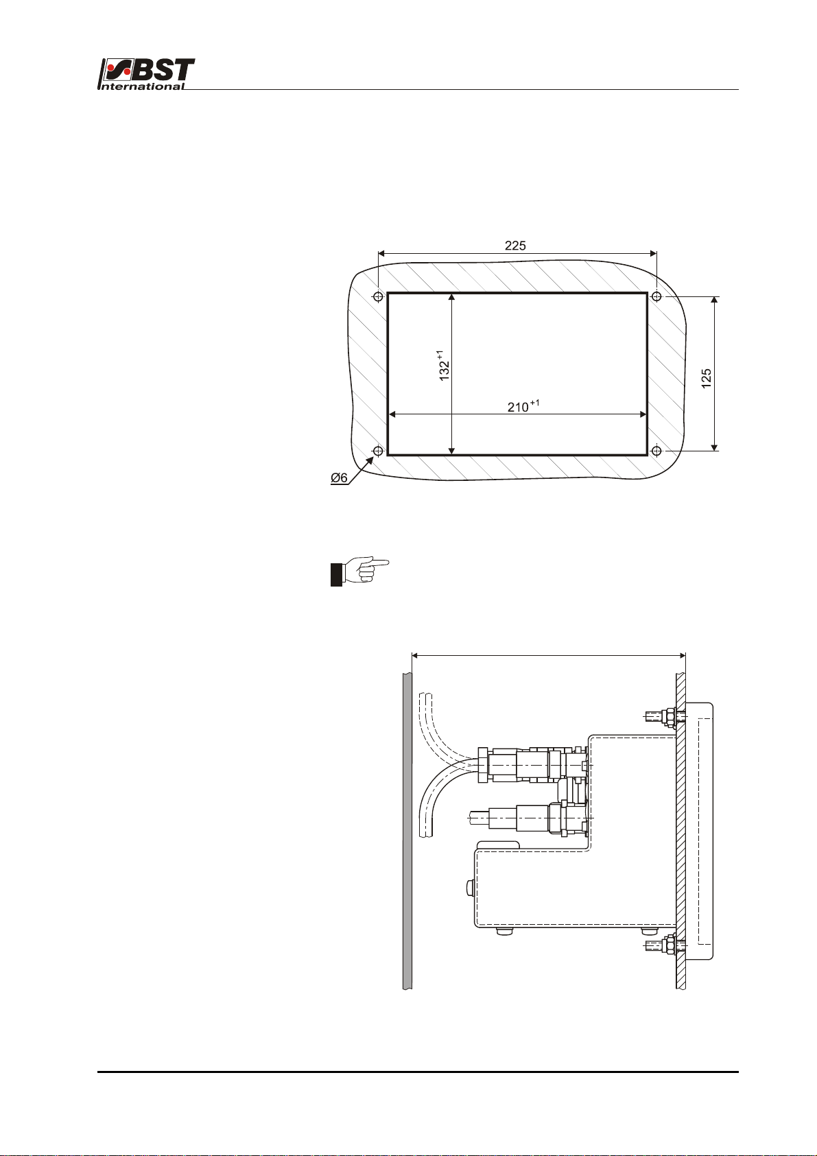
B 1.3.1 Installation dimensions
B 1.3.2 Cabling
Attention!
A space of at least 140 mm must be guaranteed for the
cabling in order to ensure that the cables are laid
correctly (see illustration).
Section
min. 140
60
ekrPro Com
with analog sensors Date: 23.11.2007 Page: 2/7
web guide controller EDV No.: MD.191.01.05/1.6.x Chapter: B 1
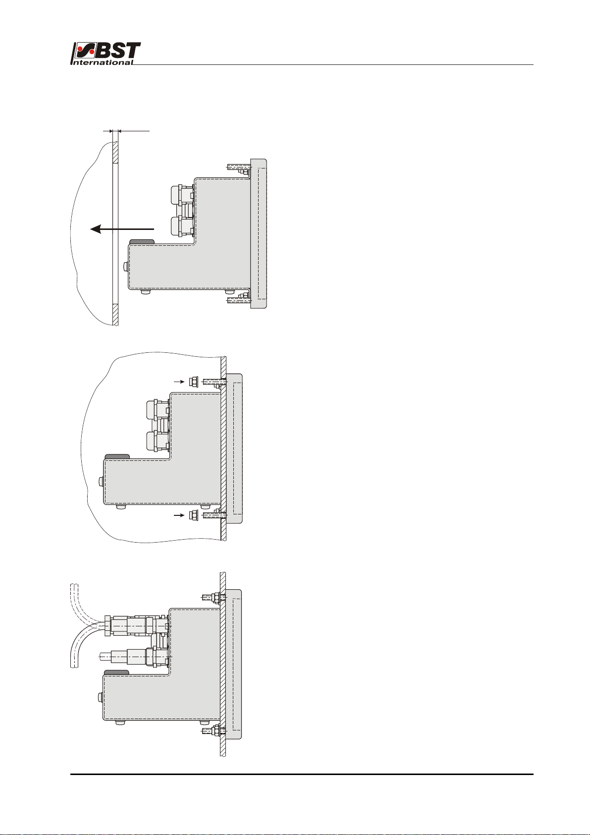
Installation B 1
B 1.3.3 Installation
max. 10
1. Cut out the insertion hole and drill four
mounting holes
(installation dimensions see chapter B 1.3.1).
2. Slide the ekrPro Com
60
Desk into the recess.
3. Use the four securing screws to secure the
controller ekrPro Com
60
Desk in place.
4. Wire in the electric cables or plug in the
necessary cable connections.
Attention!
A free area of at least 300 mm in front of the
housing must be guaranteed so that it can be
opened.
60
ekrPro Com
web guide controller EDV No.: MD.191.01.05/1.6.x Chapter: B 1
with analog sensors Date: 23.11.2007 Page: 3/7

Installation B 1
B 1.4 Installation instructions for EMC-wiring
housing wall
Union nut
Intermediate supports
Cable insert
1. Unscrew in the union nut for the cable
screw-in cable glands.
2. Pull out the clamping insert from the
intermediate supports.
Attention! Do not press down on the
cable insert.
3. Strip cable back by 8 mm so that the
screen braiding is uncovered
4. Pull the union nut onto the cable
5. Feed the cable into the cable clamp
and bend the screening back over the
cable clamp.
6. Push the clamping insert to the
intermediate support.
7. Fit the screws.
60
ekrPro Com
web guide controller EDV No.: MD.191.01.05/1.6.x Chapter: B 1
with analog sensors Date: 23.11.2007 Page: 4/7
Installation B 1
B 1.5 Installation
contrast / line sensor
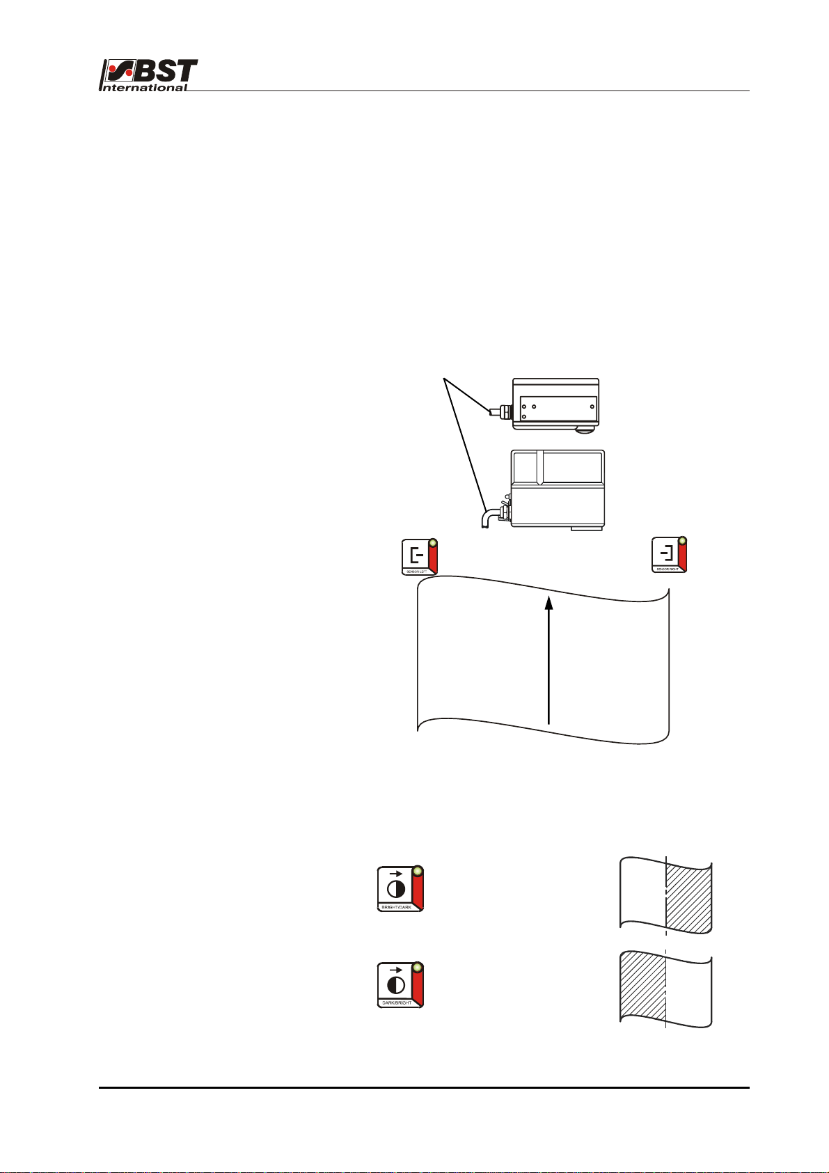
B 1.5.1 Sensor arrangement
The sensors must be arranged as follows in order to ensure clear
allocation of the two keys on the front foil of the controller to the
corresponding contrast transitions:
• The sensor connection cable points in the direction of
sensor 1.
Sensor 1
This sensor arrangement results in the following key allocation:
Connection
cable
Material web
→
→
TW 54 C 5
T 62 D 1
Sensor 2
web running direction
Contrast transition
BRIGHT/DARK
Contrast transition
DARK/BRIGHT
60
ekrPro Com
with analog sensors Date: 23.11.2007 Page: 5/7
web guide controller EDV No.: MD.191.01.05/1.6.x Chapter: B 1
Installation B 1
°5°
°
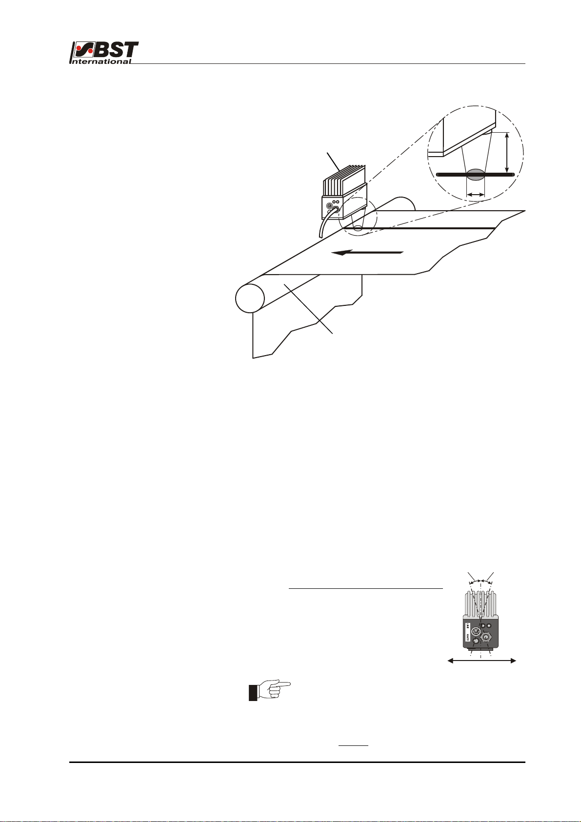
B 1.5.2 Installation
line sensor T 62 D 1
T 62 D 1
17
ø8
Deflection roller
Scanning arrangement T 62 D 1
The following points must be adhered to during installation of the
T 62 D 1 in order to realise optimum guiding results:
• The line sensor should be mounted on a torsionally rigid base.
• The line / contrast must be placed at right angles to the
longitudinal axis of the sensor (see drawing).
• The scanning should be carried out on a deflection roller.
This will ensure that any material web height fluctuations are
eliminated at the scanning point.
• The distance between the sensor scanning optics and the
material web must be set so that there is a light spot with a
diameter of approximately 8 mm (corresponding to a scanning
distance of approximately 17 mm) on the web.
• We recommend that the sensor angle is
reduced by 5° - 15° in the web running
direction when using very reflective materials
.
…15
5°…15
Web running direction
The light spot diameter can be reduced in size by
altering the distance from the web in order to
optimise the system when working with poor
contrast or narrow lines.
The scanning distance clearance must never
exceed 30 mm
.
60
ekrPro Com
web guide controller EDV No.: MD.191.01.05/1.6.x Chapter: B 1
with analog sensors Date: 23.11.2007 Page: 6/7
Installation B 1
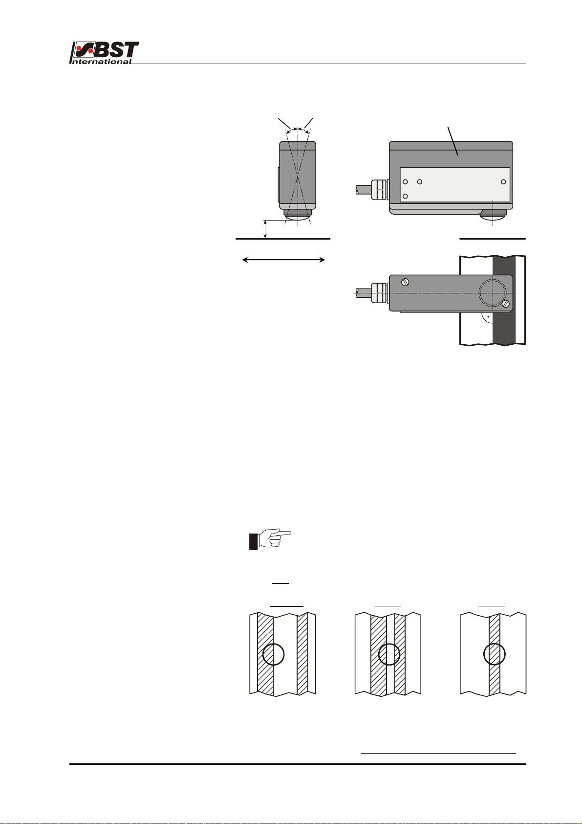
B 1.5.3 Installation
reflection sensor TW 54 C 5
5°…15°
5°…15°
TW 54 C 5
6…12
web running direction
You must abide by the following points when installing the
TW 54 C 5 reflection scanner in order to realise optimum guiding
results:
• The line sensor should be mounted on a torsionally rigid base.
• The line / contrast must be placed at right angles to the
longitudinal axis of the sensor (see drawing).
• The scanning should be carried out on a deflection roller.
This will ensure that any material web height fluctuations are
eliminated at the scanning point.
• The distance between the sensor scanning optics and the
material web has to be 6 - 12 mm, depending on the required
measuring range (diameter of the light spot).
The measuring range (light spot diameter)
depends on the distance between the contrast
transitions.
Only one
contrast transition may be located within the light spot.
correct
wrong wrong
Distance scanning optics D material web: 6 - 12 mm
Light spot diameter: 7.5 – 4 mm
• We recommend that the sensor angle is reduced by 5° - 15° in
the web running direction when using very reflective materials
60
ekrPro Com
web guide controller EDV No.: MD.191.01.05/1.6.x Chapter: B 1
with analog sensors Date: 23.11.2007 Page: 7/7
.

Controls B 2
B 2 Display and operating controls
B 2.1 Control panel
Graphics display
A contrast-rich LCD display with LED background illumination.
Display has 6 lines, each of 28 characters.
The graphics display is used for displaying the operating hours,
parameters and the set-up menus.
Keypad
The controller can be configured for operation using this keypad.
Key Function
+
Automatic guiding
Manual positioning
Centring the guiding device (servo-center)
Left web edge guide
Right web edge guide
Web center guiding
Edge / contrast control:
Contrast transition: light / dark
Edge / contrast control:
Contrast transition: dark / light
ekrPro Com
with analog sensors Date: 23.11.2007 Page: 1/6
60
web guide controller EDV No.: MD.191.01.05/1.6.x Chapter: B 2
’Automatic’ operating mode:
• Moves the setting to the left/right
’Manual’ operating mode:
• Manual left/right positioning of the
guiding device
• Change between the operating status
displays

Controls B 2
Key Function
B 2.2 Navigating within the system
Use the arrow keys and the F1 – F4 function keys to navigate
within the system.
The different functions are explained in the following.
If incorrect entries are made, or if functions are active which, for
example, prevent entering of parameters (e.g. keyboard lock) the
appropriate message windows are shown on the display for
5 seconds
This gives the user information about which error is present in the
current case. The message can be deleted using the "OK" key.
Menu navigation:
In editing box:
Jump back by one level
Cancels the last entry
Select controller settings or controller gain
for change the settings
Saves the settings at the end of the set-up
functions
Activates special functions
(e.g. oscillation)
(not used at the present moment)
Menu selection
ekrPro Com
60
web guide controller EDV No.: MD.191.01.05/1.6.x Chapter: B 2
with analog sensors Date: 23.11.2007 Page: 2/6

Controls B 2
B 2.2.1 Function keys (F-keys)
The F-keys functions are assigned in different dialog windows. The
associated abbreviated names are displayed at the bottom edge of
the screen.
Press the relevant F-key several times to select the required
numerical value. The time interval in between pressing the button
twice must never exceed 0.5 seconds.
Shortcut functions
The function keys are assigned numbers in the equipment menu.
Therefore a menu option can be selected by using the arrow keys
to navigate to the required menu sub-option or it can be selected
directly by using the shortcut number instead.
For example:
Selecting the actuator
The associated menu sub-option is 611
(see navigation overview as well).
1. Press key . This will display the set-up menu.
1
Current position
in device menu
Assignment of allocated
function keys
To enter the shortcut number:
2. Press F2 key 3x = 6.
51
The "General setup" menu including the first "Actuator"
submenu is called up.
3. Press the F1-key once = 1
Materia l Setup
Actuator
Sel. Std. System
Save/Load Settings
General Setup
opt. Logic
123 45 6 789 0
Type (EMS&Hydr.)
Sensors/EFE
Hydraulics Add-on
Control Loop
Direction
FVG
SC-Transducer
511
The required dialog will be displayed and you can now use the
arrow keys to select the parameter that has to be modified.
ekrPro Com
60
web guide controller EDV No.: MD.191.01.05/1.6.x Chapter: B 2
with analog sensors Date: 23.11.2007 Page: 3/6

Controls B 2
Entries in the editing box
The parameter values are entered directly in the editing box. This
can also be realised using the F-keys.
1. Open the required sub-menu and then press the ENTER key
to activate the editing box.
2. Use the horizontal arrow keys to mark the initial
position for the settting.
Width Measure Offset
current width:
enter ref.width
123 456
3. Enter the number. For example: press F4 x 1 = 0.
The actual position will jump automatically by 1 place to the
right after 0.5 seconds without an entry being made.
4. Now enter the next number in the same way as described
above in Section 3.
5. Press the ENTER button to import the modified value.
6. Press the ESC button to cancel the value.
Editing box
The arrow keys can also be used to enter a value in the editing box
in addition to using the F-keys.
Width Measure Offset
current width:
enter ref.width
123 456
Use the horizontal arrow keys to position the cursor on
the number to be modified.
Now use the vertical arrow keys to increase or decrease
the number.
Press ENTER to import the entered value.
Press the ESC button to cancel the value if you do not want to
save it.
789 0
mm
78.5
0
mm
78.5
0
789 0
Opened
editing box
Selected
digit
Opened
editing box
ekrPro Com
with analog sensors Date: 23.11.2007 Page: 4/6
60
web guide controller EDV No.: MD.191.01.05/1.6.x Chapter: B 2

Controls B 2
Entering negative numbers
Use the horizontal arrow keys to mark the initial
position for the setting.
Now use the vertical arrow keys so that the minus sign
is entered or removed.
After this, enter the digit sequence as described above.
B 2.2.2 Arrow keys
Various entries can be made and options can be selected from the
menu mode dialog windows.
The procedure for the various controls and lists is as follows:
Control elements
Use the arrow keys to mark the required control if there are several
control elements displayed in the same dialog window.
For example:
sens.mode W XP
0
0
0
0
5.00
5.00
5.00
5.00
Use the ’right’ arrow key to scroll forward and
use the ’left’ arrow key to scroll backwards.
The vertical arrow keys do not have a function here.
Option lists
An entry from a default list can be selected from an option list. This
is realised by pressing the ENTER button to open the selected
option list.
Example:
Select an actuator type
EMS 17
Select an actuator type
EMS 10
EMS 16
EMS 17
123 456 789 0
The “▼“ or “▲“ symbols displayed on the right of the option list
indicate that there are more entries in list than are displayed on the
screen.
Use the vertical arrow keys to mark the position in the
list.
Confirm the selection by pressing ENTER.
ekrPro Com
60
web guide controller EDV No.: MD.191.01.05/1.6.x Chapter: B 2
with analog sensors Date: 23.11.2007 Page: 5/6

Controls B 2
Checkbox
Use the vertical arrow keys
Arrow keys option using the checkbox control element.
Example:
(de)activate speed control
active
X
X = Option active
= Option inactive
Read-only Checkbox
Read-only checkboxes only have a display function.
These give the operator reports about the current status of the
components (e.g. stop switch statuses).
Example:
= activated
= not activated
B 2.2.3 Buttons
Button control elements are present in certain dialog windows
Select a sensor type
sensor1
<<<
dark
-2048 abs. 1775
auto
IR 2005
7%
dark
Inv.
bright
2047
bri.
If a button is marked and the ENTER button is pressed afterwards,
an action will be executed (e.g. traversing the actuator).
The button will be displayed as being pressed down and the action
will continue to be executed all the time that the ENTER button is
kept pressed down.
=
ekrPro Com
60
web guide controller EDV No.: MD.191.01.05/1.6.x Chapter: B 2
with analog sensors Date: 23.11.2007 Page: 6/6

Commissioning B 3
B 3 Commissioning
B 3.1 General information
The controller ekrPro Com
the control system (connected sensors, actuator, sensor adjustment
unit, ...) using the system parameters in the individual setup menus.
The required parameters have already been entered if the control
system is an integral part of a projected BST system. You do not
have to reset anything with regard to this.
A new system configuration is required if components or the
controller have been exchanged on-site.
The range of the settings and therefore the set-up menus that have
to be taken into consideration depend on the system being used.
To simplify commissioning, the commissioning staff can select his
system from a list of the most common standard systems (see
chapter B.3.5).
Following the selection, all of the basic settings are automatically
entered in the setup menu.
Finally the commissioning staff has only to check a few applicationrelated settings and if necessary adjust them accordingly.
The procedures to be used with the separate menus are described
in section B 3.7.5 General set-up.
Danger from mains voltage!
Never open the controller before switching off the
mains!
60
is matched to the actual configuration of
ekrPro Com
60
web guide controller EDV No.: MD.191.01.05/1.6.x Chapter: B 3
with analog sensors Date: 23.11.2007 Page: 1/73

Commissioning B 3
B 3.2 Electrical connections
The system must be wired according to the accompanying
connection diagram or plugged into the appropriate cable sockets.
Standard wiring sleeves with collars (DIN 46228/Part 4) must be
used with all cable connections up to 0.75 mm².
Wiring sleeves must not be used with cables from 0.75 mm² up to a
maximum of 1.5 mm².
Using wiring sleeves:
The spring-loaded terminals have been optimised for square
crimping. This can be realised using, for example, ‘WAGO’ variocrimp pliers.
This type of crimping also enables the connection to be connected
and disconnected without any problems.
The crimping is also gas-tight, i.e. there is no space inbetween the
conductor and the wiring sleeve.
Using cable without wiring sleeves:
For fine and multi-core cable and for fine-wired cable, whose kink
resistance is not sufficient due to its small diameter, in order to
overcome the contact force of the clamping springs, the clamp must
be correctly opened using a screwdriver.
Check that all the cables are fitted tightly after the connections have
been made (in both cases).
The ekrPro Com
connection.
If the supply voltage was inversely connected to terminals 42
and 43 of the controller, this inverse polarity would also be
connected to the 24 V output socket.
This could lead to damage to components connected to this
socket.
Attention! Applications with a sensor adjustment unit!
60
controller is protected against incorrect
The stepping motor output stages are not
protected against
short circuits.
You must check, without fail, using a suitable test unit
(ohmmeter) that no short circuits or cross-connections
between the two windings exist before starting the
commissioning.
ekrPro Com
60
web guide controller EDV No.: MD.191.01.05/1.6.x Chapter: B 3
with analog sensors Date: 23.11.2007 Page: 2/73

Commissioning B 3
B 3.3 Commissioning
with a CAN Bus
B 3.3.1 Checking the unit address
and setting up if necessary
If the ekrPro Com
setting of the CAN device address must be checked.
The CAN device address setting up is carried out via the S1 BCD
switch on the processor board:
The ekrPro Com
state).
• Set the S1 BCD switch to "1" if the ekrPro Com
device connected to the CAN bus.
60
controller is operated via a CAN bus, then the
BCD switch S1
60
address is preset to "1" in the factory (delivery
60
is the only
• If you want to run several
ekrPro... family devices on one CAN bus
system, then different device addresses (1 – 8) must be set for
the devices.
One of the devices must be set to device address "1" without
fail! Device addresses 0 and 9 are reserved.
Each device address can only be used once per guiding
system!
Procedure:
1. Switch-off the power to the controller.
2. Open controller’s front cover.
3. Set S1 BCD switch to the required device address (1 – 8).
4. Close the controller’s front cover.
5. Restore the power.
ekrPro Com
60
web guide controller EDV No.: MD.191.01.05/1.6.x Chapter: B 3
with analog sensors Date: 23.11.2007 Page: 3/73

Commissioning B 3
ekrPro Key
60
(if fitted) :ekrPro Key60:
There are several plugs on the rear side of the
ekrPro Key
60
.
The BCD switch S1 for setting the address (node
number) is behind these plugs.
Procedure:
S1 BCD switch
1. Switch-off the power to the controller.
2. Remove the plug.
3. Check setting of BCD switch S1. If necessary, set
device address to S1 = 1.
4. Refit the plug.
5. Restore the power.
FVGPro Module (if fitted
) :FVGPro Module”
The device address setting up is also crried out via the
S1 BCD switch mounted on the board:
Procedure:
1. Switch off the power to the FVG Pro module.
2. Open housing’s front cover.
3. Check the setting of the BCD switch S1. If
necessary, set device address to S1 = 1.
4. Close the controller’s front cover.
5. Restore the power.
S1 BCD switch
The device address modification will be effective after the
power has been restored
.
ekrPro Com
60
web guide controller EDV No.: MD.191.01.05/1.6.x Chapter: B 3
with analog sensors Date: 23.11.2007 Page: 4/73

Commissioning B 3
B 3.3.2 Terminator activation
The terminator must be activated on each of the physical first
and
last CAN bus participants. The possible settings are described
below.
In the ekrPro Com
60
, the activation is carried out using switch S3 on
B 3.3.2.1 ekrPro Com
60
the processor circuit board. Set the switch to "ON“.
Terminator S3
Procedure:
B 3.3.2.2 ekrPro Key
60
(if fitted)
1. Switch-off the power to the controller.
2. Open controller’s front cover.
3. Activate terminator S3 (switch position ON)
4. Close the controller’s front cover.
5. Restore the power.
In the ekrPro Key
60
activation
is carried out via switch S3.
Remove plug on the
back side.
Set the switch to "ON“.
Switch S3
ekrPro Com
60
web guide controller EDV No.: MD.191.01.05/1.6.x Chapter: B 3
with analog sensors Date: 23.11.2007 Page: 5/73

Commissioning B 3
B 3.3.2.3 BST ProLogic
(if fitted)
In the BST ProLogic activation takes place using the DIP switch
segment 1 (S1 = ON) for the CAN 1.
CAN 2
B 3.3.2.4 FVGPro Module
(if fitted)
In the FVGPro Module activation is carried out via switch S3 on the
processor circuit board. Set the switch to "ON“.
Switch S3
Procedure:
1. Switch-off the power to the module.
2. Open module’s front cover.
3. Activate terminator S3 (switch position ON)
4. Close the module’s front cover.
5. Restore the power.
ekrPro Com
60
web guide controller EDV No.: MD.191.01.05/1.6.x Chapter: B 3
with analog sensors Date: 23.11.2007 Page: 6/73

Commissioning B 3
B 3.4 Adjust password
User administration in the ekrPro Com
60
differentiates between four
different user levels with different user rights.
The individual user levels are each protected by a password.
Dependent on the selected user level, more or fewer paths are
activated in the setup menu. Non-activated entries are greyed out in
the menus and cannot be selected.
The user levels with the corresponding user rights are shown in the
following table.
User level Rights Default Password
Operator
(Operator)
Mainten.
Maintenance
personnel
Admin.
Administrator
BST Support
(BST-Service
• No rights to make changes in the setup menus.
• Unlimited changing rights in the menu
“Material Setup”.
• Unlimited rights to make changes in the setup menus.
• As for “Admin.” (only for BST servicing purposes)
The unit is supplied with the user level Admin set.
The indicated default password should only be used for the first
access to the setup menu and then an application-appropriate
password entered. This is also true for the Mainten. user level. This
protects the system against unauthorized access.
Make sure these new passwords are only known to the authorized
personnel!
BST International GmbH is not liable for damage arising from the
incorrect use of the password(s).
An automatic logout time can be set for all user levels (timeout time).
If no key is pressed for the set time, the user is automatically logged
out and the controller changes to the user level Operator.
Changes to passwords and the timeout time is undertaken from the
menu General Setup > Special > Change Pwd
All passwords can be reset to the default passwords up to 20
seconds after switching on of the controller by pressing the key
combination F4” + “ESC.
When the controller is switched-off, the last active user level is
stored and automatically activated after a reboot.
The procedure for selecting the user level is described in the
following pages.
0
1
2
ekrPro Com
60
web guide controller EDV No.: MD.191.01.05/1.6.x Chapter: B 3
with analog sensors Date: 23.11.2007 Page: 7/73

Commissioning B 3
Selection of user level is undertaken from the Change User menu.
1. Select Change User menu and press ENTER.
Enter user level & password
User level
Password 0
Current
user level: Admin.
logout
Operator
login
2. The user level selection window appears.
In the lower part of the window the active user level is
displayed (Admin. in the example).
Enter user level & password
User level Operator
Password
Current
user level BST Support
123 456 789 0
Mainten.
Admin.
Press the ENTER button and the user level option list will then
be opened.
Select the desired user level with the up and down arrow
keys.
Confirm the selection by pressing ENTER.
Enter user level & password
User level Mainten.
Password
Current
user level: Admin
123 456 789 0
00000
3. Use the right and left arrow keys to select the Password
editing box and press ENTER.
Enter user level & password
User level Mainten.
Password
Current
user level: Admin
logout
1
login
Enter the password and confirm the entry with ENTER.
4. Press the F3-key (login).
The controller changes to the selected user level.
The Setup menu selection window appears.
Entries, for which there are no user rights in the selected user
level are shown greyed out.
ekrPro Com
60
web guide controller EDV No.: MD.191.01.05/1.6.x Chapter: B 3
with analog sensors Date: 23.11.2007 Page: 8/73

Commissioning B 3
B 3.5 Commissioning standard system
To simplify commissioning, the commissioning staff can select his
own system from a list of the most common standard systems listed
under the menu Sel. Std. System.
B 3.5.1 Select standard system
F1 for fa ct. def aults
Choose standard system …
select a standard config.
… & press F2 to acti vate
Set.Def.
F1 for fa ct. def aults
Choo se st andar d sys tem …
sele ct a sta ndard conf ig.
… & pr ess F2 to activate
Set.Def.
Following the selection, all of the basic settings are automatically
entered in the setup menu and the system is switched to the
operating mode MAN.
1. Press the MENU button.
The setup menu of the controller appears in the display.
2. Select menu "Sel. Std. System“ and press ENTER.
3. The selection window for the standard system will appear.
4. Press the ENTER button.
The option list opens with the most common standard
systems. Individual entries each contain the following
information:
Type of connected
sensor(s)
Type of connected
actuator
Type of the
sensor positioning device
(if fitted)
5. Use the vertical arrow keys to select the system that matches
the present system.
Confirm the selection with the ENTER key.
The selected system is displayed.
6. To import the standard system configuration, press
function key F2 (set.).
The selection is confirmed by the message window Standard
System Set.
The base settings in the setup menu are automatically
entered by the system.
After this, the selection window is displayed again.
7. Press the ESC button to exit the window.
Attention!
After selecting the standard system, adjustment for a
particular application (e.g. material properties) must
take place.
Accordingly, the following steps should be carried out:
ekrPro Com
60
web guide controller EDV No.: MD.191.01.05/1.6.x Chapter: B 3
with analog sensors Date: 23.11.2007 Page: 9/73

Commissioning B 3
B 3.5.2 Carry out master setup
The sensor type will already have been set when the standard
system was set.
The procedure is described for Sensor 1.
The master set-up for Sensors 2 and 3 is the same.
1. Select Sensors/EFE in General set-up and then select the
Sensor 1 sub-directory afterwards. Confirm the respective
selection by pressing ENTER.
2. Select the type of sensor that is connected to the system from
the option list displayed in the new window that has opened
up and then enter it.
Attention!
If the mounting position of the selected sensor differs from the
BST setting (see chapter A 1.4) or if the sensor outputs an
inverted signal (e.g. another manufacturer’s sensor is being
used), then the checkbox Inv. must be checked.
A master set-up will be carried out afterwards.
Master set-up can be run automatically or manually.
dark
Inv.
bright
2047
bri.
3. Automatic master set-up:
► Press the F1 button and then cover the sensor’s scanning
window with an opaque material for two seconds
afterwards.
Select a sensor type
sensor1
<<<
dark
-2048 abs. 1775
auto
IR 2005
7%
► Remove the material from the scanning window and press
the F2 button two seconds later.
► This completes the master set-up for this sensor.
4. Manual master set-up:
► Cover the sensor’s scanning window with an opaque
material and then press the F3 button.
► Remove the material so that the window is completely
uncovered and press the F4 button.
5. Run the master set-ups for Sensors 2 and 3.
ekrPro Com
60
web guide controller EDV No.: MD.191.01.05/1.6.x Chapter: B 3
with analog sensors Date: 23.11.2007 Page: 10/73

Commissioning B 3
B 3.5.3 Setting the actuator
guiding direction
For standard systems, the EMS17 is registered as the actuator.
The direction has to be set for it.
1. Select the sub-directory Direction from the menu Actuator.
Confirm the selection by pressing ENTER.
If necessary, the actuator guiding direction for manual mode
can be reversed by activating the checkbox Mot. Dir. Inverted.
The rotational direction can be checked on the spot.
Drive the actuator using the F2 or F3 key.
If key F2 is pressed, the actuator must move the material web
Toggle Man Dir. until
F2 moves to sensor 1
Mot. Dir. Inverted
in the direction of sensor 1, if F3 is pressed it must move it
towards sensor 2!
Pressing F2 or F3 automatically changes the controller to
“manual” operating mode.
The sensor allocation can be checked on the spot. Press the
MENU button. The operating display is shown.
Cover one sensor. The change to the coverage range shows
the allocation.
After this, press the MENU key to ENTER to the settings
menu.
2. Press the ESC button to exit the window.
B 3.5.4 Setting the actuator
path limits
From here it is possible to limit the adjustment travel of the
actuator.
Change User
Actuator
Material Setup
Sel. Std. System
General Setup
opt. Logic
123 456 789 0
Type (EMS&Hydr.)
Sensors/EFE
Control Loop
FVG
Type & Dir.
Hydraulics Add-on
Pos. Limit
Directions
SC W & XP
SC-Transducer
1. Select Actuator in General Setup, then the sub-directory
SC-Component and finally Pos. Limit.
Confirm the respective selection by pressing ENTER.
2. Use the vertical arrow keys to deactivate the checkbox active.
This deactivates the function of both limit switches.
The settings can only be entered in the deactivated state.
3. Use the F2 key to drive the actuator until it reaches the
required left limit switch position.
The actual position of the actuator supplied by the position
feedback is shown in the middle above the F2 and F3 keys.
4. Confirm this position by pressing the F1 key.
The limit switch position is stored.
The corresponding position value is shown below the
checkbox.
ekrPro Com
60
web guide controller EDV No.: MD.191.01.05/1.6.x Chapter: B 3
with analog sensors Date: 23.11.2007 Page: 11/73

Commissioning B 3
5. Use the F3 key to traverse the actuator until it reaches the
required right limit switch position.
6. Confirm this position by pressing the F4 key.
7. Reactivate both limit switches.
Select (x) checkbox active to do this.
The description is given in section 2.
Import of the limit switch position is indicated by a black circle
in the read-only checkbox above the F1 and/or F4 key.
Confirm the selection by pressing ENTER.
8. Press the ESC button to exit the inputting menu.
B 3.5.5 Setting centre position
and gain for “SC” operating mode
From here the centre position and the amplification for operating
mode SC are set.
1. Select Actuator in General Setup, then the sub-directory
SC-Component and finally SC W & XP.
2. Press ENTER to open the inputting menu and enter the
parameters.
3. The current actuator position will be displayed in the field
mot.pos..
4. Use the F2 and F3 keys in MAN operating mode to traverse
the actuator into the required position.
5. Press the F4 key if you want to save the current position as
the setpoint value for the centring position.
The setting from mot.pos. will be imported into set-point W.
6. The setpoint value setpoint W and the gain gain XP can also
be entered directly in the relevant window.
7. The settings can be checked on the spot by switching over to
the SC operating mode.
8. Press the ESC button to exit the window.
ekrPro Com
60
web guide controller EDV No.: MD.191.01.05/1.6.x Chapter: B 3
with analog sensors Date: 23.11.2007 Page: 12/73

Commissioning B 3
B 3.5.6 Carry out material setup
Automatic adjustment of the controller to match the characteristics of
the material to be scanned is carried out during material set-up
(e.g. different material transparency at the optical sensors or
different sound absorption in the case of ultrasonic sensors).
The material set-up is the same for all three sensors.
The procedure for sensor 1 is used as the example here:
1. Press the MENU button to open the set-up menu.
2. Select Material set-up and confirm by pressing ENTER.
3. Select Sensor 1 and confirm by pressing ENTER.
This will open the Sensor 1 material set-up window.
Material Setup - Sensor 1
<<<
dark
-2048 abs. 1775
auto
7%
dark
bright
2047
bri.
Material set-up can now be carried out either automatically or
manually.
The manual procedure should always be used if the contrast that
has to be scanned is critical.
ekrPro Com
60
web guide controller EDV No.: MD.191.01.05/1.6.x Chapter: B 3
with analog sensors Date: 23.11.2007 Page: 13/73

Commissioning B 3
B 3.5.6.1 Automatic material set-up
1. Press the F1-key.
2. Completely cover the sensor’s scanning window with the
material to be scanned for approx. 2 seconds.
3. Completely remove the material from the sensor scanning
window (no material over the sensor).
4. Press the F2-key.
This completes the material set-up for this sensor. Material set-up is
finished when the same procedure has been carried out for any
other sensors connected to the controller.
B 3.5.6.2 Manual material set-up
1. Completely cover the sensor’s scanning window with the
material to be scanned.
2. Press the F3-key.
3. Completely remove the material from the sensor scanning
window (no material over the sensor).
4. Press the F4-key
The sequence is arbitrary, i.e. the dark setting (steps 1 and 2) or the
bright setting (steps 3 and 4) can be made first.
For sensors TW54 and T62, you must use the special
Material-Setup – Sensor 3 (see Point C 2.3.4).
ekrPro Com
60
web guide controller EDV No.: MD.191.01.05/1.6.x Chapter: B 3
with analog sensors Date: 23.11.2007 Page: 14/73

Commissioning B 3
B 3.5.7 FVG - Sensor positioning device
The stepping motor output stages are not
protected against
short circuits.
You must check, without fail, using a suitable test unit
(ohmmeter) that no short circuits or cross-connections
between the two windings exist before starting the
commissioning.
The connection cable from the ekrPro Com
60
control unit to the
sensor adjustment unit must not exceed the maximum cable
length of 20 m.
Power is continuously applied to the stepping motor output
stage, even when stopped. Therefore any work undertaken on
the interconnections must only be carried out with the power
switched off.
B 3.5.7.1 Default values set
Depending on the configuration selected under Select Standard
System, various default settings are carried out in the FVG
submenu.
B 3.5.7.1.1 Configuration-dependent default values
1. Selection IR2005:EMS 17 or US2007:EMS 17
For this selection, the sensor positioning device connection
entitled "not connected" is selected and entered. No additional
entries have to be carried out.
2. Selection IR2005:EMS17:1MK60 or IR2005 EMS17:1MK75
resp. US2007:EMS17:1MK60 or US2007:EMS17:1MK75
If one of these configurations is selected, the FVG 1MK Op. sensor
positioning device connection is selected and entered.
The following settings-dependent parameters are selected and
entered:
- Homing Direction – retraction direction and limit switch assignment
• at the first setting after switching on: not reversed
- Offset 1:
• at the first setting after switching on:
Offset = 0
Inverted = no
- Offset 2:
• at the first setting after switching on:
Offset = 2000
Inverted = yes
ekrPro Com
60
web guide controller EDV No.: MD.191.01.05/1.6.x Chapter: B 3
with analog sensors Date: 23.11.2007 Page: 15/73

Commissioning B 3
- Range – Traversing range limits
• at the first setting after switching on:
min = 0.0
max = 5000.0
- Feed – Feed for stepping motor / gearing combination
This setting is treated as the feed per motor revolution for the
stepping motor / gearing combination.
The respective value is automatically entered when the FVG type
is selected:
for FVG 1MK60 = 20088
for FVG 1MK75 = 61666.
The manufacturer has entered this default setting and you are
only permitted to modify it (if necessary) after having obtained the
manufacturer’s agreement.
The relevant procedure then has to be agreed.
All warranty claims will be invalidated in any other case.
3. Selection IR2005:EMS17:2MK60 or IR2005 EMS17:2MK75
resp. US2007:EMS17:2MK60 or US2007:EMS17:2MK75
If one of these configurations is selected, the "FVG 2MK Op.“
sensor positioning device connection is selected and entered.
The following settings-dependent parameters are selected and
entered for the FVG 1 (Slide 1)and the FVG 2 (Slide 2):
Slide 1
- Homing Direction – retraction direction and limit switch
assignment
• at the first setting after switching on: not
reversed
- Offset - positional offset to FVG position
• at the first setting after switching on: Offset = 2000
Inverted = no
- Range – Traversing range limits
• at the first setting after switching on:
min = 0.0
max = 5000.0
- Feed – Feed for stepping motor / gearing combination
This setting is treated as the feed per motor revolution for the
stepping motor / gearing combination.
The respective value is automatically entered when the FVG type
is selected:
for FVG 2MK60 = 20088
for FVG 2MK75 = 61666.
The manufacturer has entered this default setting and you are
only permitted to modify it (if necessary) after having obtained the
manufacturer’s agreement.
The relevant procedure then has to be agreed.
All warranty claims will be invalidated in any other case.
ekrPro Com
60
web guide controller EDV No.: MD.191.01.05/1.6.x Chapter: B 3
with analog sensors Date: 23.11.2007 Page: 16/73

Commissioning B 3
Slide 2
- Homing Direction – retraction direction and end switch
assignment
• at the first setting after switching on: not
reversed
- Offset - positional offset to FVG position
• at the first setting after switching on: Offset = 2000
Inverted = yes
- Range – Traversing range limits
• at the first setting after switching on:
- Feed – Feed for stepping motor / gearing combination
This setting is treated as the feed per motor revolution for the
stepping motor / gearing combination.
The respective value is automatically entered when the FVG type
is selected:
for FVG 2MK60 = 20088
for FVG 2MK75 = 61666.
The manufacturer has entered this default setting and you are
only permitted to modify it (if necessary) after having obtained the
manufacturer’s agreement.
The relevant procedure then has to be agreed.
All warranty claims will be invalidated in any other case.
B 3.5.7.1.2 Configuration-independent default value
The following values are general settings, which can be selected
and entered as default values independently of the FVG selected.
- Retract Mode – free-running mode
min = 0.0
max = 5000.0
• at the first setting after switching on: SC & Man
- Norming Mode – Standardization Mode
Setting of the standardization mode is dependent on the type of
sensor being used.
Infrared sensors: The mode is always set to "bright/dark“.
Ultrasonic sensors: The mode is always set to "no norming“.
- Width Adjust – FVG operating mode for center line guiding
• at the first setting after switching on: Level Outer
ekrPro Com
60
web guide controller EDV No.: MD.191.01.05/1.6.x Chapter: B 3
with analog sensors Date: 23.11.2007 Page: 17/73

Commissioning B 3
- Repositioning – repositioning of the material after certain
events
The current position of the material web is saved once an event
takes place (e.g. web tear). Once the event has been rectified, the
material is repositioned to this position. This functionality is only
effective once pre-positioning has been activated.
- Velocities – adjustment of positioning speeds
• at the first setting after switching on:
Retract velocity: 60 mm / s
Edge push velocity: 5 mm / s
Slow manual velocity: 1 mm / s
Fast manual velocity: 60 mm / s
Norming velocity: 60 mm / s
- Special – Special settings for driving the FVG slides
• at the first setting after switching on:
Mode after error: Man
Carry out setting according to point B 3.7.5.5, if the settings listed
above, for the sensor adjustment unit, do not corresponding to the
operating requirements.
ekrPro Com
60
web guide controller EDV No.: MD.191.01.05/1.6.x Chapter: B 3
with analog sensors Date: 23.11.2007 Page: 18/73

Commissioning B 3
B 3.5.8 Add. Functions – Special functions
Useful additional functions can be realised using the ekrPro Com
60
These functions can be accessed quickly under this menu point.
These functions deal with the Tear Off Detection and Oscillation.
B 3.5.8.1 Tear-Off Det. – Tear-off detection
Tear-off detection enables, dependent on the selected sensing
type (edge / contrast guiding) the following functions:
1. With web edge guiding:
Detection of torn off sections on the web edge using edge
sensors IR2001/2005, US2007, …
This function is activated during web edge guiding, if during
operation of the web guiding system errors arise from the web
edge that is being scanned.
The function detects both tears into the material web (inward
tear) as well as projecting material (outward tear).
2. With contrast guiding:
Guiding on interrupted printed or contrast edges with contrast
sensors T62D1 or TW54C5.
Interrupted printed
or contrast edge
Light spot of the
contrast sensor
Tear-off
inwards
Tear-off
outwards
Tear-off detection can be implemented using the same sensors that
are used for web guiding.
Alternatively a second sensor can be used.
.
ekrPro Com
60
web guide controller EDV No.: MD.191.01.05/1.6.x Chapter: B 3
with analog sensors Date: 23.11.2007 Page: 19/73

Commissioning B 3
Criteria for detecting a tear:
To detect a tear, at least one of the two following criteria must be
fulfilled:
1. Exceeding / undershooting of the preset threshold value
If the sensor signal exceeds or falls below the set threshold value
(threshold), then this is recognised as a tear.
After a preset delay time (delay) has elapsed, the web guiding
system is automatically blocked.
Blocking of the guidance system is lifted, as soon as the sensor
signal again lies above/below the set threshold value and the set
run-on time (hold time) has elapsed.
2. Exceeding of the preset maximum rate of change of the sensor
signal.
The system continuously checks the rate of change speed of the
sensor signal in both positive and negative directions. If the
preset maximum permissible rate of change (sig. chg. lim.) is
exceeded, then this is recognized as a tear.
After a preset delay time (delay) has elapsed, the web guiding
system is automatically blocked.
If the set rate of change is undershot, then blocking of the guiding
system is not
lifted.
Lifting of the blocking is only implemented if the preset threshold
value (threshold) is again undershot (see point 1).
Conditions for guiding on interrupted printed or contrast edges
For trouble-free operation of the control unit, the following conditions
must be fulfilled:
1. Minimum mark length
The printed or contrast edge to be sampled must not fall below
the minimum mark length L
depends on the maximum web speed, v
. The minimum mark length
min
, the sampling cycle, t,
max
and the diameter, d, of the light spot of the contrast sensor used.
It can be calculated using the following formula.
Light spot
dL
L
min
V
[m/min]
[m] = * 3 * t [s] +
max
60 s/min
d [mm]
1000 mm/m
= minimum mark length [m]
L
min
v
= max. web speed [m/min]
max
t = sampling cycle [s] = 0.004 s
d = light spot diameter [mm]
ekrPro Com
60
web guide controller EDV No.: MD.191.01.05/1.6.x Chapter: B 3
with analog sensors Date: 23.11.2007 Page: 20/73

Commissioning B 3
Example calculation:
At a maximum web speed v
diameter d = 8 mm the resultant minimum mark length L
= 300 m/min and a light spot
max
min
,
equals:
L
300 m/min
= ¹ 3 ¹ 0,004 s ¬
min
60 s/min
8 mm
1000 mm/m
L
= 0,068 m = 68 mm
min
2. Alignment of the contrast sensor:
When scanning an interrupted line
, correct alignment
of the contrast sensor must be observed:
• The contrast sensor must be aligned so that the
edge
of the line is located in the sensor light spot.
• Only one
edge may be located within the light
spot.
correct
wrong wrong
3. Operating mode setting for the contrast sensor T 62 D 1
The operating mode selection switch on the sensor must be set
to the position Kante (edge).
Operating mode
selection switch
ekrPro Com
60
web guide controller EDV No.: MD.191.01.05/1.6.x Chapter: B 3
with analog sensors Date: 23.11.2007 Page: 21/73

Commissioning B 3
Parameter settings
Setting of the parameters for the function tear-off detection is made
separately for each guiding mode. If necessary, a different sensor
can be allocated as the tear-off detection sensor for each guiding
mode. It is also possible to allocate two different guiding modes with
different parameters to a single sensor.
1. Select Add. Functions in General Setup and then select the
Tear Off Det. sub-directory afterwards.
Confirm the respective selection by pressing ENTER.
2. Select the desired guiding mode (Edge 1, Edge 2, Edge 3,
Center 1&2) from the option list.
Confirm the selection by pressing ENTER.
3. This will open up the inputting window for the selected guiding
mode. The following separate parameters can be set:
► Sensor:
Selection of the sensor with which tear-
off detection is to be implemented.
► threshold [%]: Percentage covering of the sensor
measuring band, above which a change
is detected as a tear.
For the example value entered here
(80/20), this means that the function
detects a tear, if more than 80% or less
than 20% of the sensor measuring band
is covered.
► sig. chg. limit. [%/4ms]: Maximum permissible rate of
change of the sensor signal in %
per 4 ms
(Scanning cycle = 4 ms, i.e. the
sensor measurements are read
every 4 ms).
A tear is detected, if the rate of
change of the sensor signal
exceeds the percentage per 4 ms
set here.
The values to be set are
calculated according to the
formula on the following page.
► delay [ms]: Delay time in ms from detection of a tear
until blocking of the guiding system.
► hold [ms]:
Blocking hold time in ms after the
detected end of the tear until the blocking
is lifted, i.e. until the guiding system is
activated.
4. If necessary, set parameters for further guiding modes
(see points 2 and 3).
5. Press the ESC button to exit the window.
ekrPro Com
60
web guide controller EDV No.: MD.191.01.05/1.6.x Chapter: B 3
with analog sensors Date: 23.11.2007 Page: 22/73

Commissioning B 3
Calculation of the maximum allowable rate of change of the sensor
signal (parameter sign. chg. limit)
The maximum permissible rate of change sig. chg. limit of the
sensor signal, depends of the minimum web speed v
min
and
diameter d, of the contrast sensor light spot and can be calculated
using the following formula.
sig. chg. limit [%/4ms] = 2 ¹ * ¹ 100
V
[m/min]
min
60 s/min * d [mm]
sig. chg. limit = permissible rate of change [%/4ms]
= min. web speed [m/min]
v
min
d = light spot diameter [mm]
Example calculation:
At a minimum web speed v
= 30 m/min and a light spot diameter
min
d = 10 mm the resultant maximum rate of change of the sensor
signal equals:
sig. chg. limit [%/4ms] = 2 ¹ ¹ 100
30 m/min
60 s/min * 10 [mm]
sig. chg. limit [%/4ms] = 10 % /4ms
B 3.5.8.2 Oscillation
This special function enables the position of the web to be displaced
within the sensor´s visual range using adjustable amplitude (size of
the lateral displacement) and frequencies (displacement speed).
The format of the web displacement when the controller is operated
without a sensor positioning device follows a delta curve ( ).
When operated with a sensor positioning device, a sine-wave ( )
web displacement takes place. See also chapter A1, Point A 1.4.4‚
Oscillation types and curves’.
Osc. Mode – determine operating mode for oscillation mode
1. Select Add. Functions in General Setup and then select the
Osc. Mode sub-directory afterwards.
Confirm the respective selection by pressing ENTER.
2. The set value for the web width (Nominal Width) is entered in
this window. Activation then takes place in the operating
status display using the F1 key.
The following settings are possible:
• • OFF:
Oscillation is deactivated
(factory setting)
• Auto:
Activation in operating mode
Automatic
Repositioning of material web is
carried out within the sensor visual
area with adjustable amplitude.
ekrPro Com
60
web guide controller EDV No.: MD.191.01.05/1.6.x Chapter: B 3
with analog sensors Date: 23.11.2007 Page: 23/73

Commissioning B 3
• SC:
Activation in operating mode SC
using the servo-center component.
• FVG Auto:
Oscillation with connected FVG
An FVG oscillation with sine-shaped
web repositioning.
3. Press the ESC button to exit the window.
Osc. Params. – Set oscillation parameters
The oscillation parameters, i.e. amplitude and frequency, are
set in this submenu.
1. Select the Osc. Params submenu and confirm by pressing
ENTER.
2. The parameters have the following meanings:
► Amplit. Auto [%]:
Amplitude of the oscillation in operating
mode Automatic.
The percentage value relates to the size
of the sensor scanning area.
Setting range: 1 % to 99 %
► Amplit. SC [%]:
Setting up the amplitude for the SC
operating mode
The percentage wise input of the
amplitude relates to the distance
between the software limit switches.
One limit switch represents 0 % and the
other 100 %.
Setting range: 1 % to 99 %
► Amplit. FVG [mm]
Amplitude of oscillation when using a
sensor positioning device.
The sample value shown here of
10 mm results in repositioning of the
web by ± 5 mm.
Setting range: 0 to 999.9 mm
► Frequency [Hz]:
Oscillation frequency.
Setting range: 0.016 … 1.000 Hz
3. Press the ESC button to exit the window.
ekrPro Com
60
web guide controller EDV No.: MD.191.01.05/1.6.x Chapter: B 3
with analog sensors Date: 23.11.2007 Page: 24/73

Commissioning B 3
Osc. Params Add-on – Additional functions for oscillation
(can only be used for the sensor oscillation)
Additional specifications can be set for the sequence of the
oscillation in this sub-menu.
1. Select the sub-menu Osc. Params Add-on and
confirm with ENTER.
2. The parameters displayed in the setting menu have the
following meanings:
Oscillation Add-on:
► start/stopp at act.pos:
When the function is activated, the
oscillation will continue at the position
>> NOT FOR FVG OSC.!<<
where it was stopped.
► start osc. after restart:
When the function is activated, the
oscillation is immediately started when
the system is switched back on.
B 3.6 Save settings
Once the parameters have been determined for the current system,
they can be saved. This enables the facility to access them again at
any time in the case that modifications have been carried out
unintentionally or by unauthorized persons.
1. Press the MENU button.
The Setup menu appears in the display.
2. Select Save/Load Settings menu and press ENTER.
3. Saving or loading the settings can now be carried out using
keys F2 or F3.
F2 = Save the entered setting
F3 = Load saved values
4. Press the ESC button to exit the window.
Attention! This setting cannot be copied to another
controller or saved externally.
ekrPro Com
60
web guide controller EDV No.: MD.191.01.05/1.6.x Chapter: B 3
with analog sensors Date: 23.11.2007 Page: 25/73

Commissioning B 3
B 3.7 Setup menu
The system parameters are saved in the Setup menu and they can
also be modified from here. The menu structure is shown in
Appendix D1.
B 3.7.1 Change User
Selection of user level-
User administration in the ekrPro Com
different user levels with different user rights.
The individual user levels are each protected by a password.
The procedure for selecting the user level is described in detail in
chapter B 3.4.
B 3.7.2 Material Setup - Sensor co mpensation
Automatic adjustment of the controller to match the characteristics of
the material to be scanned is carried out during material set-up
(e.g. different material transparency at the optical sensors or
different sound absorption in the case of ultrasonic sensors).
The procedure for material setup is described in chapter C 2.3.
B 3.7.3 Sel. Std. System –
Selection of a standard system
To simplify commissioning, the commissioning staff can select his
own system from a list of the most common standard systems listed
under the menu "Sel. Std. System".
Following the selection, all of the basic settings are automatically
entered in the setup menu.
60
differentiates between four
B 3.7.4 Save/Load Settings
The procedure for selecting a standard system is described in detail
in chapter B 3.5.
You can use this function to save user-defined settings in the system
and call them up again. This gives you the facility for accessing them
at any time in the case that modifications have been carried out
unintentionally or by unauthorized persons.
The procedure for selecting a standard system is described in detail
in chapter B 3.6.
ekrPro Com
60
web guide controller EDV No.: MD.191.01.05/1.6.x Chapter: B 3
with analog sensors Date: 23.11.2007 Page: 26/73

Commissioning B 3
B 3.7.5 General Setup -
System parameters
All of the parameters that have to be set up once when aligning the
system are contained in the General set-up.
The following procedures are provided for the different operating
modes.
However, the default values should be loaded before the special
parameters are set up. This will meet the condition for a
standardised basic output.
B 3.7.5.1 Setting the default values
1. Go to the General set-up menus and then select Sel. Std.
System
F1 for fa ct. defaul ts
Choo s e st andar d system …
sele c t a sta ndard config .
… & press F2 to activate
Set.Def.
2. Press the F1-key. The default settings will be loaded.
3. Press the ESC button to exit the window.
4. The application specific parameters can be set up now.
ekrPro Com
60
web guide controller EDV No.: MD.191.01.05/1.6.x Chapter: B 3
with analog sensors Date: 23.11.2007 Page: 27/73

Commissioning B 3
B 3.7.5.2 Actuator – Actuator settings
B 3.7.5.2.1 Type (EMS&Hydr.) – Actuator selection
The relevant servo center component must be entered before
starting the commissioning
(see chapter B 3.7.5.2.4 ”servo-center component settings“).
Any remote control which may possibly be running, must be
deactivated!
The preset actuator is the EMS 17.
Actuator path limits and the servo-center component have to be
adjusted.
If a different motor-driven or hydraulic actuator is being used it
should first be selected from the option list.
The actuator selection procedure is shown on the left.
1. Press the MENU button, select General Set-up from the sub-
menu and then press ENTER.
2. Select Actuator in General Setup and then select the
Type (EMS&Hydr.) sub-directory afterwards.
Confirm the respective selection by pressing ENTER.
Mate rial Set up
Actuator
Sel. Std. System
Save/Load Settings
General Setup
opt. Logic
123 45 6 789 0
Type (EMS&Hydr.)
Sensors/EFE
Hydraulics Add-on
Control Loop
Direction
FVG
SC-Transducer
3. The default actuator will be displayed on the screen.
Press the ENTER button and the actuator option list will then
be opened.
Now use the vertical arrow keys to select the actual actuator
that is connected to the system.
Motor-driven actuators: EMS …
Select an actuator type
EMS 17
Hydraulic actuators: hyd. … mA
If a hydraulic actuator is used, then additional
Note:
hydraulic settings must be made in the menu
Hydraulics Add On (see the following page).
Confirm the selection by pressing ENTER.
Select an actuator type
EMS 10
EMS 16
EMS 17
Press the ESC button to exit the window.
123 456 789 0
ekrPro Com
60
web guide controller EDV No.: MD.191.01.05/1.6.x Chapter: B 3
with analog sensors Date: 23.11.2007 Page: 28/73

Commissioning B 3
B 3.7.5.2.2 Hydraulics Add-on – Hydraulic settings
If a hydraulic actuator is used, then additional hydraulic settings
must be made in the menu Hydraulics Add On.
1. Select Actuator in General Setup and then select the
Hydraulics Add-on sub-directory afterwards.
Confirm the respective selection by pressing ENTER.
2. This will open an inputting window, in which the settings for
the connected hydraulic actuator have to be entered.
The relevant settings are listed in the following table:
Zero elevation [%]
Dither amplitude [mA]
Use teach table
Specific current control
Teach
0
0
Unit
name
Actuator
Type
Dither
amplitude
[mA]
Zero
elevation
[%]
Specific
current
control
SV 1-10/4 300 mA 10 0 No
SV 1-10/8 300 mA 10 0 No
SV 1-10/16 300 mA 20 0 No
SV 1-10/32 300 mA 20 0 No
SV 1-10/48 1000 mA 40 0 No
SV 1-6 300 mA 20 0 No
HR 024 300 mA
1*
No
HR 040 300 mA 20 0 No
EH-St 9/3 300 mA 25 5 No
The dither frequency is 50Hz.
1* This setting is dependent on the fitted continuously operated
valve SV 1-10/x.
3. The system must be optimized to the actual settings after the
parameters have been entered. This is realised by an
integrated self-teach function.
Press the F3 key to start this function.
This will import the throughput curve for the hydraulic
actuator. The measured values are saved in table as nonvolatile settings.
Attention! The hydraulic actuator will traverse during the
teach process. The relevant safety arrangements
Zero elevation [%]
Dither amplitude [mA]
Use teach table
Specific current control
Teach
0
0
X
The flow curve determined for the controller must be activated in the
window if it is to be used.
must be implemented.
ekrPro Com
60
web guide controller EDV No.: MD.191.01.05/1.6.x Chapter: B 3
with analog sensors Date: 23.11.2007 Page: 29/73

Commissioning B 3
Digital blocking output (oil blocking)
If a hydraulic actuator is used, then a blocking valve can be
connected to terminal 67 (X15), in order to interrupt the oil flow.
Oil blocking is only active with a hydraulic actuator and when one of
the following conditions is fulfilled:
• Man output = 0 and position controller deactivated.
• A limit switch position is reached.
• An over-temperature and a short circuit exist.
• Missing enable for the actuator:
(see actuator enable terminal 53)
Behaviour when oil blocking is switched on:
• PWM and analogue output are blocked.
• Blocking is activated after a 150 ms delay
(OV at terminal 67 (X15)
Behaviour when oil blocking is switched off:
• Blocking is deactivated
(24 V DC at terminal 67 (X15))
• Blocking is deactivated after a 150 ms delay.
B 3.7.5.2.3 Direction – setting the
actuator guiding direction
1. Select the sub-directory Direction from the menu Actuator.
Confirm the selection by pressing ENTER.
If necessary, the actuator guiding direction for manual mode
can be reversed by activating the checkbox Mot. Dir.
Inverted.
The rotational direction can be checked on the spot.
Drive the actuator using the F2 or F3 key.
Toggle Man Dir. until
F2 moves to sensor 1
Mot. Dir. Inverted
If key F2 is pressed, the actuator must move the material web
in the direction of sensor 1, if F3 is pressed it must move it
towards sensor 2!
Pressing F2 or F3 automatically changes the controller to
manual operating mode.
The sensor allocation can be checked on the spot. Press the
MENU button. The operating display is shown.
Cover a sensor. The change to the coverage range shows the
allocation.
After this, press the menu key to ENTER to the settings menu.
2. Press the ESC button to exit the window.
ekrPro Com
60
web guide controller EDV No.: MD.191.01.05/1.6.x Chapter: B 3
with analog sensors Date: 23.11.2007 Page: 30/73

Commissioning B 3
B 3.7.5.2.4 SC Transducer -
Servo-center component settings
Type & Dir. –
Selecting the servo-center component
1. Select the sub-directory SC-Transducer from the Actuator
menu and then select Type & Dir..
Confirm the respective selection by pressing ENTER.
not connected
2. Use the horizontal left or right arrow keys in the newly
opened window to select the servo-center component
selection window and confirm it by pressing ENTER.
3. Select and mark the relevant servo-center component from
the option list. For actuators with integrated position feedback
(EMS 17, EMS 20B, EMS 21 and EMS 22) there is a common
servo-center component. In this case EMS_Pot. has to be
selected.
Select not connected if a servo-center component is not
connected to the system.
4. Confirm the selection by pressing ENTER.
The screen will ENTER to the previous window.
5. Drive the actuator using the F2 key, while monitoring the bar
indicator in the display.
Position feedback via the servo-center component must be
configured so that when the actuator is driven, the black bar
on the left side gets smaller.
If the length of the black bar increases when the F2 key is
pressed, inverting is to be switched on by selecting the check
box Inv..
Pressing key F3 must cause the black bar to increase towards
the right side.
The absolute position value supplied by the servo-center
component is displayed beneath the bar display.
Press the ESC button to exit the window.
ekrPro Com
60
web guide controller EDV No.: MD.191.01.05/1.6.x Chapter: B 3
with analog sensors Date: 23.11.2007 Page: 31/73

Commissioning B 3
Pos. Limit –
Setting the actuator path limits (software limit switches)
This sub-directory is only be used if an actuator with position
feedback (for example, EMS 17) is connected to the system.
This enables you to limit the actuator paths.
1. Select Actuator in General Setup, then the sub-directory
SC-Transducer and finally Pos. Limit.
Confirm the respective selection by pressing ENTER.
2. Use the vertical arrow keys to deactivate the checkbox active.
This deactivates the function of both limit switches.
The settings can only be entered in the deactivated state.
3. Use the F2 key to drive the actuator until it reaches the
required left limit switch position.
The actual position of the actuator supplied by the position
feedback is shown in the middle above the F2 and F3 keys.
4. Confirm this position by pressing the F1 key.
The limit switch position is stored.
The corresponding position value is shown below the
checkbox.
5. Use the F3 key to traverse the actuator until it reaches the
required right limit switch position.
6. Confirm this position by pressing the F4 key.
7. Reactivate both limit switches.
Select (x) checkbox active to do this.
The description is given in section 2.
Import of the limit switch position is indicated by a black circle
in the read-only checkbox above the F1 and/or F4 key.
8. Press the ESC button to exit the inputting menu.
ekrPro Com
60
web guide controller EDV No.: MD.191.01.05/1.6.x Chapter: B 3
with analog sensors Date: 23.11.2007 Page: 32/73

Commissioning B 3
SC W & XP –
Setting the centre position and the gain for the SC operating mode
This sub-directory is only be used if an actuator with position
feedback (for example EMS 17) is connected to the system.
In this case the centre position setting option and the gain have to
be set up for the SC operating mode.
1. Select Actuator in General Setup, then the sub-directory
SC-Transducer and finally SC W & XP.
2. Press ENTER to open the inputting menu and enter the
parameters.
3. The current actuator position will be displayed in the field
mot.pos..
4. Use the F2 and F3 keys in MAN operating mode to move the
actuator into the required position.
5. Press the F4 key if you want to save the actual position as the
set point for the servo-center position.
The setting from mot.pos. will be imported into setpoint W.
6. The setpoint value setpoint W and the gain gain XP can also
be entered directly in the relevant window.
7. The settings can be checked on the spot by switching over to
the SC operating mode.
8. Press the ESC button to exit the window.
ekrPro Com
60
web guide controller EDV No.: MD.191.01.05/1.6.x Chapter: B 3
with analog sensors Date: 23.11.2007 Page: 33/73

Commissioning B 3
B 3.7.5.2.5 Man Pos Control – Activation of the Position Controller
The position controller for ”manual” mode can be activated for
actuators with position feedback (e.g. EMS 17).
With the position controller activated, the actuator keeps the actual
position when in manual mode, independently of any external forces
acting on the drive (self-locking).
When using an OMG 4, OMG 8 or CK 37 servo-center
component, the position controller must be deactivated!
1. Select Actuator in General Setup and then select the
Man Pos. Control sub-directory afterwards.
2. Press the ENTER button to enter the inputting menu.
3. To switch on the position controller activate checkbox active
using the vertical arrow keys.
To test the position controller the actuator can be moved in
manual mode to a desired position using the F2 and F3 keys.
If the position controller is activated, the function can be
interrupted by pressing the F4 key (e.g. to prevent damage to
the material web).
4. Press the ESC button to exit the window.
B 3.7.5.2.6 Man Speed – adjustment speed for
manual mode
This sub-menu is used to set the positioning speed of the actuator in
manual operating mode.
1. Select Actuator in General Setup and then select the
Man Speed sub-directory afterwards.
2. Press the ENTER button to enter the inputting menu.
3. Enter the desired positioning speed in the editing box
MAN speed [1/1000].
Input of the positioning speed is as a percentage of the
maximum positioning speed.
The example value of 700 entered here means a positioning
speed of 700 per thousand = 70 percent of the maximum
speed.
To test the set positioning speed move the actuator using the
F2 and F3 keys.
4. Press the ESC button to exit the window.
ekrPro Com
60
web guide controller EDV No.: MD.191.01.05/1.6.x Chapter: B 3
with analog sensors Date: 23.11.2007 Page: 34/73

Commissioning B 3
B 3.7.5.3 Sensors/EFE – Commissioning sensors
and remote electronic fine adjustment
B 3.7.5.3.1 Sensor 1, 2, 3 – Commissioning sensors
The types of the sensors that are actually connected can be set up
in the sub-menus Sensor 1, Sensor 2 and Sensor 3.
The following must be undertaken before running the master set-up
so that the correct guiding results and the correct importing of the
sensor reference setting for checking the amount of dirt can be
guaranteed:
a) Clean the lenses if using optical scanning with infrared
edge sensors
b) Clean the transmitting and receiving capsules if
scanning with ultrasonic edge sensors
The commissioning of the sensor (master set-up) only has to be run
once during the initial start up of the respective sensor.
Setting up the sensor and operation
Select a sensor type
sensor1
<<<
dark
-2048 abs. 1775
auto
IR 2005
7%
bright
dark
Inv.
2047
bri.
The procedure is described for Sensor 1.
The master set-up for Sensors 2 and 3 is the same.
1. Select Sensors/EFE in General set-up and then select the
Sensor 1 sub-directory afterwards. Confirm the respective
selection by pressing ENTER.
2. Select the type of sensor that is connected to the system from
the option list displayed in the new window that has opened
up and then enter it.
Attention!
If the mounting position of the selected sensor differs from the
BST setting (see chapter A 1.4) or if the sensor outputs an
inverted signal (e.g. another manufacturer’s sensor is being
used), then the checkbox Inv. must be checked.
A master set-up will be carried out afterwards.
Master set-up can be run automatically or manually.
3. Automatic master set-up:
► Press the F1 button and then cover the sensor’s scanning
window with an opaque material for two seconds
► Afterwards remove the material from the scanning window
and press the F2 button two seconds later.
► The master set-up for this sensor is finished.
4. Manual master set-up:
► Cover the sensor’s scanning window with an opaque
material and then press the F3 button.
► Remove the material so that the window is completely
uncovered and press the F4 button.
5. Run the master set-ups for Sensors 2 and 3.
ekrPro Com
60
web guide controller EDV No.: MD.191.01.05/1.6.x Chapter: B 3
with analog sensors Date: 23.11.2007 Page: 35/73

Commissioning B 3
Attention! If a reflection sensor is being used as Sensor 3
then only this sensor must be selected and
entered from the option list. You do not have to
run a master set-up.
B 3.7.5.3.2 EFE Remote Adj. –
Commissioning of remote electronic fine adjustment (EFE)
A remote electronic fine adjustment unit is not identified
automatically by the controller.
It must be entered in the set-up menu.
1. Select Sensors/EFE in General Setup and then select the
EFE Remote Adj. sub-directory afterwards.
Confirm the respective selection by pressing ENTER.
2. Not connected is the default factory setting.
Select EFE 1 if a remote adjustment device is available.
3. Press the ESC button to exit the window.
ekrPro Com
60
web guide controller EDV No.: MD.191.01.05/1.6.x Chapter: B 3
with analog sensors Date: 23.11.2007 Page: 36/73
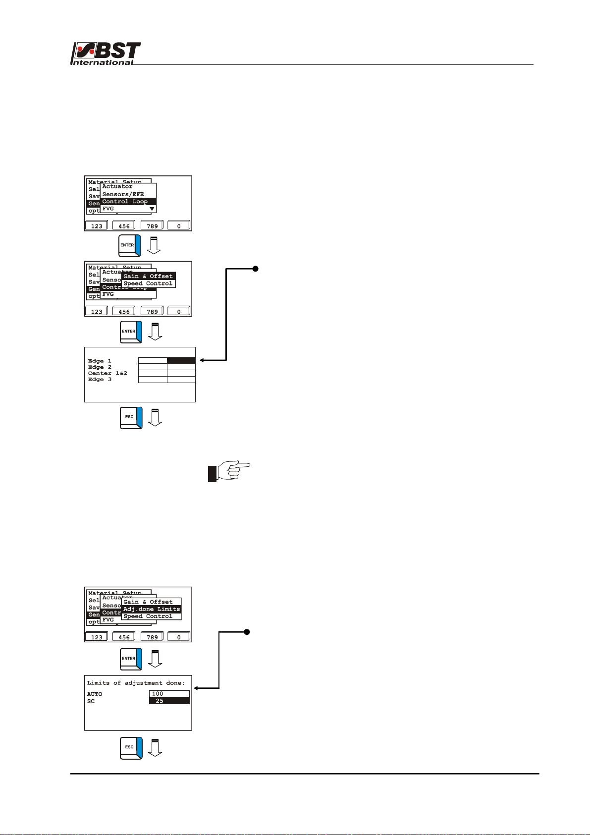
Commissioning B 3
B 3.7.5.4 Control Loop - Control loop settings
The parameters for the control circuit are set up in this sub-menu.
B 3.7.5.4.1 Gain & Offset – Amplification & setpoint values
1. Select Control Loop in General Set-up and confirm by
pressing ENTER afterwards.
2. Mark Gain & Offset in the selection window and then confirm
by pressing ENTER.
3. This will open up a window for the set point value and gain
settings.
The set value (W) for the web position and the gain setting
(XP) can be set up separately here for each of the guiding
modes.
We recommend that you should use the factory default
settings for standard controllers.
Setting range: 0 – 999.99
sens.mode W XP
0
0
0
0
5.00
5.00
5.00
5.00
4. Press the ESC button to exit the window after you have
entered the settings.
B 3.7.5.4.2 Adj. done Limits – Bearing position controlled
This function is only relevant when being used together with a
Profibus DP module for exchanging data with the customers
PLC. The corresponding protocol is Protocol 1049.
Using the specifications (notification threshold), evaluations are
made in this sub-menu as to when a new position that has been
approached is termed as controlled. This can then be used as
the start position for the following working sequence. This
notification threshold must be determined empirically and
individually for each application. You can only influence the
message and not to the controlling of the system.
1. Mark Adj.done Limits in the selection window and then
confirm by pressing ENTER.
2. Determine the values.
Note that: Larger values require an earlier message.
3. Press the ESC button to exit the window.
ekrPro Com
60
web guide controller EDV No.: MD.191.01.05/1.6.x Chapter: B 3
with analog sensors Date: 23.11.2007 Page: 37/73

Commissioning B 3
B 3.7.5.4.3 Speed Control – Speed regulation
When speed control is activated, speed variations, which can be
caused by varying loading of the actuator, are automatically
compensated.
This activation of this function is a default setting.
It must be deactivated if a tacho-generator is being used.
1. Select Speed control in the selection window and then
confirm by pressing ENTER.
2. Activate speed control using the vertical arrow keys:
3. Press the ESC button to exit the window.
(de)activate speed control
active
X
ekrPro Com
60
web guide controller EDV No.: MD.191.01.05/1.6.x Chapter: B 3
with analog sensors Date: 23.11.2007 Page: 38/73

Commissioning B 3
B 3.7.5.5 FVG –
Sensor positioning device
The control unit integrated in the controller for running the sensor
positioning device can be parameterised in this sub-menu.
A stepping motor drives the sensor adjustment unit.
The stepping motor output stages are not
short circuits.
You must check, without fail, using a suitable test unit
(ohmmeter) that no short circuits or cross-connections
between the two windings exist before starting the
commissioning.
The connection cable from the ekrPro Com
sensor adjustment unit must not exceed the maximum cable
length of 20 m.
Power is continuously applied to the stepping motor output
stage, even when stopped. Therefore any work undertaken on
the interconnections must only be carried out with the power
switched off.
The FVG function has been set to not activated in the factory, i.e.
no further settings are required if an FVG is not connected to the
system.
The required setting must be entered if the FVG function will be
used.
B 3.7.5.5.1: Connection – Activating of the sensor positioning
device (FVG) connected
1. Select FVG in General Setup and confirm by pressing ENTER
afterwards.
2. Select Connection in the selection window and then press
ENTER to open the inputting menu.
3. Select the desired operating mode from the option list.
• Not Connected:
• FVG eco:
• FVG 1MK Op.:
• FVG 2MK Op.:
Move the sensors/FVG slides manually
Sensor positioning device with stepping
Sensor positioning device with two
4. Press the ESC button to exit the inputting menu.
protected against
60
control unit to the
The sensor positioning device is
deactivated (default setting).
by means of the controller arrow keys.
motor. The FVG slides are moved by the
controller.
stepping motors. It is fitted with a hoist.
The FVG slides are moved by the
controller.
ekrPro Com
60
web guide controller EDV No.: MD.191.01.05/1.6.x Chapter: B 3
with analog sensors Date: 23.11.2007 Page: 39/73

Commissioning B 3
Once the selection has been made, specific settings must be carried
out for the FVG eco, FVG 1MK Op. and FVG 2MK Op. modes.
B 3.7.5.5.2 FVG eco
The FVG eco mode allows the sensors/FVG slides belonging to the
FVG connected to be moved using the controller arrow keys. It
effectively represents manual operation of the FVG.
For this reason, automatic edge search functions and web width
adjustment are inactive
in this mode.
The specific settings are analogue to those in the Internal FVG. The
procedure is described under point 3.7.5.5.3.
B 3.7.5.5.3 Internal FVG
The Int. FVG submenu is used when the FVG 1MK Op. mode has
been selected (normally when using a FVG 1K or FVG 1MK).
Homing Direction –
Retraction direction and limit switch assignment
The sensor’s retraction direction and the assignment of the limit
switches are set up in the next steps.
1. Mark Int. FVG in the FVG selection window and then confirm
by pressing ENTER. Select Homing Dir. from the sub-
directory and then press ENTER to open the inputting menu.
Change User
Actuator
Material Setup
Sel. Std. System
General Setup
opt. Logic
123 456 789 0
Connected
Sensors/EFE
Homing Dir.
Control Loop
Retract Mode
FVG
Err. Behaviour
2. Press the F1 key to check the selected retraction direction.
By pressing the F1 key, the FVG slide must move outwards
(into the homing position).
After the homing position is reached, the limit switch with the
outer label must be activated ( ).
Exit the window without making any changes if the homing
direction and limit switch assignment are correct.
If the FVG slide moves inwards when the F1 key is pressed,
then the checkbox Homing dir. inv. should be activated.
If the limit switch with label inner is activated in the homing
position, then the checkbox Ref. switch inv. should be
activated.
If the limit switch is activated but no checkbox
Note:
(outer or inner) is activated, then the limit switch
requires testing.
3. Press the ESC button to exit the inputting menu after you
have entered the setting.
ekrPro Com
60
web guide controller EDV No.: MD.191.01.05/1.6.x Chapter: B 3
with analog sensors Date: 23.11.2007 Page: 40/73

Commissioning B 3
(
g
The outside FVG1 limit switch has been determined as the reference
point for the FVG slide (offset = 0.0 mm)
Offset
Offset 2 (FVG)
FVG 1
Web running
direction
FVG 2
Offset 1 – position offset to FVG1 slide position
You can use the position offset to, for example, set the home
position (= 0.0 mm) to a fixed point, e.g. machine wall or a specific
point within the machine. The offset value is added to the current
FVG position, which results in the "Abs. slide pos.“
absolute position
. machine wall
e.
Fixed point in the machine
offset
Home position
[Dist. from home = 0.0 mm]
actual FVG position
Offset 2 – position offset to FVG2 slide position
The meaning of the entry and display fields is equivalent to those of
Offset 1.
2000 mm has been set as the default value for the FVG2 offset.
When carrying out initial start-up, this value must be adapted to the
actual FVG length.
If Sensor 2 moves in the opposite direction to Sensor 1, and if the
distance information is based on the same fixed point, you should
activate the Inverted checkbox.
ekrPro Com
60
web guide controller EDV No.: MD.191.01.05/1.6.x Chapter: B 3
with analog sensors Date: 23.11.2007 Page: 41/73

Commissioning B 3
Range –
Traversing range limits
The traversing range limits are entered in the menu Range.
They are the basis for displaying the traversing movement in the
operating status screen.
1. Select Range from the sub-directory and then press ENTER
to open the inputting menu.
2. Press the F1 to start the retraction of the slides to the park
position (home position). After this position has been
reached, the FVG stops.
3. Use the F2 or F3 buttons to carefully traverse the sensor in
the direction of the inner limit switch. Once the limit switch
has been reached, press key F4 (set). This completes the
adjustment procedure.
4. Press key F1 to run the sensor to the park position so that you
can draw in the web at a later point.
5. Press the ESC button to exit the inputting menu after you
have entered the settings.
If material has already been placed in the FVG adjustment range,
you can also enter the inside limit position directly into the editing
box.
If you are now working with a position offset, this does not need to
be referred to in this dialog window.
The following arises from the representation in the operating display.
The value shown gives the absolute
distance from the fixed point entered in
the offset dialog. In other words, the
position offset is included in the
numerical representation.
The relative position (bar representation) relates to
the range value entered.
In other words, the position offset is not included.
Feed – Feed for stepping motor/gearing combination
This setting is treated as the feed per motor revolution for the
stepping motor / gearing combination.
The manufacturer has entered this default setting and you are only
permitted to modify it (if necessary) after having obtained the
manufacturer’s agreement.
The relevant procedure then has to be agreed.
All warranty claims will be invalidated in any other case.
ekrPro Com
60
web guide controller EDV No.: MD.191.01.05/1.6.x Chapter: B 3
with analog sensors Date: 23.11.2007 Page: 42/73

Commissioning B 3
B 3.7.5.5.4 FVG Pro
The FVG Pro submenu is used when the FVG 2MK Op. mode has
been selected (usually when using an FVG 2MK). In this case, each
FVG needs to be adjusted separately. The terms used here FVG 1
(Slide 1) and FVG 2 (Slide 2) relate to the arrangements in
accordance with Point A 1.4.5.
The safety features are identical for both FVGs. The procedure for
FVG 1 (Slide 1) is used as the example here:
Homing Direction –
Retraction direction and limit switch assignment
The retraction direction of the sensors and the assignment of the
limit switches are set up in the next steps.
1. Mark FVG Pro in the FVG selection window and then
confirm by pressing ENTER. Select Slide 1 and confirm by
pressing ENTER.
2. Select Homing Dir. from the sub-directory and then press
ENTER to open the inputting menu.
3. Press the F1 key to check the selected retraction direction.
By pressing the F1 key, the FVG slide must move outwards
(into the homing position).
After the homing position is reached, the limit switch with the
outer label must be activated ( ).
Exit the window without making any changes if homing
direction and limit switch assignment are correct.
If the FVG slide moves inwards when the F1 key is pressed,
then the checkbox Homing dir. inv. should be activated.
If the limit switch with label inner is activated in the homing
position, then the checkbox Ref. switch inv. should be
activated.
If the limit switch is activated but no checkbox
Note:
(outer or inner) is activated, then the limit switch
requires testing.
4. Press the ESC button to exit the inputting menu after you
have entered the setting.
ekrPro Com
60
web guide controller EDV No.: MD.191.01.05/1.6.x Chapter: B 3
with analog sensors Date: 23.11.2007 Page: 43/73

Commissioning B 3
Offset –
positional offset to position of first FVG slide
You can create a reference system with an absolute reference point
using the positional offset. This reference point can, for example, be
the machine wall or another obvious point on the machine. It is also
possible to use an outer position or the centre of the FVG. If the
centre of the FVG is used, one of the FVG slides will move in a
negative direction.
The offset value is added to the current FVG position and results in
the absolute distance to this reference point (Abs. slide pos.).
The setting up of an absolute reference system is necessary for use
of the Pre-positioning function.
Example:
FVG 1
Offset FVG 1
Reference point
(zero position)
Offset FVG 2
FVG 2
Tape measure
1. Press the F1-key. The FVG slides move to the home
position.
2. Measure offset FVG1 (distance between reference point Î
centre sensor measurement window) and enter the value
under offset [mm].
3. Use the F2 and F3 buttons to traverse the FVG a short path.
FVG 1
path travelled (Dist. from home)
absolute position measured
4. Now compare the value shown under Abs. slide pos. with
the measured value.
If the measured value is larger and the displayed value
smaller, then you must activate the inverted checkbox.
5. Carry out settings for the second FVG slide (Slide 2) in the
same manner.
ekrPro Com
60
web guide controller EDV No.: MD.191.01.05/1.6.x Chapter: B 3
with analog sensors Date: 23.11.2007 Page: 44/73

Commissioning B 3
The standard operating display now shows the position of the centre
of the measurement window belonging to the appropriate sensor
based on the reference point.
Range –
Traversing range limits for first FVG slide
The traversing range limits are entered in the menu Range.
They are the basis for displaying the traversing movement in the
operating status screen.
1. Select Range from the sub-directory and then press ENTER
to open the inputting menu.
2. Press the F1 to start the movement of the slide to the park
position (home position). After this position has been
reached, the FVG stops.
3. Use the F2 or F3 buttons to carefully traverse the sensor in
the direction of the inner limit switch. Once the limit switch
has been reached, press key F4 (set). This completes the
adjustment procedure.
4. Press key F1 to move the sensor to the park position so that
you can draw in the web at a later point.
5. Press the ESC button to exit the inputting menu after you
have entered the settings.
If material has already been placed in the FVG adjustment range,
you can also enter the inside limit position directly into the editing
box.
ekrPro Com
60
web guide controller EDV No.: MD.191.01.05/1.6.x Chapter: B 3
with analog sensors Date: 23.11.2007 Page: 45/73

Commissioning B 3
Feed –
Feed for stepping motor/gearing combination
This setting is treated as the feed per motor revolution for the
stepping motor / gearing combination.
The manufacturer has entered this default setting and you are only
permitted to modify it (if necessary) after having obtained the
manufacturer’s agreement.
The relevant procedure then has to be agreed.
All warranty claims will be invalidated in any other case.
In addition to the specific settings which depend on the FVG used,
you should also carry out general settings for the FVG application in
the menu.
B 3.7.5.5.5 - Retract Mode – free-running mode
The retract mode determines when the FVG will traverse into the
park position (home position) after a specific operating mode
change.
Change User
Actuator
Material Setup
Sel. Std. System
General Setup
opt. Logic
123 456 789 0
Connected
Sensors/EFE
Homing Dir.
Control Loop
Retract Mode
FVG
Err. Behaviour
1. Select Retract Mode from the sub-directory and then press
ENTER to open the selection menu.
2. The following retract modes are available in the selection
menu:
• SC: The sensor positioning device will traverse into
the park position after switching over to the
Select a full retract mode
SC
Man.
SC & Man.
123 456 0789
SC mode
• Man.: The sensor positioning device will traverse into
the park position after switching over to the
MAN mode
• SC & Man.: The sensor positioning device will traverse into
the park position after switching over to the
SC or MAN mode.
3. Press the ESC button to exit the inputting menu after you
have made the selection.
B 3.7.5.5.6 - Norming Mode – Standardization Mode
The method for standardizing the FVG sensor can be selected in
Norming mode.
The sensor will be automatically adjusted to the material
characteristics during norming.
This will occur immediately if norming is active and the controller is
switched over to AUTO mode.
ekrPro Com
60
web guide controller EDV No.: MD.191.01.05/1.6.x Chapter: B 3
with analog sensors Date: 23.11.2007 Page: 46/73

Commissioning B 3
1. Select Norming Mode from the sub-directory and then press
ENTER to open the selection menu.
2. The following norming modes are available in the selection
menu:
• Bright:
Only a bright setting standardisation will be
carried out.
Select a norming mode
Bright
Bright/Dark
No Norming
123 456 0789
This standardisation mode is normally used
for the infrared sensor IR 2002 with
reflection bar.
• Bright/Dark:
Both bright and dark setting standardisations
will be carried out.
This standardisation mode is normally used
for infrared sensors with film material.
• No norming:
Sensor standardisation will not be carried out.
This standardisation mode is normally used
for ultrasonic sensors.
3. Press the ESC button to exit the inputting menu after you
have made the selection.
B 3.7.5.5.7 - Width Adjust – FVG operating mode for center line guiding
Use Width Adjust to select FVG operating mode for center line
guiding.
1. Select Width Adjust from the sub-directory and then press
ENTER to open the inputting menu.
2. The standard values are already entered in the settings
menu. These should be adapted in accordance with the
application.
The sensor positioning unit follows the material web if more
than the portion set in the editing box Width adj. Level [%] of
the sensor scanning area is covered.
The example setting entered her (75%) means that the sensor
will follow the material web if less than 25% or more than 75%
of the sensor scanning area is covered.
3. Press the ESC button to exit the window.
ekrPro Com
60
web guide controller EDV No.: MD.191.01.05/1.6.x Chapter: B 3
with analog sensors Date: 23.11.2007 Page: 47/73

Commissioning B 3
25% covering
Start of sensor tracking
50% covering
End position
75% covering
Start of sensor tracking
• Lvl. Outer:
The approach of the sensor towards the
material web generally occurs from the outside.
The FVG operating mode can be carried out in the MAN
mode, in the Automatic mode as well as the SC mode.
However, the change will only become effective in the
controller after the operating mode has been changed again.
If, for example, you want to change over and you are in
Automatic mode then you must change over to MAN mode
and then back to Automatic mode again. Only then will the
change become effective.
4. Press the ESC button to exit the window.
B 3.7.5.5.8 - Repositioning – repositioning of the material
after certain events
The current position of the material web is saved once an event
takes place (e.g. web tear). Once the event has been rectified, the
material is repositioned to this position. This functionality is only
effective once pre-positioning has been activated.
1. Select “Repositioning“ from the sub-menu and then press
ENTER.
2. Activate the required behaviour in the settings menu.
The web/sensor position is saved after a web tear has
occurred.
The web/sensor position is saved at the time of switching
over from Automatic operating mode to Manual or SC
operating mode.
3. Press the ESC button to exit the inputting menu after you
have made the selection.
ekrPro Com
60
web guide controller EDV No.: MD.191.01.05/1.6.x Chapter: B 3
with analog sensors Date: 23.11.2007 Page: 48/73

Commissioning B 3
B 3.7.5.5.9 - Velocities – adjustment of positioning speeds
This function can be used to adapt the positioning speeds for
various actions.
1. Select Velocities from the sub-menu and then press
ENTER.
2. The standard values are already entered in the settings
menu.
These can be accepted as is or adapted to the application.
3. Press the ESC button to exit the window.
The parameters have the following meanings:
Retract mode [mm/s]:
This parameter is used to determine the sensor positioning
device retraction speed.
Edge push vel. [mm/s]:
This parameter is used to match the traversing speed of the
sensor positioning device to the displacement speed of the
actuator. This prevents the sensor mounted on the FVG slide
from being pushed into the more slowly sideways moving
material web during edge searching during web centerline
guiding.
Slow Man. vel. [mm/s]:
Speed which should be used when shifting the material web
manually in automatic operation (for example shifting the web
using remote-control arrow keys).
Fast Man. vel. [mm/s]:
Speed which should be used when moving the FVG slides in
the Manual operating mode (for example when moving the
FVG slides using a menu dialog box keys).
This parameter is only relevant for FVG eco application.
Norm. vel. [mm/s]:
Speed which is run during norming.
ekrPro Com
60
web guide controller EDV No.: MD.191.01.05/1.6.x Chapter: B 3
with analog sensors Date: 23.11.2007 Page: 49/73

Commissioning B 3
B 3.7.5.5.10 - Special – Special settings for moving the FVG slides
during edge searching
1. Select Special from the sub-directory and then press ENTER
to open the inputting menu.
2. Standard values have already been entered.
These can be accepted as is or adapted to the application.
3. Press the ESC button to exit the window.
Mode after Error:
Operating mode which the system switches to after an error
occurs (e.g. web tear).
Sensor-cover-guarding:
This monitoring function prevents destruction of the material
web due to unwanted contact with the sensors.
If the coverage of the sensor scanning area, with the
checkbox activated, exceeds 90 % of full coverage, then the
FVG slides are automatically stopped.
This monitoring function is only active when oscillation
is activated or during sensor positioning.
ekrPro Com
60
web guide controller EDV No.: MD.191.01.05/1.6.x Chapter: B 3
with analog sensors Date: 23.11.2007 Page: 50/73

Commissioning B 3
B 3.7.5.6 Width Measure - Web width measurement
The parameters required when using a width-measuring unit are set
up in this sub-menu.
B 3.7.5.6.1 Ref. Width – Width of the calibration sheet
A piece of material with a known width must be used once as a
reference for adjusting the web width measurement.
1. Select Width Measure in General Set-up and confirm by
pressing ENTER afterwards.
2. Ref. Width is marked in the following selection window. Press
the ENTER button to call up the inputting window.
3. Insert calibration sheet and start width measurement. To do
this you must switch over to centerline guiding and then
select Automatic operating mode.
Width Measure Offset
current width:
enter ref.width
mm
.0
set ref
4. Enter the width under enter ref. width after the sensors have
reached the edges of the calibration sheet and press the F3
button to take over the entered value.
5. The adjustment procedure is finished.
The actual measured value (current width) and the entered
reference value (ref. width) must both show the same size.
6. Press the ESC button to exit the window.
The reference width value last entered remains saved when the
device is switched off.
Inserting the calibration sheet:
First check the dimensions of the calibration sheet.
Important:
The calibration sheet reference dimension can change marginally
due to the effects of heat. Information relating to various
temperatures is given on the calibration sheet.
To obtain the best results, use the reference dimension for the
temperature which is nearest to the actual temperature, or
interpolate the dimension between these two temperatures.
ekrPro Com
60
web guide controller EDV No.: MD.191.01.05/1.6.x Chapter: B 3
with analog sensors Date: 23.11.2007 Page: 51/73

Commissioning B 3
B 3.7.5.6.2 Limits – Set width, error and warning limits
The set value for the web width (Nominal Width) is entered in this
window. The lower and upper error limits (E+, E-) and the lower and
upper warning limits (W+, W-) are also set up here. The measuring
unit is mm.
These are the entries which form the basis for the operating display
when the web width measurement is active.
Five conditions are indicated.
a) Material width is in valid range.
b) Material width is too wide when related to the upper warning
limit;
it lies in the W+ area (24V DC at output 66).
W+
c) Material width is too small when related to the lower warning
limit;
it lies in the W- area (24V DC at output 65).
W-
d) The material width lies outside the absolute tolerance.
It lies in the error limit areas E+ (24 VDC at output 66)
E+
e) The material width lies outside the absolute tolerance.
It lies in the error limit areas E- (24 VDC at output 65)
E-
Digital message outputs are available for the limits.
The meaning and allocation of messages relating to digital
outputs are described under Point B 3.7.5.9.2.
Material width
Material width
Material width
Material width
ekrPro Com
with analog sensors Date: 23.11.2007 Page: 52/73
60
web guide controller EDV No.: MD.191.01.05/1.6.x Chapter: B 3

Commissioning B 3
1. Select Limits in the selection window and press the ENTER
key. This will open up the input window.
2. Enter the nominal value for the material width in the edit field
Nominal Width.
3. Enter selected values for the error and warning limits in the
80.0
-5.0
5.0
-2.0
2.0
corresponding edit fields.
4. Press the ESC button to exit the window after you have
entered the settings.
B 3.7.5.6.3 Opmodes – Operating modes in which the
width measurement should be active
You can use this window to determine in which operating modes the
width measurement is able to be implemented.
This makes it also possible to carry out a web width measurement
without an FVG if the checkbox has been activated for the
corresponding operating mode.
If an FVG is connected, the condition is that retraction has been
deactivated for the selected operating mode(s).
1. Mark Opmodes in the selection window and then press the
ENTER button. This will open up the input window.
2. Select the desired mode(s).
3. Press the ESC button to exit the window after you have
entered the settings.
ekrPro Com
60
web guide controller EDV No.: MD.191.01.05/1.6.x Chapter: B 3
with analog sensors Date: 23.11.2007 Page: 53/73

Commissioning B 3
B 3.7.5.7 Edge Sources - Assignment of the sensors
to the scanning modes
The ekrPro Com
60
controller allows the free assignment of the
connected sensors to different scanning modes.
Therefore each scanning mode can have the input signal of any
sensor allocated to it. For example, it is possible to assign the
"sensor right" sample mode selection key to the sensor connected
as "sensor left".
If the controller is operated via a CAN bus, the scanning modes can
also be assigned to the input signals of sensors which are
connected to another controller of the BUS-system.
1. Select Edge Sources in General Setup and confirm by
pressing ENTER afterwards.
2. A sample type selection window opens.
The following selection types can be selected:
Guiding
Control input Key
Mode
Edge 1
Edge 2
Edge 3
Src. SC
Edge 1
Edge 2
Edge 3 (contrast transition)
Centre position control
encoder
Src. EFE
Electronic remote fine
—
adjustment unit
3. Select sample mode using the vertical arrow keys and press
ENTER.
4. The input window appears for the selected sample mode.
5. If the selected sample mode is to be assigned to the input
signal of a sensor that is connected to another CAN bus unit,
then select the option list device and press the ENTER key to
open it.
All the units connected to the CAN bus are displayed in the
opened option list.
6. Select the desired CAN bus unit and press ENTER.
7. Select the option list edge using the horizontal arrow keys and
press ENTER.
8. Select the sensor from the option list to whose input signal the
selected sample mode is to be assigned and press ENTER.
ekrPro Com
60
web guide controller EDV No.: MD.191.01.05/1.6.x Chapter: B 3
with analog sensors Date: 23.11.2007 Page: 54/73

Commissioning B 3
9. The input value supplied by the selected sensor can be shown
in this window as either an absolute or normalized
(percentage) value.
To activate normalized display, select checkbox norm..
10. If necessary, the checkbox inv. is used to invert the input
signal delivered by the sensor.
Inverting is necessary, if the input value delivered by the
sensor changes in the wrong direction when material is
brought into the sensor measurement area.
11. Use the function keys F2 and F3 to drive the actuator in
Manual operating mode.
This enables checking of the change in the sensor signal with
an inserted material web.
12. Press the ESC button to exit the window.
ekrPro Com
60
web guide controller EDV No.: MD.191.01.05/1.6.x Chapter: B 3
with analog sensors Date: 23.11.2007 Page: 55/73

Commissioning B 3
B 3.7.5.8 Add. Functions – Special function
Explanations for the requirements and function of both special
functions can be obtained under point 3.5.8. The parameter settings
are carried out as follows:
B 3.7.5.8.1 Tear Off Det. – Tear Off Detection
Setting of the parameters for the function Tear-off detection is
made separately for each guiding mode. If necessary, a different
sensor can be allocated as the tear-off detection sensor for each
guiding mode. It is also possible to allocate two different guiding
modes with different parameters to a single sensor.
1. Select Add. Functions in General Setup and then select the
Tear Off Det. sub-directory afterwards.
Confirm the respective selection by pressing ENTER.
2. Select the desired guiding mode (Edge 1, Edge 2, Edge 3,
Center 1&2) from the option list.
Confirm the selection by pressing ENTER.
3. This will open up the inputting window for the selected guiding
mode. The following separate parameters can be set:
► Sensor:
Selection of the sensor with which tear-
off detection is to be implemented.
► threshold [%]: Percentage covering of the sensor
measuring band, above which a change
is detected as a tear.
For the example value entered here
(80/20), this means that the function
detects a tear, if more than 80% or less
than 20% of the sensor measuring band
is covered.
► sig. chg. limit. [%/4ms]: Maximum permissible rate of
change of the sensor signal in %
per 4 ms
(Scanning cycle = 4 ms, i.e. the
sensor measurements are read
every 4 ms).
A tear is detected, if the rate of
change of the sensor signal
exceeds the percentage per 4 ms
set here.
The values to be set are
calculated according to the
formula on the following page.
► delay [ms]: Delay time in ms from detection of a tear
until blocking of the guiding system.
► hold [ms]:
Blocking hold time in ms after the
detected end of the tear until the blocking
is lifted, i.e. until the guiding system is
activated.
ekrPro Com
60
web guide controller EDV No.: MD.191.01.05/1.6.x Chapter: B 3
with analog sensors Date: 23.11.2007 Page: 56/73

Commissioning B 3
4. If necessary, set parameters for further guiding modes
(see points 2 and 3).
5. Press the ESC button to exit the window.
B 3.7.5.8.2 Oscillation
This special function enables the position of the web of material to
be displaced within the sensor´s visual range using adjustable
amplitude (size of the lateral displacement) and frequencies
(displacement speed).
The format of the web displacement when the controller is operated
without a sensor positioning device follows a delta curve ( ).
When operated with a sensor positioning device, a sine-wave ( )
web displacement takes place. See also chapter A1, Point A 1.4.4‚
Oscillation types and curves’.
Osc. Mode – determine operating mode for oscillation mode
1. Select Add. Functions in General Setup and then select the
„Osc. Mode“ sub-directory afterwards.
Confirm the respective selection by pressing ENTER.
2. The set value for the web width (Nominal Width) is entered in
this window. Activation then takes place in the operating
status display using the F1 key.
The following settings are possible:
• • OFF:
Oscillation is deactivated
(factory setting)
• Auto:
Activation in operating mode
Automatic
Repositioning of material web is
carried out within the sensor visual
area with adjustable amplitude.
• SC:
Activation in operating mode SC
using the servo-center component.
• FVG Auto:
Oscillation with connected FVG
An FVG oscillation with sine-shaped
web repositioning.
3. Press the ESC button to exit the window.
ekrPro Com
60
web guide controller EDV No.: MD.191.01.05/1.6.x Chapter: B 3
with analog sensors Date: 23.11.2007 Page: 57/73

Commissioning B 3
Osc. Params. – Set oscillation parameters
The oscillation parameters, i.e. amplitude and frequency, are
set in this submenu.
1. The Osc. Params submenu Select Sensor 1 and confirm by
pressing ENTER.
2. The parameters have the following meanings:
► Amplit. Auto [%]:
Amplitude of the oscillation in operating
mode Automatic.
The percentage value relates to the size
of the sensor scanning area.
Setting range: 1 % to 99 %
► Amplit. SC [%]:
Setting up the amplitude for the SC
operating mode
The percentage wise input of the
amplitude relates to the distance
between the software limit switches.
One limit switch represents 0 % and the
other 100 %.
Setting range: 1 % to 99 %
► Amplit. FVG [mm]
Amplitude of oscillation when using a
sensor positioning device.
The sample value shown here of
10 mm results in repositioning of the
web by ± 5 mm.
Setting range: 0 to 999.9 mm
► Frequency [Hz]:
Oscillation frequency.
Setting range: 0.016 … 1.000 Hz
3. Press the ESC button to exit the window.
ekrPro Com
60
web guide controller EDV No.: MD.191.01.05/1.6.x Chapter: B 3
with analog sensors Date: 23.11.2007 Page: 58/73

Commissioning B 3
B 3.7.5.9 Dig. IO Config. - Configuration of the
digital inputs and outputs
B 3.7.5.9.1 Configure –
selection of digital input table and activation of inputs/outputs
You can select from two tables in this dialog window. Both
contain various assignments for the digital inputs (see Point
B 3.7.5.9.3).
The tables are created so that they cover most of the
applications controllable using digital inputs, which helps
avoid time-consuming configurations.
Specific adjustments can, however, still be carried out if
required.
The procedure is described under Point B 3.7.5.9.2.
1. Select Dig. IO in General Setup and then select the
Configure sub-directory afterwards.
Confirm the respective selection by pressing ENTER.
2. Select the required input table. The Dig.In Table 1
(Default Table) and Dig.In Table 2 (Special Shifted
Center) tables are available for selection.
The input assignment for each table is represented in
Point B 3.7.5.9.3. Confirm the selection with the F2 (Set.)
key.
3. Press the ESC button to exit the window.
Both digital inputs and outputs can be switched off for initial
startup. Please deactivate the appropriate checkboxes to do
this.
Attention!
Any activated Ext.Lock functionality will be
cancelled by deactivating the IN ena. checkbox.
Thus, the actuator can carry out positioning
movements.
The controller release is, however, not
influenced.
B 3.7.5.9.2 Inputs –
Digital inputs
When necessary this sub-menu permits changing of the assignment
of various functions to the digital inputs of the controller. Moreover
the respective signal pattern (bit mask), which must be applied to the
digital inputs (terminals 74 – 85) in order to activate a particular
function, can be changed.
The procedure for changing the factory-set standard configurations
of the digital inputs is explained in the following two examples,
based on the Dig.In Table 1 (Default Table).
ekrPro Com
60
web guide controller EDV No.: MD.191.01.05/1.6.x Chapter: B 3
with analog sensors Date: 23.11.2007 Page: 59/73

Commissioning B 3
Example 1: The function Tear-off detection is to be assigned to
the digital inputs (lines 29 and 30).
In so doing, the standard bit-pattern for lines 29 and
30 must not
be changed.
1. Select Dig. IO in General Setup and then select the
Inputs sub-directory afterwards.
Confirm the respective selection by pressing ENTER.
2. The digital inputs setting window opens.
Truth Tabl e Pattern
no. assigned function
29 Keyb.Lock ON
Bitmask
85 74
1
deact.
Ln
Ln
3. Use the function keys F1 (next row) or F2 (previous line) to
select the stored truth table.
The option list displays the factory assigned function (Keyb.
Lock ON) for row 29.
Truth Tabl e Pattern
no. assigned function
29 Tear Out ON
Bitmask
85 74
1
deact.
Ln
Ln
4. Select the option list using the horizontal arrow keys and open
by pressing ENTER.
The option list contains all the available functions.
5. Select the function Tear Out ON (tear-off detection ON) using
the vertical arrow keys and press ENTER.
Truth Tabl e Pattern
no. assigned function
30 Keyb.Lock OFF
Bitmask
85 74
0
deact.
Ln
Ln
6. Select line 30 using function key F2.
The option list displays the factory assigned function ("Keyb.
Lock OFF) for line 30.
7. Select the option list using the horizontal arrow keys and open
Truth Tabl e Pattern
no. assigned function
30 Tear Out OFF
Bitmask
85 74
0
deact.
Ln
Ln
by pressing ENTER.
8. Select the function Tear Out OFF (tear-off detection OFF)
using the vertical arrow keys and press ENTER.
Assignment of the function Tear-off detection to the digital
inputs is now completed.
9. Press the ESC button to exit the window.
By pressing function key F3 (deact.) within the menu, all
bits of the selected bit pattern are set to “1”.
ekrPro Com
60
web guide controller EDV No.: MD.191.01.05/1.6.x Chapter: B 3
with analog sensors Date: 23.11.2007 Page: 60/73

Commissioning B 3
Example 2: The function Tear-off detection is to be assigned to
the digital inputs (lines 21 and 22).
The following section of the truth table shows that lines 21 and 22
belong to a bit-block with a total of 8 lines (lines 21 to 28).
Factory allocation of functions
with the corresponding standard bit-patterns
Terminal
Line
Significance
20 FVG stop X X X 1 1 1 X X X X X X
21 Set Lim.Sw. 1 X
22 Reset Lim.Sw. 1 X
23 Reset Lim.Sw. 1 X
24 Set Lim.Sw. 2 X
25 Reset Lim.Sw. 2 X
26 Reset Lim.Sw. 2 X
27 Set Overtemp. X
28 Reset Overtemp. X
29 Keyb.Lock ON 1 X X X X X X X X X X X
85 84 83 82 81 80 79 78 77 76 75 74
1 0
0 0
1 1
0 1
0 0
1 1
1 1
0 0
X X X X X X X X X
X X X X X X X X X
X X X X X X X X X
X X X X X X X X X
X X X X X X X X X
X X X X X X X X X
X X X X X X X X X
X X X X X X X X X
User defined allocations -
function Tear-off detection on lines 21 and 22
Terminal
Line
Significance
20 dig. Left/Right Stop X X X 1 1 1 X X X X X X
21
Tear Out ON
22
Tear Out OFF
23 Do Nothing 1
24 Do Nothing 1
25 Do Nothing 1
26 Do Nothing 1
27 Do Nothing 1
28 Do Nothing 1
29 Keyb.Lock ON 1 X X X X X X X X X X X
85 84 83 82 81 80 79 78 77 76 75 74
X
1 X
X
0 X
1 1
1 1
1 1
1 1
1 1
1 1
X X X X X X X X X
X X X X X X X X X
1 1 1 1 1 1 1 1 1
1 1 1 1 1 1 1 1 1
1 1 1 1 1 1 1 1 1
1 1 1 1 1 1 1 1 1
1 1 1 1 1 1 1 1 1
1 1 1 1 1 1 1 1 1
The procedure for changing the allocations can be divided into three
steps, which are described on the following page.
ekrPro Com
60
web guide controller EDV No.: MD.191.01.05/1.6.x Chapter: B 3
with analog sensors Date: 23.11.2007 Page: 61/73

Commissioning B 3
Step 1: Cancel the factory allocations of functions.
As the function tear-off detection requires only lines 21
and 22 of the bit block, the factory-side allocation of
functions to the remaining lines of the block (lines 23 to
28) must be cancelled.
Accordingly the function Do Nothing is allocated to lines
23 to 28 from the option list.
The procedure for doing this is described in example 1.
Moreover the values of all bits in the non-required lines
19 to 24 must be set to “1”.
Procedure:
1. Use the function keys F1 and F2 to sequentially
select the individual block lines.
2. Use the horizontal arrow keys to the change the bit
pattern (Bitmask) display.
3. Sequentially select the individual bits using the
horizontal arrow keys and use the vertical arrow
keys to set the value of the selected bit to “1”. The
values of all 12 bits must be set to "1”.
Step 2: Assign new function
The function Tear Out ON (tear-off detection ON) is
assigned to the line 21 and the function Tear Out OFF
(tear-off detection OFF) is assigned to the line 22.
The procedure for doing this is described in example 1.
Step 3: Adjust bit pattern
In line 21 the bit for terminal 84 is assigned the value ”1“
(24 V signal applied to terminal 84).
In line 22 the bit for terminal 84 is assigned the value ”0“
(0 V signal applied to terminal 84).
The value for all the non-relevant bits (terminal 83) of the
two lines 21 and 22 must be set to the value "X"
(not relevant).
The procedure for changing the bit values is described in
step 1.
ekrPro Com
60
web guide controller EDV No.: MD.191.01.05/1.6.x Chapter: B 3
with analog sensors Date: 23.11.2007 Page: 62/73

Commissioning B 3
B 3.7.5.9.3 Truth table
Default values for digital input allocation: Dig. InTable 1
Terminal
Line Significance 85 84 83 82 81 80 79 78 77 76 75 74
1 set Auto
(automatic mode)
2 set MAN
(manual mode)
3 set SC
(servo center position)
4 opmode clear
(defined zero state operating mode)
5 set Edge1
(edge 1)
6 set Edge2
(edge 2)
7 set Center1&2
(center 1/2)
8 set Edge3
(edge 3)
9 set Edge3 Inv. (inverse edge 3)
10 guid.mode clear
(defined zero state guiding mode)
11 Motor stop
12 Motor stop
13 FVG stop
14 FVG stop
15 Motor left
16 FVG left
17 Motor right
18 FVG right
19 Motor stop
20 FVG stop
21 Set Lim.Sw. 1
(stop switch 1)
22 Reset Lim.Sw. 1
(reset stop switch 1)
23 Reset Lim.Sw. 1
(reset stop switch 1)
24 Set Lim.Sw. 2
(stop switch 2)
X X X X X X X X X
X X X X X X X X X
X X X X X X X X X
X X X X X X X X X
X X X X X X
X X X X X X
X X X X X X
X X X X X X
X X X X X X
X X X X X X
X X X
X X X
X X X
X X X
X X X
X X X
X X X
X X X
X X X
X X X
X
1 0
X
0 0
X
1 1
X
0 1
0 0 0
0 0 1
0 0 0
0 0 1
0 1 0
0 1 1
1 0 0
1 0 1
1 1 0
1 1 1
X X X X X X X X X
X X X X X X X X X
X X X X X X X X X
X X X X X X X X X
0 0 1
0 1 0
0 1 1
1 0 0
1 0 1
0 0 0
X X X X X X
X X X X X X
X X X X X X
X X X X X X
X X X X X X
X X X X X X
X X X X X X
X X X X X X
X X X X X X
X X X X X X
1 0 0
0 0 1
0 1 0
0 0 0
X X X
X X X
X X X
X X X
X X X
X X X
ekrPro Com
60
web guide controller EDV No.: MD.191.01.05/1.6.x Chapter: B 3
with analog sensors Date: 23.11.2007 Page: 63/73

Commissioning B 3
Terminal
Line Significance 85 84 83 82 81 80 79 78 77 76 75 74
25 Reset Lim.Sw. 2
(reset stop switch 2)
26 Reset Lim.Sw. 2
(reset stop switch 2)
27 Set Overtemp.
(over-temperature)
28 Reset Overtemp.
(reset over-temperature)
29 Keyb.Lock ON
(keyboard interlock on)
30 Keyb.Lock OFF
(keyboard interlock off)
31 -
60
Do Nothing
(reserved)
X
0 0
X
1 1
X
1 1
X
0 0
X X X X X X X X X X X
1
X X X X X X X X X X X
0
1 1 1 1 1 1 1 1 1 1 1 1
X X X X X X X X X
X X X X X X X X X
X X X X X X X X X
X X X X X X X X X
Alternative digital input allocation: see Dig. In Table 2:
Terminal
Line Significance 85 84 83 82 81 80 79 78 77 76 75 74
1 set Auto
(automatic mode)
2 set MAN
(manual mode)
3 set SC
(servo center position)
4 opmode clear
(defined zero state operating mode)
5 set Edge1
(edge 1)
6 set Edge2
(edge 2)
7 set Center1&2
(center 1/2)
8 set Edge3
(edge 3)
9 set Edge3 Inv. (inverse edge 3)
10 guid.mode clear
(defined zero state guiding mode)
11 Shifted Center OFF
12 Reset Prepos. Center
(reset pre-positioning to centre)
13 Shifted Center ON
14 Set Prepos. Center
(pre-positioning to centre)
15 set Center1&2
(center 1/2)
16 FVG left
17 FVG right
18 FVG stop
19 FVG stop
X X X X X X X X X
X X X X X X X X X
X X X X X X X X X
X X X X X X X X X
X X X X X
X X X X X
X X X X X X
X X X X X X
X X X X X X
X X X X X X
X X X X X
X X X X X
X X X
X X X
X X X
X X X
X X X
X X X
X X X
X X
X X
X X
0 1
1 0
1 1
0 0
0 0 0 1
0 0 1 0
0 1 1
1 0 0
1 0 1
0 0 0
X X X X X X
0
X X X X X X
1
1
X X X X X X
X X X X X X
0
X X X X X X
1
X X X X X X X
X X X X X X X
X X X X X X X
X X X X X X X
1 0 0
0 0 1
0 1 0
0 0 0
X X X
X X X
X X X
X X X
X X X
X X X
ekrPro Com
60
web guide controller EDV No.: MD.191.01.05/1.6.x Chapter: B 3
with analog sensors Date: 23.11.2007 Page: 64/73

Commissioning B 3
Terminal
Line Signification 85 84 83 82 81 80 79 78 77 76 75 74
20 Set limit switch 1 X
21 Reset Lim.Sw. 1
22
Reset Lim.Sw. 1
23 Set Lim.Sw. 2
24
Reset Lim.Sw. 2
25
Reset Lim.Sw. 2
26
Set Overtemp.
27
Reset Overtemp.
28
Ext. Unlock
29
Ext. lock
30 -
60
Do Nothing
(reserved)
1 0
X
0 0
X
1 1
X
0 1
X
0 0
X
1 1
X
1 1
X
0 0
X X X X X X X X X X X
1
X X X X X X X X X X X
0
1 1 1 1 1 1 1 1 1 1 1 1
X X X X X X X X X
X X X X X X X X X
X X X X X X X X X
X X X X X X X X X
X X X X X X X X X
X X X X X X X X X
X X X X X X X X X
X X X X X X X X X
0 = 0 V signal 1 = 24 V signal X = not relevant
Controller interlock
The controller interlock is generally activated. The function can only
be deactivated by application of a "1” signal (24 V=) to terminal 53.
If the controller block is activated, the output of the output stage is
switched off.
The actuator will not carry out any guiding movements.
This is valid for all
operating or guiding modes (AUTO, MAN, SC).
Keyboard interlock
All of the controller’s keys are locked by a “1“ (24 VDC) on
terminal 85. The controller can be controlled via the keyboard when
this signal is no longer set.
The individual lines in the truth table can each be allocated the
following meaning:
Significance
• Do Nothing
• set AUTO
• set MAN
• set SC
• opmode clear
• set Edge 1
• set Edge 2
• set Center 1&2
• set Edge 3
• set Edge 3 inv.
• guid. mode clear
Significance
• Motor Left
• Motor Right
• Motor Stop
• FVG Left
• FVG Right
• FVG Stop
• Set Lim.sw. 1
• Reset Lim.sw. 1
• Set Lim.sw. 2
• Reset lim.sw. 2
• Set Overtemp.
Significance Significance
• Reset Overtemp.
• Keyb. Lock ON
• Keyb. Lock OFF
• Osc. ON
• Osc. OFF
• Tear Out ON
• Tear Out OFF
• ext. Lock
• ext. Unlock
• Set W.
• Set Prepos. E1
• Reset Prepos. E1
• Set Prepos. E2
• Reset Prepos. E2
• Set Prepos. C1&2
• Reset Prepos. C1&2
• Set Prepos. Center
• Reset Prepos.
Center
• Copy cur.pos. to
Prepos.
ekrPro Com
60
web guide controller EDV No.: MD.191.01.05/1.6.x Chapter: B 3
with analog sensors Date: 23.11.2007 Page: 65/73
 Loading...