

Page 1

Soundweb 3088 Installation Guide
3088
Signal Processor
Installation Guide
1
Page 2
Soundweb 3088 Installation Guide
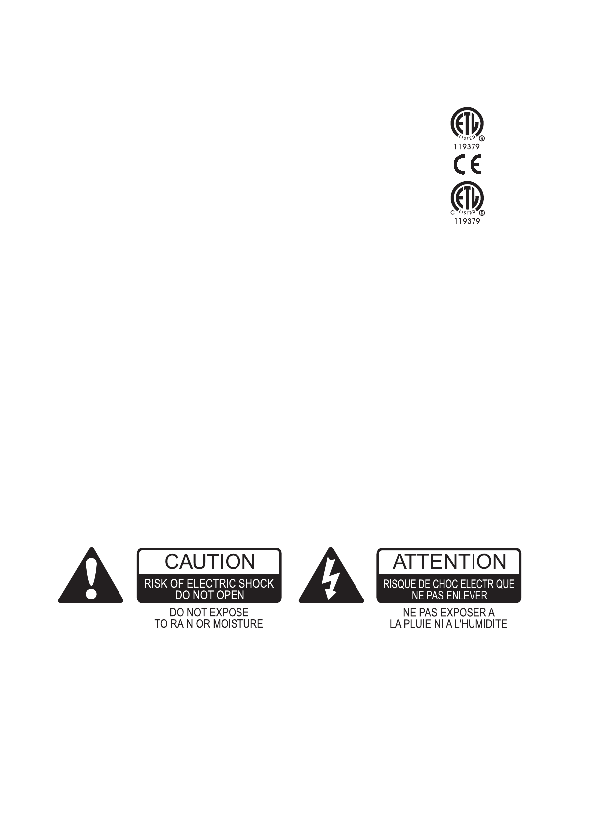
Important Safety Information - Read this carefully
This equipment has been tested and found to comply with the following
European and international Standards for Electromagnetic Compatibility and
Electrical Safety:
Radiated Emissions (EU): EN55013 (1996)
RF Immunity (EU): EN55013-2 (1996)
Electrical Safety (EU): EN60065 (1998)
Electrical Safety (USA): UL6500/ETL (2000)
Electrical Safety (CAN): CAN/CSA-E60065-00 (1994)
Before using the apparatus, read these instructions. Follow all instructions, heed them
and keep them in a safe place.
* Clean only with a dry cloth.
* Do not block any of the ventilation openings. Install in accordance with the manufac-
turers instructions.
* Do not place objects filled with liquid on this apparatus.
* Do not defeat the safety purpose of the grounding type plug. A grounding plug has two
blades and a third grounding prong. The third prong is provided for your safety. When
the provided plug does not fit into your outlet, consult an electrician for replacement
of the obsolete outlet.
* Protect the power cord from being walked upon or pinched, particularly at plugs,
convenience receptacles and the point where they exit from the apparatus.
* Only use attachments/accessories specified by the manufacturer.
* Unplug this apparatus during lightning storms or when not in use for a long time.
WARNING - TO REDUCE THE RISK OF FIRE OR SHOCK, DO NOT EXPOSE THIS
APPARATUS TO RAIN OR MOISTURE.
DO NOT REMOVE COVERS. NO USER SERVICEABLE PARTS INSIDE - REFER
SERVICING TO QUALIFIED SERVICE PERSONNEL.
THIS EQUIPMENT MUST BE EARTHED.
IT SHOULD NOT BE NECESSARY TO REMOVE ANY PROTECTIVE EARTH OR SIGNAL
CABLE SHIELD CONNECTIONS TO PREVENT GROUND LOOPS. ANY SUCH
DISCONNECTIONS ARE OUTSIDE THE RECOMMENDED PRACTICE OF BSS AUDIO
AND WILL RENDER THE EMC OR SAFETY CERTIFICATION VOID.
For continued compliance with international EMC regulations, it is important that all
cables be screened, and connected as follows:
Audio cable screens to their 3088 connector ground.
Control cable screens to the ground screws adjacent to the connector.
2
Page 3
Soundweb 3088 Installation Guide
Mechanical Installation
If the unit is likely to undergo extreme vibration through extensive road trucking and
touring, it must be supported at the rear and/or sides to lessen the stress on the front
mounting flange. Use either a ready-built rack tray or mount the 3088 unit between other
units. Damage caused by insufficient support is not covered by the warranty.
To prevent cosmetic damage to the front panel finish, use protective plastic cups under the
rack mounting bolts.
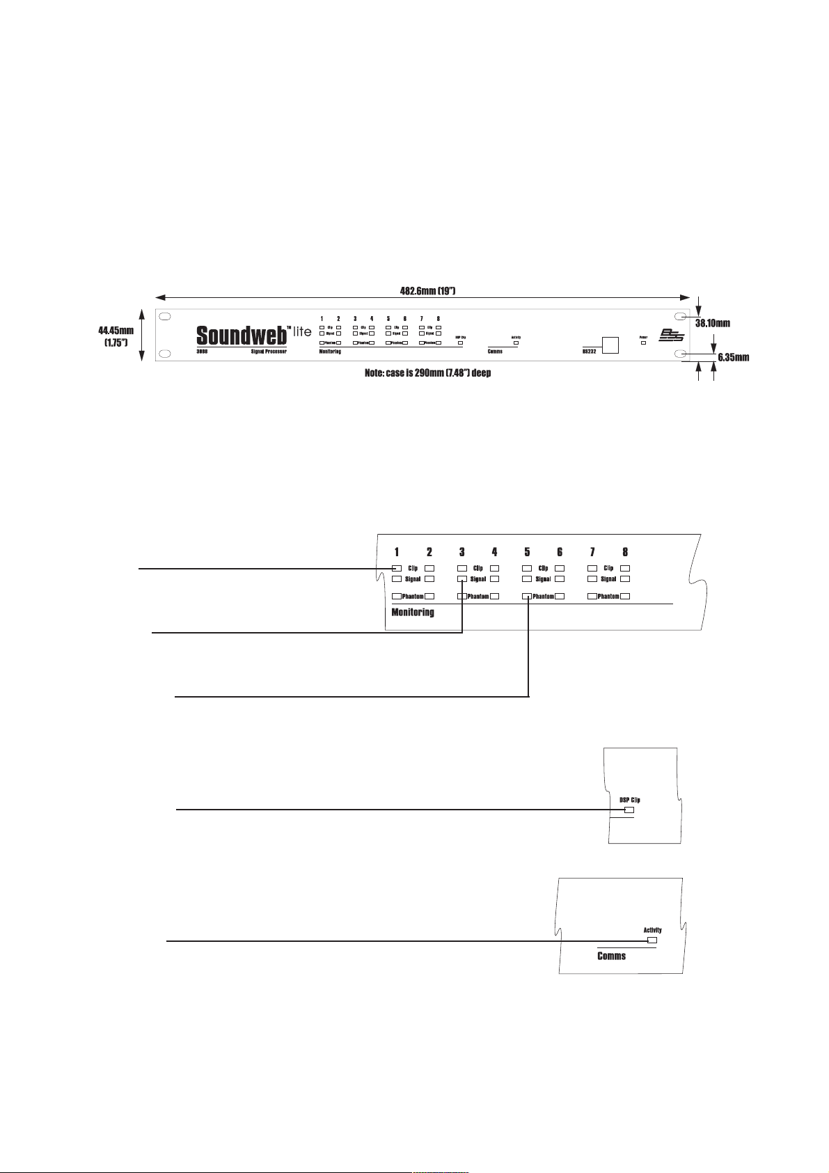
Front Panel LED Functions
Input Monltorlng
Each channel has 3 LED indicators showing:
Clip
Illuminated = excessive signal level.
Signal
Illuminated = signal is present on this channel input.
Phantom
Illuminated = phantom power is active for this Mic channel.
Scrolling from right to left = recovery mode, the device's firmware
needs reloading.
DSP Clip
Illuminated = indicates that the processed signal is clipping internally.
Comms
Activity
Flashing Yellow =indicates data transfer. The flashing is not
regular, but is dependent on the rate of transfer.
Flashing Red = indicates bad data.
3
Page 4
Soundweb 3088 Installation Guide
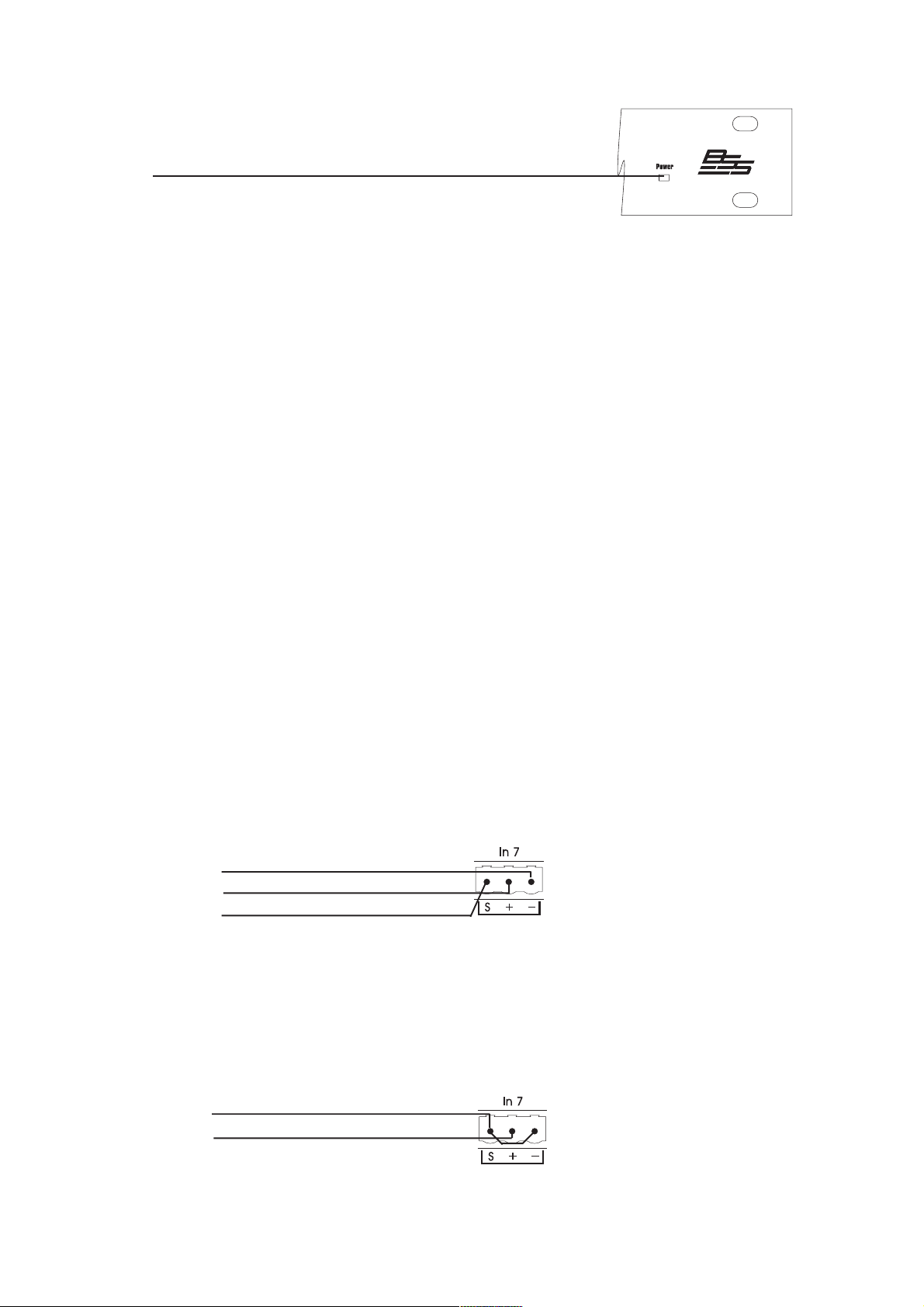
Power
illuminated = indicates that the power supply is functioning.
Rear Panel Details
Audio & Control connectors
3088 audio and control connections are via Klippon (also known as BL, Phoenix or
Combicon) pluggable terminal block connectors.
12 x 6-way female Klippon connectors are supplied for making these connections.
For audio and network cables and looms, see the Product Overview catalogue from:
Direct Cable Systems Ltd.
Tel: (020) 7485 0899 www.directcable.co.uk
Neutricon-Neutricon tour grade network cable. P/N 1 50001
Phoenix-XLR audio cable P/N 1 00521
Audio & AES/EBU Input and Output wiring convention
Soundweb products provide cable shielding back from the destination to eliminate
ground loop problems. Therefore, the shield (S) connection on an input is grounded,
whereas the shield connection on an output is floating (although connected via an
internal network to ground for EMC compliance).
Balanced wiring - The convention for balanced wiring (2-core plus shield) is:
Balanced connection 3088 connection
Pin 3 : Cold -
Pin 2 : Hot +
Pin 1 : Shield
This wiring can also be applied to the AES digital interface card.
Unbalanced wiring (analogue audio only) - The convention for unbalanced wiring to the
inputs (1-core plus shield) is:
Unbalanced connection 3088 connection
Pin 1 : Shield
Pin 2 : Hot +
Pin 3 : Link to Pin 1 (Optional for 3088 inputs)
4
Page 5

Soundweb 3088 Installation Guide
Mains inlet
IEC power connector, for connection to mains supply (100-270V AC, 50/60Hz).
Mains fuse holder
Requires a 20mm T1AL type fuse. Do not replace with anything other than the
recommended fuse.
Aux. RS232
An alternative connection for a control PC, modem or AMX/Crestron type panel. This port
works at up to 115200bps. Note that AMX panels only currently connect at 38400bps.
Pinouts
1 -DCD 6-DSR
2-RX 7-RTS
3-TX 8-CTS
4-DTR 9-N/C
5-GROUND
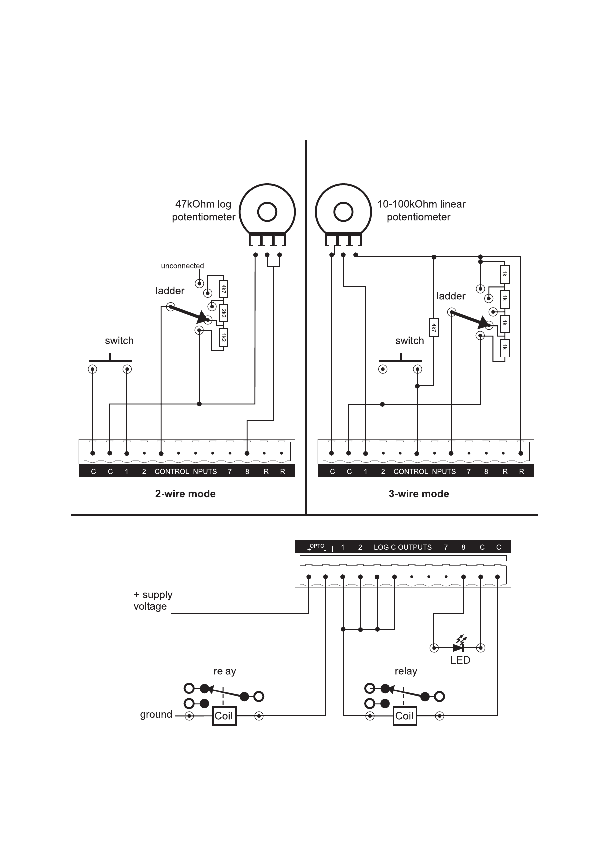
Control Inputs
Used to connect switches or potentiometers, e.g. 9012 selector wallplate (Part no.
Z-SW9012). Looking at the control port connector (on the back of the unit), there are two
common (ground) connections C to the left of the eight CONTROL INPUTS and, two
software assignable reference voltage outputs R to the right.
The control ports now have two modes of operation. In Soundweb Designers Control
Ports window these are labelled 2-wire and 3-wire.
2-wire mode
In this mode the eight CONTROL INPUTS are internally pulled up to +5V DC via a
4.7kOhm resistor. Therefore, no external voltage source is needed to create contact
closure to ground for switches such as mute buttons or, resistance to ground (for other
multi-state or continuous controls such as Parameter Presets or faders).
See the Soundweb Designer help for a table of resistor values for use with Parameter
Presets or source selectors.
Two common ground connections are provided using the two C connectors to the left
of the CONTROL INPUTS.
A 47kOhm-log potentiometer (Part no. DM10018) connected between a control input and
common will allow parameters to be controlled linearly.
3-wire mode
This mode allows the use of linear pots or faders for continuous controls. A pot would be
wired as a potential divider with the top of the track connected to the reference output
R, the wiper to a control input and the bottom of the track to a common C. For good
5
Page 6

Soundweb 3088 Installation Guide
performance pots with track resistance between 10 and 100kOhms are recommended.
Logic Outputs
Used to connect tally indicator LEDs or relays.
There are eight standard LOGIC OUTPUTS which produce 0V or +5V DC via an internal
440 Ohm resistor and two internally connected common (ground) connections C.
An LED connected between one output (Anode, A) and common (Cathode, K) will
illuminate when the logic output is activated, without requiring any external current
limiting resistor.
A high sensitivity relay (such as a reed relay) may be driven by connecting four outputs in
parallel. This arrangement will develop 4V across a 500Ohm coil, providing that all four
outputs are made logic 1 simultaneously.
OPTO Output
In addition to the eight standard logic outputs, there is an isolated output, which fails safe
(open circuit) if the unit becomes faulty.
This is effectively the collector-emitter of a transistor (which may be thought of as a
switch), in series with a 220-Ohm protection resistor. In conjunction with an external DC
power source (max 80V), this may be used to drive various loads such as relays.
6
Page 7
Soundweb 3088 Installation Guide
Control Inputs and Logic Outputs connection diagram
7
Page 8

Soundweb 3088 Installation Guide
Technical Specifications
General
DSP capability 200MIPS (Million Instructions Per Second)
Frequency response 15Hz to 20kHz (+-0.5d8)
Total Harmonic Distortion (THD) <0.01 % (20Hz to 20kHz, +10dBu output)
Dynamic range 105dB typical (22Hz to 22kHz unweighted)
108dB typical (A-weighted)
Maximum output level +20dBu
Inter-channel crosstalk <-75dB
Mains supply 85-270V AC, 50/60Hz
Power consumption <35VA
Control Ports
Control input voltage 0 to 4.5V
Control input impedance (2 wire mode) 4.7kOhms to +5V
Control input impedance (3 wire mode) >1 MOhm
Logic output voltage 0 or +5V unloaded
Logic output impedance 440 Ohm
Opto output current 14mA max
Opto output withstanding voltage 80V max
Opto output series impnedance 220 Ohms (isolated)
Card Options:
Universal microphone/line input card
Input impedance 3.5kOhms
Maximum input level +20dBu (with 0dB gain)
Gain range 0 to 70dB
CMRR >75d8 at 1 kHz
Equivalent (nput Noise (EIN) <-128dBu typical (with 150 Ohms source)
Phantom power 48V nominal
AES Digital Card
Interface standard AES/EBU
Digital resolution 24bit
Supported input sampling rates 32-96kHz
Supported output sampling rates 44.1, 48, 88.2, 96kHz (independent for each output)
Output clock source Internal, Inputs 1 & 2, External Word Clock or
System Clock (48kHz)
Input clock source Independent or System Clock
8
Part No. ZM10101-01 V1.0
 Loading...