

Page 1

SoundwebTM London
BLU-BOB1 and BLU-BOB2
Installation Guide
18-0670-E
Page 2
IMPORTANT SAFETY INSTRUCTIONS
DECLARATION OF
CONFORMITY
Manufacturer’s Name:
BSS Audio
Manufacturer’s Address:
8760 S. Sandy Parkway
Sandy, Utah 84070, USA
declares that the product:
Product name: BLU-BOB1, BLU-BOB2
Note: Product name may be suffixed by
the EU.
Product option: all (requires Class II
power adapter that conforms to the requirements of EN60065, EN60742, or
equivalent.)
conforms to the following Product Specifications:
Safety: IEC 60065 -01+Amd 2
EMC: EN 55022:2006
EN 55024:1998
FCC Part 15
Supplementary Information:
The product herewith complies with the
requirements of the:
Low Voltage Directive 2006/95/EC
EMC Directive 2004/108/EC.
RoHS Directive 2011/65/EC
WEEE Directive 2002/96/EC
With regard to Directive 2005/32/EC and
EC Regulation 1275/2008 of 17 December
2008, this product is designed, produced,
and classified as Professional Audio
Equipment and thus is exempt from this
Directive.
Rex C. Reed
Director, Engineering
Signal Processing
8760 S. Sandy Parkway
Sandy, Utah 84070, USA
Date: October 30, 2013
European Contact: Your local BSS Audio
Sales and Service Office or
Harman Music Group
8760 South Sandy Parkway
Sandy, Utah
84070 USA
Ph: (801) 566-8800
Fax: (801) 568-7583
U.K. MAINS
PLUG WARNING
A molded mains plug that has been cut off
from the cord is unsafe. Discard the mains
plug at a suitable disposal facility.
NEVER UNDER ANY CIRCUMSTANCES SHOULD YOU INSERT A
DAMAGED OR CUT MAINS PLUG
INTO A 13 AMP POWER SOCKET.
Do not use the mains plug without the fuse
cover in place. Replacement fuse covers
can be obtained from your local retailer.
Replacement fuses are 13 amps and MUST
be ASTA approved to BS1362.
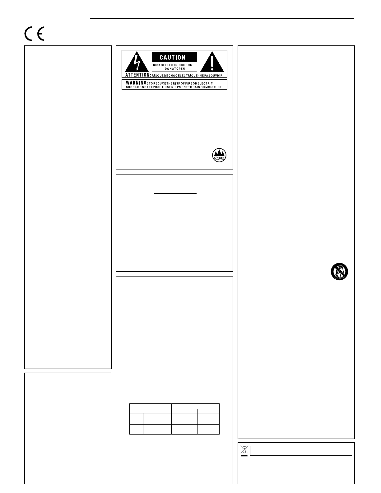
The symbols shown above are internationally accepted symbols that warn of potential hazards
with electrical products. The lightning flash with arrowpoint in an equilateral triangle means that
there are dangerous voltages present within the unit. The exclamation point in an equilateral
triangle indicates that it is necessary for the user to refer to the owner’s manual.
These symbols warn that there are no user serviceable parts inside the unit. Do not open the unit.
Do not attempt to service the unit yourself. Refer all servicing to qualified personnel. Opening the
chassis for any reason will void the manufacturer’s warranty. Do not get the unit wet. If liquid is
spilled on the unit, shut it off immediately and take it to a dealer for service. Disconnect the unit
during storms to prevent damage.
The following is indicative of low altitude use; do not use this product
above 2000m.
ELECTROMAGNETIC
COMPATIBILITY
This device complies with part 15 of the FCC Rules and
the Product Specifications noted on the Declaration of
Conformity. Operation is subject to the following two
conditions:
•
this device may not cause harmful interference, and
•
this device must accept any interference received,
including interference that may cause undesired
operation.
Operation of this unit within significant
electromagnetic fields should be avoided.
•
use only shielded interconnecting cables.
SAFETY INSTRUCTIONS
NOTICE FOR CUSTOMERS IF YOUR UNIT IS EQUIPPED WITH A POWER CORD.
WARNING: THIS APPLIANCE SHALL BE CONNECTED TO A MAINS SOCKET OUTLET WITH A
PROTECTIVE EARTHING CONNECTION.
The cores in the mains lead are coloured in accordance with the following code:
GREEN and YELLOW - Earth BLUE - Neutral BROWN - Live
As colours of the cores in the mains lead of this appliance may not correspond with the
coloured markings identifying the terminals in your plug, proceed as follows:
•
The core which is coloured green and yellow must be connected to the terminal in the plug
marked with the letter E, or with the earth symbol, or coloured green, or green and yellow.
•
The core which is coloured blue must be connected to the terminal marked N or
coloured black.
•
The core which is coloured brown must be connected to the terminal marked L or
coloured red.
This equipment may require the use of a different line cord, attachment plug, or both,
depending on the available power source at installation. If the attachment plug needs to be
changed, refer servicing to qualified service personnel who should refer to the table below.
The green/yellow wire shall be connected directly to the units chassis.
CONDUCTOR
L LIVE BROWN BLACK
N NEUTRAL BLUE WHITE
E EARTH GND
WARNING: If the ground is defeated, certain fault conditions in the unit or in the system to
which it is connected can result in full line voltage between chassis and earth ground. Severe
injury or death can then result if the chassis and earth ground are touched simultaneously.
WARNING:
WIRE COLOR
Normal Alt
GREEN/
YEL
GREEN
• Apparatet må tilkoples jordet stikkontakt.
• Apparaten skall anslutas till jordat uttag.
• Laite on liitettävä suojakoskettimilla varustettuun pistorasiaan.
WARNING FOR YOUR PROTECTION
READ THE FOLLOWING:
KEEP THESE INSTRUCTIONS
HEED ALL WARNINGS
FOLLOW ALL INSTRUCTIONS
THE APPARATUS SHALL NOT BE EXPOSED TO DRIPPING OR SPLASHING LIQUID
AND NO OBJECT FILLED WITH LIQUID, SUCH AS VASES, SHALL BE PLACED ON
THE APPARATUS
CLEAN ONLY WITH A DRY CLOTH.
FOR INDOOR USE ONLY.
DO NOT BLOCK ANY OF THE VENTILATION OPENINGS. INSTALL IN ACCORDANCE
WITH THE MANUFACTURER’S INSTRUCTIONS.
DO NOT INSTALL NEAR ANY HEAT SOURCES SUCH AS RADIATORS, HEAT REGISTERS,
STOVES, OR OTHER APPARATUS (INCLUDING AMPLIFIERS) THAT PRODUCE HEAT.
ONLY USE ATTACHMENTS/ACCESSORIES SPECIFIED BY THE MANUFACTURER.
UNPLUG THIS APPARATUS DURING LIGHTNING STORMS OR WHEN UNUSED FOR
LONG PERIODS OF TIME.
Do not defeat the safety purpose of the polarized or grounding-type plug. A polarized
plug has two blades with one wider than the other. A grounding type plug has two
blades and a third grounding prong. The wide blade or third prong are provided for
your safety. If the provided plug does not fit your outlet, consult an electrician for
replacement of the obsolete outlet.
Protect the power cord from being walked on or pinched particularly at plugs, convenience receptacles, and the point where they exit from the apparatus.
Use only with the cart stand, tripod bracket, or table specified
by the manufacture, or sold with the apparatus. When a cart is
used, use caution when moving the cart/apparatus combination
to avoid injury from tip-over.
Refer all servicing to qualified service personnel. Servicing is required when the apparatus has been damaged in any way, such as power-supply cord or plug is damaged,
liquid has been spilled or objects have fallen into the apparatus, the apparatus has
been exposed to rain or moisture, does not operate normally, or has been dropped.
POWER ON/OFF SWITCH: For products provided with a power switch, the power
switch DOES NOT break the connection from the mains.
MAINS DISCONNECT: The plug shall remain readily operable. For rack-mount or
installation where plug is not accessible, an all-pole mains switch with a contact
separation of at least 3 mm in each pole shall be incorporated into the electrical
installation of the rack or building.
FOR UNITS EQUIPPED WITH EXTERNALLY ACCESSIBLE FUSE RECEPTACLE: Replace
fuse with same type and rating only.
MULTIPLE-INPUT VOLTAGE: This equipment may require the use of a different line
cord, attachment plug, or both, depending on the available power source at installation.
Connect this equipment only to the power source indicated on the equipment rear
panel. To reduce the risk of fire or electric shock, refer servicing to qualified service
personnel or equivalent.
If connected to a 240V supply, a suitable CSA/UL certified power cord shall be
used for this supply.
POWER ADAPTER: Ensure a minimum of 8 inches of clearance and ventilation
around the adapter.
If you want to dispose this product, do not mix it with general household waste. There is a
separate collection system for used el ectronic products in accordance w ith legislation that
requires proper treatment, recovery and recycling.
Private household in the 25 member states of the EU, in Switzerland and Norway may return their used
electronic products free of charge to designated collection facilities or to a retailer (if you purchase a similar
new one).
For Countries not mentioned above, please contact your local authorities for a correct method of disposal.
By doing so you will ensure that your disposed product undergoes the necessary treatment, recovery and
recycling and thus prevent potential negative effects on the environment and human health.
Page 3
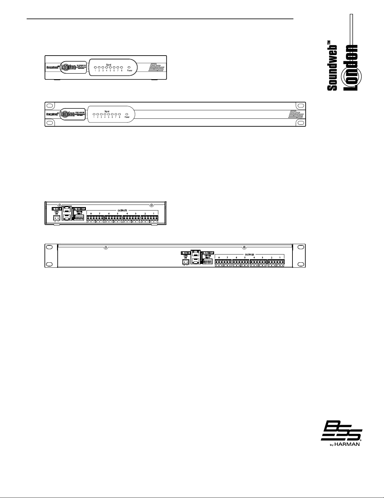
Front panel
BLU-BOB1
BLU-BOB2
Signal
The Signal LED illuminates for each channel where a signal is present.
Power
The Power LED illuminates when the BLU-BOB device is powered on.
Rear panel
BLU-BOB1
BLU-BOB2
12VDC Power Adapter
The BLU-BOB Break-Out Box output expanders are powered by a 12V DC adapter that is
included with the device (part number: PS1225DC-S/T). Use only the adapter provided.
BLU link In/Out
The Soundweb London Digital Audio Bus is a high bandwidth, fault-tolerant bus of 256
channels at 48kHz and 128 channels at 96kHz. Devices are connected, using Cat 5e or
Cat 6 cable, in a ring from the OUT connector of one device to the IN connector of the
adjacent device. The distance between devices in the ring can be up to 100m on Cat 5e
or Cat 6 or up to 10km on single mode ber using the MC-1 ber media converter. The
ring topology allows any single cable fault without loss of channels. All devices within a
given Digital Audio Bus ring must be congured for the same sample rate. The sample rate
of the BLU-BOB1 and BLU-BOB2 devices is automatically congured based on remotely
congured devices within the Digital Audio Bus ring.
PLEASE NOTE: BLU-BOBs with version numbers below v1.05 are not compatible with
“pull-down” sample rates (i.e., running 47.952kHz for system clock instead of 48kHz;
or running 95.904kHz for system clock instead of 96kHz). Pull-down sample rates are
occasionally required in video post-production environments in the United States. If the
design requires pull-down and you have a pre v1.05 BLU-BOB, please contact Customer
Services at [email protected] for guidance. BLU-BOBs with a sticker on the rear
panel showing V1.05 or above are compatible with pull-down rates.
1
Page 4
Channel Select
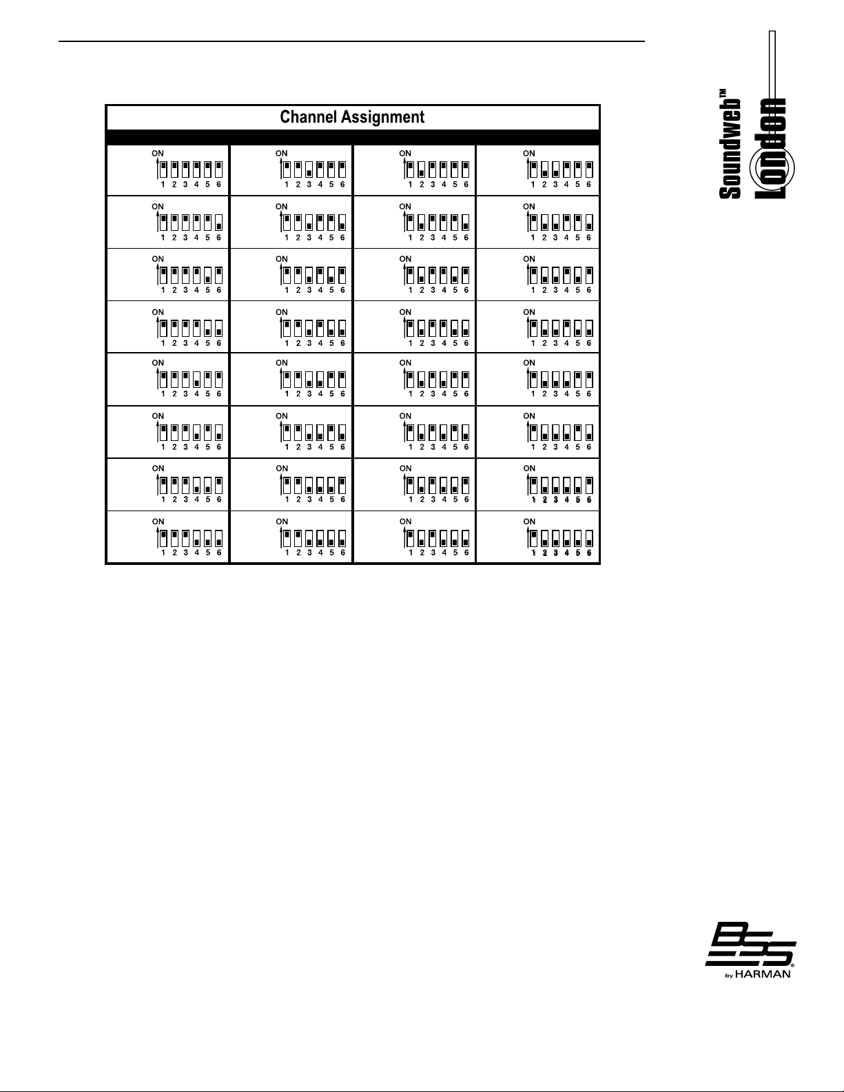
The BLU-BOB output channels are easily congured by six DIP switches located on the
rear of the device, which select a range of 8 consecutive channels from the Digital Audio
Bus. Output channel assignments are congured by DIP switch selection only. The BLUBOB is not congured by HiQnet™ London Architect.
Analog Output 1-8
The 8 analog line level outputs utilize the same terminal block connectors (part number:
32-1226) as all other members of the Soundweb London family (except for BLU-100,
BLU-101, and BLU-102, which require smaller connectors).
Installing BLU-BOB into a Rack
The BLU-BOB2 and the BLU-BOB1 each offer 8 channels of line-level analog output
expansion from the Soundweb London digital audio bus (informally known as “BLU
link”). The BLU-BOB2 can be mounted directly into a single 1U rack space. The BLU-
BOB1 is a half-width version, and it requires the Rack-Mount Kit to mount it into a single
1U rack space (see “Using the Rack-Mount Kit” section for more info).
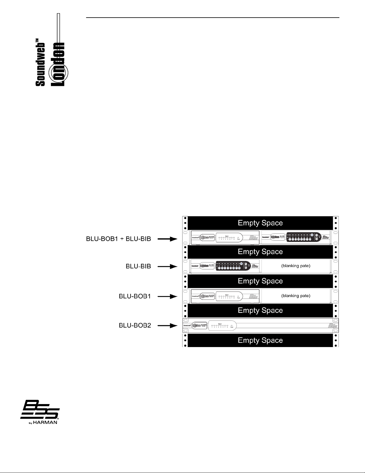
When installing a BLU-BOB2 or any combination of BLU-BOB1s and/or BLU-BIBs into
a single rack space, it is recommended that one empty rack space is left above and
below the devices. This allows heat to safely dissipate. See the below diagram for further
clarication.
Using the Rack-Mount Kit (shipped separately)
The BSS Audio 1U Rack-Mount Kit (SKU: RACK MOUNT KIT) allows up to two half-
rack Soundweb London devices—BLU-BIB and BLU-BOB1—to be mounted on a shelf
occupying a single rack space. The 1U Rack-Mount Kit can accommodate one BLU-BIB
device, one BLU-BOB1 device, two BLU-BIB devices, two BLU-BOB1 devices, or one of
each device. With each device offering eight channels of analog I/O expansion, the 1U
Rack-Mount Kit allows for higher I/O density (16 channels) in a single rack space.
For instances in which only one I/O expander is mounted, the half-rack blanking plate
(included with the RACK MOUNT KIT) can be used to ll the blank space in the front of
the rack.
2
Page 5
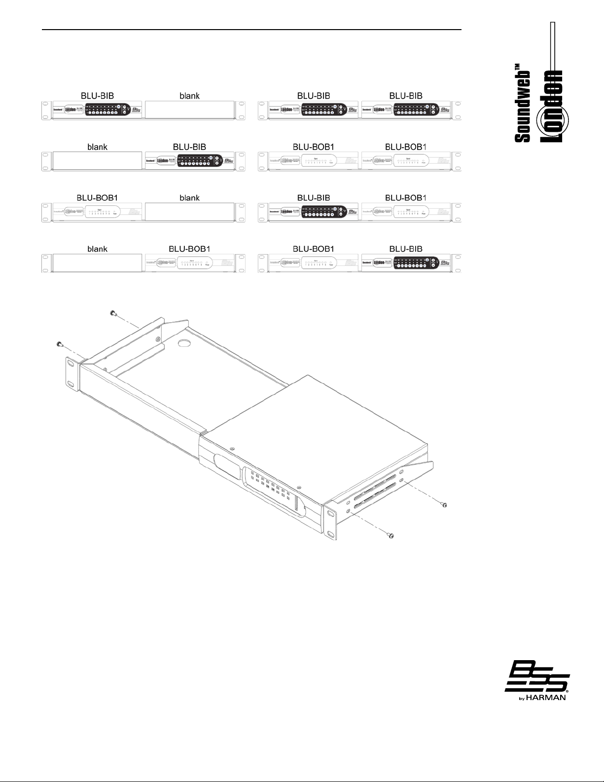
Possible BLU-BIB / BLU-BOB1 Rack-Mount Positions
Securing a Device and Blanking Plate to the Shelf
3
Page 6
TECHNICAL SPECIFICATIONS:
Front Panel LED Indicators:
Analog Outputs: 8 electronically balanced on Phoenix/Combicon
removable screw connectors
Maximum Output Level: +19dBu
Frequency Response: 20Hz-20KHz (+0.5dB/-1dB)
THD: <0.01% 20Hz to 20KHz, +10dBu output
Dynamic Range: 110dB typical, 20Hz-20KHz unweighted
Crosstalk: <-105dB 20Hz-20KHz
D/A Latency: 28/Fs (0.58ms@48k, 0.29ms@96k)
Output Impedence: 40 Ω balanced / 20 Ω unbalanced
Digital Audio Bus:
Connectors: 2 x RJ45 Ethernet connectors
Maximum Cable Length: 100m/300ft on Category 5e cable between devices
Maximum Number of Nodes: 60
Latency Per Node: 4/Fs (0.08ms@48k, 0.04ms@96k)
Power and Dimensions:
Power Supply: 12VDC external adapter (included)
AC Power Input to Adapter: 19W
BTU Rating: 65 BTU/hr
Operating Temperature Range: 5 (41) to 35 (95) degrees C (degrees F)
Dimensions BLU-BOB1 (H(U) x W x D): 1.65” (1U) x 8.63” x 7.75” (42mm x 219mm x 197mm)
Dimensions BLU-BOB2 (H(U) x W x D): 1.75” (1U) x 19” x 7.75” (45mm x 483mm x 197mm)
Weight BLU-BOB1: 2.96 lbs / 1.34 kg
Weight BLU-BOB2: 5.13 lbs / 2.33 kg
Signal present per output, and Power
4
Page 7
Note #6
far side
CHANNELS DIP SWITCH SETTINGS CHANNELS DIP SWITCH SETTINGS CHANNELS DIP SWITCH SETTINGS CHANNELS DIP SWITCH SETTINGS
1 to 8
9 to 16
17 to 24
25 to 32
33 to 40
41 to 48
49 to 56
57 to 64
65 to 72
73 to 80
81 to 88
89 to 96
97 to 104
105 to 112
113 to 120
121 to 128
129 to 136
137 to 144
145 to 152
153 to 160
161 to 168
169 to 176
177 to 184
185 to 192
193 to 200
201 to 208
209 to 216
217 to 224
225 to 232
233 to 240
241 to 248
249 to 256
Note: Lowest channel of 8 channel range is always output 1 of BLU-BOB
5
Page 8

BSS Audio
8760 South Sandy Parkway
Sandy, Utah 84070
801-566-8800
www.bssaudio.com
Printed in the USA
 Loading...