

Page 1

SoundwebTM London
BLU-800/BLU-320/BLU-160/
BLU-120
Installation Guide
18-0553-A
1
Page 2
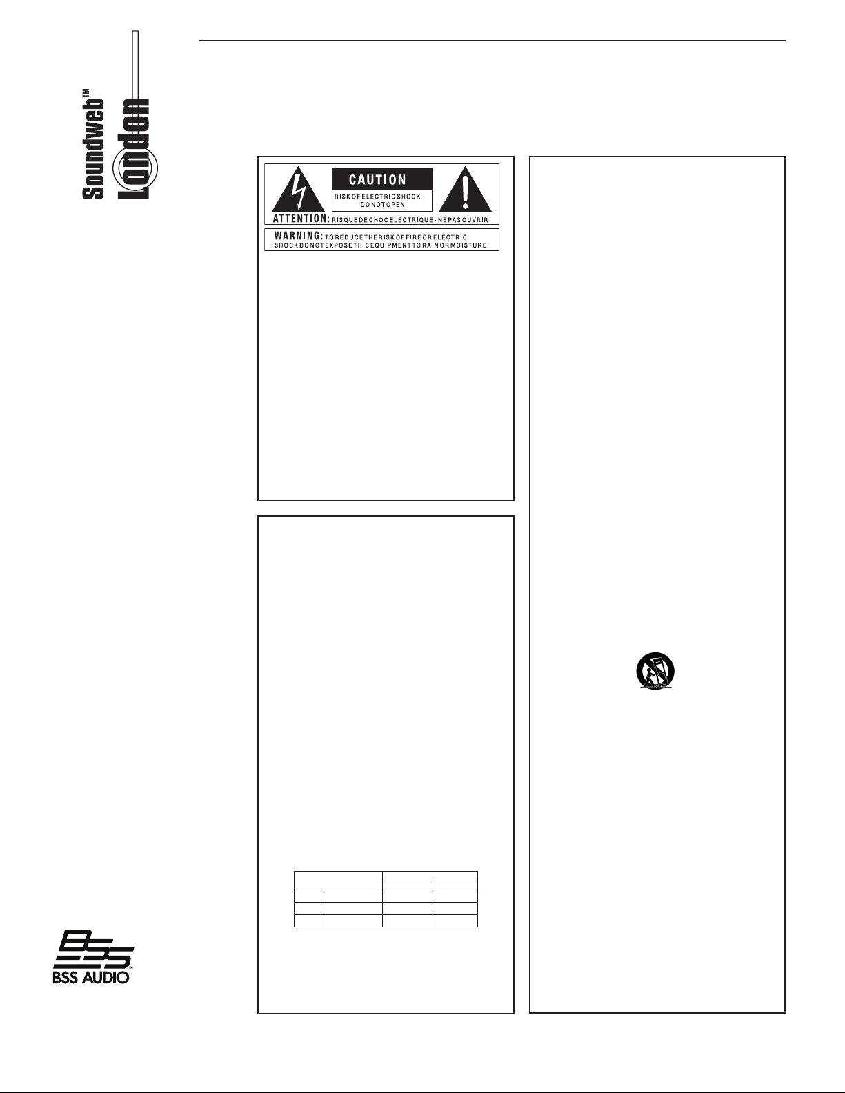
IMPORTANT SAFETY INSTRUCTIONS
The symbols shown above are internationally accepted symbols
that warn of potential hazards with electrical products. The
lightning flash with arrowpoint in an equilateral triangle means
that there are dangerous voltages present within the unit. The
exclamation point in an equilateral triangle indicates that it is
necessary for the user to refer to the owner’s manual.
These symbols warn that there are no user serviceable parts inside
the unit. Do not open the unit. Do not attempt to service the
unit yourself. Refer all servicing to qualified personnel. Opening
the chassis for any reason will void the manufacturer’s warranty.
Do not get the unit wet. If liquid is spilled on the unit, shut it off
immediately and take it to a dealer for service. Disconnect the
unit during storms to prevent damage.
SAFETY INSTRUCTIONS
NOTICE FOR CUSTOMERS IF YOUR UNIT IS EQUIPPED WITH A POWER CORD.
WARNING: THIS APPLIANCE SHALL BE CONNECTED TO A MAINS SOCKET OUTLET
WITH A PROTECTIVE EARTHING CONNECTION.
The cores in the mains lead are coloured in accordance with the following code:
GREEN and YELLOW - Earth BLUE - Neutral BROWN - Live
As colours of the cores in the mains lead of this appliance may not correspond
with the coloured markings identifying the terminals in your plug, proceed
as follows:
•
The core which is coloured green and yellow must be connected to
the terminal in the plug marked with the letter E, or with the earth
symbol, or coloured green, or green and yellow.
•
The core which is coloured blue must be connected to the terminal
marked N or coloured black.
•
The core which is coloured brown must be connected to the terminal
marked L or coloured red.
This equipment may require the use of a different line cord, attachment
plug, or both, depending on the available power source at installation.
If the attachment plug needs to be changed, refer servicing to qualified
service personnel who should refer to the table below. The green/yellow wire shall be connected directly to the units chassis.
CONDUCTOR
L LIVE BROWN BLACK
N NEUTRAL BLUE WHITE
E EARTH GND GREEN/YEL GREEN
WARNING: If the ground is defeated, certain fault conditions in the unit
or in the system to which it is connected can result in full line voltage
between chassis and earth ground. Severe injury or death can then
result if the chassis and earth ground are touched simultaneously.
WIRE COLOR
Normal Alt
WARNING FOR YOUR PROTECTION
PLEASE READ THE FOLLOWING:
KEEP THESE INSTRUCTIONS
HEED ALL WARNINGS
FOLLOW ALL INSTRUCTIONS
THE APPARATUS SHALL NOT BE EXPOSED TO DRIPPING OR SPLASHING
LIQUID AND NO OBJECT FILLED WITH LIQUID, SUCH AS VASES, SHALL
BE PLACED ON THE APPARATUS
CLEAN ONLY WITH A DRY CLOTH.
DO NOT BLOCK ANY OF THE VENTILATION OPENINGS. INSTALL IN
ACCORDANCE WITH THE MANUFACTURER’S INSTRUCTIONS.
DO NOT INSTALL NEAR ANY HEAT SOURCES SUCH AS RADIATORS, HEAT
REGISTERS, STOVES, OR OTHER APPARATUS (INCLUDING AMPLIFIERS)
THAT PRODUCE HEAT.
ONLY USE ATTACHMENTS/ACCESSORIES SPECIFIED BY THE MANU
FACTURER.
UNPLUG THIS APPARATUS DURING LIGHTNING STORMS OR WHEN
UNUSED FOR LONG PERIODS OF TIME.
Do not defeat the safety purpose of the polarized or grounding-type plug.
A polarized plug has two blades with one wider than the other. A grounding
type plug has two blades and a third grounding prong. The wide blade or
third prong are provided for your safety. If the provided plug does not fit your
outlet, consult an electrician for replacement of the obsolete outlet.
Protect the power cord from being walked on or pinched particularly at
plugs, convenience receptacles, and the point where they exit from the
apparatus.
Use only with the cart stand, tripod bracket, or table specified by the
manufacture, or sold with the apparatus. When a cart is used, use caution
when moving the cart/apparatus combination to avoid injury from tip-over.
Refer all servicing to to qualified service personnel. Servicing is required
when the apparatus has been damaged in any way, such as power-supply
cord or plug is damaged, liquid has been spilled or objects have fallen into
the apparatus, the apparatus has been exposed to rain or moisture, does
not operate normally, or has been dropped.
POWER ON/OFF SWITCH: For products provided with a power switch, the
power switch DOES NOT break the connection from the mains.
MAINS DISCONNECT: The plug shall remain readily operable. For rackmount or installation where plug is not accessible, an all-pole mains switch
with a contact separation of at least 3 mm in each pole shall be incorporated
into the electrical installation of the rack or building.
FOR UNITS EQUIPPED WITH EXTERNALLY ACCESSIBLE FUSE RECEPTACLE:
Replace fuse with same type and rating only.
MULTIPLE-INPUT VOLTAGE:
ent line cord, attachment plug, or both, depending on the available power
source at installation. Connect this equipment only to the power source
indicated on the equipment rear panel. To reduce the risk of fire or electric
shock, refer servicing to qualified service personnel or equivalent.
This equipment may require the use of a differ-
-
2
Page 3
IMPORTANT SAFETY INSTRUCTIONS
If you want t o dispose this product, do not mix it with general house hold waste . There i s a
separate collection system for used electronic products i n acco rdance with leg islation that
requires proper treat ment, recovery and recycling.
Private household in the 25 member states of the EU, in Switzerland and Norway may return their used
electronic products free of charge to designated collection facilities or to a retailer (if you purchase a similar
new one).
For Countries not mentioned above, please contact your local authorities for a correct method of disposal.
By doing so you will ensure that your disposed product undergoes the necessary treatment, recovery and
recycling and thus prevent potential negative effects on the environment and human health.
DECLARATION OF CONFORMITY
Manufacturer’s Name: BSS Audio
Manufacturer’s Address: 8760 S. Sandy Parkway
Sandy, Utah 84070, USA
declares that the product:
Product name: BLU 120, BLU 160, BLU 320, BLU 800
Note: Product name may be suffixed by the letters-EU.
Product option: Various combinations of Input / Output Cards
conforms to the following Product Specifications:
Safety: EN 60065 (7th ed. 2001)
EMC: EN 55103 (2001+A1)
EN 55103 (1998)
Supplementary Information:
The product herewith complies with the requirements of the Low Voltage
Directive 73/23/EEC and the EMC Directive 89/336/EEC as amended by
Directive 93/68/EEC.
Director of Engineering – BSS Audio
8760 S. Sandy Parkway
Sandy, Utah 84070, USA
Date: February 1, 2008
European Contact: Your local BSS Audio Sales and Service Office or
Harman Music Group
8760 South Sandy Parkway
Sandy, Utah 84070, USA
Ph: (801) 566-8800
Fax: (801) 566-7005
U.K. MAINS PLUG WARNING
A molded mains plug that has been cut off from the cord is unsafe. Discard
the mains plug at a suitable disposal facility. NEVER UNDER ANY
CIRCUMSTANCES SHOULD YOU INSERT A DAMAGED OR CUT
MAINS PLUG INTO A 13 AMP POWER SOCKET. Do not use the
mains plug without the fuse cover in place. Replacement fuse covers can be
obtained from your local retailer. Replacement fuses are 13 amps and MUST
be ASTA approved to BS1362.
ELECTROMAGNETIC
COMPATIBILITY
This unit conforms to the Product Specifications noted
on the Declaration of Conformity. Operation
is subject
to the following two conditions:
•
this device may not cause harmful
interference, and
•
this device must accept any interference received,
including interference that may cause undesired
operation.
Operation of this unit within significant
electromagnetic fields should be avoided.
•
use only shielded interconnecting cables.
3
Page 4
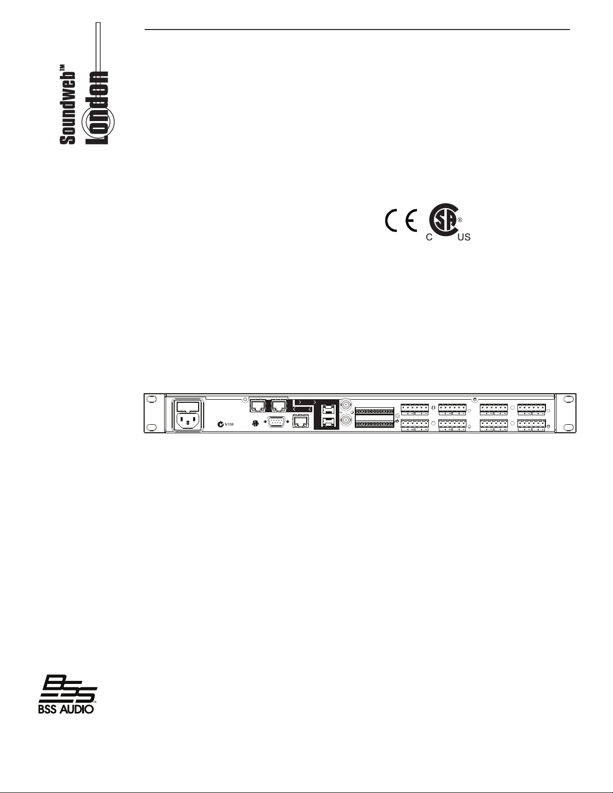
Regulatory information
OF FIRE REPLACE ONLY WITH THE
ETHERNET
PRIMARY
SECONDARY
A
12341
23
4
B
C
D
IN
OUT
CAUTION:
TO REDUCE THE RISK
SAME TYPE AND RATING OF FUSE
AVIS:
UTILISER UN FUSIBLE DE
RECHANGE DE MEME TYPE
THIS EQUIPMENT MUST BE EARTHED
MANUFACTURED IN
THE USA BY
BSS AUDIO
RS232LOCATE
SSSS
SSSS
SSSS
SSSS
BUDDYLINK / 48K
T1.6 AH - 2 50 V F USE
100-240V ~ 50/60Hz, 55W
CobraNet
BLU link
IN
OUT
An example of this equipment has been tested and found to comply with the following European
and international Standards for Electromagnetic Compatibility and Electrical Safety:
Radiated Emissions (EU): EN55013 (2001+A1)
Immunity (EU): EN55020 (1998)
Electrical Safety (EU): IEC60065-01 + AMD1
Electrical safety (USA): UL60065-06
Important user information
Do not remove covers. No user serviceable parts inside, refer servicing to qualied service
personnel. For continued compliance with international EMC regulations, it is important that all
cables be screened, and connected as follows: Audio cable screens to their BLU-800 connector
ground. Control cable screens to the ground screws adjacent to the connector. Network cables
should be of type CAT.5, tted with a clip-on ferrite sleeve (STEWART TYPE 28A2029-0A0) near
the network socket end. This equipment must be earthed. It should not be necessary to remove
any protective earth or signal cable shield connections to prevent ground loops. Any such
disconnections are outside the recommended practice of BSS Audio, and will render the EMC or
safety certicate void.
Mechanical installation
If the unit is likely to undergo extreme vibration through extensive road trucking and touring, the
unit must be supported at the rear and/or sides to lessen the stress on the front mounting ange.
Rear rack supports are provided to reduce stress on front mounting ange. Damage caused by
insufcient support is not covered by the warranty. To prevent cosmetic damage to the front panel
nish, use protective plastic cups under the rack mounting bolts.
4
Page 5
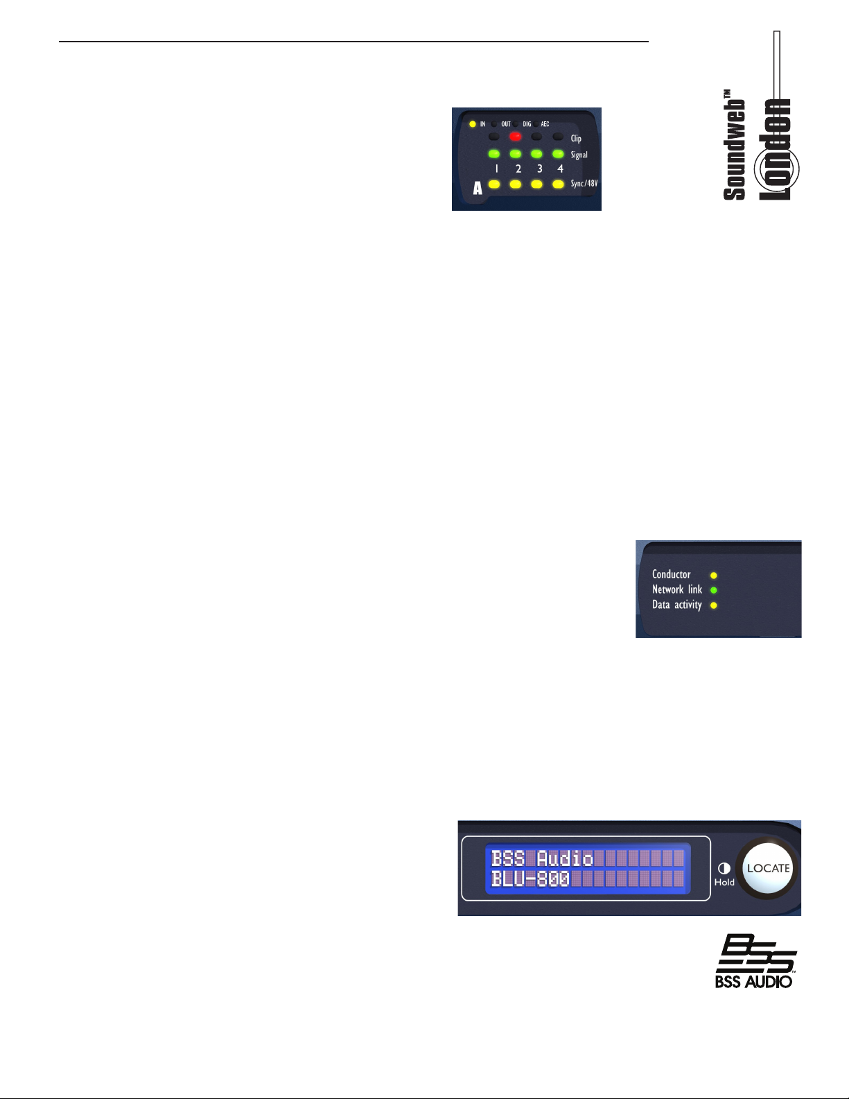
Front panel
Input card monitoring
Each channel has 3 LED indicators showing:
Clip
Illuminated - Indicates clipping in the analogue
domain for each channel of the tted Input or Output card. The LED will illuminate at
+18.5dB.
Signal
Illuminated - The Signal LED will illuminate for each channel of a tted Input or Output
card when the signal reaches or exceeds the signal threshold of -20dB.
Phantom
Illuminated - Illuminates to indicate +48V phantom power has been activated for the
relevant channel of a tted input card.
Conductor
The master clock device of a CobraNetTM system is referred to as the Conductor - the CM1 modules in the system auto-negotiate which device will transmit the Conductor beat
packet. The LED illuminates to indicate which device is acting as the Conductor.
Network Link
The Network Link indicates the presence of Cat 5 Ethernet cables. If no
cables are connected, the LED is unlit; the LED ashes is either a control
or CobraNetTM cable is tted and remains illuminated if both cables are
connected.
Data Activity
The Data Activity LED will ash to indicate that the device is communicating
with another control device, either on the network or via the serial or control ports.
LCD Display
Top line Indicates device name and run state.
Bottom line indicates Time, IP Address, Subnet Mask, Model number with rmware
version.
LOCATE
Pressing the Locate switch on the front of the
unit will illuminate the Locate switch on the rear
and identify the device within London Architect.
Similarly the switch will illuminate if the device is
selected from within London Architect or from the
Locate switch on the rear.
Contrast (Hold)
Pressing and holding the Locate switch will cycle the LCD through its contrast range.
5
Page 6
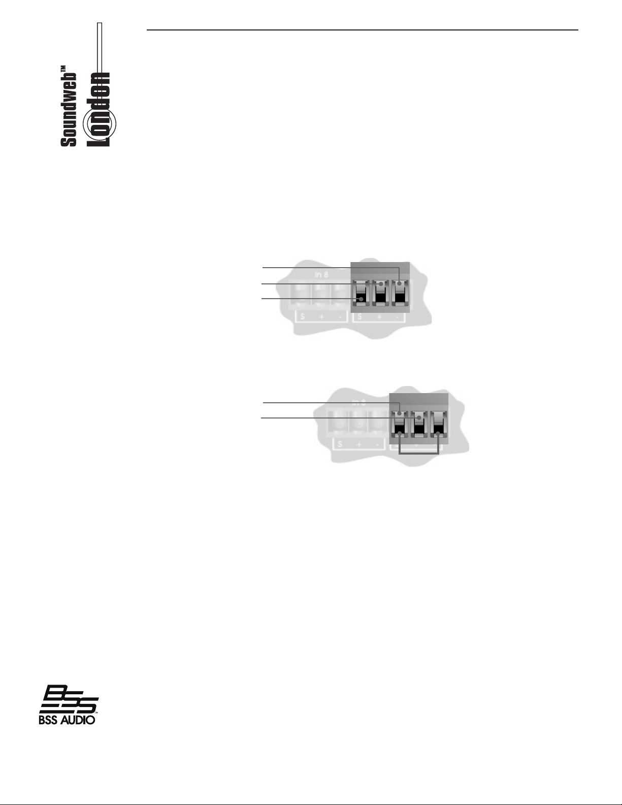
Audio cable wiring
All audio and control connections to the BLU-800/BLU-320/BLU-160/BLU-120 are via
Klippon pluggable terminal block connectors (also known as BL, Phoenix or Combicon).
6-way female Klippon connectors are supplied for making these connections.
Audio Input and Output wiring convention
Soundweb products provide cable shielding ‘back from the destination’ to eliminate
ground loop problems. This means that the shield (S) connection on an input is
grounded, whereas the shield connection on an output is oating (although connected
via an internal network to ground for EMC compliance).
Balanced wiring - The convention for balanced wiring (2-core plus shield) is:
Balanced connection BLU-800 connection
Pin 3: Cold ‘-’
Pin 2 : Hot ‘+’
Pin 1 : Shield
Unbalanced wiring - The convention for unbalanced wiring to the inputs (1-core plus
shield) is:
Unbalanced connection BLU-800 connection
Pin 1: Shield
Pin 2 : Hot ‘+’
Pin 3 : Link to Pin 1
(Optional for BLU-800 inputs)
6
Page 7
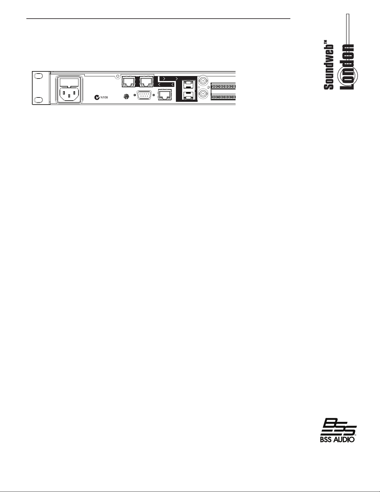
Rear panel
OF FIRE REPLACE ONLY WITH THE
ETHERNET
PRIMARY
SECONDARY
A
12341
23
4
B
C
D
IN
OUT
CAUTION:
TO REDUCE THE RISK
SAME TYPE AND RATING OF FUSE
AVIS:
UTILISER UN FUSIBLE DE
RECHANGE DE MEME TYPE
THIS EQUIPMENT MUST BE EARTHED
MANUFACTURED IN
THE USA BY
BSS AUDIO
RS232LOCATE
SSSS
SSSS
SSSS
SSSS
BUDDYLINK / 48K
T1. 6AH - 250 V FUS E
100-240V ~ 50/60Hz, 55W
CobraNet
BLU link
IN
OUT
BLU-800 shown. BLU-320 layout is identical.
BLU-160 and BLU-120 have no CobraNetTM or Buddy Link connections but is otherwise
identical to the BLU-800 and BLU-320.
AC Mains
AC Mains input to the universal switched-mode power supply, operates over a wide range
of AC input voltages from 100V to 240V, 50/60Hz.
CobraNet Connectors - Primary/Secondary
The CobraNetTM compatible devices within the SoundwebTM London system are tted
with a Peak Audio Cobranet
a Secondary CobranetTM port. Under normal operation the Primary port only receives
audio data from and transmits audio data to the network. Should the Primary port or
connection fail, the CM-1 module automatically switches to receive from and transmit
with the Secondary port.
Locate
Pressing the Locate switch on the rear of the unit will illuminate the Locate switch on the
front and identify the device within London Architect. Similarly the switch will illuminate
if the device is selected from within London Architect or from the Locate switch on the
front panel.
RS232
Serial port for connection of external control equipment.
TM
CM-1 module. The module itself offers a Primary and
Ethernet
The main connection for the proprietary system control network, and for third party
Ethernet control.
BLU link
The London BLU link is a point-to-point digital audio bus with 256 audio channels at
48K sample rate or 128 audio channels at 96K sample rate. The physical connection is
made with cat5e cable from the OUT port of one device to the IN port of another device.
The devices are connected in a daisy chain fashion continuing with the OUT port of one
device connected to the IN port of the next device. Redundancy can be provided by
completing the loop and connecting the OUT port from the last device to the IN port of
the rst device in the chain. All devices connected in the London BLU link chain must be
congured for the same audio sample rate.
Buddy Link/48k
The CobraNetTM Buddy Link In/Out BNC connectors allow two similarly congured
Soundweb London devices to be linked together and operate as a redundant pair with
fail-over capability. A 48kHz system clock is generated at the Buddy Link Out port.
7
Page 8
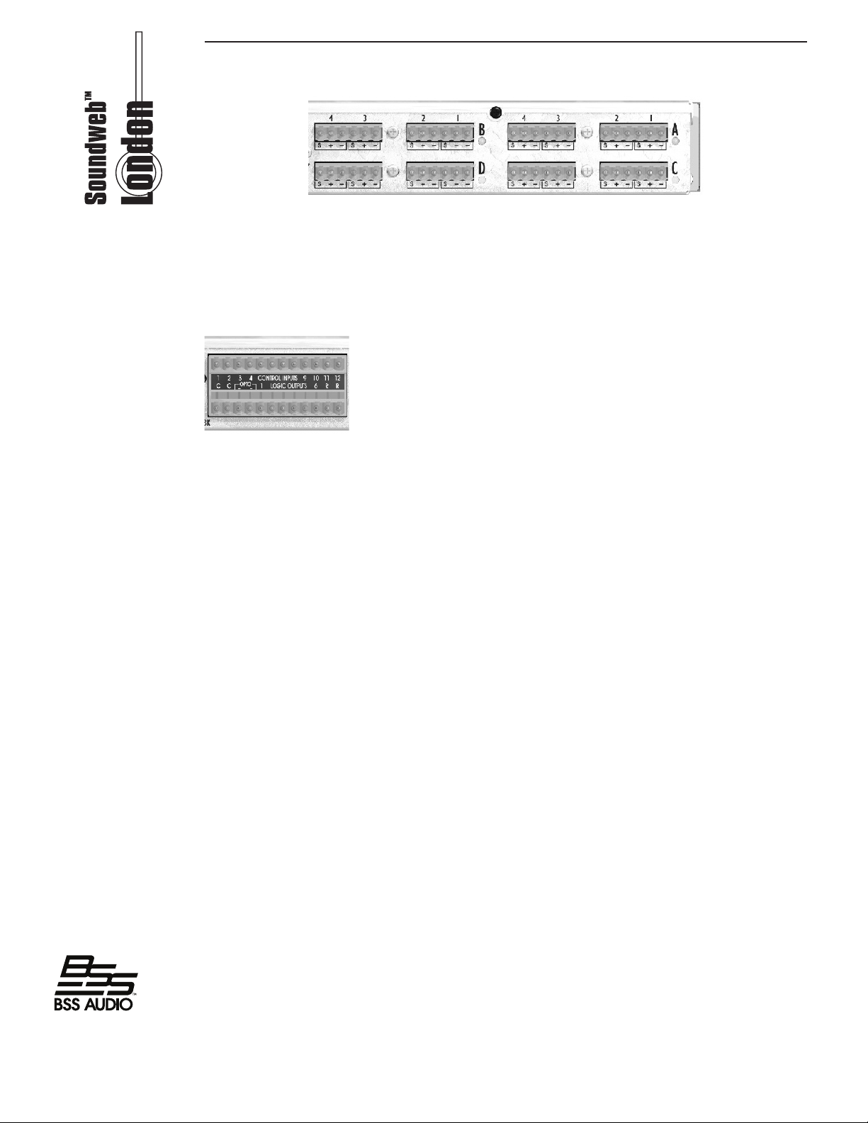
I/O Card Positions A, B, C and D
These connectors provide the balanced connections for the I/O card tted in the four card
slots in a Soundweb London device. A green LED next to the slot assignment letter A, B, C
or D indicates that an Input card is tted and an amber LED when an output card is tted.
The analogue connections are balanced, on Phoenix/Combicon connectors. Digital input
cards are indicated with a blue LED and digital outputs cards with a red LED.
CONTROL INPUTS
Used to connect switches or potentiometers, e.g. BLU-3 selector wallplate (Part no. ZBLU-3). Looking at the control port connector (on the back of the unit), there are two
common (ground) connections C to the left of the eight CONTROL INPUTS and, two
software assignable reference voltage outputs R to the right.
The control ports now have two modes of operation. In Soundweb Designer’s Control
Ports window these are labelled ‘2-wire’ and ‘3-wire’.
2-wire mode
In this mode the eight CONTROL INPUTS are internally ‘pulled up’ to +5V DC via a
4.7kOhm resistor. Therefore, no external voltage source is needed to create contact
closure to ground for switches such as mute buttons or, resistance to ground (for other
multi-state or continuous controls such as Parameter Presets or faders).
See the Soundweb Designer help for a table of resistor values for use with Parameter
Presets or source selectors.
Two ‘common’ ground connections are provided using the two C connectors to the left of
the CONTROL INPUTS.
A 47kOhm-log potentiometer (Part no. DM10018) connected between a control input
and common will allow parameters to be controlled linearly.
3-wire mode
This mode allows the use of linear pots or faders for continuous controls. A pot would be
wired as a potential divider with the top of the track connected to the reference output
R, the wiper to a control input and the bottom of the track to a common C. For good
performance pots with track resistance between 10 and 100KOhms are recommended.
LOGIC OUTPUTS
Used to connect ‘tally’ indicator LED’s or relays.
There are six standard LOGIC OUTPUTS which produce 0V or +5V DC via an internal
440 Ohm resistor and two internally connected common (ground) connections C.
An LED connected between one output (Anode, A) and common (Cathode, K) will
illuminate when the logic output is activated, without requiring any external current
limiting resistor.
A high sensitivity relay (such as a reed relay) may be driven by connecting four outputs in
parallel. This arrangement will develop 4V across a 500-Ohm coil, providing that all four
outputs are made logic 1 simultaneously.
8
Page 9
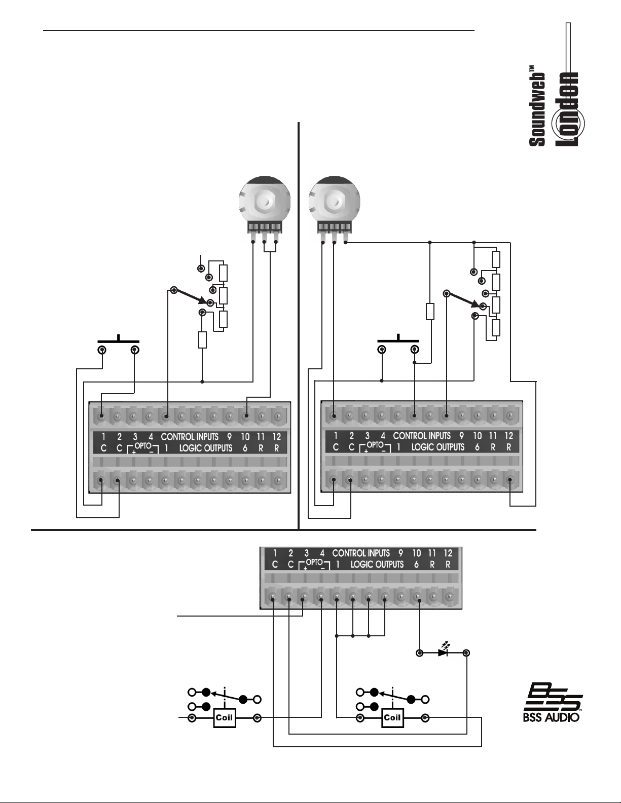
OPTO Output
In addition to the eight standard logic outputs, there is an isolated output, which fails safe (open
circuit) if the unit becomes faulty.
switch
47kOhm
log
unconnected
lad-
470R
3600R 1800R 1200R
10K-100kOhm
linear
1k
lad-
1k 1k 1k
4k7
switch
2 wire mode
+supply
ground
relay
3 wire mode
LED
relay
9
Page 10

Technical specications
FRONT PANEL LED INDICATORS Per Input: Signal Present, CLIP, SYNC/48V, I/O card type
(IN, OUT, DIG, AEC(BLU-800, 320, 160, 120))
Other: LCD Display, Conductor active, Net Link active, Data Activity
ANALOGUE INPUTS: Up to 16 electronically balanced on Phoenix/Combicon
removable screw connectors
Mic/Line Inputs: Nominal gain 0dB, electronically switchable up to +48dB,
in +6dB steps
Input impedance: 3.5kOhm
Maximum input level: +20dBu with 0dB input gain, (+8dBu with 12dB gain)
CMRR: >75dB at 1kHz
Equiv. Input Noise (EIN): <-128dBu typ. with 150 Ohms source
Phantom power: 48V nominal, selectable per input
A/D Latency: 38.7/Fs
DIGITAL INPUTS: Up to 16 AES/EBU or S/PDIF on Phoenix/Combicon
removable screw connectors
Input impedance: 110 ohm (AES/EBU), 75 ohm (S/PDIF)
Sample Rate:
Sample Rate conversion: 8kHz-96kHz
THD+N: <-140dB
Latency:
48kHz or 96kHz
3/Fso + (56.581/Fsi) + (55.658/Fso)
ANALOGUE OUTPUTS: Up to 16 electronically balanced on Phoenix/Combicon
removable screw connectors
Maximum Output Level: +19dBu
Frequency Response:
THD:
Dynamic Range: 108dB typ. (22Hz to 22kHz unweighted)
Crosstalk:
D/A Latency: 28/Fs
DIGITAL OUTPUTS: Up to 16 AES/EBU or S/PDIF on Phoenix/Combicon
removable screw connectors
Input impedance:
Sample Rate: 48kHz or 96kHz
Sample Rate conversion:
THD+N: <-140dB
Latency:
CONTROL PORTS:
Control Input Voltage:
Control Input Impedance:
Logic Output Voltage:
Logic Output Impedance:
Logic Output Current:
20Hz to 20kHz (+0.5/-1dB)
<0.01% (20Hz to 20kHz, +10dBu output)
<-75dB
110 ohm (AES/EBU), 75 ohm (S/PDIF)
8kHz-96kHz
3/Fso + (56.581/Fsi) + (55.658/Fso)
12 inputs and 6 outputs
0 to 4.5v
4.7kOhms to +5V (2-wire mode) >1MOhm (3-wire mode)
0 or +5V unloaded
440 Ohm
10mA source, 60mA sink
10
WATCHDOG OUTPUT:
Opto Output current: 14mA maximum
Phoenix/Combicon connector for failsafe control
Page 11

Withstanding voltage: 80V maximum (Off)
Series Impedance:
CONTROL NETWORK (All Models)
Connectors:
Maximum cable length:
BLU-LinkTM AUDIO NETWORK (BLU-800, 320, 160, 120)
Connectors:
Maximum cable length: 100m/300ft on Category 6 cable between devices
CobraNetTM AUDIO NETWORK (BLU-80, 32, 800, 320)
Connectors: 2 x RJ45 connectors
Maximum cable length: 100m/300ft on Category 5 cable between device and Ethernet switch
Mains Voltage: 100-240V AC, 50/60Hz
Power Consumption:
BTU Rating: <120 BTU/hr (BLU-80, 32, 16); <188 BTU/hr (BLU-800, 320, 160, 120)
Operating Temperature Range:
BSS Audio incorporates high quality mechanical fans in some products. All mechanical fans have a limited life
expectancy. We recommend annual inspection of fans for dust occlusion and excessive noise. Fan assemblies should
be replaced after six to ten years of use. Environmental factors such as elevated temperature, dust, and smoke can
adversely affect fan life. Systems exposed to these conditions should be inspected more frequently. Fan replacement can
be performed either at the factory or by an experienced technician in the eld. Please contact BSS Technical Support for
more information on purchasing replacement parts or product service.
BSS Audio has a policy of continued product improvement and accordingly reserves the right to change features and
specications without prior notice.
220 Ohms (isolated)
RJ45 Ethernet connector
100m/300ft on Category 5 cable between device and Ethernet switch
2 x RJ45 Ethernet connectors
<35VA (BLU-80, 32, 16); <55VA (BLU-800, 320, 160, 120)
5(41) to 35(95) degrees C(degrees F)
11
Page 12

BSS Audio
8760 South Sandy Parkway
Sandy, Utah 84070
801-566-8800
www.bssaudio.com
12
 Loading...