

THAT Corporation Design Note 137
Substituting THAT 2180- and 2181-Series VCAs
for THAT 2150-Series VCAs in Existing Designs
Abstract
THAT Corporation’s 2180- and 2181-series VCAs are pin-for-pin compatible, improved
performance replacements for the 2150-series VCAs. Designers may convert existing
2150-series designs to use the 2180/2181 VCAs without making any changes to existing PCB
layouts. This application note details the few component value changes and component
deletions required to obtain optimum performance with the 2180- and 2181-series VCAs in
existing 2150-series designs.
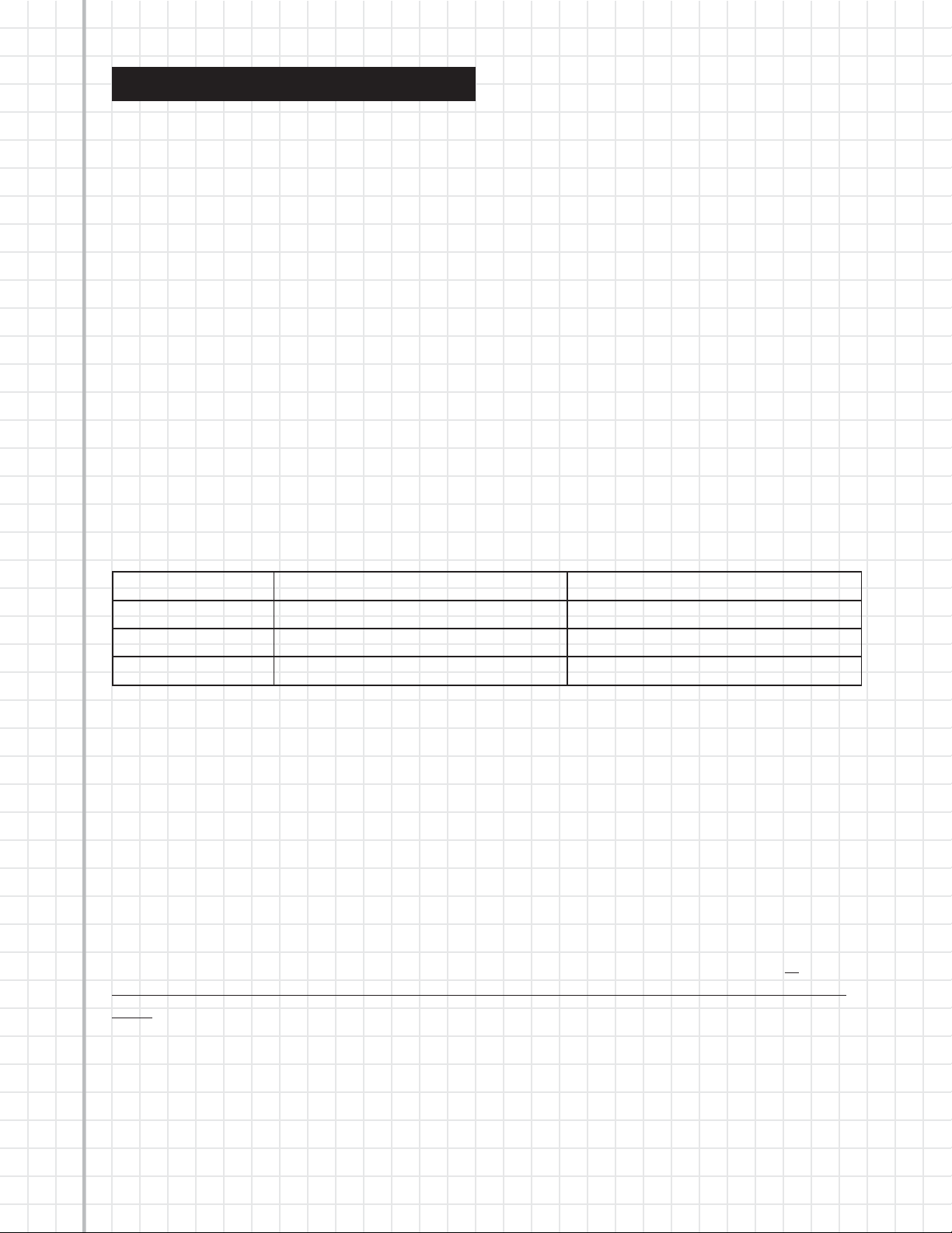
Choosing the correct VCA
Table 1 shows the correct VCA to use when switching from a THAT 2150-series part to one of
the THAT 218x-series. When retrofitting the 218x VCAs, designers may replace the
215x-series VCA with a trimmable VCA or a trimless VCA. For high performance applications,
the choice is normally to choose a trimmable 2181Lx or 2181Sx. However, where distortion
performance is less critical and trim-free production is a goal, the 2180Lx is the right choice.
1
Old VCA Precision Trimless
THAT 2155 THAT 2181LC or THAT2181SC THAT 2180LC
THAT 2150A THAT 2181LB or THAT2181SB THAT 2180LB
THAT 2151 THAT 2181LA or THAT2181SA THAT 2180LA
Table 1
2180 Series
The 2180-series VCAs are pre-trimmed at wafer stage for low THD and control-voltage
feedthrough without further adjustment. The parts are available in three grades (2180LA,
2180LB, and 2180LC) selected for factory-trimmed distortion performance, allowing the
user to optimize cost vs. performance.
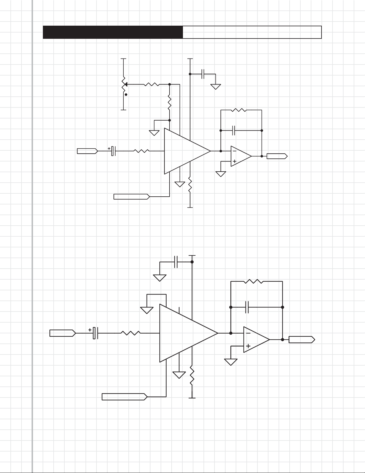
Figure 1 shows a typical 2150-series application circuit in which the negative control port
(pin 3) is used for gain control. Components R2, R3, and VR1 provide for external adjustment
of VCA symmetry. Figure 2 shows the same circuit adapted for use with a 2180-series VCA.
Note that external symmetry trim components R2, R3, and VR1 have been deleted. In
particular, R2 must not be used with the 2180 Series—it will upset the internal symmetry
trim. Capacitor C3 may be reduced in value to as low as 22 pF in order to increase the circuit
bandwidth if desired.
Figures 3 and 5 show similar 2150-series application circuits wherein the positive control
port (pins 2 and 4) or both control ports are used, respectively. Figures 4 and 6 show the
2180-series counterparts to these circuits.
Copyright © 2004 by THAT Corporation . All rights reserved. Document 600057 Rev 00
2
THAT Corporation Design Note 137
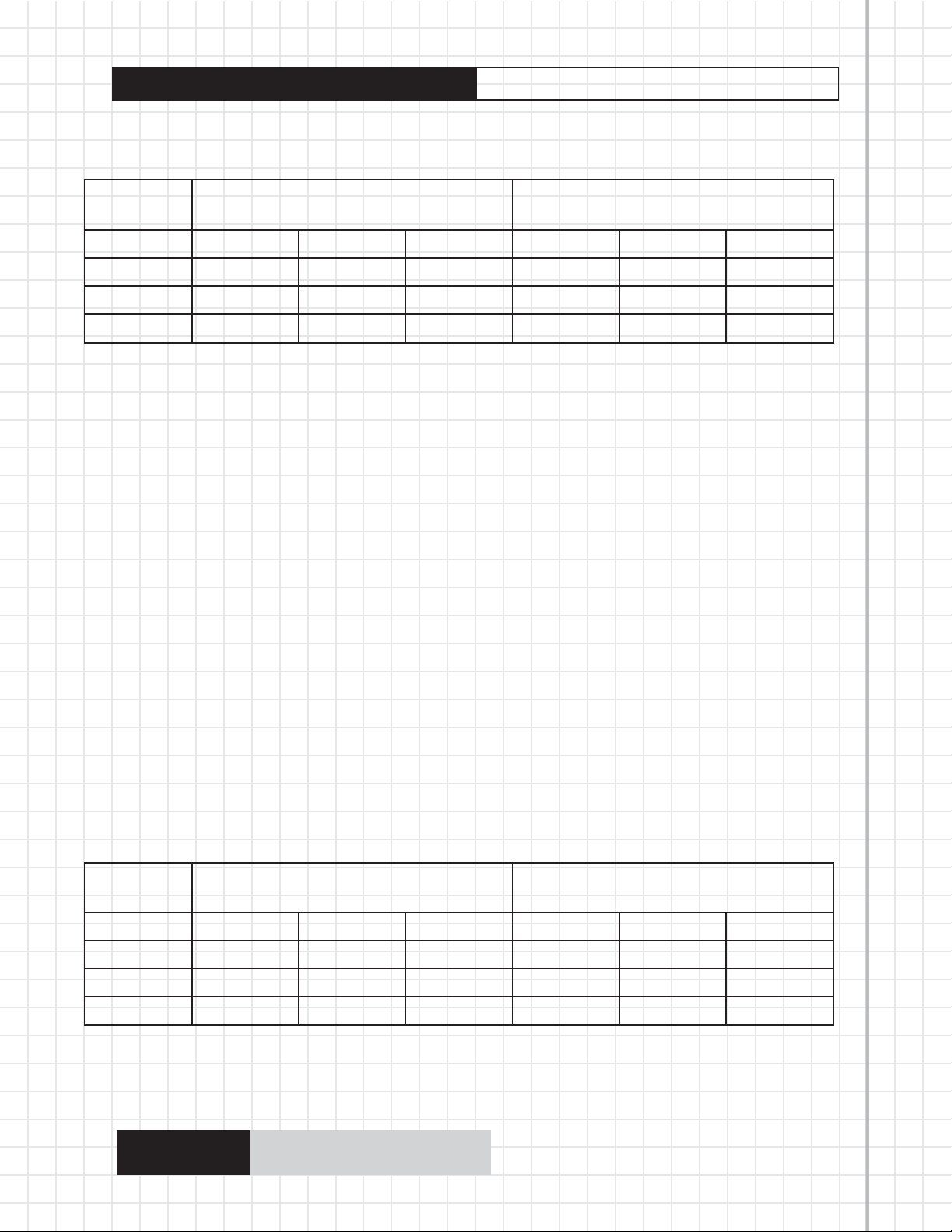
Table 2 summarizes the component deletions required to convert a typical 2150 application
to the 2180-series.
External
Component
2151 2150A 2155 2180A 2180B 2180C
R2 51 51 51 DELETE DELETE DELETE
R3 470k 390k 300k DELETE DELETE DELETE
VR1 50k 50k 50k DELETE DELETE DELETE
2150 Series 2180 Series
Table 2
Substituting the 218x for the 215x
2181 Series
The 2181-series VCAs are selected after packaging primarily on the basis of externally
trimmed THD and control-voltage feedthrough performance. The parts are selected into
three grades (2181A, 2181B, and 2181C) based on 100% tested performance after external
trim. External trimming of VCA symmetry allows higher performance than can be
consistently obtained with pretrimmed parts. Both SIP (L designation) and SO-8
(S designation) packages are available in the 2181-series. Of course, since the 2150-series
was only available in SIP, only that package applies to the retrofit situation.
Figures 7, 8, and 9 illustrate typical 2181 application circuits utilizing the negative, positive,
and both control ports respectively. Note that the external trim potentiometer VR1, and its
wiper resistor R3 are present as in the 2150 circuits, but that R2 is deleted. R2 is not
required because there is an internal 27 ohm resistor between pins 2 and 4 in all 2181-series
VCAs. The values shown for R3 are scaled differently, based on +/- 15V supplies, for each of
the three grades of these parts.
As with the 2180-series circuits, C3 may be reduced to as low as 22 pF if desired.
Table 3 summarizes the component value changes required to convert 2150-series circuits
to utilize the 2181-series VCAs (assuming V+ = +15V, V- = -15V, see the 2181 datasheet to
calculate R3 values for other supply voltages).
External
Component
2151 2150A 2155 2181A 2181B 2181C
R2 51 51 51 DELETE DELETE DELETE
R3 470k 390k 300k 680k 220k 130k
VR1 50k 50k 50k 50k 50k 50k
2150 Series 2181 Series
Table 3
THAT Corporation
45 Sumner Street, Milford MA 01757-1656
Tel: +1 (508) 478-9200 Fax: +1 (508) 478-0990
Email: info@thatcorp.com Web: www.thatcorp.com
THAT Corporation Design Note 137 Substituting the 218x for the 215x
3
2
SYM
GND
3
V+
C2
100n
R5
20k0
C3
U1
4
7
V+
V-
6
V-
OUT
5
8
R4
5k1
2
3
47p
U2A
4570
Input
V+
VR1
50k
V-
C1
47u
Control Voltage
2150A-390k
2151-470k
2155-300k
R3
R1
20k0
2150A, 2151
or 2155
R2
51R
1
EC+
IN
EC-
Figure 1. Typical 2150-series application circuit with Ec- driven
Output
1
Input
V+
C2
100n
R5
20k0
C3
2
C1
47u
2180A, 2180B
or 2180C
R1
20k0
EC+
1
IN
EC-
3
SYM
GND
6
4
U1
V+
7
8
2
47p
U2A
OUT
V-
5
3
4570
R4
5k1
Control Voltage
V-
Figure 2. Typical 2180-series application circuit with Ec- driven
1
Output
Copyright © 2004 by THAT Corporation . All rights reserved. Document 600057 Rev 00

4
THAT Corporation Design Note 137
V+
2150A-390k
2151-470k
2155-300k
R3
R1
20k0
2150A, 2151
or 2155
R2
51R
EC+
1
IN
EC-
3
Input
VR1
50k
V-
Control Voltage
C1
47u
2
Substituting the 218x for the 215x
V+
C2
100n
R5
20k0
C3
4
SYM
GND
6
U1
7
V+
OUT
V-
5
R4
5k1
8
2
3
47p
U2A
1
4570
Output
Input
V-
Figure 3. Typical 2150-series application circuit with Ec+ driven
V+
C2
100n
Control Voltage
R5
20k0
C3
2
C1
47u
2180A, 2180B
or 2180C
R1
20k0
EC+
1
IN
EC-
3
SYM
GND
6
4
7
U1
V+
OUT
V-
5
8
2
3
47p
U2A
4570
R4
5k1
1
Output
Figure 4. Typical 2180-series application circuit with Ec+ driven
THAT Corporation
V-
45 Sumner Street, Milford MA 01757-1656
Tel: +1 (508) 478-9200 Fax: +1 (508) 478-0990
Email: info@thatcorp.com Web: www.thatcorp.com

THAT Corporation Design Note 137 Substituting the 218x for the 215x
5
Input
V+
2150A-390k
2151-470k
VR1
50k
V-
Pos. C o n trol Vo l t a g e
C1
47u
2155-300k
R1
20k0
2150A, 2151
or 2155
Neg. Control Voltage
R3
R2
51R
EC+
1
IN
EC-
3
2
SYM
GND
6
V+
C2
100n
R5
20k0
C3
4
U1
7
V+
OUT
V-
5
R4
5k1
V-
8
2
3
47p
U2A
4570
Output
1
Figure 5. Typical 2150-series application circuit with both control pins driven
V+
C2
100n
Pos. Control Voltage
R5
20k0
C3
2
Input
C1
47u
2180A, 2180B
or 2180C
R1
20k0
EC+
1
IN
EC-
3
SYM
GND
6
4
U1
7
V+
OUT
V-
5
8
2
3
47p
U2A
1
4570
R4
5k1
Neg. Control Voltage
V-
Figure 6. Typical 2180-series application circuit with both control pins driven
Output
Copyright © 2004 by THAT Corporation . All rights reserved. Document 600057 Rev 00

6
THAT Corporation Design Note 137
Input
V+
VR1
50k
V-
C1
47u
Control Voltage
2181A-680k
2181B-220k
2181C-130k
R3
R1
20k0
2181A, 2181B
or 2181C
EC+
1
IN
EC-
3
2
Substituting the 218x for the 215x
V+
C2
100n
R5
20k0
C3
4
U1
SYM
GND
6
7
V+
OUT
V-
5
R4
5k1
V-
8
2
3
47p
U2A
4570
Output
1
Input
Figure 7. Typical 2181-series application circuit with Ec- driven
V+
VR1
50k
V-
Control Voltage
C1
47u
2181A, 2181B
or 2181C
2181A-680k
2181B-220k
2181C-130k
R3
R1
20k0
EC+
1
IN
EC-
3
2
SYM
GND
V+
C2
100n
R5
20k0
C3
4
6
U1
7
V+
OUT
V-
5
8
2
3
47p
U2A
1
4570
R4
5k1
Output
Figure 8. Typical 2181-series application circuit with Ec+ driven
THAT Corporation
V-
45 Sumner Street, Milford MA 01757-1656
Tel: +1 (508) 478-9200 Fax: +1 (508) 478-0990
Email: info@thatcorp.com Web: www.thatcorp.com

THAT Corporation Design Note 137 Substituting the 218x for the 215x
7
V+
2181A-680k
V+
C2
2181B-220k
VR1
50k
V-
2181C-130k
R3
100n
R5
20k0
C3
2
EC+
1
EC-
3
4
SYM
IN
GND
6
U1
7
V+
OUT
V-
5
8
47p
2
3
U2A
4570
Output
1
R4
5k1
Input
Pos. C o n trol Vol t a g e
C1
47u
20k0
2181A, 2181B
or 2181C
R1
Neg. Control Voltage
V-
Figure 9. Typical 2181-series application circuit with both control pins driven
Copyright © 2004 by THAT Corporation . All rights reserved. Document 600057 Rev 00

8
THAT Corporation Design Note 137
Notes:
Substituting the 218x for the 215x
THAT Corporation
45 Sumner Street, Milford MA 01757-1656
Tel: +1 (508) 478-9200 Fax: +1 (508) 478-0990
Email: info@thatcorp.com Web: www.thatcorp.com
 Loading...