

Page 1

LIGATURE RESISTANT SENSOR FAUCET #SF390
Patent # US D635,386
INSTALLATION, MAINTENANCE & OPERATION INSTRUCTIONS
SENSORFLO® Battery or A/C Powered
Our new Ligature Resistant Sensor Faucet (version 2.0) is the second sensor faucet designed and developed by BSP in conjunction with the
Speakman Company. Its patented design provides for a ligature resistant sink faucet that will mount to existing or new lavatories. Having an
identical external profile to the previous model, the faucet's internal components have been upgraded for improved performance. Its unique
features – such as updated operating mechanisms (Electronic module, Solenoid and Power Pack which are readily serviceable from under the
counter), standard in-line Filters, and new Sensor Module design incorporated into solid zinc chrome plated Faucet body – make it ideal for patient
rooms or public areas that need ligature resistant products.
Speakman/Behavioral Safety Products SENSORFLO® Ligature Resistant Faucet comes standard with six batteries or with an optional A/C Adapter.
Inside the solid zinc body of the Faucet resides the new Laser Sensor Module. The Solenoid and the Power Supply (Batteries or AC/DC Adapter) are
located under the sink with easy accessibility.
The Solenoid Module is powered by six 1.5v standard AA batteries or optional A/C Adapter with water-resistant connectors. There are 2 low battery
indicator lights. One located on the Sensor on the Faucet body and the other located on the Solenoid box. When the low battery light on the Sensor
blinks, it indicates the battery power is low. When the low battery light on the Solenoid is blinking, the Solenoid will stop functioning and the
batteries need to be replaced immediately.
Speakman/Behavioral Safety Products SENSORFLO® Faucets are thoughtfully designed and engineered in accordance with the highest quality and
performance standards. The Faucet requires no handles to turn, lift or push for water flow. Built in vandal-resistant circuitry shuts off the water after
continuous flow of approximately 60 seconds. Faucet will resume normal operation after the object causing activation is removed and then waiting
60 seconds.
Water-conserving vandal-resistant recessed Laminar Flow Outlet reduces water flow to 1.2GPM / 4.5 L/min to meet requirements of ASME
A112.18.1/CSA B125.1 for flow rates. There is a water Filter on the Solenoid that is readily accessible for maintenance purposes.
The Faucet is produced with low-lead materials and is designed to meet National and California maximum lead content standards.
SPECIFICATIONS
• This product meets: CA AB1953, NSF 372, UPC, ASME A112.18.1/CSA B125.1, ADA
• Inlet Supply: 3/8” compression with male threads for already mixed Cold and Hot Water
• Flow Rate: 1.2 GPM / 4.5 L/min
• Operating static water pressure of 20psi to 80psi
• Zinc Chrome-Plated Finish
STANDARD OPTIONS (See accessories on BSP website)
LF — Laminar Flow 1.2 GPM Flow Control A/C Adapter Kit (RPG76-107259)
T — Tee with checks TMV — UC Thermostatic Lead-Free Valve with check valves (SF372)
UCM — Under Counter Mixer 8’’ Cover Plate (SF373) — Converts 8” Centerset Sink to 4” O.C.
Battery Pack — includes six 1.5v AA batteries
706-705-1500
CONTINUED
besafepro.com
Page 2
LIGATURE RESISTANT FAUCET PAGE 2
2"
MIN. TO LEDGE
[51mm]
3"
MIN. TO WALL
[76mm]
LAVATORY ROUGH-IN
4”
Ø 1-1/8” MIN
[29mm]
Ø 1-1/8” MIN
[29mm]
(TYP.)
1-1/2” MAX DECK THICKNESS
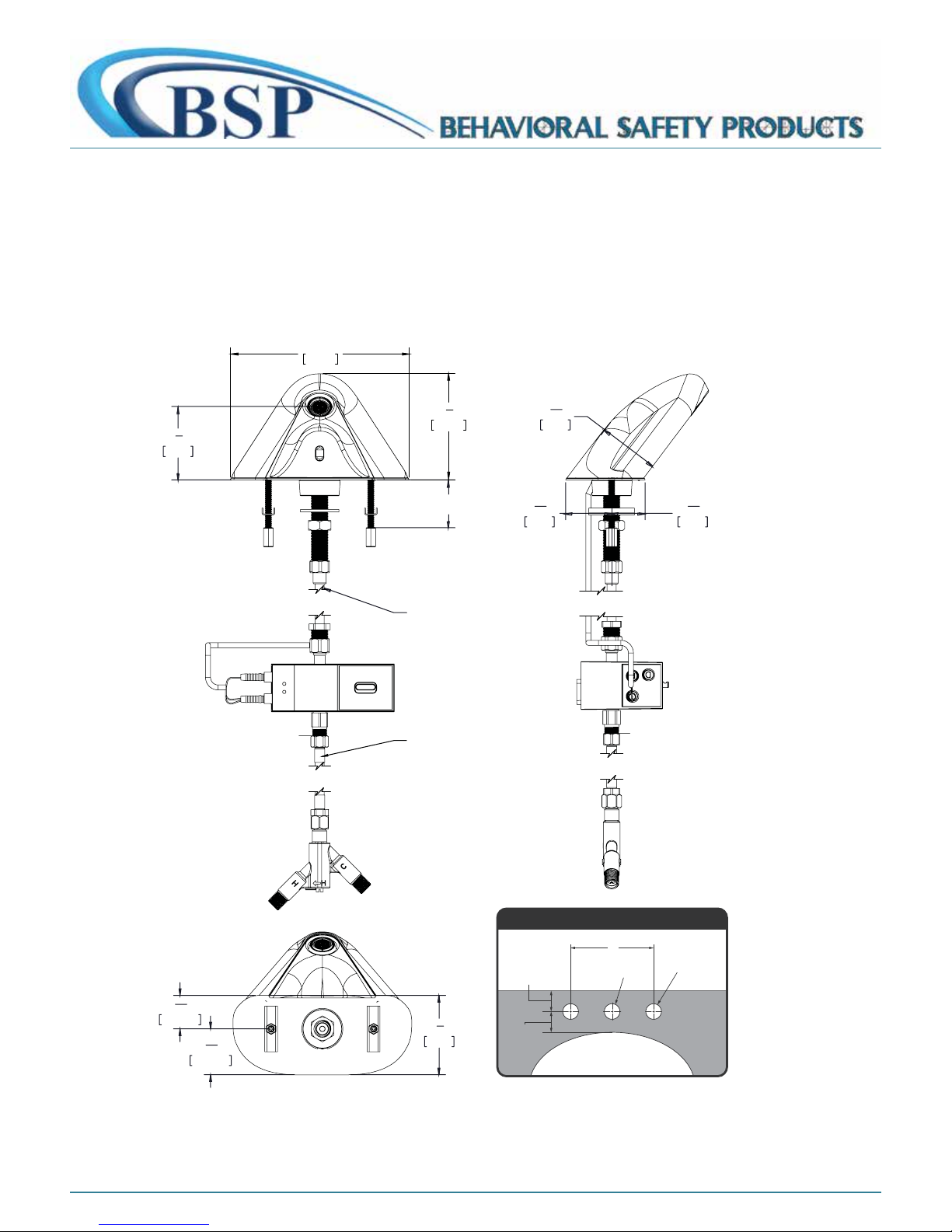
The Faucet comes with a rubber gasket to seat it on the sink. It has a central shank to be connected to the solenoid box or a flex hose.
The Solenoid has an integral battery box or with an optional A/C Adapter wired into a Transformer. The conversion from batteries to
A/C is a quick process. Other optional equipment for mixing hot and cold water can be ordered separately as: TMV (Thermostatic
Mixing Valve).
ROUGH IN DIMENSIONS
7"
177mm
7
2
8
73mm
13
1
16
46mm
5
2
16
60mm
"
"
5
"
1
16
33mm
1
"
4
8
"
105mm
MAX DECK THICKNESS
1.5 INCH
12" FLEX HOSE
12" FLEX HOSE
1
33.19mm
5
16
"
13
1
16
45.50mm
"
706-705-1500
1
3
8
79mm
"
CONTINUED
besafepro.com
Page 3
INSTALLATION INSTRUCTIONS - 1 PAGE 3
2"
MIN. TO LEDGE
[51mm]
3"
MIN. TO WALL
[76mm]
LAVATORY ROUGH-IN
4”
Ø 1-1/8” MIN
[29mm]
Ø 1-1/8” MIN
[29mm]
(TYP.)
IMPORTANT
• Do not over-tighten any connections or damage may occur.
• Be sure to read instructions thoroughly before beginning installation.
TOOLS AND SUPPLIES:
Phillips
Screwdriver
Adjustable
Wrench
Pencil
Drill
Flat Tip
Screwdriver
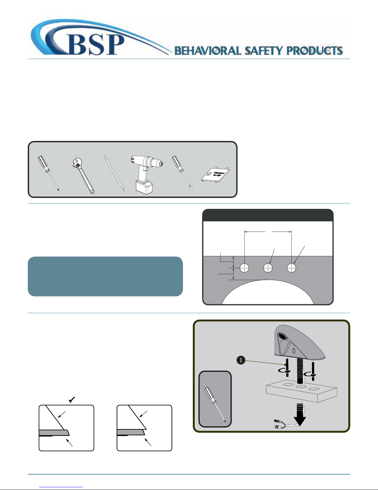
❶ A sink top with 4” on center holes (outer hole centerline to
outer hole centerline) is required for proper installation. Ensure
that there is a minimum of 3” from the centerline of the holes to
the back wall or back of sink.
NOTE
Faucet is designed to be installed on a DECK with a flat surface.
Optional 8" Cover Plate (SF373) is available.
See "OPTIONS" section on Page 1
❷ Install Threaded Mounting Posts ❶ to Faucet body
and tighten with Phillips Head Screwdriver. Insert the wire
connections through the center hole in mounting surface,
followed by the Faucet Shank. Take extra precautions to avoid
pinching any wires. Once Faucet is positioned, verify that the rear
of Faucet is properly resting on the rubber base gasket and does
not overlap the rubber base gasket.
Aerator
Wrench
(included)
Phillips
Screwdriver
CORRECT
706-705-1500
FAUCET
BASE
INCORRECT x
FAUCET
BASE
CONTINUED
besafepro.com
Page 4
INSTALLATION INSTRUCTIONS - 2 PAGE 4
Adjustable
Wrench
Adjustable
Wrench
TOWARDS
REAR
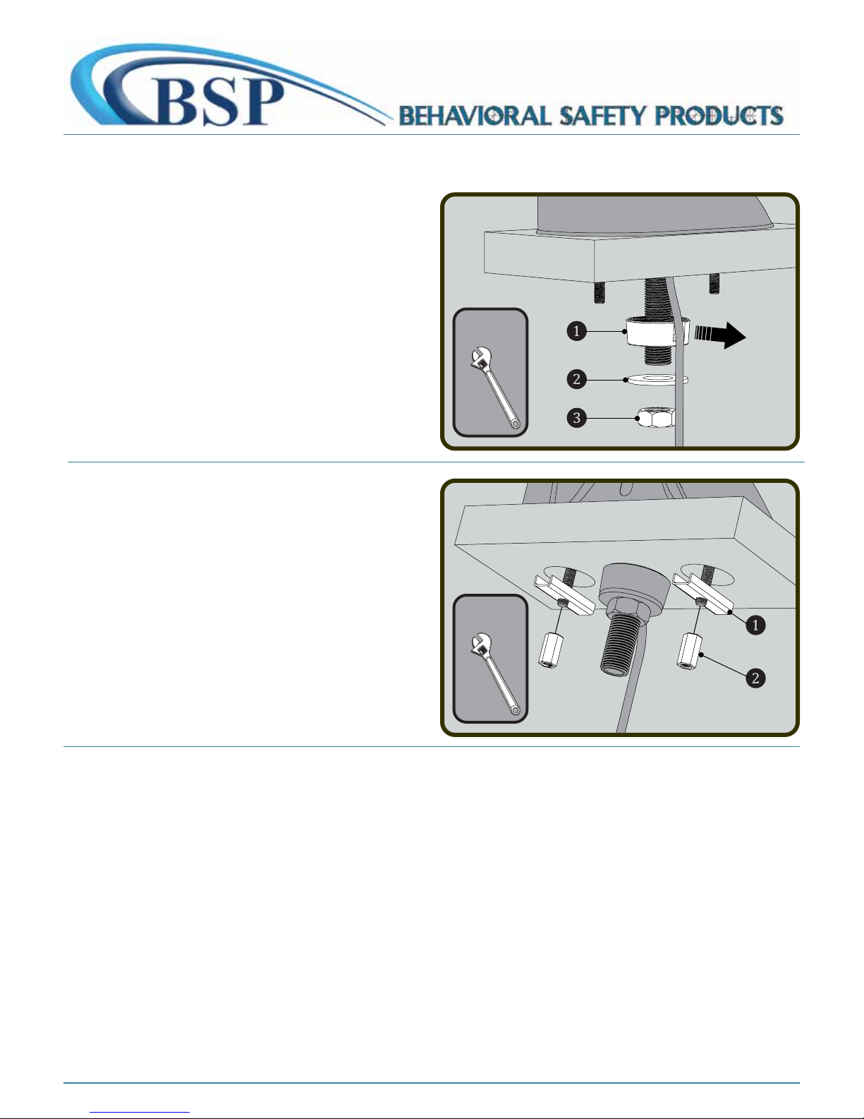
❸ From beneath, install Rubber Wire Guard ❶ (with notch
facing towards rear) over the shank and pass the Sensor wires
through the notch to prevent pinching of wires. Install Metal
Washer ❷ and Mounting Nut ❸ onto shank. Hold Faucet in
position and wrench tighten Mounting Nut ❸. Verify that Sensor
wires are not pinched.
❹ From beneath, install “U” Washers ❶ onto the Threaded
Mounting Posts and secure with the Mounting Nuts ❷. Ensure
that the “U” Washers ❶ are perpendicular to the wall surface for
added leverage and wrench-tighten.
You can mount your Solenoid Box directly to the shank of the
Faucet or use the included Flex Hose and secure the Solenoid Box
onto the wall for more flexibility.
For Direct Connection, please refer to Option 1.
For Flex Hose Connection, please refer to Option 2.
Either of the above connection methods will have no impact on
the performance of the SF390.
706-705-1500
CONTINUED
besafepro.com
Page 5
INSTALLATION INSTRUCTIONS - 3 PAGE 5
Adjustable
Wrench
Adjustable
Wrench
Adjustable
Wrench
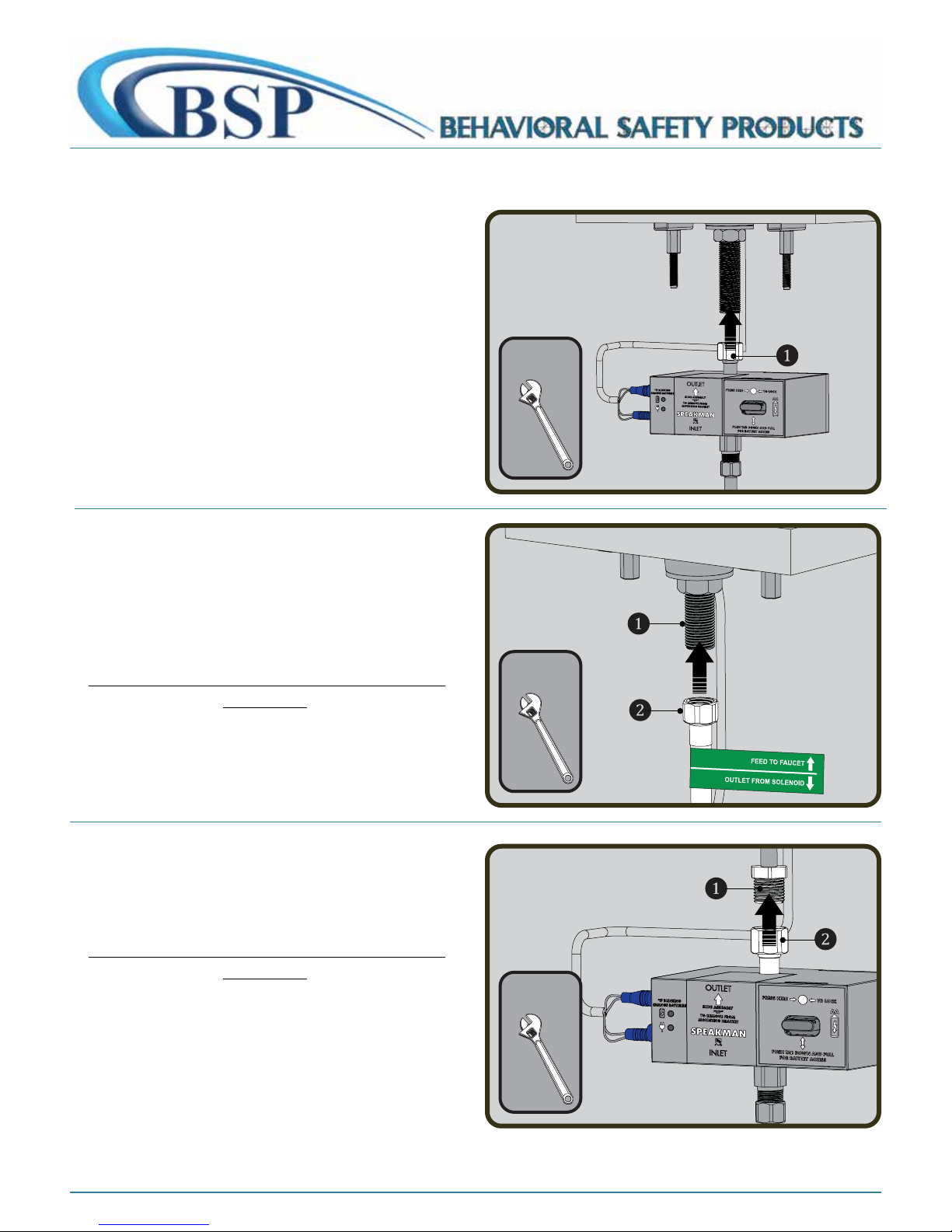
Option 1:
❶ Thread the Solenoid Outlet directly onto the Shank ❶ by
hand. Hold Faucet in position and wrench-tighten the connection.
Option 2:
❶ Should additional space be needed, thread the included
Solenoid Hose ❷ (marked with GREEN label) to Inlet Shank
❶ by hand. Hold Faucet in position and wrench-tighten the
connection.
DRY CONNECTION ONLY. DO NOT USE ANY SEALANT ON THIS
CONNECTION.
Option 2:
❷ Install remaining end of Hose ❶ to the "OUTLET"
connection ❷ of Solenoid. Wrench tighten.
DRY CONNECTION ONLY. DO NOT USE ANY SEALANT ON THIS
CONNECTION.
706-705-1500
CONTINUED
besafepro.com
Page 6
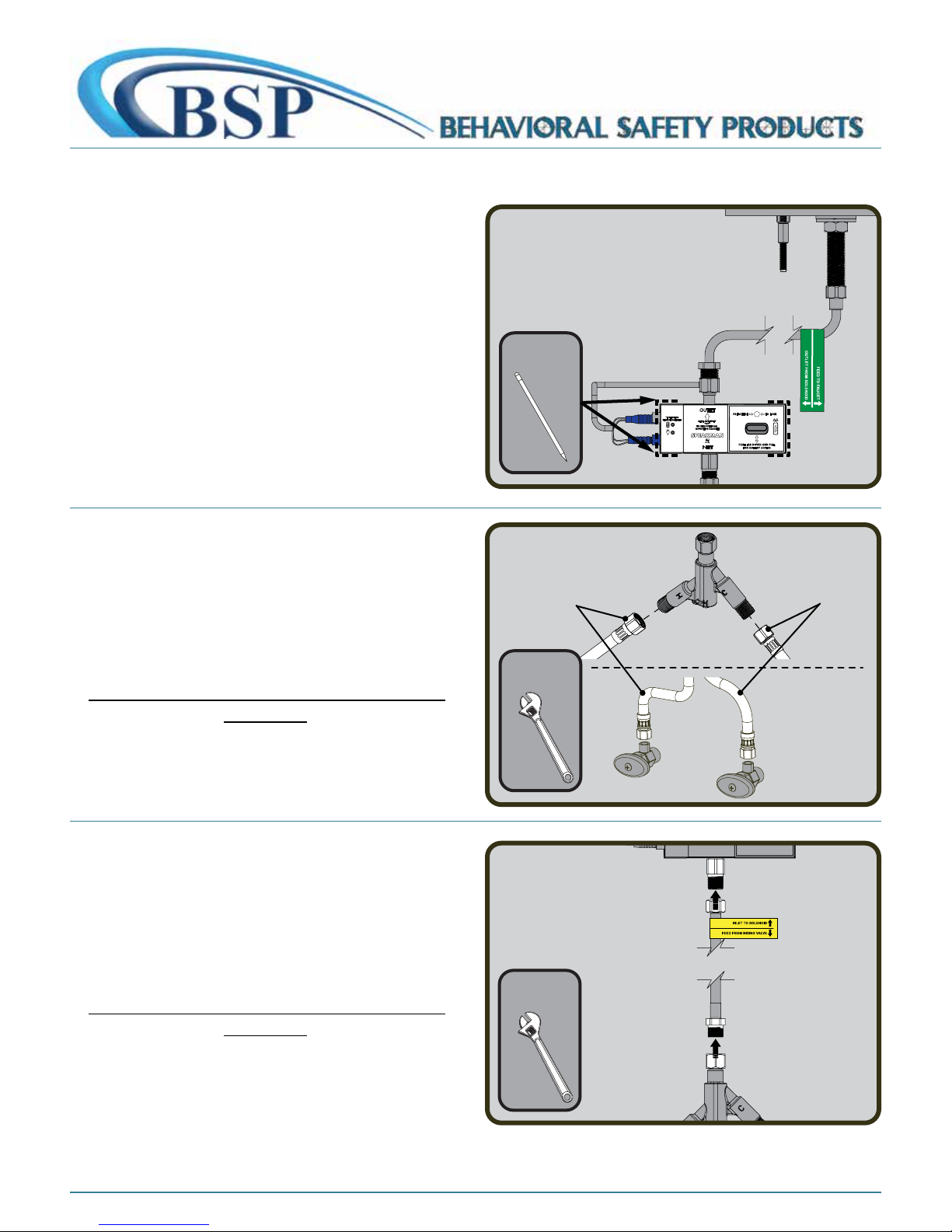
Option 2:
Adjustable
Wrench
HOT
9/16-24 UNEF
(3/8” Compression)
COLD
9/16-24 UNEF
(3/8” Compression)
Adjustable
Wrench
Pencil
❸ Place the Solenoid Assembly against the desired mounting
surface while ensuring adequate clearance for servicing of all
connections. If using the optional A/C Adapter (not supplied),
consider the distance to the nearest electrical outlet. Solenoid
Assembly should be mounted so the inlet and outlet ports are
aligned vertically. Mark location of Solenoid Assembly on the
mounting surface using a pencil.
❻ Make water connections between the Shut Off Valves
and the Under Counter Mixer (UCM) using 3/8" Compression
style hoses (not included). Ensure that the COLD supply hose is
connected to the "C" port on the UCM, and the HOT supply hose
is connected to the "H" port. Wrench-tighten connections. Take
care to not over tighten connections or damage may occur.
PAGE 6INSTALLATION INSTRUCTIONS - 3
DRY CONNECTION ONLY. DO NOT USE ANY SEALANT ON THIS
❼ Thread the Under Counter Mixer (UCM) ❶ to the male
connection of the 12in flex hose ❷ (marked with Yellow label).
Position inlets of UCM so they are accessible. Connect remaining
end of YELLOW labeled hose to the Inlet of the Solenoid. Wrench
tighten connections. Take care to not over tighten connections or
damage may occur.
DRY CONNECTION ONLY. DO NOT USE ANY SEALANT ON THIS
CONNECTION.
CONNECTION.
706-705-1500
CONTINUED
besafepro.com
Page 7
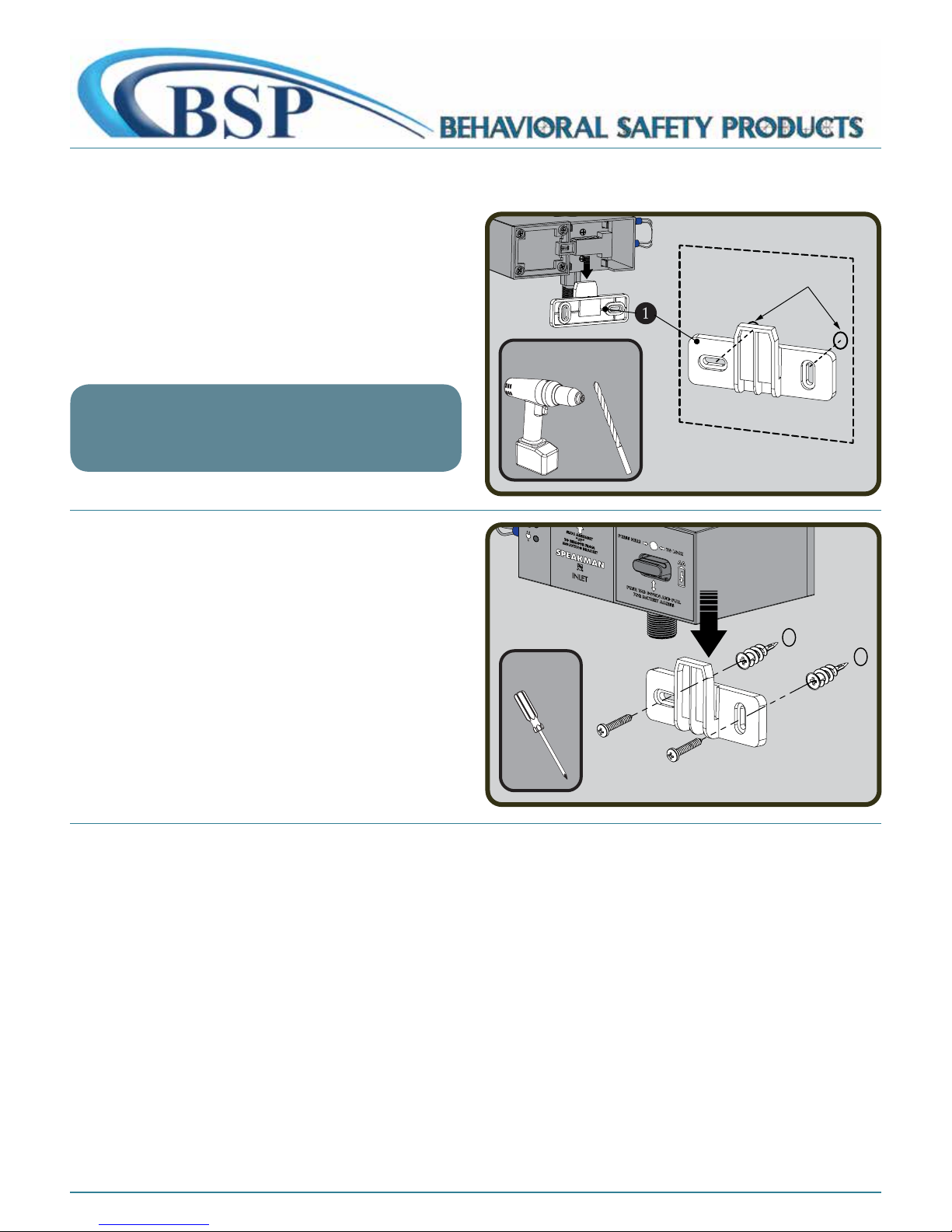
❽ Remove Mounting Bracket ❶ from Solenoid Assembly.
Drill Drill Bit
Phillips
Screwdriver
Using the previously marked location on mounting surface,
align Mounting Bracket ❶ horizontally to approximate position
and mark the mounting locations with a pencil. If mounting
on drywall and not to stud, use the appropriate anchors and
fasteners for application. Recommend screw in easy anchor or
equal for drywall.
IMPORTANT NOTE
When a P-Trap Cover is being used, ensure that the Solenoid
Assembly fits within the P-Trap Cover when mounted. Verify that
all hoses are free from bends or kinks.
❾ After securing the Bracket to the mounting surface, align
and slide Solenoid Assembly over Mounting Bracket.
PAGE 7INSTALLATION INSTRUCTIONS - 4
706-705-1500
CONTINUED
besafepro.com
Page 8
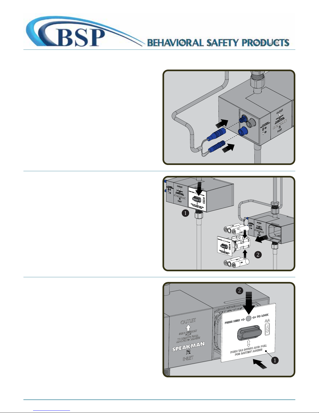
❶ Make electrical connections from the Sensor Eye to the
Solenoid Assembly. Connect the Blue Male Ended Wire to the
Female Connection. Connect the Blue Female Ended Wire to the
Male Connection. To further aid proper alignment, there are white
alignment lines on the connector ends. These alignment lines
should face forward when properly installed.
❷ Access the interior Battery Enclosure by pressing down
on the tab to release the tray holding the batteries ❶. Pull
out battery tray ❷. Insert or replace the batteries with six (6)
new standard 1.5v AA batteries. Ensure the position of the new
batteries are aligned to the plus (+) and minus (-) symbols within
the battery holder.
PAGE 8ELECTRICAL CONNECTIONS
❸ Reinstall the Battery Enclosure to the Solenoid Body ❶.
Make sure to press the indicated location until the battery door is
fully seated and locks into position ❷.
706-705-1500
CONTINUED
besafepro.com
Page 9
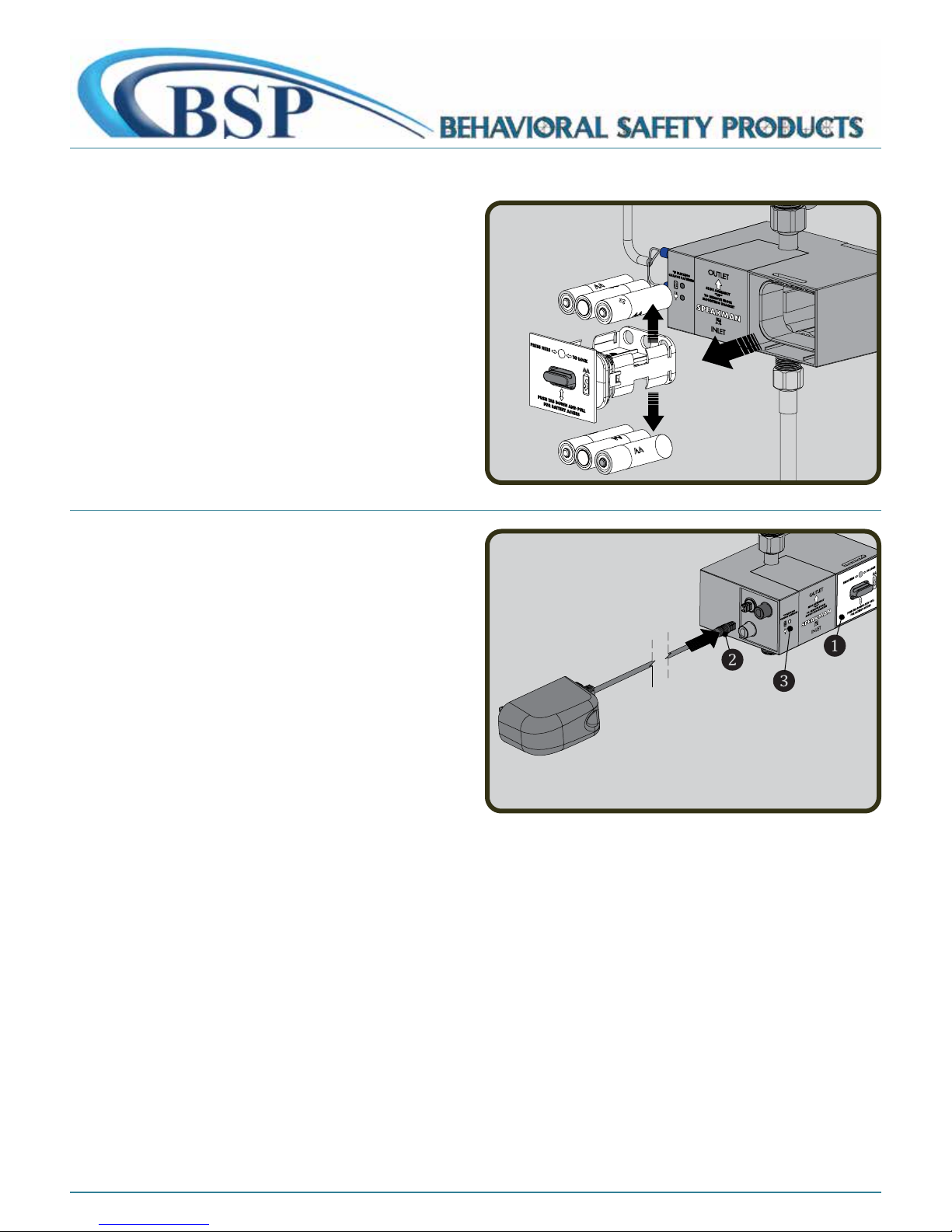
CONVERSION TO A/C POWER
❶ If you wish to change your Faucet to A/C power, remove
batteries from enclosure as shown.
❷ Reinstall the Battery Enclosure to the Solenoid Body ❶.
Connect the A/C Adapter to the Solenoid Body ❷. Plug the A/C
Adapter into the wall outlet. The A/C light ❸ should illuminate.
PAGE 9
706-705-1500
CONTINUED
besafepro.com
Page 10
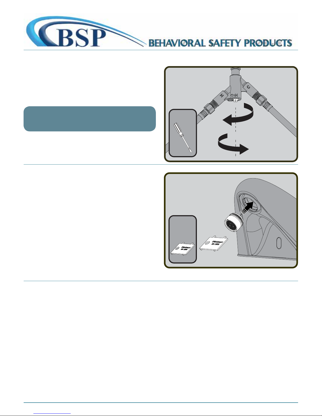
TEMPERATURE ADJUSTMENT AND FLUSHING
Aerator
Wrench
(included)
Flat Tip
Screwdriver
COLDER
HOTTER
❶ Turn on water supplies and check for leaks. Activate Sensor
and allow Faucet to run for 1 minute to flush out any debris.
Adjust the outlet water temperature by rotating the adjustment
screw on the Under Counter Mixer (UCM).
NOTE
If the temperature is still too cold after adjustment, switch the
HOT and COLD lines on the mixer.
❷ Install the Vandal-Resistant Laminar Flow Outlet to the
Faucet using the included Aerator Wrench.
PAGE 10
706-705-1500
CONTINUED
besafepro.com
Page 11
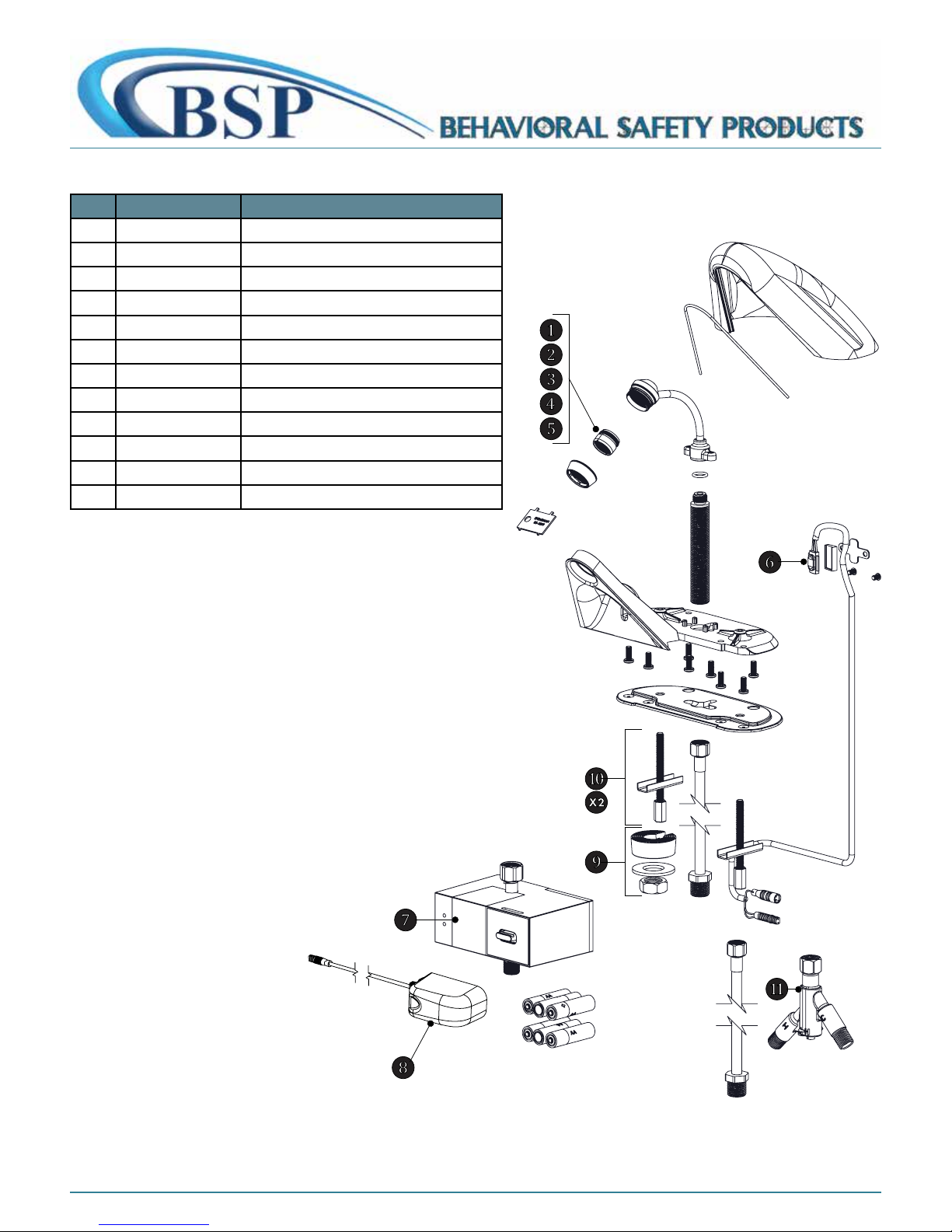
ITEM PART NO. DESCRIPTION
1 RPG05-0851-PC 13/16 – 1.5 GPM Laminar Outlet repair group
2 RPG05-0792-PC 13/16 – 2.2 GPM Laminar Outlet repair group
3 A-ELF 13/16 – 1.2 GPM Laminar Outlet repair group
4 A-EA12 13/16 – 1.2 GPM Aerator Assembly
5 RPG38-0128-PC 13/16 – 0.5 GPM Boca repair group
6 RPG76-107258 Laser Sensor Module
7 RPG76-108469 Solenoid Assembly with Battery Pack
8 RPG76-107259 A/C Conversion Kit (120VAC to 6VDC)
9 G05-0650 Low Profile Spout Mounting Parts
10 G66-0193 Mounting Hardware Group
11 RPG20-2024-CA Under Counter Mixer
12* SF372 Thermostatic Mixing Valve
NOTE: ITEM MARKED IN * NOT SHOWN
PAGE 11REPAIR / REPLACEMENT PARTS
706-705-1500
besafepro.com
Page 12

CARE & CLEANING
• Your SENSORFLO® Faucet is designed and engineered in accordance with the highest quality and performance standards. With
proper care, it will provide years of hygienic and trouble-free service.
• Periodically, the Faucet will require some minor maintenance to keep it at peak performance. There are 2 low battery indicator
lights. One located on the Sensor on the Faucet body and the other located on the Solenoid Box. When the low battery light on the
Sensor blinks, it indicates that the battery is low. However, the Solenoid can still function at this point. When the low battery light on
the Solenoid blinks, the Solenoid will stop functioning at this point and the batteries need to be replaced immediately. To replace
the batteries, follow the installation instructions in the electrical connections section of this document.
• Periodically clean the In-Line Filter.
• The polished chrome finish of your Faucet should be cleaned using mild soap and warm water.
• Dry immediately with a soft, clean cloth for best results.
• NEVER use abrasive cleaners, chemicals, alcohol or other solvents. They may damage the surfaces of the non-chrome plated finishes.
PAGE 12
WAIVER & DISCLAIMER
This waiver-disclaimer is attached to and made a part of the written contract to purchase these products for use in psychiatric and correctional
facilities. Such fixtures and products are purchased to reduce the risk of self-imposed death or injury to patients or clients in such facilities, but are
NOT represented as able to prevent such death or injury.
Behavioral Safety Products, LLC (“BSP”) as the seller and Speakman Company as the manufacturer of these products have not, and will not
represent or warrant to the purchaser shown in this contract (“Purchaser”) that its fixtures and products will prevent death or injury in any case
whatsoever.
BSP and Speakman Company make no express or implied warranty with respect to the preventative quality of its products, but merely represent
that the use of such products tends to reduce deaths and injuries by patients or clients who are subject to meticulous screening processes and
diligent supervision on the part of the facility housing them.
Purchaser acknowledges the foregoing disclaimer and waives any and all claims against BSP and Speakman Company as to express or implied
warranties of fitness for any purpose whatsoever.
IMPORTANT
• This fixture must be mounted with its back to a wall.
• It is unsafe if the unit could be accessed from the back side.
• All plumbing and electrical connections under the sink are not ligature resistant and should be in a separate enclosure or cabinet
(not supplied).
706-705-1500
CONTINUED
besafepro.com
Page 13

PAGE 13TROUBLESHOOTING
Before calling Behavioral Safety Products for service, please run through the following checklist:
If water flow from the Faucet decreases
1. Make sure the supply stops are open.
2. Ensure the Temperature Adjuster of the Under Counter Mixer (UCM) is not in the closed position (to open, screw out the
Temperature Adjuster Screw (counter-clockwise direction).
3. Check that the In-line Filter located in the hose connecting the solenoid and the mixer is not blocked with debris. Remove filter from
the Solenoid Inlet and rinse filter screen with clean water. Reassemble the filter, open stops, and check water flow. Stops must be
turned off when filter is removed.
4. Remove the Laminar Flow Outlet from the spout using the outlet wrench. Operate the Faucet with outlet device removed. If water
flow is acceptable, disassemble the outlet device and rinse components with clean water.
5. If the above steps do not resolve the problem; call Behavioral Safety Products (706-705-1500) for assistance.
If no water flows from the Faucet, and
If you can hear a clicking sound of Solenoid opening, but no water flows
1. Verify that the HOT and COLD wall stops are completely open.
2. If the Battery Light within the Sensor Eye or Solenoid blinks continuously, even when the Faucet is not in use, the batteries within
the Solenoid have low voltage and need replacement.
3. Verify that the In-Line Filter in the Solenoid is not blocked by debris. Clean filter if needed.
If you do not hear a clicking sound of Solenoid opening and no water flows
1. If the Battery Light within the Sensor Eye blinks continuously, even when the Faucet is not in use, the batteries within the Solenoid
have low voltage and need replacement.
2. Unplug connections to Solenoid for 2 minutes. Plug connections back in. The red light on the Sensor should turn on for several
seconds before becoming operational. If not, check power supplies and connections.
3. Disconnect the existing Solenoid Assembly and connect a new Solenoid Assembly. Activate the Sensor and check for water flow. If
the water flows, the existing Solenoid Assembly should be replaced.
If the batteries have been replaced, but the Faucet still does not operate:
1. Check the battery polarity and electrical connections. Make sure all electrical connections are fully inserted.
2. If the Faucet does not operate, replace the existing Solenoid Assembly with one you know to be functioning.
If the Faucet activates, but the water will not shut off
1. Hold a hand in front of the Sensor at up to 7" away for more than 1 minute until the water flow stops. Once the water stops, remove
your hand and wait 60 seconds. Then place your hand in front of the Sensor and verify that it is operating properly.
2. If the Faucet still does not shut off, cover the front of the sink with a towel. This will eliminate the potential of reflections activating
the Sensor.
3. If it is a new installation and still not working, replace the Solenoid Assembly.
706-705-1500
CONTINUED
besafepro.com
Page 14

QUESTIONS & ANSWERS
Q. How does the Sensorflo® Faucet work?
A. It uses laser technology. The Sensor emits a non-visible beam of light. When an object enters the detection area, the Sensor signals
the Solenoid Valve to open for water to flow. When an object leaves the detection area, the Sensor signals the valve to close.
Q. Is the Sensorflo® Faucet sensor beam adjustable?
A. No, the Sensorflo® Faucet sensor beam is not adjustable. It has been factory set to factory specifications for these Faucets.
Q. What about water conservation?
A. The Sensorflo® design directly addresses water conservation. Water savings of up to 85% are not unusual. Additional energy savings
are realized by conserving hot water.
Q. Can the water temperature of the Sensorflo® Faucet be adjusted?
A. Yes, this Faucet has a hot and cold water mechanical mixing valve. If you need to meet ASSE 1070, you must use our TMV
(Thermostatic Mixing Valve) option.
Q. Does Sensorflo® reduce maintenance?
A. By elimination of on/off handles, control components are reduced and fittings stay cleaner longer. Only a light rinsing and wiping
is required to restore the beauty of the Sensorflo® Faucets. Drip stains are eliminated. Fingerprints and soap spots on sinks and fittings
are avoided. Finishes last longer and wash areas stay cleaner. Germs and bacteria are not transferred as easily making for a healthier
environment.
PAGE 14
Q. The chrome finish on my Faucet seems to be deteriorating. What can I do to prevent this from happening?
A. Many commercial cleaning products contain harsh chemicals and abrasives. These products should not be used on any chromeplated plumbing products. Please use only mild soap and water to clean the Faucet. Dry immediately with a soft cloth.
Q. Does the Sensorflo® system shut off immediately when an object leaves the sensing area?
A. A very short delay of approximately 0 to 1.5 seconds occurs before water is shut off.
Q. Is there a way to adjust the flow of water?
A. The temperature adjusters can be used to control the flow of water.
Q. Is my Faucet protected from power surges?
A. Yes, Sensorflo® has been designed to have built-in power surge protection.
Q. If we lose power, do I have to do something to get the Faucet to operate again?
A. After a power outage, the Faucet is automatically ready for operation as soon as the power comes back on.
Q. If I call a plumber to come and install this Faucet, will they know enough to hook it up?
A. Our installation diagrams are very easy to follow.
706-705-1500
besafepro.com
 Loading...