

Page 1

Table of Contents
1. Introduction ………………………………………………. 1
2. Safety note ……………………………………………..… 2
3. Explanation of Controls and
Indicators …………………... 3
3-1. Product illustration ……………………………………….
3
3-2. Functional push button …………………………………….
4
3-3. LCD display ………………………………………………. 5
4. Specification ………………………………………………. 6
4-1. General Specification ……………………………………...
6
4-2. Electrical Specification ………………………………….
7- 9
5. Measurement operation …………………………………..
9
5-1 DC voltage & AC voltage
measurement ………………... 9
5-2. Resistance
measurement …………………………….….. 10
5-3. Diode & Continuity
check ………………………..…..… 10
Page 2

5-4. DC/AC ¸ A or mA measurement ………………….…….
11
5-5. DC/AC 10A measurement …………………………..….
12
5-6 Temperature
measurement ………..…. 12
6. Maintenance ……………………………………………….
12
6-1. Replacing the battery …………………………...……….
12
6-2. Replacing the fuse ……………………………………….
12
6-3. Cleaning and
Decontamination …………………………. 13
1. Introduction
This Meter is a handheld and battery operated Digital Multi
Meter(DMM) with multi function. This Meter is designed to
meet IEC61010-1 & CAT II 600V over voltage category and
double insulation. The meter with holster that is giving the
main body, though downsized, high resistance against the
shock of a drop.
This operating instruction covers information on safety and
caution. Please read relevant information carefully and
observe all the warnings and note strictly.
The DMM as general measurement tool and widely used in
the school, laboratory, factory and other social field.
Page 3
2. Safety note
Warning
To avoid possible electric shock or personal injury and to
avoid possible damage to the meter or to the equipment
under test, adhere to the following rule:
Do not apply more than the rated voltage, of marked on
the meter, between the input terminal and grounding
terminal..
Do not apply voltage between COM and OHM terminal,
in the resistance measuring state.
Do not measure current with test lead inserted into
voltage or OHM terminal.
Do not expose the instrument to the direct sun light,
extreme temperature and humidity or dew full.
Inspect the test lead for damaged insulation or exposed
metal.
Before measuring current, check the Meter”s fuses and
turn off power to the circuit before connecting the meter
to the circuit.
Disconnect circuit power and discharge all high voltage
capacitors before testing continuity, diode, resistance,
capacitance or current.
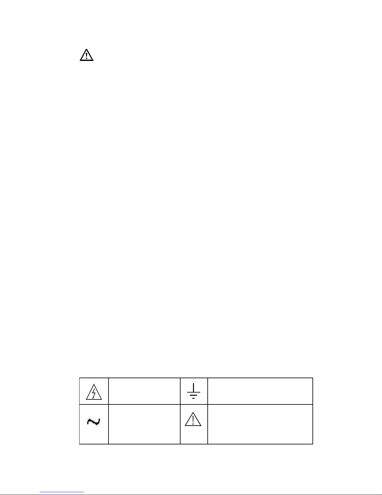
Note international Electrical Symbol.
Dangerous
Voltage
Ground
AC
Alternating
current
Warning
see explain in manual
1
Page 4
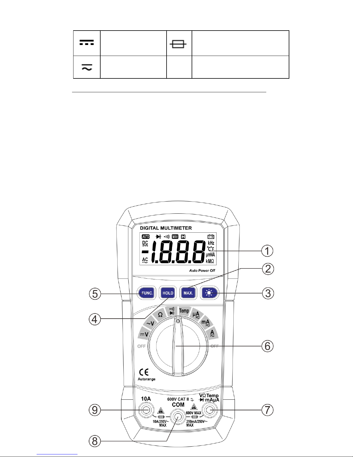
DC (Direct
Current)
Fuse
AC or DC
Measurement category(over voltage category):
This instrument is meet the safety condition of CAT II.
The equipment is used for measurement in building
facilities. Examples are measurements on distribution
boards, circuit breaker and industrial equipment
located in fixed facilities, as a fixed motor.
3. Explanation of controls and indicators
3-1. Meter illustration
2
Page 5

Fig. 1 Exterior view
1. LCD display 2. ‡ MAX· push button 3. ‡ BACK LIGHT·
push button 4. “HOLD· push button 5. ‡ FUNC· Push
button 6. Rotary Switch (Knob) 7. ‡ V/Ω
/uA/mA/Temp· Input terminal
8. ‡ COM· input terminal 9. ‡ 10A· input terminal
3-2. Functional push button
Push
button
Function
Func
“FUNC” key is the function select key
that acts with trigger. Use the key as
switch of DC/AC current,
Diode/Continuity and ₤ /₦ .
HOLD
Press “HOLD· to enter and exit the hold
mode in any mode. That act with trigger.
MAX
This key is act with trigger. Press this key
once, the maximum value is holding (Will
displays “MAX’ symbol in the LCD).
After pressing the key, A/D will keep
working, and the display value are always
up dated and kept the maximum value.
NOTE: The actual gained value is not the
peak value.
3
Page 6
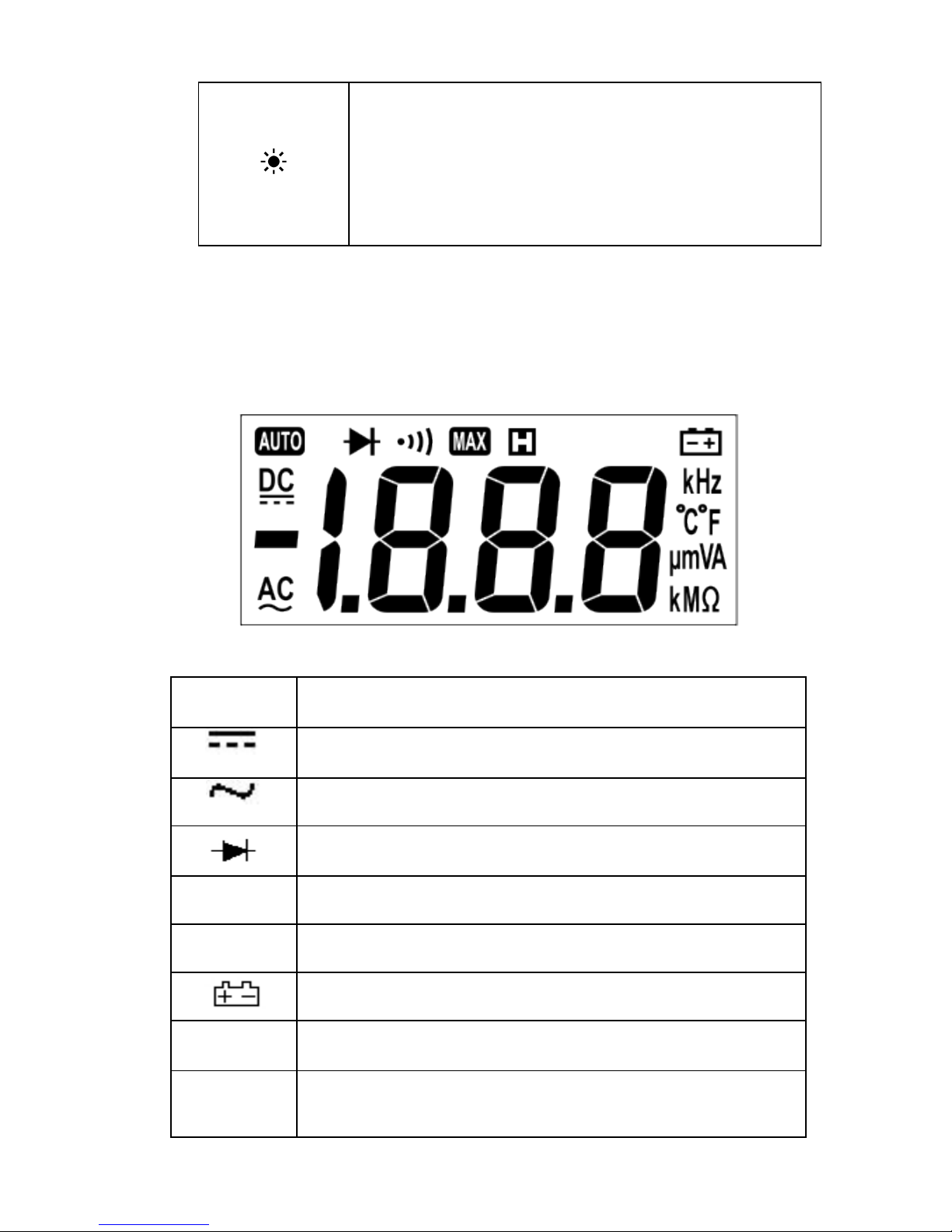
This key is used control Backlight. This key
is act with trigger. When press and hold
the key over 2 sec, will enable Backlight.
Press the key again , the backlight will
disable.
3-3. Display indicators
Fig. 2 LCD
Indicator Meaning
DC voltage or current
AC voltage or current
Diode
MAX Maximum value
HOLD Data hold
Low battery indicator
MKέ έ Kέ Mέ is unit of resistance
₤ /₦
The unit of temperature
(₤ : Centigrade; ₦ : Fahrenheit)
4
Page 7

¸ mVA
mV ,V is unit of voltage
¸ A, mA, A is unit of current
1 Indicate negative reading
4.Specification
4-1. General Specification
◤ Auto ranging DMM , that full scale is 2000 counts
◤ Display : 3 1/2 digit LCD display..
◤ Over load protection: Used the PTC protection circuit for
Resistance, temperature measurement.
◤ DATA HOLD function
◤ MAX value hold function
◤ Back Light
◤ Low battery indication
◤ Auto Power OFF. : If the meter is idle for 15 minutes (idle
time), the meter automatically turns the power off. After
auto power-off, pushing any of the push button or
changing the rotary switch can turn on the meter again.
NOTE: ,1-After auto power off in the AC mode, if changing
the rotary switch to the DC mode, the
Re-power on if disabled.
(2) The meter enters sleep mode after Auto power
off. If press ‡ HOLD· push button to re-power
on in the sleep mode, the auto power off
function is disabled.
◤ Operating temperature & Humidity:
0 ~ 40₤ (32 ~104 ₦ ) & < 80% RH
◤ Storage temperature & Humidity:
-10 ~ 50₤ (14 ~ 122 ₦ ) & <70%RH
◤ Power Supply: 9V Battery(6F22 or 1604A Type) x 1pc.
◤ Safety Class: IEC 61010-1, CAT II 600V.
● Dimension(L x W x H) & Weight:140 x 67 x 30mm, Approx.
5
Page 8

112g
4.1.1 Accessory :
1. User”s Manual ---------------------------- 1pc
2. Test lead ---------------------------- 1set
3. 9V Battery --------------------------- 1pc
4. K-type temperature probe[P3400]---- 1pc
4-2. Electrical Specification ( at 23±5₤ ; <75% RH)
4.2.1 DC Voltage
Range Resolutio
n
Accuracy
200m
V
0.1mV
±,0.5% rdg + 2dgt-
2V 0.001V
20V 0.01V
200V 0.1V
600V 1V ±,0.8% rdg + 2dgt-
* Over load protection: SG(Spark Gap) used to protect that
the voltage overload 1500V
4.2.2 AC Voltage
Range
Resolutio
n
Accuracy
2V
(40Hz-400Hz)
0.001V
±,1.0% rdg + 3dgt-
20V
(40Hz-400Hz)
0.01V
6
Page 9
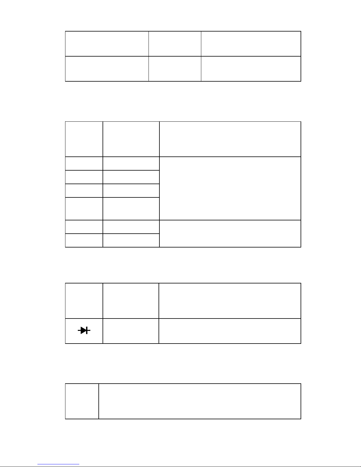
200V
(40Hz-400Hz)
0.1V
600V
(40Hz-200Hz)
1V
±,1.2% -rdg + 3dgt
* SG(Spark Gap) used to protect High voltage that is
over 1500V.
4.2.3 Resistance
Range Resolution
Accuracy
200έ 0.1έ
±,0.8% rdg + 2dgt-
2kέ 0.001kέ
20kέ 0.01kέ
200k
έ
0.1kέ
2Mέ 0.001Mέ
±,1.0% rdg + 2dgt-
20Mέ 0.01Mέ
4.2.4 Diode check
Range
Resolution Function
0.001V
Will display the forward drop
voltage.
* Operating current>about 1mA
* Open circuit voltage>about 1.48V
4.2.5 Continuity
Rang
e
Function
87
Page 10
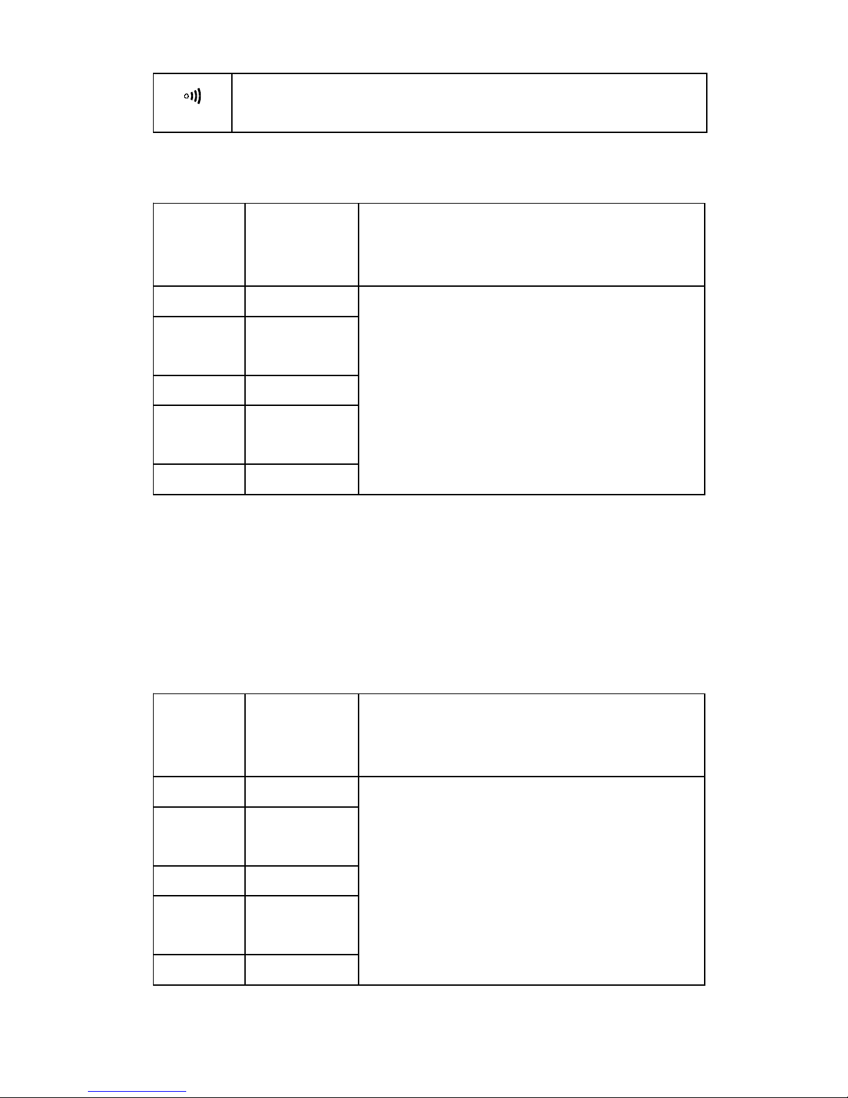
If measured resistance less than 100 έ , will
buzzer is sounded.
* Open voltage: about 0.5V
4.2.6 DC Current
Range
Resoluti
on
Accuracy
200¸ A 0.1πA
±,1.5% rdg + 3dgt-
2000¸
A
1¸ A
20mA 0.01mA
200m
A
0.1mA
10A 0.01A
* Over Load protection> use the fuse(F250mA/250V) at ¸ A
/mA range,
and use the fuse(F10A/250V) at 10A
range.
* Max input current:>250mA at “mA” input terminal and
10A at “10A” input terminal.. .
4.2.7 AC Current [40Hz-400Hz]
Range
Resoluti
on
Accuracy
200¸ A 0.1¸ A
,1.5% rdg + 4dgt-
2000¸
A
1¸ A
20mA 0.01mA
200m
A
0.1mA
10A 0.01A
* Over Load protection> use the fuse(F250mA/250V) at ¸ A
Page 11
/mA range,
and use the fuse(F10A/250V) at 10A
range.
* Max input current:>250mA at “mA” input terminal
and 10A at “10A” input terminal...
* Frequency response>40  ̄ 400Hz
4.2.8 Temperature
You can selecting [₤ ] or [₦ ] by ‡ FUNC· key.
Range -20₤ ~ 1000₤
Resoluti
on
1₤
-20₤ ~0₤
(,5% rdg + 4dgt-
Accuracy 0₤ ~400₤
(,2% rdg + 3dgt-
400₤ ~1000₤
(,3% rdg + 3dgt-
Fahrenheit Temperature [₦ ]
Range 0₦ ~1800₦
Resoluti
on
1₦
-0₦ ~50₦
(,5% rdg + 4dgt-
Accuracy 50₦ ~750₦
(,2% rdg + 3dgt-
750₦ ~1800₦
(,3% rdg + 3dgt-
5. Measurement operation
5-1 DC & AC voltage measurement
Warning:
To avoid harms to you or damage to the meter from
electric shock. Please do not attempt to measure
voltage higher than DC/AC 1000V although readings
may be obtained.
The DC voltage range are 200.0mV, 2.000V, 20.00V ,
9
Page 12

200.0V and 600V and then. The AC voltage ranges are
2.000V, 20.00V, 200.0V and 600V.
To measure DC or AC voltage:
④ Insert the red test lead into the ‡ VΩ· input terminal
and the black test lead into the COM terminal.
⑤ Set the rotary switch to DC or AC range.
⑥ Connect the test lead across with the object under
testing.
The measured value will be show on the LCD
display.
Note:
When DC or AC voltage measurement has been completed,
disconnect the connection between the testing lead and the
circuit under testing.
5-2. Resistance measurement
The resistance range are: 200.0έ , 2.000Kέ ,20.00Kέ ,
200.0Kέ , 2.000Mέ .20.00Mέ .
To measure resistance, connect the meter as follows:
④ Insert the red test lead into the · VΩ· terminal and
the black test lead into the COM terminal.
⑤ Set the rotary switch to proper resistance range..
⑥ Connect the test lead across with the object under
testing.
The measured value will be show on the LCD display.
Note:
◤ The test lead can add 0.1 έ to 0.2 έ of error to
resistance measurement. To obtain precision reading
in low-resistance measurement, that is the range of
200.0έ , short the input terminal before measuring.
In this time, the contact resistance displayed on the
LCD. You can subtract the contact resistance value
from the measured value.
Page 13

◤ For high-resistance measurement (>10M έ ), it is
normal taking several second to obtain stable
reading.
◤ The LCD display ‡ OL· indicating open-circuit for the
tested resistor or the resistor value is higher than the
maximum range of the meter.
5-3. Diode/Continuity check
5.3.1. Diode
④ Set the rotary switch to ‡ · position. First time,
default mode is diode check mode. You can enter the
continuity check mode by the ‡ FUNC· Key.
⑤ insert the red test lead into the “VΩ” terminal and the
black test lead into the ‡ COM· terminal.
⑥ Use the diode test mode to check diodes, transistors
and other semiconductor device. In the diode test
mode sends a current through the semiconductor
junction, and the measure the voltage drop across the
junction. A good silicon junction drop between 0.5V
and 0.8V.
⑦ For forward voltage drop reading on any
semiconductor component, place the red test lead on
the component anode and place the black test lead on
the component cathode. The measured value show on
the display.
⑧ Reverse the test lead and measure the voltage across
the diode again.
◤ If diode is good, the display shows ‡ OL· .
◤ If diode is shorted, the display shows 0 in both
direction.
◤ If display shows ‡ OL· in both direction, the diode
is open.
5.3.2. Continuity Check:
10
Page 14

④ Press the ‡ FUNC· key to enter to the continuity mode.
⑤ The buzzer sound if the resistance of a circuit under
test is less than 100έ .
5-4. DC/AC µA or mA measurement
DC Current range is 200.0¸ A/2000¸ A and
20.00mA,/200.0mA and then 10A range.
AC Current range is 200.0¸ A/2000¸ A and
20.00mA,/200.0mA and then 10A range.
④ Turn off power to the circuit. Set the rotary switch
to the proper DC/AC ¸ A or DC/AC mA position.
⑤ Break the current path to be tested. Connect the
red test lead to the more positive side of the break
and the black test lead to the more negative side of
the break.
⑥ Turn on power to the circuit. The measured value
show on the display.
5-5. DC/AC 10A measurement
④ Insert the red test lead into the input terminal
marked as ‡ 10A· .
⑤ The measuring procedure is same as that of 5-4
section..
Note:
◤ For safety”s sake, the measuring time for high current
should be ≧ 10 second for each measurement and the
interval time between two measurement should be
greater than 5 minutes.
◤ When current measurement has been completed,
disconnect the connection between the testing lead and
the circuit under test.
5-6. Temperature measurement
To measuring temperature should be use the K-type
11
Page 15

probe :P3400.
④ Set the rotary switch to the ‡ TEMP· range. In this
time, The environment temperature value displayed
on the LCD.
⑤ Insert the K-type probe to the two ‡ COM· and
‡ TEMP· terminals. The two ‡ +· and ‡ -‡ pins of
temperature probe(P3400) must be direct at the
‡ COM· & ‡ ₤ · terminal respectively.
⑥ The measured temperature value will be displayed on
the LCD.
6. Maintenance
6-1. Replacing the battery
When meter display the battery must be replace
to maintain normal operation.
④ Disconnect and remove all test probes from any live
source and meter.
⑤ Open the battery cover on the bottom case by
screwdriver.
⑥ Remove old battery and snap new one into battery
holder
6-2. Fuse replacement
Replacing the defective fuse should the done
according to the following procedure.
④ To avoid electrical shock, remove the test lead and
any input signal before opening the bottom case.
⑤ Open the button case and then remove the
defective fuse and insert a new fuse of the same size
and rating.
⑥ Replace the bottom case and reinstall all the screw.
6-3.Cleaning and Decontamination
The meter can be cleaned with soft clean cloth to remove
1213
Page 16

any oil, grease or grim. Do not use liquid solvent or
detergent.
 Loading...