

B+S UFWSP, UFWWSP, UFWW-SP-1-CB-LS, UFWW-SP-2-CB-LS, UFWW-SP-3-CB-LS Installation, Operating And Servicing Instruction Manual
...Page 1
1
INSTALLATION, OPERATING AND SERVICING INSTRUCTION MANUAL
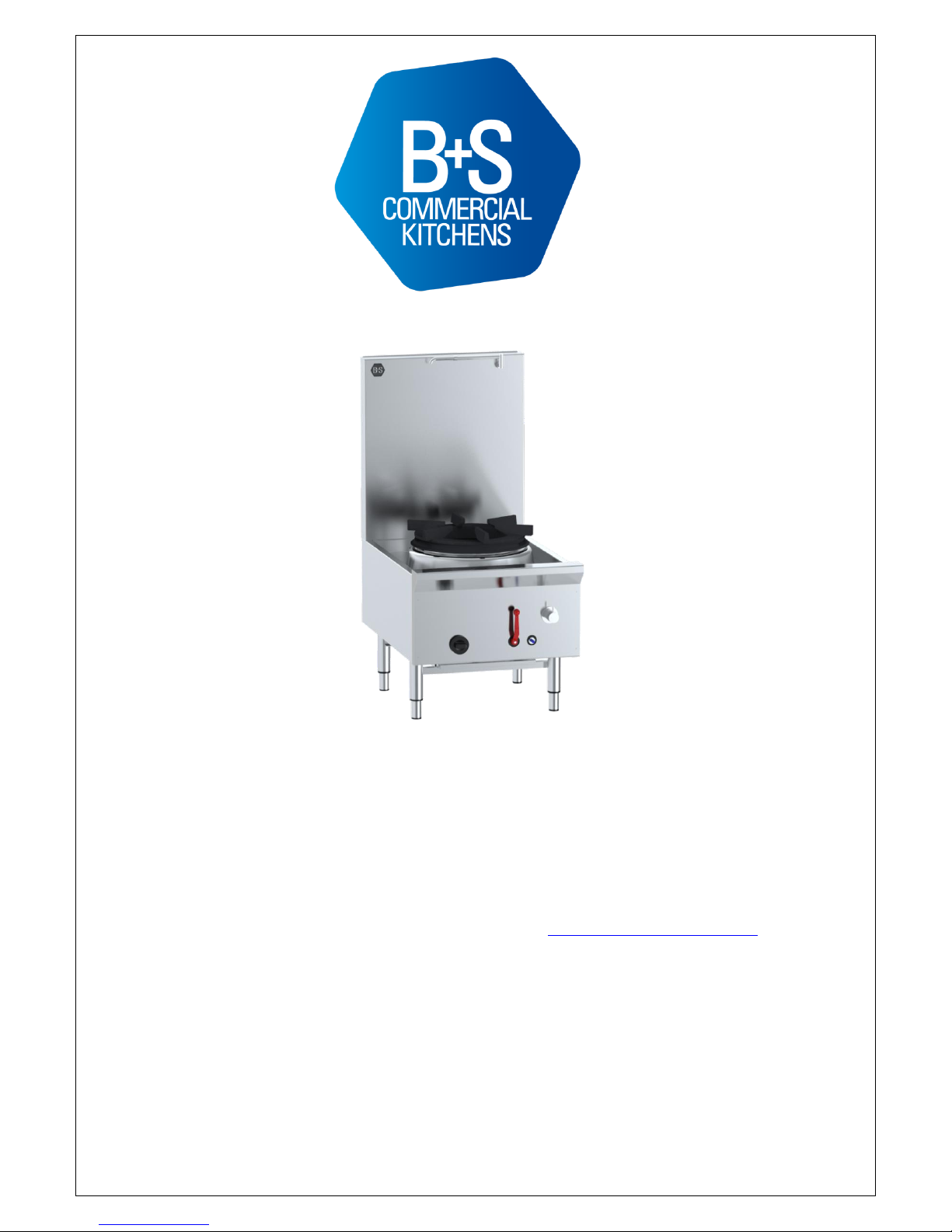
UFWSP & UFWWSP Series Commercial Stock Pot / Boiling Top
Model No’s.: UFW–W–D–SP-1/2/3–CB-LS
Approval No.; GMK10345
Manufactured By;
B&S Commercial Kitchens Pty Ltd
57 Plateau Road Reservoir VIC 3073 AUSTRALIA
Tel: +61 3 9469 4754 Fax: +61 3 94694504 Web: www.bscommercialkitchens.com
Please ensure this booklet is kept in a safe and prominent location for future reference.
The reproduction on or copying of any part of this booklet via any means is strictly forbidden unless agreed to in writing by
the manufacturer.
Owing to continual product development and improvements to its products, B&S Commercial Kitchens Pty Ltd reserves the
right to change the product specifications and design without prior notice.
Page 2

2
Table of Contents
INSTALLATION, OPERATING AND SERVICING INSTRUCTION MANUAL .................... 1
UFWSP & UFWWSP Series Commercial Stock Pot / Boiling Top .................................. 1
Product Specifications & Introduction ............................................................................ 4
IMPORTANT WARNINGS................................................................................................... 5
Table 1: Nominal Terminal Input Rates & Injector Sizes ............................................................................... 5
Table 2: Standard Model General Information ............................................................................................... 5
Figure 1: Plumbing Connections .................................................................................................................... 6
Table 3: Plumbing Connections
...................................................................................................................... 6
Installation Instructions .................................................................................................... 6
Regulations .............................................................................................................................. 6
Data Label ............................................................................................................................... 6
Ventilation ................................................................................................................................ 6
Combustible Surfaces ............................................................................................................. 6
Gas Connection ....................................................................................................................... 7
Pressure Test Point ................................................................................................................. 7
Water Connection .................................................................................................................... 7
Before Leaving - Commissioning ............................................................................................. 7
Operating Instructions ...................................................................................................... 8
IMPORTANT WARNING! .................................................................................................... 8
IMPORTANT WARNING! .................................................................................................... 8
Lighting Instructions ................................................................................................................. 8
Shutdown Procedure ............................................................................................................... 9
Deck Cooking (Water Spray) – Where Fitted (Water Cooled Models) .................................... 9
Telescopic Laundry Arm – Manual Control (Water Cooled Models) ....................................... 9
IMPORTANT WARNING! .................................................................................................... 9
Waterset Automatic Laundry Arm (WokSpout) – Where Fitted ............................................... 9
Telescopic Laundry Arm Operation with Knee Valve – Where Fitted ..................................... 9
IMPORTANT WARNING! .................................................................................................. 10
Page 3

3
Maintenance and Care .......................................................................................................... 10
Servicing Instructions ..................................................................................................... 11
Abnormal Operation .............................................................................................................. 11
Gaining Access to Gas and/or Water System ....................................................................... 11
Removal of Burner for Service .............................................................................................. 11
Pilot and Flame Safeguard .................................................................................................... 11
Adjustments ........................................................................................................................... 12
Servicing WokSpout – Where Fitted...................................................................................... 12
Servicing Knee Valve – Where Fitted .................................................................................... 12
Gas Type Conversion ............................................................................................................ 12
Table 4: Spare Parts List.............................................................................................................................. 13
Table 5: Troubleshooting ............................................................................................................................. 14
Page 4
4
Product Specifications & Introduction
Appliance Name:
UFSP & UFSPW Series Commercial Stock Pot Table
This appliance may be branded as B&S, Kirana and Verro
We are confident that you will be delighted with your B&S stock pot, and that it will become the backbone of
your kitchen. To ensure you receive the utmost benefit from your new B&S appliance, there are
two important things you can do.
1. Ensure you read this booklet carefully and carefully follow the instructions given. Ensure that this
booklet is kept in a safe and prominent location for future reference.
2. Should you be unsure of any aspect of the operation/performance, servicing and installation of the
appliance, please contact your B&S dealer immediately. In most instances a phone call could
answer your question.
Manufactured By:
Certificate Holder:
Model Number/s:
Approval Number:
Gas Types:
B&S Commercial Kitchen s Pty Ltd
57 Plateau Road
Reservoir Victoria 3073
Tel; + 61 3 9469 4754 Fax: +61 3 9469 4504
E-mail: [email protected]
How to read model numbers;
UFW – W – D – SP –1/2/3 – CB – LS - P
UFW = Unflued Table (All Models)
W = Waterless Model – Where Applicable
D = Deluxe Model – Stainless Steel Chassis (where
applicable)
SP = Stock Pot Table
Number of stock pot holes
1 - Single Hole
2 - Two Holes
3 - Three Holes
Burner type/s
CB = Chimney Burner
LS = Low Splashback – Where Applicable
P = Plinth Mount
E.G. UFWW – SP – 2 – CB – LS
Is a waterless stock pot model, with two holes, two chimney burners and
has low height splashback.
GMK10345
Natural Gas and Propane Gas
Page 5
5
IMPORTANT WARNINGS
THIS APPLIANCE SHALL ONLY BE INSTALLED/SERVICED BY
AN AUTHORISED INSTALLER.
THIS APPLIANCE MUST BE INSTALLED IN ACCORDANCE
WITH THE SPECIFIED INSTRUCTIONS AND SPECIFICATIONS.
IMPROPER INSTALLATION OR OPERATION OF THIS
APPLIANCE MAY RESULT IN PRODUCT FAILURE WHICH MAY
LEAD TO PROPERTY DAMAGE, PERSONAL INJURY OR
DEATH.
CAUTION MUST BE TAKEN WHEN OPERATING THIS
APPLIANCE TO MINIMISE RISK OF FIRE. THE APPLIANCE
MUST NOT BE LEFTON UNATTENDED.
REGULAR INSPECTIONS BY AN AUTHORISED SERVICE PERSON ARE STRONGLY RECOMMENDED
TO ENSURE PROPER AND SAFE FUNCTIONING OF THIS APPLIANCE.
AFTER ANY SERVICING OR ADJUSTING OF GAS CONNECTED COMPONENTRY, GAS LEAK TEST
MUST BE CARRIED OUT TO ENSURE THERE ARE NO GAS LEAKING HAZARDS.
NEVER STORE ANY FLAMEABLE LIQUIDS/VAPOURS IN VACINITY OF THIS APPLIANCE. NEVER
SPRAY AEROSOLS IN THE VICINITY OF THIS APPLIANCE WHILE IT IS IN OPERATION.
ENSURE ANY TRANSIENT PROTECTION IS REMOVED BEFORE INSTALLING THE APPLIANCE
ENSURING ANY POSSIBLE DAMAGE TO THE APPLIANCE OR COMPONENTS/ PARTS THAT MAY HAVE
BEEN SUSTAINED DURING TRANSPORTATION IS REPORTED TO THE MANUFACTURER.
THIS APPLIANCE IS NOT INTENDED TO BE USED IN A MARINE ENVIRONMENT. ENSURE APPLIANCE
IS INSTALLED IN A STABLE POSITION.
FAILURE TO FOLLOW THE INFORMATION PROVIDED IN THIS BOOKLET WILL VOID THE B&S
WARRANTY AND MAY RESULT IN DAMAGE TO EQUIPMENT OR INJURY TO PERSONNEL.
Table 1: Nominal Terminal Input Rates & Injector Sizes
Burner Type
Gas Type
Injector Size
(mm)
MJ/h per Burner
Test Point
Pressure
Duck Bill Burner
(DB)
Natural Gas
1.25 mm (x18)
120
1.00 kPa
Propane Gas
0.70 mm (x18)
126
2.60 kPa
Chimney Burner
(CB)
Natural Gas
0.95 mm (x24)
115
1.00 kPa
Propane Gas
0.55 mm (x24)
120
2.60 kPa
Table 2: Standard Model General Information
UFW/WSP-1
UFW/WSP-2
UFW/WSP-3
(kg) (mm) (mm) (mm)
100 1,300 840 650
200 1,300 840 1,300
300 1,300 840 1,950
Overall Dimensions – Custom made appliances
Height over splashback : 570mm - 1,300mm + adjustable legs.
Width : 1,950mm minimum with 3 stock pots.
Depth : 800mm minimum.
Page 6
6
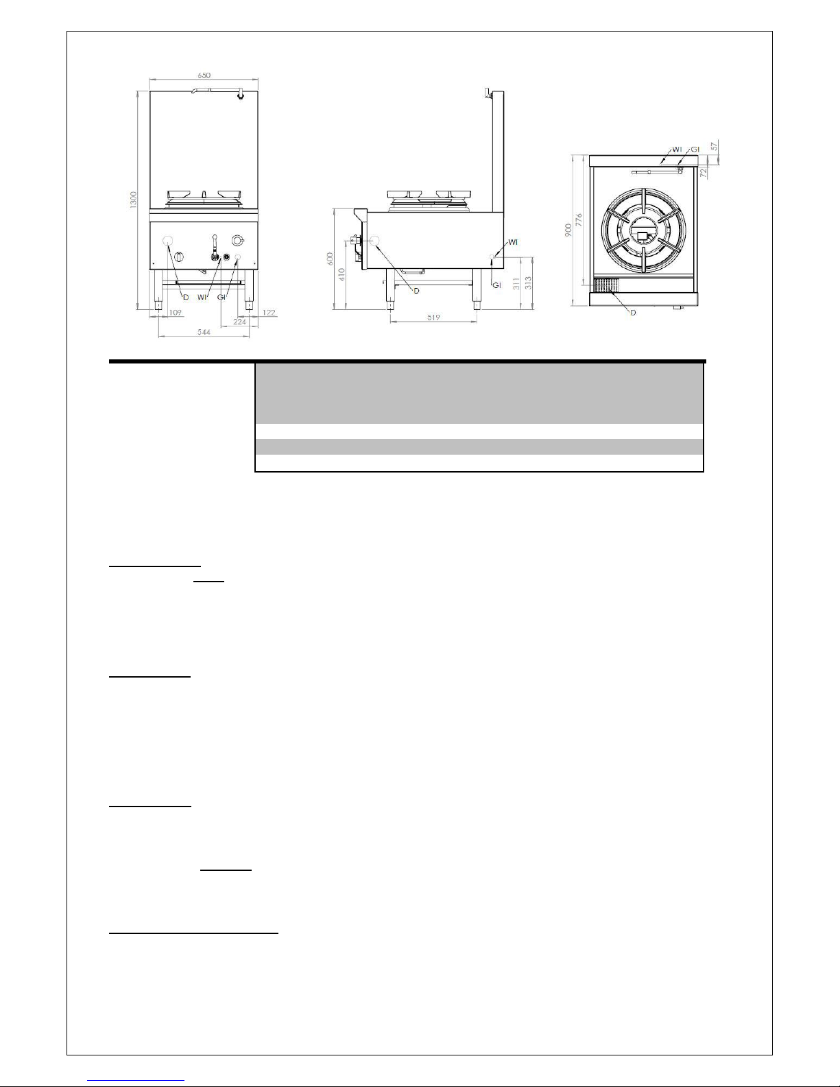
Figure 1: Plumbing Connections
Table 3: Plumbing Connections
Water Inlet (WI)
Gas Inlet (GI)
Water Outlet/Waste (D)
Connection Position from Position from Position from
Floor Rear of Appliance LHS/RHS edge
(mm) (mm) of Appliance
(mm)
½” Copper 310 (+/-5) 60 (+/-5) 220 (+/-5)
¾” male BSP 310 (+/-5) 70 (+/-5) 120 (+/-5)
2” BSP 410 (+/-5) 780 (+/-5) 110 (+/-5)
Installation Instructions
Regulations
The appliance must be installed only by authorised persons and in accordance with the manufacturer’s
installation instructions, local gas fitting regulations, municipal building codes, AS 5601 – Gas Installations
and any other health and safety regulations, local authority, gas, electrical any other statutory regulations.
Data Label
The data label is located on the front of the appliance. This appliance is suitable for Natural Gas and LPG.
Please ensure that the gas supply matches the Data Label ensuring that the gas supply is correct for the
appliance being installed and that adequate supply pressure and volume is available – refer to appliance
data plate for Mj/hr consumption, injector sizes of main burners/pilots, etc.
Ventilation
It is strongly recommended that the appliance is installed under an extraction hood. Ventilation must be in
accordance with AS5601 - Gas Installations. In general, the appliance should have adequate ventilation for
complete combustion of gas, proper flueing and to maintain temperature of immediate surroundings within
safe limits. It is strongly recommended that this appliance is installed under an extraction hood.
Combustible Surfaces
Clearances to combustible surfaces must be in accordance with AS/NZS 5601.1 - Gas Installations, clause
5.12.4.5. Install on a flat/level floor. Where the floor is not fire resistant, a fire resistant material shall be put
under the appliance which shall have a fire resistance rating at least equal to that of 10mm millboard. The
material shall extend at least 50mm beyond the edge of the appliance.
Page 7

7
Leave a clearance of at least 200mm between the appliance and any combustible surface.
No combustible materials shall be located within 500mm of the stock pot table.
Gas Connection
The gas connection is male 3/4” BSP and is situated at the rear of the appliance below the main body
frame. The number of gas inlets corresponds to the number of stock pot support rings the appliance is
fitted with. The inlet is to the ¾” elbow located at the rear of the appliance.
This appliance is available in models for fixed installation.
The appliance can be connected with rigid pipe as specified in AS5601. For fixed installation models
we recommend connection with 20mm copper tube and an AGA approved isolating ball valve.
BEFORE CONNECTING NEW PIPE TO THIS APPLIANCE, THE PIPE MUST BE BLOWN OUT
THOROUGHLY TO REMOVE ALL FO REIGN MATERIAL. FOREIGN MATERIAL IN THE BURNER AND
GAS CONTROLS WILL CAUSE IMPROPER AND DANGEROUS OPERATION.
Connect to gas.
Pressure Test Point
All appliances that are dispatched from our factory are tested and adjusted according to the specifications for
the required gas type. The regulator may require adjustment to achieve required gas pressure.
Check the burner pressure at the test point on the regulator. The test point pressure should be adjusted to
1.00 kPa – Natural gas or 2.60 kPa – LPG with the burners operating at maximum.
Water Connection
The water connection is 15mm copper and is situated at the rear of the appliance below the main
body frame. The number of water inlets varies to client’s particular needs. Water isolation valves are fitted
to all water inlets. Ensure water is flushed through before final connection.
Water waste outlet is located on the left hand side of the waste gutter of the appliance (50mm connection).
The water inlets and water drains should be connected with rigid copper pipes. We do not recommend the
usage of plastic/PVC piping for connection of waste outlet.
Before Leaving - Commissioning
Check all connections for gas leaks with soap and water. Do not use a naked flame for detecting leaks.
Ignite the pilot and main burners as prescribed below to ensure correct operation of gas valves, burners and
ignition. When satisfied with the operation of the appliance, please instruct the user on the correct method of
operation. Ensure that this instruction manual is left with owner of the appliance.
Chimney burner
A. Light the appliance by pressing in the flame safe guard (blue) button and while holding it in turn the
pilot burner knob anti-clockwise to “ON”.
B. Light pilot manually.
C. Continue to hold in the flame safe guard button for about 25 to 30 seconds.
D. Observe whether the pilot is alight.
E. If not repeat steps A. to D.
F. If it is alight turn main burner valve anti-clockwise to the “ON” positions
G. Check that burner is properly alight.
Page 8

8
Chimney Burners – Pilot Light Chimney Burner
A. Ensure pilot light head is located no further than 45mm from the injector located opposite the
burner inlet.
In the event the appliance fails to operate correctly, check the following;
1. Data plate to ensure correct gas type and pressure (adjust if necessary)
2. Adjust aeration by adjusting air shutter located at the front of the venture of the main burner.
3. Injector sizes – check against data plate and installation manual
4. View pilot size and adjust if required.
In case appliance fails to operate correctly after all checks have been carried out, pleased contact;
B&S Commercial Kitchens Pty Ltd
57 Plateau Road
Reservoir VIC 3073
Tel.: + 61 3 9469 4754 Fax.: + 61 3 9469 4504 E-mail: [email protected]
Operating Instructions
WARNING
DO NOT spray aerosols in the vicinity of this appliance while it is in operation.
DO NOT store or use flammable liquids or items in the vicinity of this appliance.
Prior to lighting, smell area surrounding the appliance for gas (please note that as
some gas types are heavier than air, we recommended the operator to also smell
the floor around the appliance).
In the event you smell gas: DO NOT light any appliance. DO NOT touch/ operate
any electrical switch or phone in your building. Call local gas supplier immediately
and follow their instructions.
IMPORTANT WARNING!
ALWAYS ENSURE DECK COOLING IS ACTIVATED WHILST MAIN BURNER IS OPERATING (WHERE
FITTED). WHEN MAIN BURNERS NOT IN USE ALWAYS ENSURE WATER DECK COOLING IS TURNED
OFF TO MINIMISE WATER CONSUMPTION/WASTAGE – REFER OPERATION INSTRUCTIONS.
IMPORTANT WARNING!
ENSURE NO OR MINIMAL AMOUNTS OF OIL AND FOODSTUFFS FALL INTO THE BURNER AREA
WHILST COOKING. FAILURE TO DO SO MAY AFFECT THE EFFICIENT AND SAFE OPERATION ON
THE APPLIANCE AND MAY VOID WARRANTY
Lighting Instructions
1. Turn main gas valve to ‘OFF’.
2. Turn pilot valve anti-clockwise to ‘ON’ position.
3. Depress blue button on flame failure control and manually ignite light pilot.
4. When pilot is alight, keep holding down the blue flame failure button for approximately 15
seconds.
5. Observe the pilot flame is established. If pilot flame goes out wait five minutes and repeat
steps 1 to 4.
6. Turn main gas valve to ‘HIGH’ position.
Page 9
9
Shutdown Procedure
1. Turn main gas valve to ‘OFF’.
2. Turn pilot control valve clockwise to turn off.
3. Observe pilot flame is extinguished.
Deck Cooking (Water Spray) – Where Fitted (Water Cooled Models)
Deck cooling must be activated whenever the main stock pot burners are in use to prevent the deck of
the appliance from buckling and distorting. To activate;.
1. Locate spindle on front panel with ‘Deck’ sticker located above it.
2. Turn spindle anti-clockwise to activate water spray deck cooling. Ensure water pressure is
regulated (by turning spindle clockwise/anti-clockwise) so that only a thin layer of water remains
on the deck and trickles into the waste gutter.
3. When main burner/s is not in use ensure water is turned off by turning spindle clockwise.
Telescopic Laundry Arm – Manual Control (Water Cooled Models)
The telescopic laundry arm serves the purpose for cleaning the appliance and for filling the stock pot
cooking vessel with water to be used for cooking purposes. To activate;
1. Locate spindle on front panel with ‘Spout’ sticker located above it.
2. Turn spindle anti-clockwise to activate water from laundry arm.
3. To cease water flowing from laundry arm, turn ‘Spout’ spindle clockwise.
IMPORTANT WARNING!
NEVER LEAVE WATER RUNNING FROM TELESCOPIC LAUNDRY ARM WHILST POSITIONED
OVER THE STOCK POT SUPPORT RING WITH NO POT/PAN POSITIONED ON IT. ALWAYS MOVE
TELESCOPIC LAUNDRY ARM PARALLEL TO THE SPLASHBACK OG THE APPLIANCE WHENNOT
IN USE. DIRECT FLAME CONTACT WITH LAUNDRY ARM MAY DAMAGE OPERATION OF
LAUNDRY ARM SPOUT.
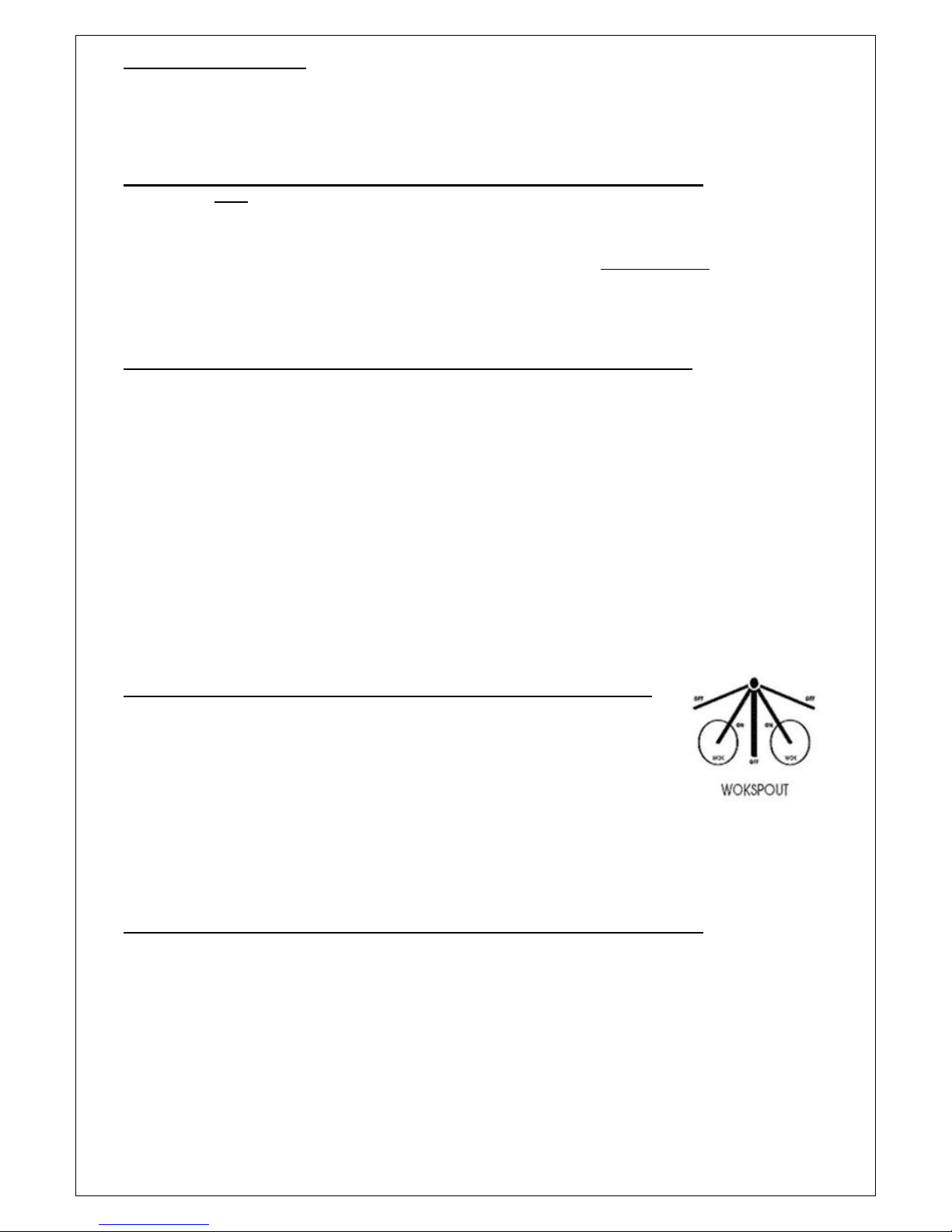
Waterset Automatic Laundry Arm (WokSpout) – Where Fitted
The WokSpout automatically shuts off the water flow when it I moved away from
the stock pot itself (as illustrated to below). It is recommended that the WokSpout
is kept parallel to the splashback of the appliance when not in use. The WokSpout
arm serves the purpose for filling the stock pot cooking pan with water to be used
for cooking purposes.
To activate, move the spout over the stock pot as required.
To stop water flow, move spout back to a position that is either parallel or 90
o
to the splashback of the appliance.
NEVER LEAVE WOKSPOUT IN OFF POSITION LOCATED BETWEEN THE TWO WOK RINGS WHILST
THE MAIN BURNERS ARE IN OPERATION.
Telescopic Laundry Arm Operation with Knee Valve – Where Fitted
The Laundry arm also serves the purpose of cleaning the appliance and/or for filling a stock pot vessel with
water to be used for cooking purposes.
Flow cycle is actuated by deflection and release of the flow lever in any direction from the rest position. The
adjustable flow rate automatically turns off with a non-concussive action after approximately 15 seconds.
Closing time is not adjustable.
Page 10

10
IMPORTANT WARNING!
IN THE EVENT OF FAILURE OF THE WOKSPOUT, WATER FLOW CAN BE CONTROLLED MANUALLY
BY USING THE SPINDLE LOCATED ON FRONT PANEL (WHERE FITTED). WHERE NO SPINDLE
FITTED, WATER SHOULD BE SWITCHED OFF FROM THE ISOLATION VALVE (WHICH IS
RECOMMENDED TO BE FITTED WHEN ISTALLED) AND CONTACT AUTHORISED/ LICENSED
SERVICE PERSONNEL.
Maintenance and Care
To ensure longevity and continued performance efficiency of you appliance, a good cleaning and
maintenance program is paramount. In general the use of steel wool abrasive cloths/cleaners/powders
should not be used to clean this appliance.
Daily Checks & Service
Look for any foreign materials in burner area, leaks, damaged knobs and any other signs that the
stock pot table is not ready and safe for operation. Inspect burner area and ensure pilots are in
position near the burner, and that the pilot flame when ignited is blue in color and approximately 2040mm in length. If fitted with thermocouple ensure pilot flame is in contact with it. Call the
manufacturer if you see any problems. Always ensure that area surrounding pilot and thermocouple
is clear of any fats, oils or foodstuffs.
Clean the exterior surfaces of the stock pot with a clean, damp cloth soaked with mild detergent to
remove any food stuffs, oils, dust and any other materials.
Ensure the primary water drain (located in gutter) is cleared of any food stuffs during operation of
the appliance and on completion of use of the appliance.
The spillage trays located under the main body of the appliance should be removed (by pulling out)
and any carbonised foodstuffs and oils should be removed using a clean, damp cloth soaked in a
mild detergent.
Fortnightly checks & Service
Clean Stock Pot Table Burners
TO BE CARRIED OUT IN THE MORNING OR WHEN THE APPLIANCE HAS NOT BEEN IN USE
FOR A PERIOD OF ONE (1) HOUR – ALWAYS USE CAUTION AS BURNER AREA MAY BE HOT.
Yearly Checks & Service
The appliance should be inspected and adjusted periodically by a qualified service person as
part of any kitchen maintenance program.
B&S recommends that this appliance is inspected at least annually by a authorised service
technician as follows:
o Inspect the table inside-out for excessive build-up of any fats, oils and foodstuffs.
o Inspect that the burners and other components (i.e. pilots, thermocouples, etc.) are in good
condition and functioning properly.
o Inspect all gas connections for leaks and ensure all connections are tightened properly.
o Ensure burner manifold pressure is in accordance with that specified on the data plate of the
appliance.
o Inspect all gas connections for leaks and ensure all connections are tightened properly.
In case of difficulties, contact B&S Commecial Kitchens Pty Ltd or their authorised service agent.
Page 11

11
Servicing Instructions
WARNING!
Servicing shall be carried out by autorised personnel only. Failure to do so will void
the B&S warranty and may result in damage to equipment or injury to personnel.
Before commencing any disassembly/ assembly of gas controls, please ensure the
gas supply is turned off (isolated).
FAILURE TO DO SO WILL VOID B&S WARRANTY AND MAY RESULT IN DAMAGE TO EQUIPMENT
OR INJURY TO PERSONNEL.
Abnormal Operation
Any of the following are considered to be abnormal operation and may require servicing;
Incomplete ignition of burner/burner failing to keep alight.
o Check burner is not blocked.
Yellow tipping of the burner flame.
o Check aeration of burner.
Gas valves which are difficult to turn.
Burner failing to keep alight.
Gaining Access to Gas and/or Water System
To gain access to gas system/components;
1. Undo nut (by turning anti-clockwise) located on the front of the flame failure valve (blue button).
2. Remove knob off pilot valve by gently pulling forward.
3. Remove nut located centrally on the main gas valve (red handle).
4. Remove knee valve wand by unscrewing from main body of knee valve (where fitted).
5. Where deck cooling is fitted remove water spindle control by;
a. Unscrewing cold button on spindle.
b. Gently remove dome handle by gently pulling forward.
c. Unscrew flange by turning anti-clockwise.
d. Unscrew water spindle by turning anti-clockwise (ensure spindle washer is removed).
6. Remove screws located on bottom corners of front panel. Ensure any screws located on the inside
of the gutter panel are also removed.
7. Gently pull front panel outwards from the bottom and lift front panel upwards.
8. REASSEMBLE IN REVERSE ORDER.
Removal of Burner for Service
Follow procedure described under GAINING ACCESS TO GAS AND/OR WATER SYSTEM;
1. Undo barrel union located at in the centre of the gas manifold.
2. Remove burner support screw by undoing wing-nut located on the bottom front of the appliance
frame.
3. Gently lift burner upwards slightly and pull burner outwards.
4. REASSEMBLE IN REVERSE ORDER.
Pilot and Flame Safeguard
Access to pilot assembly is gained by removing the wing-nut located to the left of the pilot assembly which
secures it to the burner support bar, and gently pull forward to gain greater access (refer picture).
1. To service/remove the thermocouple;
a. Undo the nut located underneath and above the thermocouple at the pilot assembly and
gently pull thermocouple downwards.
b. Remove thermocouple from flame failure valve by unscrewing.
c. Reassemble in reverse order.
2. To service/remove pilot burner;
a. Undo nut located underneath the pilot burner on the pilot assembly.
b. Gently pull down pilot flexible gas tube.
Page 12

12
c. Remove injector from pilot and clean (if required).
d. Reassemble in reverse order.
3. REASSEMBLE IN REVERSE ORDER.
Adjustments
Pilot
1. Remove front panel as described under GAINING ACCESS TO GAS CONTROL.
2. To increase gas pressure to pilot, turn adjustment screw located at the top right hand side of the
flame failure devise anti-clockwise.
3. To decrease gas pressure to pilot, turn adjustment screw located at the top right hand side of the
flame failure devise clockwise.
4. REASSEMBLE IN REVERSE ORDER ENSURING POSITION OF PILOT IS AS FOLLOWS;
Ensure pilot light head is light head is located no further than 45mm from the injector located
opposite the burner inlet.
Servicing WokSpout – Where Fitted
The WokSpout TM has a few wearing parts and these comprise a single flow control O-ring in the tap body
and two sealing O-rings on the swivel spout. Whilst it is expected that servicing would only be required at
approximately 200,000 cycles, it recommended that a preventative service be carried out every two years.
Please contact manufacturer for service kit.
Servicing Knee Valve – Where Fitted
The knee valve incorporates a cartridge design for ease of service.
1. Follow procedure described under GAINING ACCESS TO GAS AND/OR WATER SYSTEM
2. To gain access to knee valve cartridge undo knee valve where the deflector meets the cartridge
area.
3. REASSAMBLE IN REVERSE ORDER.
Gas Type Conversion
The following parts componentry require changing the appliance from NG to LPG (vice-versa);
1. Regulator.
2. Burner.
3. Pilot.
In case of any failure in the functioning of the knee valve, unscrew the head assembly and clean the
mechanism under running water. Only use liquid cleaning products. All cleaning products containing
dry powder or powder in suspension are not to be used!
A specific devise is integrated in the cartridge unit to adjust the flow rate. To adjust the flow rate;
1. Undo head assembly
2. Pull off flow adjustor
3. On the exposed end of the housing there are 4 cut-outs for alternative flow rates.
4. Select one for increased/reduced flow.
5. Replace flow adjustor with window over selected cut-out.
6. Screw head assembly into the tap body and tighten fully.
Page 13

13
Table 4: Spare Parts List
Part Number
Description
001NG
Chimney Burner (Natural Gas)
001LP
Chimney Burner (LP/Propane Gas)
005
¾” M&F Ball Va lve
005A
Red Handl e for Ball Valve
006
¾” D3 Safety Valve (Blue Button)
007
Pilot Gas Cock
008
Pilot Gas Cock Knob
011NG
Round Pilot (Natural Gas)
011LP
Round Pilot (Propane Gas)
013
Threaded Thermocouple
800
750mm Sleeved Thermocouple (Front row burner boiling top section – flame failure device)
665NG
¾” Oara Regulator (Natural Gas)
665LP
¾” Oara Regulator (Propane Gas)
020
Telescopic Laundry Arm
503
Pilot Shield
504A
12" Flexi Tube (From Flame Failure Device to Pilot Gas Cock)
504B
18" Flexi Tube (From Pilot Gas Cock to Light Burner)
W001
Knee Valve
W004
Cartridge
W002
Waterset Laundry Arm
W003
Lever Handle
W005
Retaining Disk and Handle
WSPK1
4 x Red Siliscone Rubber, 2 x Black NBR Rubber, 1 x Allen Key, 1 x Page Instruction
WSPK2
Same as WSPK1 Kit plus 45 degree Teflon Coated Brass DR Cap
Page 14

14
Table 5: Troubleshooting
FAULT
POSSIBLE CAUSE
CHECKS
Pilot light not igniting
Blockage of pilot
Adjustment of pressure from flame
control
Check pilot injector is not blocked
as described in servicing
instructions - pilot and flame
safeguard
Check gas pressure to pilot as
described under servicing
instruction - adjustments
Pilot light not establishing
Positioning of thermocouple
Faulty thermocouple
Faulty flame failure control valve
Check connection of the
thermocouple to the control is not
loose
Adjust positioning of thermocouple
to ensure pilot flame is hitting
thermocouple
Contact manufacturer or
authorised service agent
Contact manufacturer or
authorised service agent
Pilot established, main burner not
lighting
Faulty thermocouple
Faulty flame failure control valve
Contact manufacturer
Contact manufacturer
Telescopic laundry arm constantly
running (on water/deck cooled
stock pot table)
Warn tap washer
Change washers in tap assembly
Contact manufacturer or
authorised service agent
Wokspout constantly running
water when in 'OFF' position
Faulty 'O' ring in Wokspout
Changing of 'O' ring as per service
kit and instructions provided with
appliance
Contact manufacturer or
authorised service agent
Short/long laundry arm constantly
running (when fitted with timer
operated knee valve)
Faulty knee valve
Faulty knee valve cartridge
Changing of knee valve cartridge
Contact manufacturer or
authorised service agent
To obtain further service information concerning this appliance, pleased contact;
B&S Commercial Kitchens Pty Ltd
57 Plateau Road
Reservoir VIC 3073
Tel.: + 61 3 9469 4754 Fax.: + 61 3 9469 4504 E-mail: [email protected]
 Loading...