

Page 1
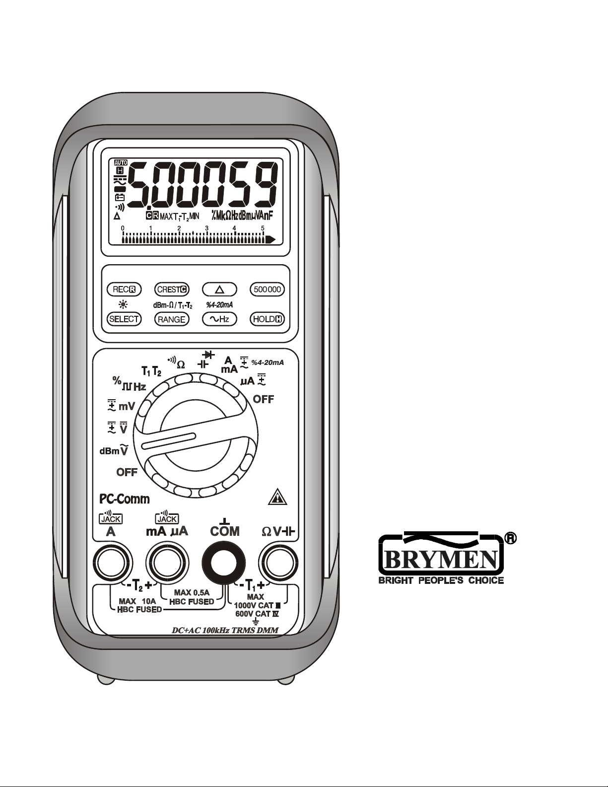
USER'S
MANUAL
BM857s
BM859s
Page 2

1
1) SAFETY
This manual contains information and warnings that must be followed for operating the
meter safely and maintaining the meter in a safe operating condition. If the meter is
used in a manner not specified by the manufacturer, the protection provided by the
meter may be impaired.
Observe proper safety precautions when working with voltages above 30 Vrms, 42.4
Vpeak or 60 VDC. These voltage levels pose a potential shock hazard to the user. Do
not expose this product to rain or moisture. The meter is intended only for indoor use.
Keep your hands/fingers behind the hand/finger barriers (of the meter and the test
probe assembly, where applicable) that indicate the limits of safe access of the
hand-held parts during measurements. Inspect lead wires, connectors, and probes for
damaged insulation or exposed metal periodically. If any defects are found, replace
them immediately. Only use the test probe assembly provided with the meter or a UL
Listed test probe assembly to the same meter ratings or better.
Optional offer premium test probe assembly using silicone lead wire insulation, at
agent’s discretion, is equipped with white inner insulation layers as wear indicators.
Replace them immediately if any of the white layers has become visible.
Disconnect the test leads from the test points before changing functions.
The meter meets IEC/EN/BSEN/CSA_C22.2_No./UL standards of 61010-1 Ed. 3.0,
61010-2-033 Ed. 1.0, 61010-2-033 Ed. 1.0 to Measurement Categories CAT III 1000V
and CAT IV 600V ac & dc.
The accompanied test probe assembly meets IEC/EN/BSEN/CSA_C22.2_No./UL
standards of 61010-031 Ed. 2.0 to the same meter ratings or better. The 61010-031
requires exposed conductive test probe tips to be ≤ 4mm for CAT III & CAT IV ratings.
Refer to the category markings on your probe assemblies as well as on the add-on
accessories (like detachable Caps or Alligator Clips), if any, for applicable rating
changes.
Page 3

2
INTERNATIONAL SYMBOLS
Marking of Electrical and Electronic Equipment (EEE). Do not dispose of this
product as unsorted municipal waste. Contact a qualified recycler
Refer to the explanation in this Manual
Possibility of electric shock
Earth (Ground)
Meter protected throughout by Double Insulation or Reinforced insulation
Fuse
Direct Current (DC)
Alternating Current (AC)
3 Three-phase Alternating Current
Application around and removal from hazardous live conductors is permitted
BRIEF INFORMATION ON MEASUREMENT CATEGORIES
Measurement Category IV is applicable to test and measuring circuits connected at
the source of the building’s low-voltage MAINS installation. Examples are
measurements on devices installed before the main fuse or circuit breaker in the
building installation.
Measurement Category III is applicable to test and measuring circuits connected to
the distribution part of the building’s low-voltage MAINS installation. Examples are
measurements on distribution boards (including secondary meters), circuit-breakers,
cables, bus-bars, junction boxes, switches, socket-outlets, stationary motors in the
fixed installation, and equipment for industrial use.
Measurement Category II is applicable to test and measuring circuits connected
directly to utilization points (socket outlets and similar points) of the low-voltage MAINS
installation. Examples are measurements on MAINS CIRCUITS of household
appliances, portable tools and similar equipment.
2) EUROPEAN DIRECTIVES AND UK STATUTORY REQUIREMENTS
The instruments conform to EUROPEAN (CE) Low-Voltage Directive 2014/35/EU,
Electromagnetic Compatibility Directive 2014/30/EU, and RoHS 2 Directive 2011/65/EU
plus amendment Directive (EU) 2015/863. The instruments also conform to the UK
(UKCA) Electrical Equipment (Safety) Regulations 2016, Electromagnetic Compatibility
Regulations 2016, and The Restriction of the Use of Certain Hazardous Substances in
Electrical and Electronic Equipment Regulations 2012.
Page 4
3
3) PRODUCT DESCRIPTION
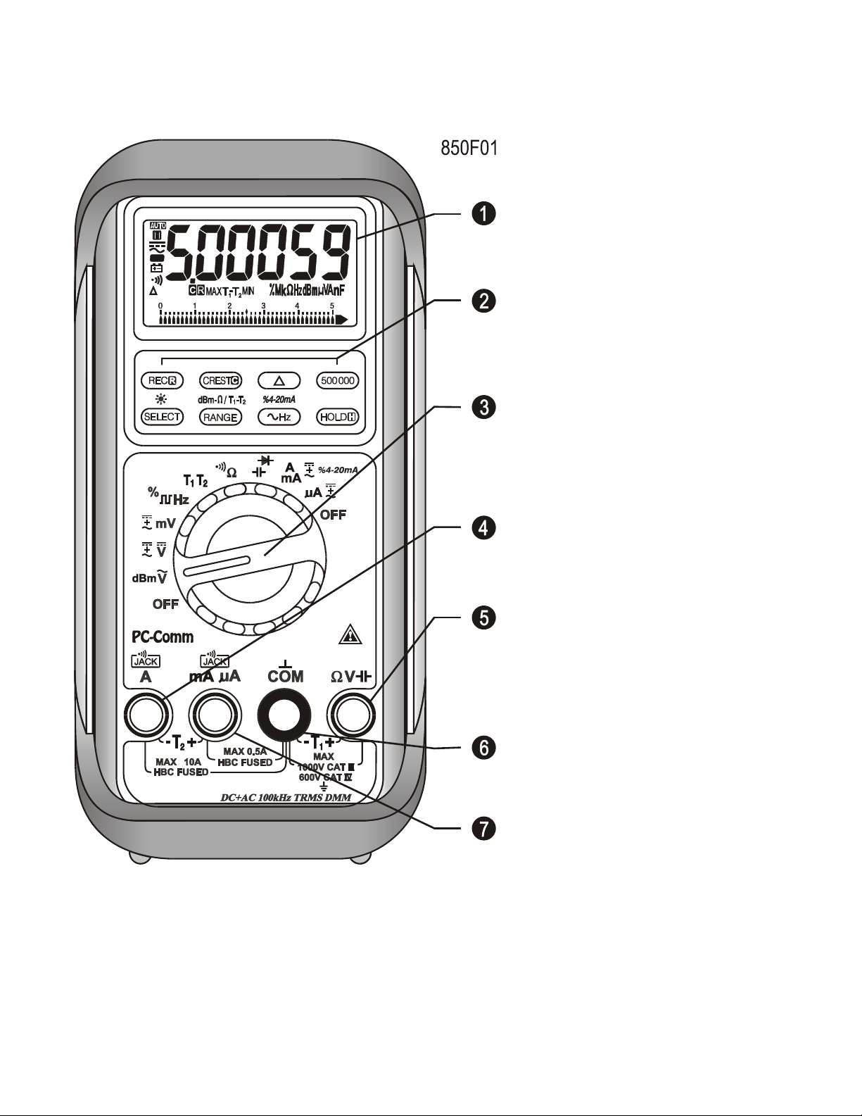
Panel Illustration
1) 5-4/5 digits 500000
counts LCD display
2) Push-buttons for special
functions & features
3) Selector to turn the
Power On or Off and
Select a function
4) Input Jack for 10A (+)
(20A for 30sec) current,
and for T2 (-) function
5) Input Jack (+) for all
functions EXCEPT current
4) OPERATION
(A, mA, A) and T2
functions
6) Common (Ground
reference) Input Jack (-)
for all functions EXCEPT
T2 function
7) Input Jack (+) for
milli-amp, micro-amp, and
T2 (+) functions
NOTE
Before and after hazardous voltage measurements, test the voltage function on a
known source such as line voltage to determine proper meter functioning.
Page 5
4
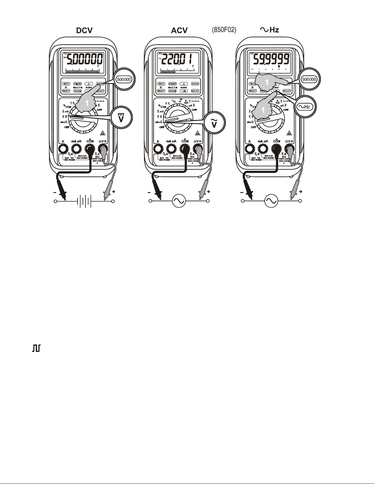
AC Voltage, DC Voltage, DC+AC Voltage, & Hz Line Level Frequency
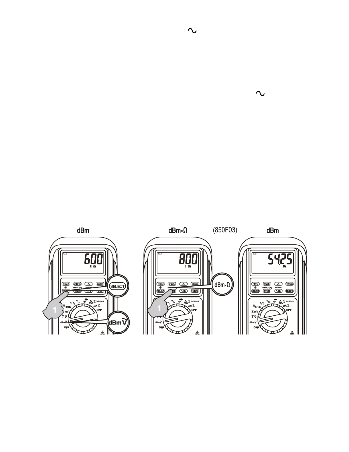
In AC Voltage, press SELECT button momentarily to toggle between AC and dBm. In
DC Voltage, press SELECT button momentarily to toggle between DC, and DC+AC. In
mV Voltage, press SELECT button momentarily to select DC, AC, or DC+AC. The new
settings will be saved automatically to the non-volatile memory as power up default. In
DCV and DCmV, press 500000 button momentarily to toggle between 4-4/5 digits and
5-4/5 digits readings. In voltage or current functions, press the Hz push button
momentarily to activate or to exit Line Level Frequency measuring function. Line Level
Frequency measuring function is designed especially for noisy electrical high voltage
signals.
Note: In dBm function, power up default reference impedance will be displayed for 1
second before displaying the dBm readings. Press dBm- (RANGE) button
momentary to select different reference impedance of 4, 8, 16, 32, 50, 75, 93, 110,
125, 135, 150, 200, 250, 300, 500, 600, 800, 900, 1000, up to 1200. The new
impedance value will be saved automatically to the non-volatile memory as power up
default.
Page 6
5
Note: Line Level Frequency measuring function input sensitivity varies automatically
with voltage (or current) function range selected. The lower the measuring range the
higher the sensitivity. That is, mV function has the highest and the 1000V range has
the lowest as in voltage function ranges. It is recommended to first measure the signal
voltage (or current) level then activate the Hz function in that voltage (or current) range
to automatically get the most appropriate trigger level. When activated from voltage
function, you can also press the RANGE button momentarily to select another trigger
level range manually. The analog bargraph pointer will point at the selected trigger
level range scale 1, 2, 3, or 4. If the Hz reading is unstable, select lower sensitivity to
avoid electrical noise. If the reading shows zero, select higher sensitivity.
Hz Logic Level Frequency and % Duty Cycle functions
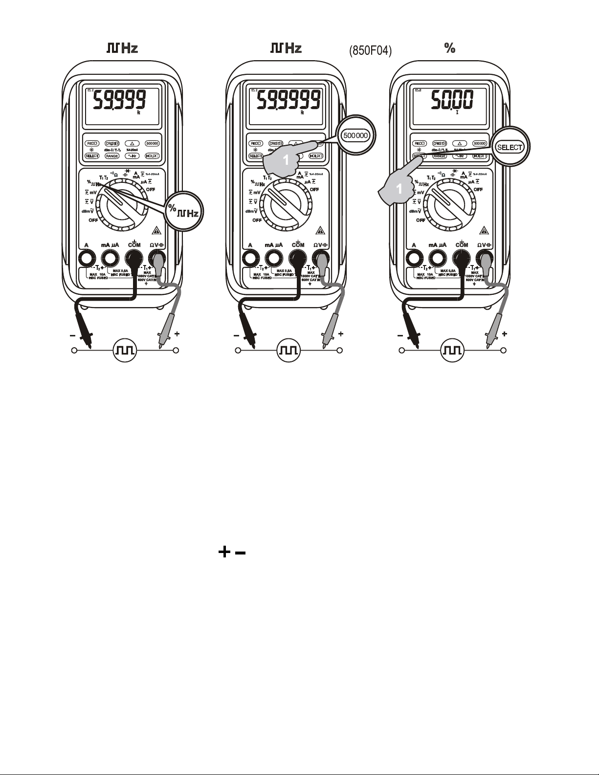
Press SELECT button momentarily to toggle between Hz and % (duty cycle) readings.
The new setting will be saved automatically to the non-volatile memory as power up
default. Press 500000 button momentarily to toggle between 5 full digits and 6 full digits
Hz readings.
Page 7
6
Note: Unlike the Line Level Frequency measuring function as previously stated, this
Logic Level Frequency function is set only at the highest input sensitivity for measuring
digital type electronic signals.
T1-T2 Dual Channels Temperature function (Model 859s only)
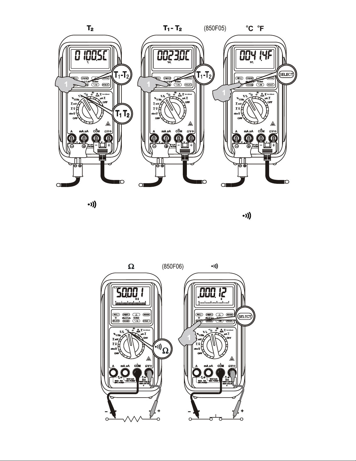
Press SELECT button momentarily to toggle between C and F readings, and the
new setting will be saved automatically in the non-volatile memory as power up default.
Press T1-T2 (RANGE) button momentarily to select T1, T2, or T1-T2 readings.
Note: Insert the banana plug K-type temperature bead probe Bkp60 (standard
accessory x 1) with correct polarities. Dual channels T1-T2 readings require 2
probes. You can also use a plug adapter Bkb32 (Optional purchase) with banana pins
to K-type socket to adapt other standard K type mini plug temperature probes.
Page 8
7
Resistance, Continuity functions
Press SELECT button momentarily to toggle between and Continuity functions.
The new setting will be saved automatically to the non-volatile memory as power up
default. Continuity function is convenient for checking wiring connections and operation
of switches. A continuous beep tone indicates a complete wire.
Page 9
8
NOTE
Using resistance or continuity function in a live circuit will produce false results and
may damage the meter. In many cases the suspected component must be
disconnected from the circuit to obtain an accurate reading.
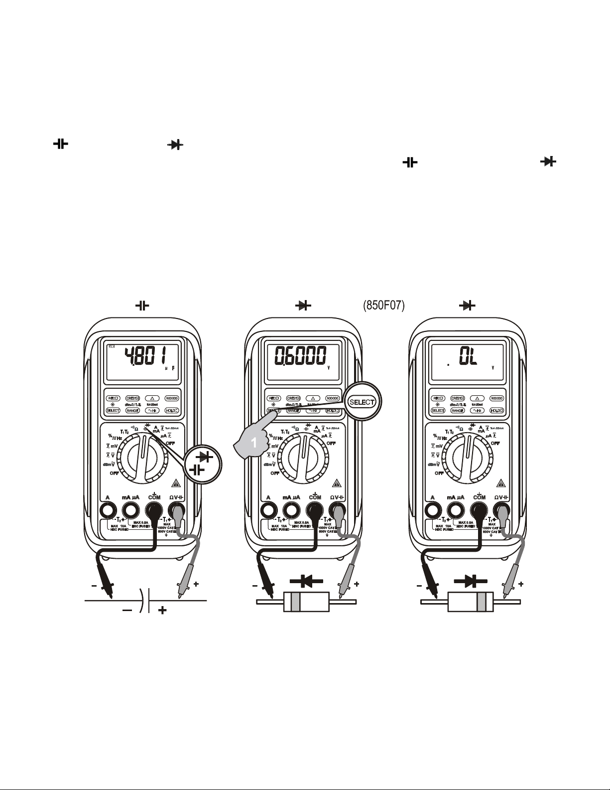
Capacitance,
Diode test function
Press SELECT button momentarily to toggle between Capacitance and
Diode test functions. The new setting will be saved automatically to the non-volatile
memory as power up default.
NOTE
Discharge capacitors before making any measurement. Large value capacitors should
be discharged through an appropriate resistance load.
Note: Normal forward voltage drop (forward biased) for a good silicon diode is between
0.400V to 0.900V. A reading higher than that indicates a leaky diode (defective). A zero
reading indicates a shorted diode (defective). An OL indicates an open diode
(defective). Reverse the test leads connections (reverse biased) across the diode. The
digital display shows OL if the diode is good. Any other readings indicate the diode is
resistive or shorted (defective).
Page 10
9
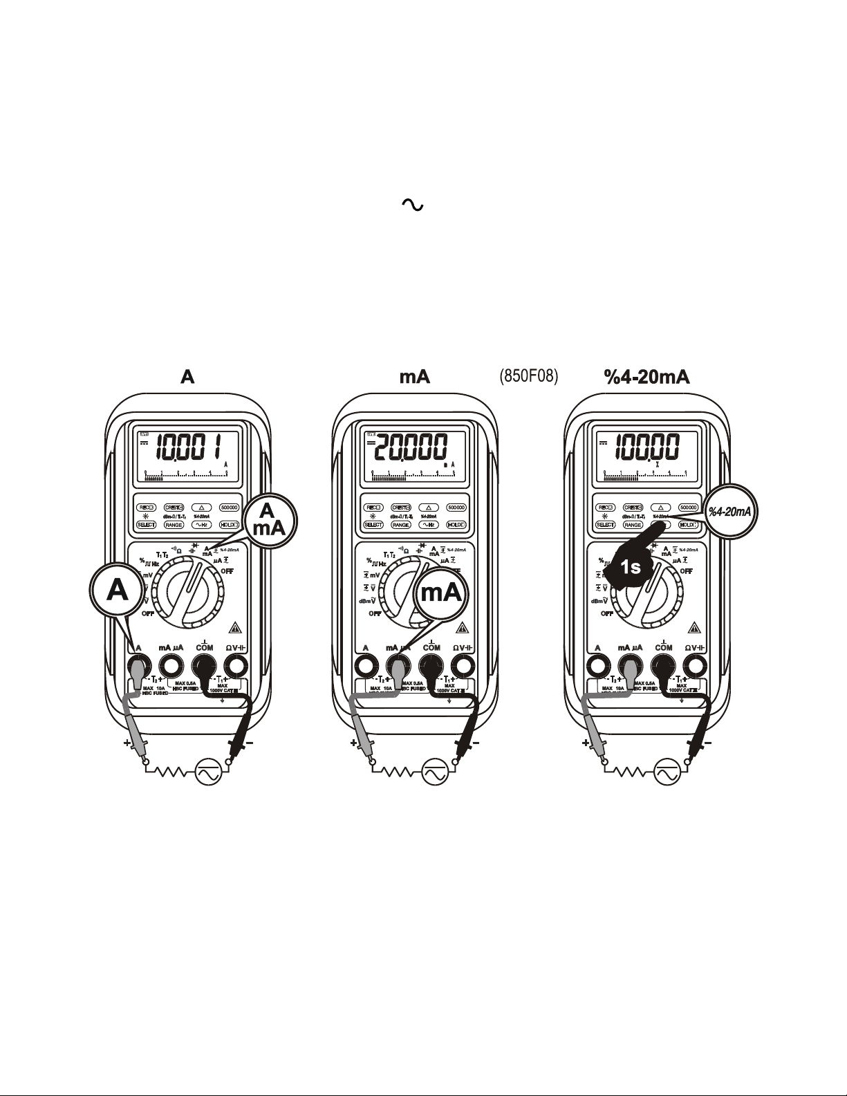
A, mA, A, and %4-20mA Current functions
Insert the red test lead into the correct A/mA or A input jack. Press SELECT button
momentarily to select DC, AC, or DC+AC. The new settings will be saved automatically
to the non-volatile memory as power up default. In DC mA function, neither in AC nor in
DC+AC, press and hold the %4-20mA ( Hz) button for 1 second or more to display
the current digital data in terms of loop current percentage (%) value. It is set at 4mA =
0% (zero) and 20mA = 100% (span) with 0.01% high resolution, which virtually extends
the meters’ capability to test and regulate the externally powered loop current in the
industrial process control applications. The analog bar-graph remains showing the mA
current value to alert the user.
NOTE: When measuring a 3-phase system, special attention should be taken to the
phase-to-phase voltage that is significantly higher than the phase-to-earth voltage. To
avoid exceeding the voltage rating of the protection fuse(s) accidentally, always
consider the phase-to-phase voltage as the working voltage for the protection fuse(s).
Page 11

10
PC-COMM computer interface capabilities
The instrument equips with an optical isolated interface port at the meter back for data
communication. Optional purchase PC interface kit BRUA-85Xa (BC-85Xa RS232C
optical adapter cable + BS85X software CD + BUA-2303 USB-to-Serial adaptor) is
required to connect the meter to the PC computer. The Bs85x Data Recording System
software equips with a digital meter, an analog meter, a comparator meter, and a Data
Graphical recorder display. Refer to the README file in the interface kit for further
details.
MAX/MIN RECORDING mode
Press REC button momentarily to activate MAX/MIN recording mode. The LCD
annunciators “R” and “MAX MIN” turn on. The meter beeps when new maximum or
minimum reading is updated. Press the button momentarily to read throughout the
Maximum (MAX), Minimum (MIN), and Maximum minus Minimum (MAX-MIN) readings.
Press the button for 1 second or more to exit MAX/MIN recording mode. Auto Power
Off feature will be disabled automatically in this mode.
CREST Capture (Instantaneous Peak Hold) mode
Press CREST button momentarily to activate CREST mode to capture voltage or
current signal duration as short as 0.8ms. This mode is available in DC, AC, DC+AC
modes of voltage and current functions. The LCD annunciators “C” & “MAX” turn on.
The meter beeps when new maximum or minimum reading is updated. Press the
button momentarily to read throughout the Maximum (MAX), Minimum (MIN), and
Maximum minus Minimum (MAX-MIN) readings. Press the button for 1 second or more
to exit CREST capture mode. Auto Power Off feature will be disabled automatically in
this mode.
Relative Zero mode
Relative Zero allows the user to offset the meter consecutive measurements with the
displaying reading as the reference value. Practically MAX/MIN recording feature
readings can also be set as relative reference value. Press the button momentarily
to activate and to exit Relative Zero mode.
500000 high resolution stable mode
In DC voltage and frequency functions, press the 500000 button momentarily to toggle
between the 4-4/5 digits fast mode and the 5-4/5 digits high resolution stable mode.
Backlighted display
Page 12

11
Press the SELECT button for 1 second or more to turn on or off the display backlight
function. It will also be turned off automatically after 30 seconds to extend battery life.
Manual or Auto-ranging
Press the RANGE button momentarily to select manual-ranging mode, and the meter
will remain in the range it was in, the LCD annunciator turns off. Press the
button momentarily again to step through the ranges. Press and hold the button for 1
second or more to resume auto-ranging mode.
Note: Manual ranging mode feature is not available in Hz function.
Hold
The hold function freezes the display for later view. Press the HOLD button
momentarily to activate or to exit the hold function.
Set Beeper Off
Press the Hz button while turning the meter on to disable the push button operating
beeper feature. However, the continuity and Jack Beep input warning features remain.
Beep-Jack™ Input Warning
The meter beeps as well as displays “InErr” to warn the user against possible damage
to the meter due to improper connections to the A, mA, or A input jacks when other
function (like voltage function) is selected.
Intelligent Auto Power Off (APO)
The Intelligent Auto Power Off (APO) mode turns the meter off automatically to extend
battery life after approximately 17 minutes of no activities. Activities are specified as: 1)
Rotary switch or push button operations, and 2) Significant measuring readings of
above 10% of range or non-OL readings. In other words, the meter will intelligently
avoid entering the APO mode when it is under normal measurements. To wake up the
meter from APO, press the RECORD button momentarily or turn the rotary switch to
the OFF position and then turn back on again. Always turn the rotary switch to the OFF
position when the meter is not in use.
Disabling Auto Power Off
Press the RANGE button while turning the meter on to disable the Auto Power Off
(APO) feature.
5) MAINTENANCE
NOTE
Page 13

12
To avoid electrical shock, disconnect the meter from any circuit, remove the test
leads from the input jacks and turn OFF the meter before opening the case. Do not
operate with open case. Install only the same type of fuse or equivalent
Calibration
Periodic calibration at intervals of one year is recommended to maintain meter
accuracy. Accuracy is specified for a period of one year after calibration.
If self-diagnostic message “rE-O” is being displayed while powering on, the meter is
re-organizing internal parameters. Do not switch off the meter then, and it will be back
to normal measurement shortly. However, if self-diagnostic message “C_Er” is being
displayed while powering on, some meter ranges might be largely out of specifications.
To avoid mis-leading measurements, stop using the meter and send it for re-calibration.
Refer to the LIMITED WARRANTY section for obtaining warranty or repairing service.
Trouble Shooting
If the instrument fails to operate, check battery, fuses, leads, etc., and replace as
necessary. Double check operating procedure as described in this user’s manual. If the
instrument voltage-resistance input terminal has subjected to high voltage transient
(caused by lightning or switching surge to the system) by accident or abnormal
conditions of operation, the series fusible resistors will be blown off (become high
impedance) like fuses to protect the user and the instrument. Most measuring functions
through this terminal will then be open circuit. The series fusible resistors and the spark
gaps should then be replaced by qualified technician. Refer to the LIMITED
WARRANTY section for obtaining warranty or repairing service.
Cleaning and Storage
Periodically wipe the case with a damp cloth and mild detergent; do not use abrasives
or solvents. If the meter is not to be used for periods of longer than 60 days, remove
the battery and store it separately.
Page 14
13
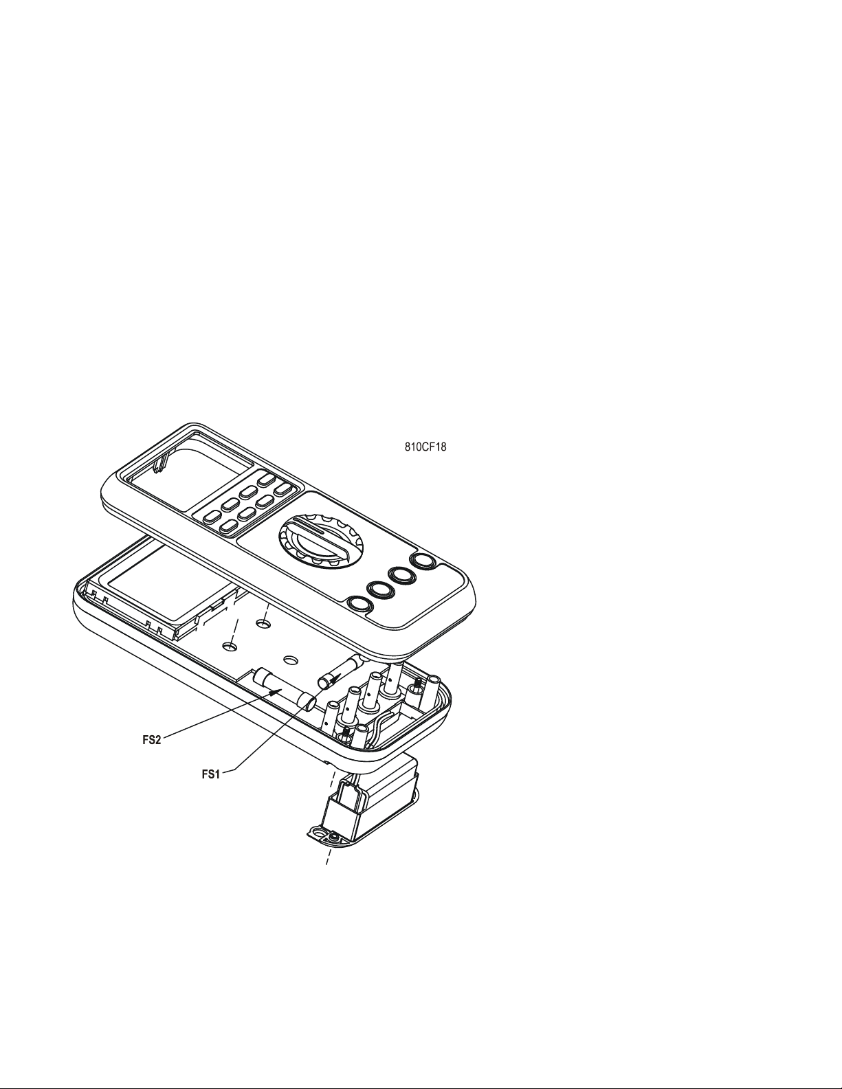
Battery and Fuse replacement
Battery use:
9V alkaline battery NEDA1604A, JIS6AM6 or IEC6LF22
Fuse (FS1) for AmA current input:
0.44A/1000V, IR 10kA or better, F fuse; Dimension: 10 x 38mm
Fuse (FS2) for A current input:
11A/1000V, IR 20kA or better, F fuse; Dimension: 10 x 38mm
Battery replacement for models with battery access door:
Loosen the 2 screws from the battery access door of the case bottom. Lift the battery
access door and thus the battery compartment up. Replace the battery. Re-fasten the
screws.
Fuse replacement (and also
Battery replacement for splash
proof version without battery
access door):
Loosen the 4 screws from the
case bottom. Lift the end of the
case bottom nearest the input
jacks until it unsnaps from the
case top. Replace the blown
fuse(s) and/or the battery.
Replace the case bottom, and
ensure that all the gaskets are
properly seated and the two
snaps on the case top (near the
LCD side) are engaged.
Re-fasten the screws.
Page 15

14
6) SPECIFICATIONS
GENERAL SPECIFICATIONS
Display: 4-4/5 digits 50,000 counts. Selectable stable mode 5-4/5 digits 500,000 counts for
DC Voltage, & 6 digits 999,999 counts for Hz
Polarity: Automatic
Update Rate:
4-4/5 digits fast mode: 5 per second nominal;
5-4/5 digits stable mode: 1.25 per second nominal;
42 Segments Bar graph: 60 per second max
Operating Temperature: 0C to 45C
Relative Humidity: Maximum relative humidity 80% for temperature up to 31C decreasing
linearly to 50% relative humidity at 45C
Pollution degree: 2
Storage Temperature: -20C to 60C, < 80% R.H. (with battery removed)
Altitude: Operating below 2000m
Temperature Coefficient: nominal 0.1 x (specified accuracy)/ C @(0C -- 18C or 28C --
40C), or otherwise specified
Sensing: AC, AC+DC True RMS
Safety: Double insulation per IEC/UL/EN/BSEN 61010-1 Ed. 3.0, IEC/UL/EN/BSEN
61010-2-030 Ed. 1.0, IEC/UL/EN/BSEN 61010-2-033 Ed. 1.0, IEC/UL/EN/BSEN 61010-031
Ed. 2.0 and the corresponding CAN/CSA-C22.2 regulations to Measurement Categories III
1000V AC & DC and Category IV 600V AC & DC
Overload Protections:
A & mA : 0.44A/1000V DC/AC rms, IR 10kA, F fuse
A : 11A/1000V DC/AC rms, IR 20kA, F fuse
V : 1100V DC/AC rms
mV, , & Others : 1000V DC/AC rms
Transient protection: 8kV (1.2/50s surge)
E.M.C.: Meets EN61326-1
In an RF field of 3V/m:
Capacitance function is not specified
Other function ranges: Total Accuracy = Specified Accuracy + 100 digits
Performance above 3V/m is not specified
Power Supply: Single Alkaline 9V battery; NEDA1604A, JIS6AM6 or IEC6LF22
Power Consumption: 6mA typical
Low Battery: Below approx. 7V
APO Timing: Idle for 17 minutes
APO Consumption: 55A typical for Model 857s; 30A typical for Model 859s
Dimension: L186mm X W87mm X H35.5mm; L198mm X W97mm X H55mm with holster
Weight: 390 gm; 500 gm with holster
Page 16

15
Accessories: Test leads (pair), holster, battery installed, user's manual, Bkp60 banana
plug K-type thermocouple x 1 (Model 859s only)
Optional Accessories: BRUA-85Xa PC interface kit (BC-85Xa RS232 optical adapter cable
+ Bs85X software CD + BUA-2303 USB-to-Serial adaptor), Bkb32 banana pins to K-type
socket plug adapter
Special Features: Record MAX, MIN, MAX-MIN readings. Crest (Instantaneous Peak hold)
MAX, MIN, MAX-MIN readings. Relative zero mode. 500,000 counts high resolution stable
reading mode. Backlighted display. dBm readings. T1-T2 differential temperature readings
(Model 859s only). %4-20mA loop current readings. High noise rejection filtered Line Level
Frequency mode. Data Hold. Audible & visible input warning.
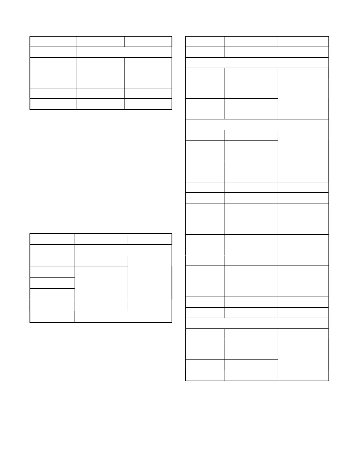
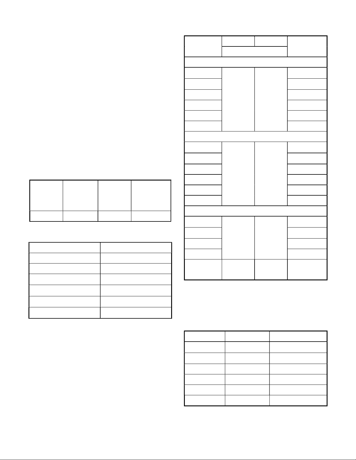
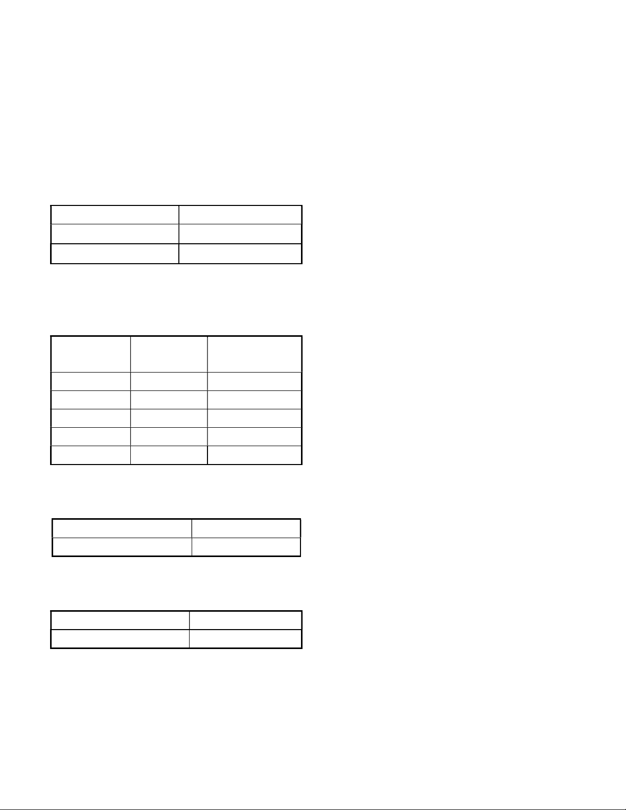
ELECTRICAL SPECIFICATIONS
Accuracy is (% reading digits + number of digits) or otherwise specified, at 23C 5C &
less than 75% relative humidity.
True RMS voltage & current accuracies are specified from 5 % to 100 % of range or
otherwise specified. Maximum Crest Factor < 5:1 at full scale & < 10:1 at half scale, and with
frequency components within the specified frequency bandwidth for non-sinusoidal
waveforms.
Page 17
16
RANGE
859
s 857
s
Accuracy
500.00 mV,
0.02% + 2d
0.03% + 2d
500.00V
0.04%+2d
0.05% + 2d
1000.0V
0.05%+ 2d
0.1%+2d
RANGE
859
s 857s
Accuracy
RANGE
859
s 857
s
Accuracy*
20Hz
--
45Hz
500.00mV,
50.000V
500.00V,
1000.0V
Unspec'd
45Hz
--
300Hz
500.00mV
0.3% + 20d
5.0000V,
50.000V
0.8% + 20d
500.0
0V,
0.4% + 40d
300Hz
--
5kHz
300Hz --
1kHz
500.00mV
0.3% + 10d
0.8%+40d
5.0000V,
1000.0V
0.8% + 40d
(300Hz
--
1kHz)
1.0%+40d
5kHz
--
20kHz
1kHz
--
20kHz
500.00mV
0.5%+20d
1dB**
5.0000V,
50.000V
0.8%+20
d 2dB**
500.00V
0.5%+20d
3dB**
1000.0V
Un
spec'd
Unspec'd
20kHz
--
100kHz
500.00mV
2.5
%+40d
5.0000V,
50.000V
4.0%+40d**
500.00V
Unspec'd
1000.0V
DC Voltage
5.0000V,
AC & AC+DC Voltage
50.000V
NMRR: >60dB @ 50/60Hz
CMRR: >120dB @ DC, 50/60Hz, Rs=1k
Input Impedance: 10M, 30pF nominal
(80pF nominal for 500mV range)
Crest mode (Instantaneous Peak Hold)
Accuracy: Specified accuracy 100 digits
for changes > 0.8ms in duration
Ohms
5.0000V,
1000.0V
50.000V,
500.00V
1.5% + 60d
0.4% + 40d
Unspec'd
0.8%+60d
2.0%+60d
500.00
0.07%+10d
5.0000k
0.1%+6d
50.000k
0.07%+2d
500.00k
5.0000M
50.000M
0.2%+6d 0.4%+6d
2.0%+6d 2.0%+6d
Open Circuit Voltage: < 1.3VDC ( < 3VDC
for 500 range)
Audible Continuity Tester
Audible threshold: between 20 and 200
Response time < 100s
Unspec'd
*From 5% to 10% of range:
accuracy % of reading (or in dB) + 80d
**From 5% to 10% of range:
accuracy % of reading (or in dB) + 180d
**From 10% to 15% of range:
accuracy % of reading (or in dB) + 100d
Page 18
17
Range
Accuracy
Test
Open
5.0000V
1%+1d
0.4mA
< 3.5 VDC
RANGE
Accuracy*
50.00nF
0.8% + 3d
500.0nF
0.8% + 3d
859
s 857
s
Accuracy
50Hz
--
60Hz
50.000mA
3.3mV/mA
500.00mA
3.3mV/mA
5.0000A
45m
V/A
10.000A*
45m
V/A 40Hz
–
1kHz
50.000mA
3.3mV/mA
500.00mA
3.3mV/mA
5.0000A
45m
V/A 10.000A*
45m
V/A 1kHz
–
10kHz
50.000mA
3.3mV/mA
500.00mA
3.3mV/mA
5.0000A
10.000A*
RANGE
Accuracy
Bur
den Voltage
50.000mA
0.15%+
20d
3.3mV/mA
500.00mA
0.1%+
30d
3.3mV/mA
5.0000A
0.5%+
20d
45m
V/A
10.000A*
0.5%+20d
45mV/A
CMRR: >80dB @ DC to 60Hz, Rs=1k
AC & AC+DC Current
Input Impedance: 10M, 30pF nominal
(80pF nominal for 500mV range)
Residual reading less than 50 digits with
test leads shorted.
dBm
At 600, -11.76dBm to 54.25dBm,
Accuracy: 0.25dB + 2d (@40Hz -- 20kHz)
Input Impedance: 10M, 30pF nominal
Selectable reference impedance of 4, 8,
16, 32, 50, 75, 93, 110, 125, 135, 150, 200,
250, 300, 500, 600, 800, 900, 1000, 1200
Diode Tester
Current
(Typical)
Circuit
Voltage
RANGE
500.00A
5000.0A
500.00A
5000.0A
0.5%
+50d
0.7%
+50d
Burden
Voltage
0.15mV/A
0.15mV/A
1.0%
+40d
0.15mV/A
0.15mV/A
1.0%
+40d
Capacitance
5.000F
50.00F
500.0F**
9999F**
1.5% + 3d
2.5% + 3d
3.5% + 5d
5.0% + 5d
*Accuracies with film capacitor or better
**In manual-ranging mode, measurements
not specified below 45.0F and 450F for
500.0F and 9999F ranges respectively
500.00A
5000.0A
2.0%
0.15mV/A
0.15mV/A
Unspec'd
+50d
Unspec'd Unspec'd 45mV/A
*10A continuous, >10A to 20A for 30
second max with 5 minutes cool down
interval
DC Current
500.00A
5000.0A
0.15%+20d
0.1%+20d
0.15mV/A
0.15mV/A
*10A continuous, >10A to 20A for 30
second max with 5 minutes cool down
interval
Page 19
18
RANGE
Accuracy
Function
RANGE
Sensitivity
(Sine RMS)
Range
500
mV 1
00mV
10Hz ~
200
kHz
5V 1V 10Hz ~
200
kHz
50V
10V 10
Hz ~
100
kHz
500V
100V 10
Hz ~
100
kHz
1000V
900V
10Hz ~ 10kHz
RANGE
Accu
r
acy
5.0000Hz
--
2.00000MHz
0.002%+4d
RANGE
Accuracy
0.1%
-- 99.99%
3d/kHz+2d
DC Loop Current %4--20mA
4mA = 0% (zero)
20mA = 100% (span)
Resolution: 0.01%
Accuracy: 25d
T1-T2 Dual Temperature (Model 859s
only)
-50.0C to 1000.0C 0.3%+1C
-58.0F to 1832.0F 0.3%+2F
Thermocouple range & accuracy not
included
Hz Line Level Frequency
Accuracy: 0.02%+4d
Hz Logic Level Frequency
Sensitivity: 2.5Vp square wave
%Duty Cycle
Input Frequency:
5Hz -- 500 kHz, 5V Logic Family
Page 20

LIMITED WARRANTY
BRYMEN warrants to the original product purchaser that each product it manufactures
will be free from defects in material and workmanship under normal use and service
within a period of one year from the date of purchase. BRYMEN's warranty does not
apply to accessories, fuses, fusible resistors, spark gaps, batteries or any product
which, in BRYMEN's opinion, has been misused, altered, neglected, or damaged by
accident or abnormal conditions of operation or handling.
To obtain warranty service, contact your nearest BRYMEN authorized agent or send
the product, with proof of purchase and description of the difficulty, postage and
insurance prepaid, to BRYMEN TECHNOLOGY CORPORATION. BRYMEN assumes
no risk for damage in transit. BRYMEN will, at its option, repair or replace the defective
product free of charge. However, if BRYMEN determines that the failure was caused by
misused, altered, neglected, or damaged by accident or abnormal conditions of
operation or handling, you will be billed for the repair.
THIS WARRANTY IS EXCLUSIVE AND IS IN LIEU OF ALL OTHER WARRANTIES,
EXPRESSED OR IMPLIED, INCLUDING BUT NOT LIMITED TO ANY IMPLIED
WARRANTY OR MERCHANTABILITY OR FITNESS FOR A PARTICULAR PURPOSE
OR USE. BRYMEN WILL NOT BE LIABLE FOR ANY SPECIAL, INDIRECT,
INCIDENTAL OR CONSEQUENTIAL DAMAGES.
BRYMEN TECHNOLOGY CORPORATION
TEL: +886 2 2226 3396
FAX: +886 2 2225 0025
http://www.brymen.com
PRINTED ON RECYCLABLE PAPER, PLEASE RECYCLE
COPYRIGHT © MMXXII Btc, ALL RIGHTS RESERVED
P/N: 7M1C-1271-61010-2-033Ed1 PRINTED IN TAIWAN
 Loading...