

Page 1
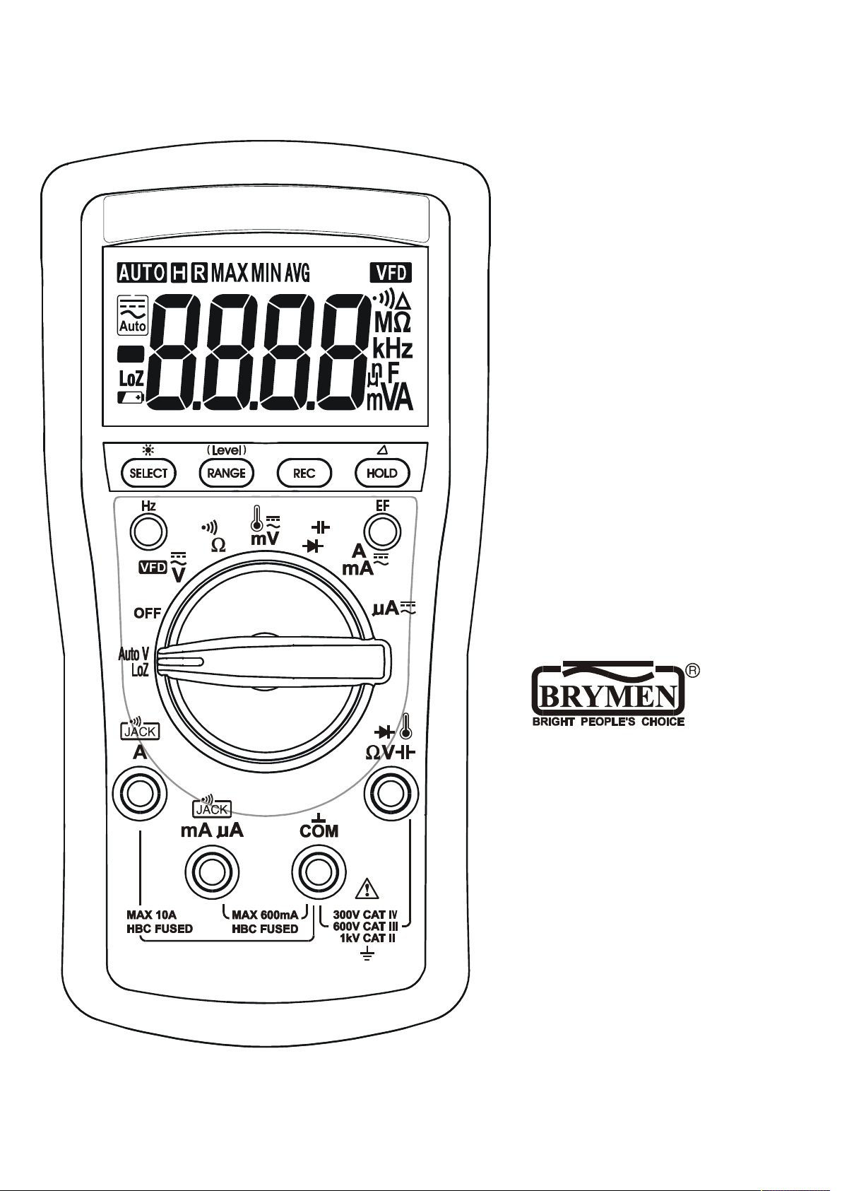
USER'S
MANUAL
BM231
BM233
BM235
Page 2

1
1) SAFETY
This manual contains information and warnings that must be followed for operating the
meter safely and maintaining the meter in a safe operating condition. If the meter is
used in a manner not specified by the manufacturer, the protection provided by the
meter may be impaired.
Terms in this manual
WARNING identifies conditions and actions that could result in serious injury or even
death to the user.
CAUTION identifies conditions and actions that could cause damage or malfunction
in the instrument.
WARNING
To reduce the risk of fire or electric shock, do not expose this product to rain or
moisture. The meter is intended only for indoor use.
Keep your hands/fingers behind the hand/finger barriers (of the meter and the test
probe assembly, where applicable) that indicate the limits of safe access of the handheld parts during measurements. Inspect lead wires, connectors, and probes for
damaged insulation or exposed metal before using the meter. If any defects are found,
replace them immediately. Only use the probe assembly provided with the meter or a
UL Listed Probe Assembly to the same meter ratings or better.
IEC 61010-031 requires exposed conductive test probe tips to be ≤ 4mm for CAT III &
CAT IV ratings. Refer to the category markings on your probe assemblies as well as on
the add-on accessories (like detachable Caps or Alligator Clips), if any, for applicable
rating changes.
Observe proper safety precautions when working with voltages above 33 Vrms, 46.7
Vpeak or 70 VDC. These voltage levels pose a potential shock hazard to the user.
Before and after hazardous voltage measurements, check the voltage function on a
known source such as line voltage to determine proper meter functioning.
CAUTION
Disconnect the test leads from the test points before changing functions.
Page 3

2
International Electrical Symbols
Marking of Electrical and Electronic Equipment (EEE). Do not dispose of this
product as unsorted municipal waste. Contact a qualified recycler
Caution! Refer to the explanation in this Manual
Caution! Possibility of electric shock
Earth (Ground)
Meter protected throughout by Double Insulation or Reinforced insulation
Fuse
Direct Current (DC)
Alternating Current (AC)
3 Three-phase Alternating Current
Brief Information about Measurement Categories
Measurement Category IV is applicable to test and measuring circuits connected at
the source of the building’s low-voltage MAINS installation. Examples are
measurements on devices installed before the main fuse or circuit breaker in the
building installation.
Measurement Category III is applicable to test and measuring circuits connected to
the distribution part of the building’s low-voltage MAINS installation. Examples are
measurements on distribution boards (including secondary meters), circuit-breakers,
wiring, including cables, bus-bars, junction boxes, switches, socket-outlets in the fixed
installation, and equipment for industrial use and some other equipment such as
stationary motors with permanent connection to the fixed installation.
Measurement Category II is applicable to test and measuring circuits connected
directly to utilization points (socket outlets and similar points) of the low-voltage MAINS
installation. Examples are measurements on MAINS CIRCUITS of household
appliances, portable tools and similar equipment.
2) CENELEC DIRECTIVES
The instruments conform to CENELEC Low-voltage directive 2006/95/EC,
Electromagnetic compatibility directive 2004/108/EC and RoHS directive 2011/65/EU.
Page 4
3
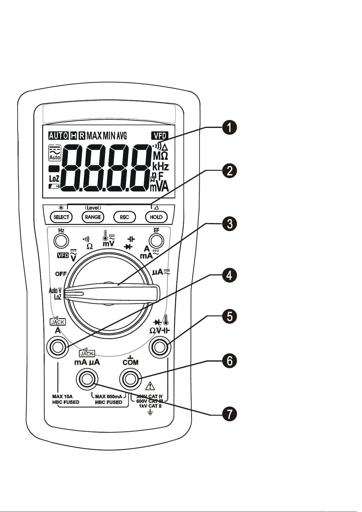
3) PRODUCT DESCRIPTION
Note: Top of the line model is used as representative for illustration purposes. Please
refer to your respective model for function availability.
1) 3-5/6 digits 6000
counts LCD display
2) Push-buttons for
special functions &
features
3) Selector to turn the
Power On or Off and
Select a function
4) Input Jack for 10A
(20A for 30sec) current
function
5) Input Jack for all
functions EXCEPT A,
mA & A current
functions
6) Common (Ground
reference) Input Jack for
all functions
7) Input Jack for A and
mA current function
Page 5

4
True RMS
RMS (Root-Mean-Square) is a term used to describe the effective or equivalent DC
value of an AC signal. True RMS is the term which identifies a DMM that responds
accurately to the effective RMS value regardless of the waveforms such as: square,
sawtooth, triangle, pulse trains, spikes, as well as distorted waveforms with the
presence of harmonics. Harmonics may cause :
1) Overheated transformers, generators and motors to burn out faster than normal
2) Circuit breakers to trip prematurely
3) Fuses to blow
4) Neutrals to overheat due to the triplen harmonics present on the neutral
5) Bus bars and electrical panels to vibrate
Crest Factor
Crest Factor is the ratio of the Crest (instantaneous peak) value to the True RMS
value, and is commonly used to define the dynamic range of a True RMS DMM. A pure
sinusoidal waveform has a Crest Factor of 1.414. A badly distorted sinusoidal
waveform normally has a much higher Crest Factor.
4) OPERATION
CAUTION
Before and after hazardous voltage measurements, test the voltage function on a
known source such as line voltage to determine proper meter functioning.
Page 6
5
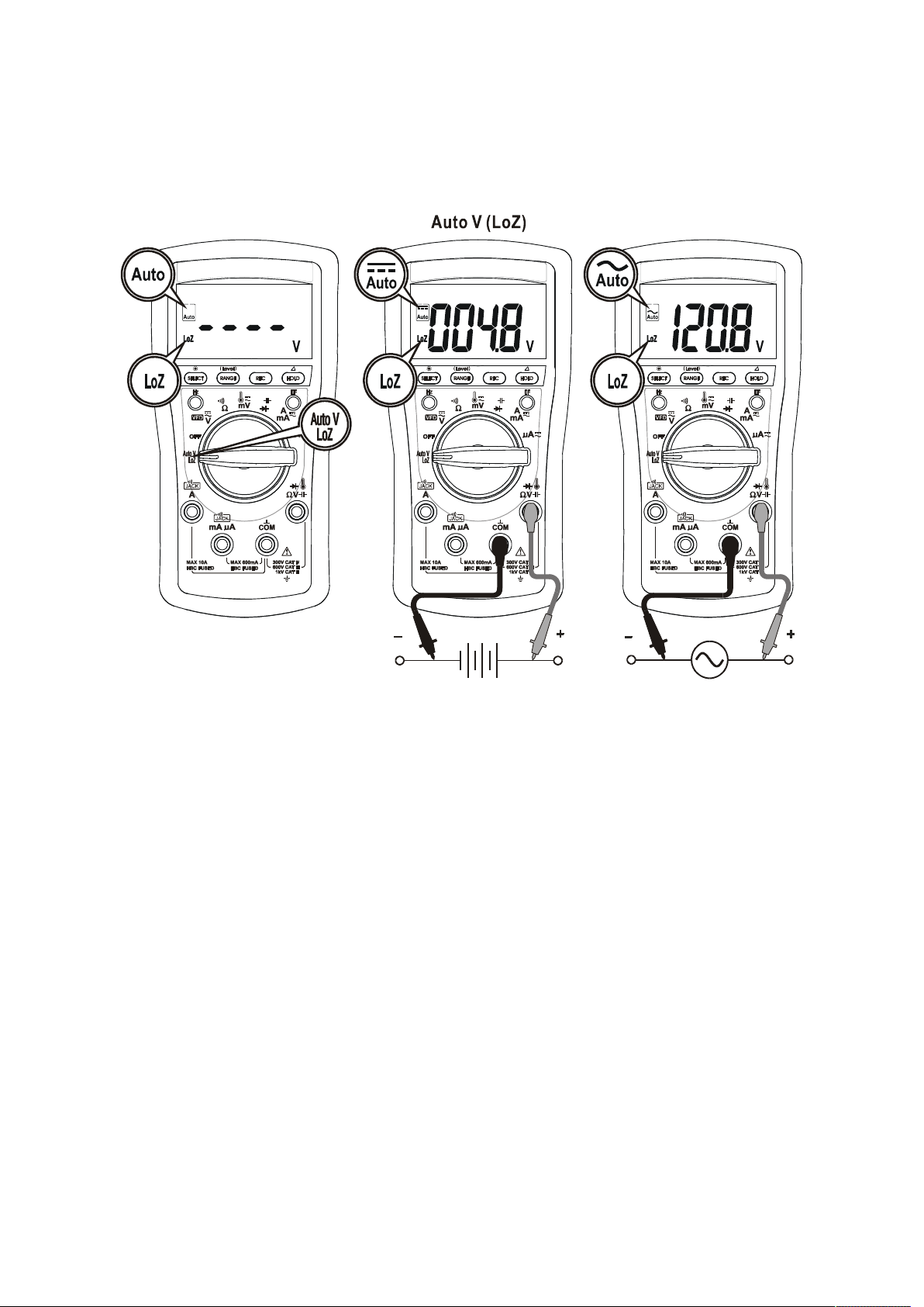
AutoV (LoZ) (Model 235 only)
AutoV automatically selects measurement function of DCV or ACV based, on their
input levels via the test leads. The input also provides a low ramp-up impedance (LoZ)
to drain ghost voltages*.
●With no input, the meter displays “- - - -” when it is ready.
●When a signal above the voltage threshold of 1V DC or AC up to the rated 1000V is
present, the meter displays the voltage value in appropriate DC or AC, whichever
larger in peak magnitude.
Note:
*Ghost-voltage Buster: Ghost-voltages are unwanted stray signals coupled from
adjacent hard signals, which confuse common multimeter voltage measurements. The
AutoV mode provides low (ramp-up) input impedance (approx. 2.1kΩ at low voltage)
to drain ghost voltages leaving mainly hard signal values on meter readings. It is an
invaluable feature for precise indication of hard signals, such as distinguishing between
hot and open wires (to ground) in electrical installation applications.
*Only HOLD, EF & Backlight push-button features are available in AutoV mode.
Page 7
6
WARNING:
AutoV mode input impedance increases abruptly from initial 2.1kΩ to a few hundred
kΩ’s on high voltage hard signals. “LoZ” displays on the LCD to remind the users of
being in such low impedance mode. Peak initial load current, while probing 1000VAC
for example, can be up to 673mA (1000V x 1.414 / 2.1kΩ), decreasing abruptly to
approx. 2.4mA (1000V x 1.414 / 580kΩ) within a fraction of a second. Do not use
AutoV mode on circuits that could be damaged by such low input impedance. Instead,
use rotary selector or high input impedance voltage modes to minimize loading for
such circuits.
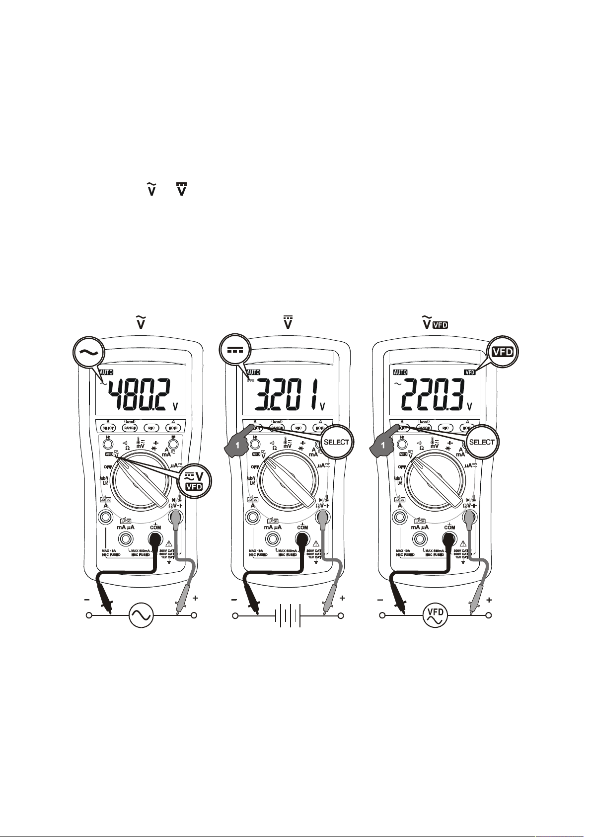
ACV, DCV & VFD-ACV
Press the SELECT button momentarily to select the subject functions in sequence.
Last selection will be saved as power up default for repeat measurement convenience.
Note:
VFD-ACV and the associated Hz are equipped with digital low-pass filter (DSP), and
are capable of handling VFD (Variable Frequency Drives) signals for fundamental V &
Hz readings. It also improves ACV and Hz reading stability when being used in most
noisy electrical environments.
Page 8
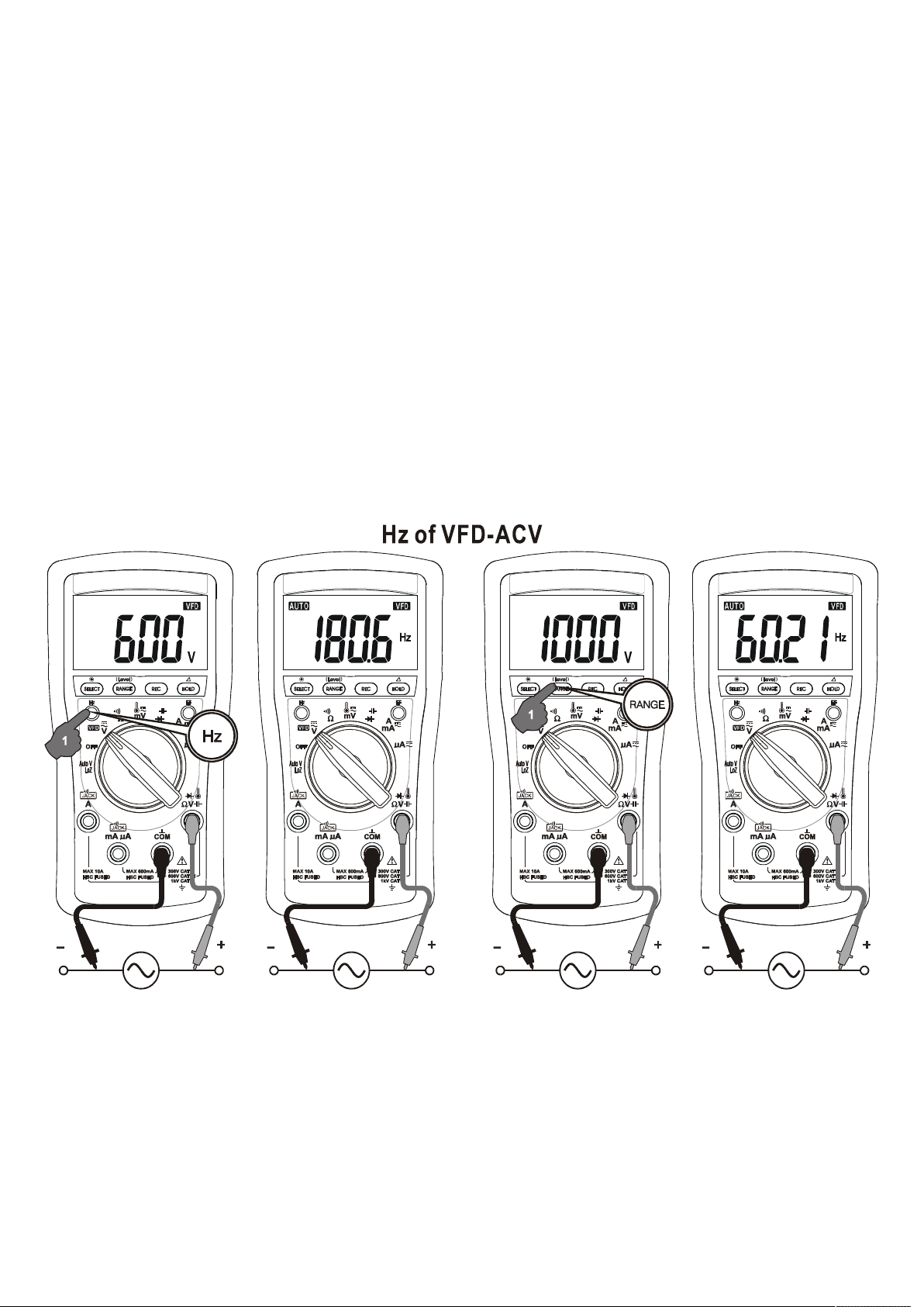
7
Line Frequency (Models 233 & 235 only)
Press the Hz push-button momentarily to toggle Hz function. It is only available to
Voltage and Current related ranges.
Input sensitivity varies automatically with the function range selected while activating
the Hz function. 6V function range has the highest and the 1000V range has the
lowest. When activated under DCV, ACV or VFD-ACV voltage function, the trigger
voltage range will be displayed right before starting the Hz readings. Press
momentarily the RANGE button can manually select another trigger voltage range (not
available to current ranges). It is recommended to first measure the signal voltage (or
current) level and activate Hz function in that range to get the most appropriate trigger
level. If the Hz reading becomes unstable, select lower sensitivity to avoid electrical
noise. If the reading shows zero, select higher sensitivity.
Page 9
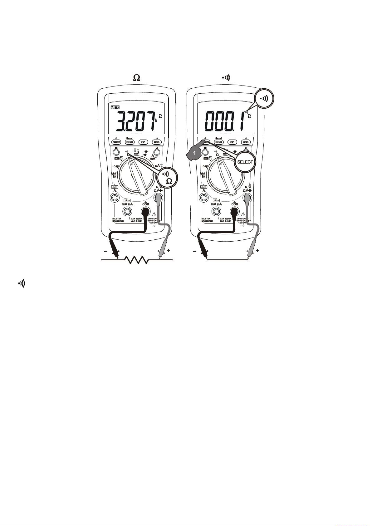
Resistance & BeepLitTM Continuity
Press the SELECT button momentarily to toggle the functions. Last selection will be
saved as power up default for repeat measurement convenience.
8
BeepLitTM Continuity function is having improved convenience for checking wiring
connections and operation of switches. A continuous beep tone together with flashing
display backlight indicate a complete wire. Such audible and visible indications improve
continuity readabilities in noisy working environments.
CAUTION
Using resistance and continuity function in a live circuit will produce false results and
may damage the instrument. In many cases the suspected component must be
disconnected from the circuit to obtain an accurate reading
Page 10
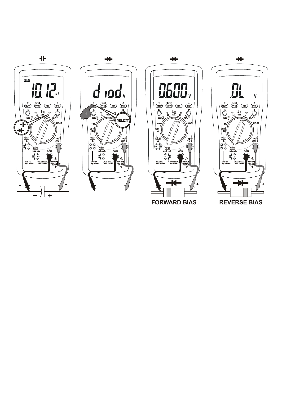
Capacitance (Models 235 & 233 only); Diode
Press the SELECT button momentarily to toggle the functions. Last selection will be
saved as power up default for repeat measurement convenience.
9
In Diode function, the normal forward voltage drop (forward biased) for a good silicon
diode is between 0.400V to 0.900V. A reading higher than that indicates a leaky diode
(defective). A zero reading indicates a shorted diode (defective). An OL indicates an
open diode (defective). Reverse the test leads connections (reverse biased) across the
diode. The digital display shows OL if the diode is good. Any other readings indicate
the diode is resistive or shorted (defective).
CAUTION
Discharge capacitors before making any measurement. Large value capacitors should
be discharged through an appropriate resistance load.
Page 11
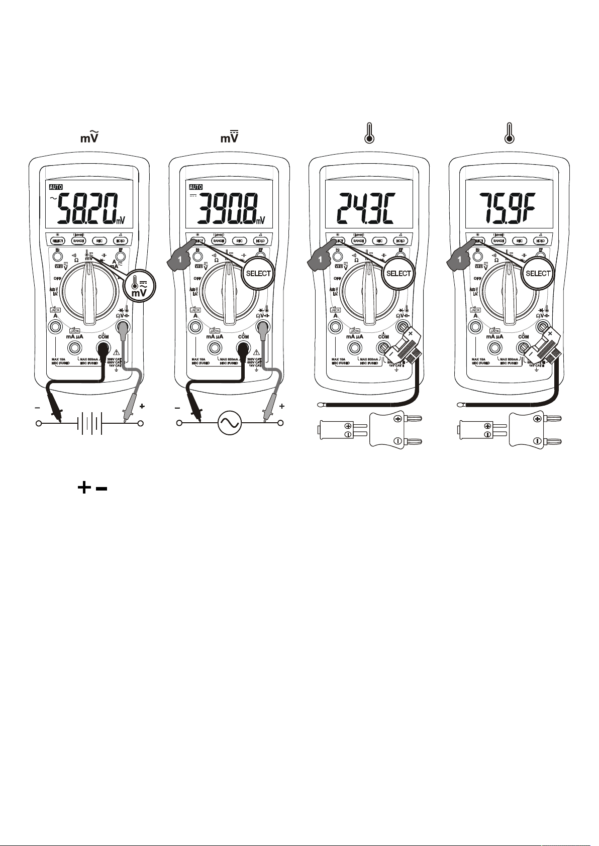
10
ACmV & DCmV; Temperature oC & oF (Model 235 only)
Press the SELECT button momentarily to select the subject functions in sequence.
Last selection will be saved as power up default for repeat measurement convenience.
Note: Be sure to insert the banana plug type-K temperature bead probe Bkp60 with
correct polarities. You can also use a plug adapter Bkb32 (Optional purchase)
with banana pins to type-K socket to adapt other standard type-K mini plug
temperature probes.
Page 12
11
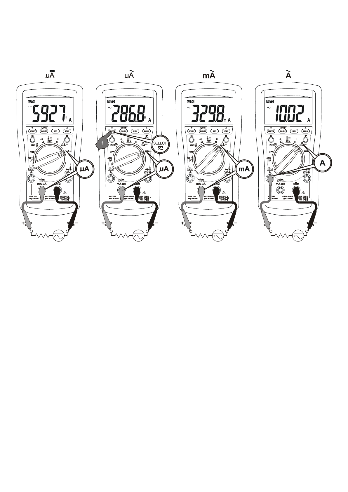
A, mA and A Current
Press SELECT button momentarily to toggle between DC and AC. Last selection will
be saved as power up default for repeat measurement convenience.
Application notes for flame sensors:
DCA function is useful for HVAC/R flame sensor applications. The 0.1A resolution
can identify the minute current changes in flame detector applications. Flame signal
current check should indicate steady flame signal of at least 2A for a rectification
type, or 1.5A for an ultraviolet type (8A for self checking systems). If a flame signal
current with inadequate strength or fluctuation beyond 10%, check the following to
avoid the risk of unwanted flame relay dropout :
For gas or oil flames (Minipeeper):
Low supply voltage
Detector location
Defective detector wiring
Dirty viewing windows
Faulty Minipeeper
For oil flames (Photocell):
Detector location & wiring
Page 13

Smoky flame or poorly adjusted air shutter
Faulty Photocell
Temperature over 165 oF (74 oC) at photocell
For gas flames (Flame Rod):
Ignition interference (A flame signal current difference with the ignition both on and
off greater than 0.5A indicates the presence of ignition interference)
Insufficient ground (must be at least 4 times the detector area)
Flame lifting off burner head (ground), or not continuously in contact with the flame
rod
Temperature in excess of 600 oF (316 oC) at the flame electrode insulator causing
short to ground.
12
Page 14
13
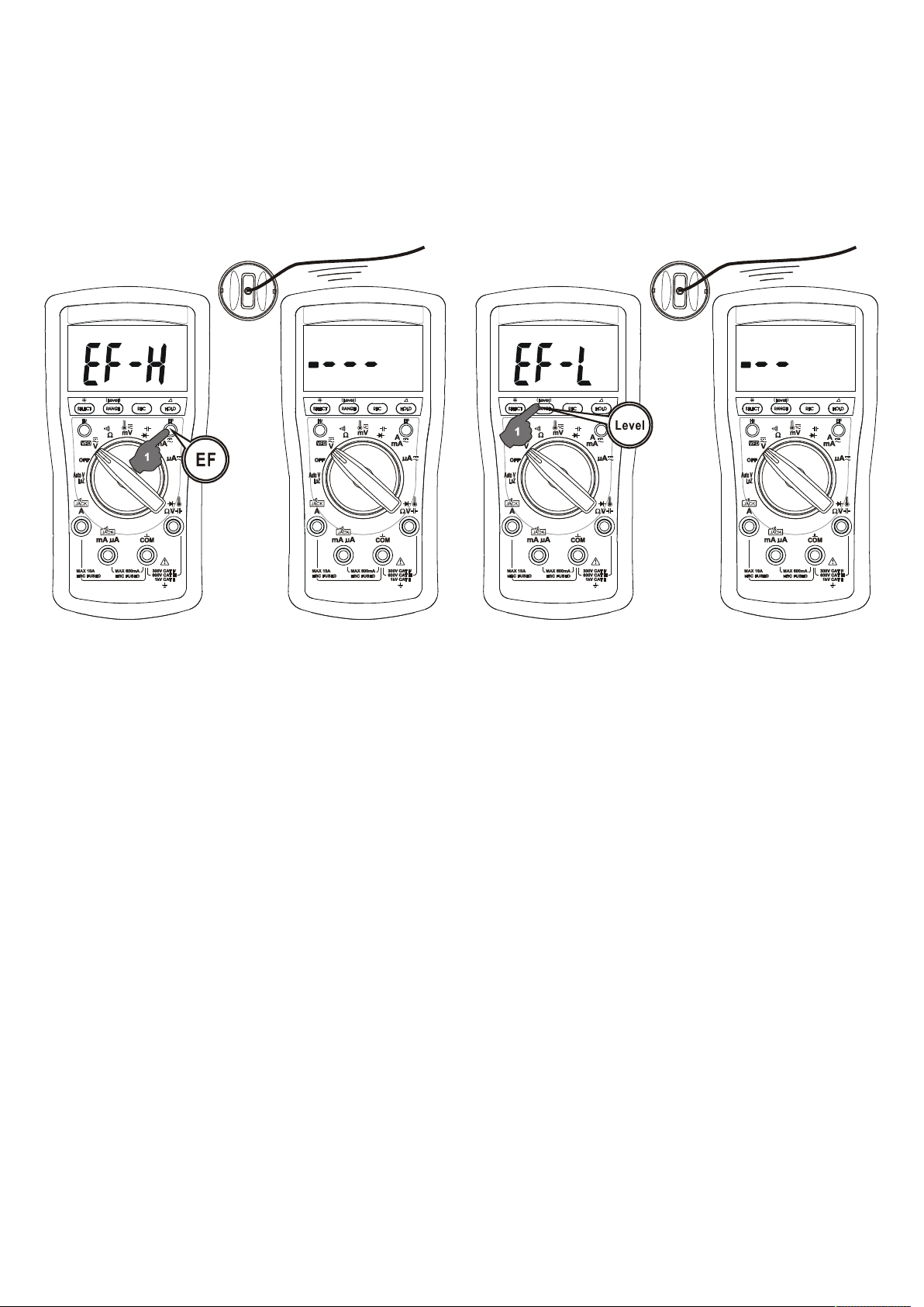
Electric Field EF-Detection
Press the EF button momentarily to toggle EF-Detection feature. The meter displays
“EF-H” when it is ready. If it is too sensitive for your applications, press (Level) button
momentarily toggles to lower sensitivity “EF-L”. The detected Electric Field strength is
indicated as a series of bar-graph segments on the display plus variable beep tones.
●Non-Contact EF-Detection: An antenna is located along the top-left end of the
meter, which detects electric field surrounding energized live conductors. It is ideal for
tracing live wiring connections, locating wiring breakages and to distinguish between
live and earth connections.
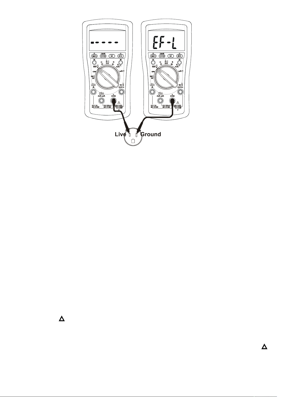
●Probe-Contact EF-Detection: For more precise indication of live wires, such as
distinguishing between Live and Ground connections, use direct contact testing with
one single test-probe via the input terminal COM or V. The COM terminal (Black) has
the best sensitivity.
Page 15
14
MAX/MIN/AVG Record mode
Press REC button momentarily to activate MAX/MIN/AVG recording mode. The LCD
“MAX MIN AVG” turn on. The meter beeps when new MAX (maximum) or MIN
(minimum) reading is updated. Press the button momentarily to read the MAX, MIN,
AVG readings in sequence. Press the button for 1 second or more to exit
MAX/MIN/AVG recording mode. Auto-ranging remains, and Auto-Power-Off is disabled
automatically in this mode.
Backlighted LCD display
Press the SELECT button for 1 second or more to toggle the LCD backlight. The
backlight will also be turned off automatically after 10 minutes to extend battery life.
Hold
The hold feature freezes the display for later view. Press the HOLD button momentarily
to toggle the hold feature.
Relative Zero ( ) mode
Relative Zero allows the user to offset the meter consecutive measurements with the
displaying reading as the reference value. Practically all displaying readings can be set
as relative reference value including MAX/MIN/AVG feature readings. Press the
button for one second or more to toggle Relative Zero mode.
Page 16

15
Manual or Auto-ranging
For most auto-ranging functions (LCD turns on by default), press the RANGE
button momentarily to select manual-ranging override. The meter will remain in the
range it was in, the LCD turns off. Press the button momentarily again to select
the next range. Press and hold the button for 1 second or more to resume autoranging.
Note: Manual-ranging feature is not available to Auto-V, Capacitance & Hz functions.
Beep-Jack™ Input Warning
The meter beeps as well as displays “InEr” to warn the user against possible damage
to the meter due to improper connections to the A, mA, or A input jacks when another
function, especially a voltage function, is selected.
Intelligent Auto-Power-Off (APO)
The Auto-Power-off (APO) mode turns the meter off automatically to extend battery life
after approximately 32 minutes of no specified activities, where applicable:
1) Rotary switch or push button operations
2) Significant measuring readings of above 8.5% of ranges
3) Non-OL readings for Resistance, Continuity or Diode function
4) Non-zero readings for Hz function
5) Electric field signal present for EF function
6) Significant movement indication as in Phase Rotation functions
In other words, the meter will intelligently avoid entering the APO mode when it is
under normal measurements. To wake up the meter from APO, press the SELECT
button momentarily and release, or turn the rotary switch OFF and then back on.
Always turn the rotary switch to the OFF position when the meter is not in use
5) MAINTENANCE
WARNING
To avoid electrical shock, disconnect the meter from any circuit, remove the test leads
from the input jacks and turn OFF the meter before opening the case. Do not operate
with open case. Install only the same type of fuse(s) or equivalent
Cleaning and Storage
Periodically wipe the case with a damp cloth and mild detergent; do not use abrasives
or solvents. If the meter is not to be used for periods of longer than 60 days, remove
the battery and store it separately
Page 17
16
Trouble Shooting
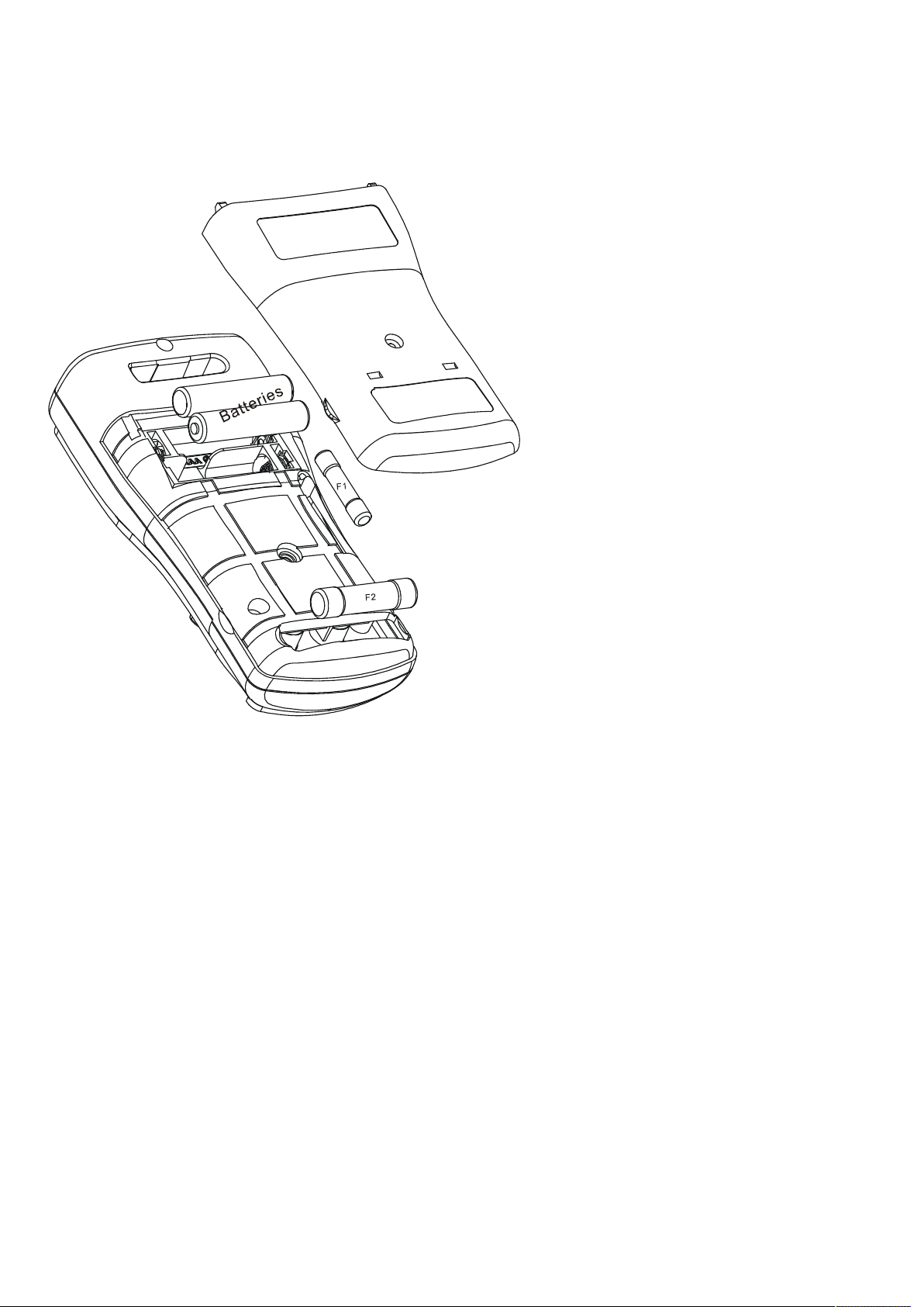
If the instrument fails to operate, check battery, fuses, leads, etc., and replace as
necessary. Double check operating procedure as described in this user’s manual
Battery use:
1.5V AAA Size battery x 2
Fuses use:
Fuse F1 for AmA current input:
0.4A/1000V DC/AC, IR
30kA F fuse or better;
Dimension: 6 x 32 mm
Fuse F2 for A current input:
11A/1000V DC/AC, IR 20kA F
fuse or better; Dimension: 10 x
38mm
Battery and Fuse replacement:
Loosen the screw from the
access cover of the case bottom.
Lift the access cover. Replace
the batteries or fuse(s). Re-fasten
the screw.
Page 18

17
GENERAL SPECIFICATION
Display: 3-5/6 digits 6,000 counts
Update Rate: 5 per second nominal
Operating Temperature: -10oC to 45oC
Relative Humidity: Maximum relative humidity 80% for temperature up to 31oC
decreasing linearly to 50% relative humidity at 45oC
Altitude: Operating below 2000m
Storage Temperature: -20oC ~ 60oC, < 80% R.H. (with battery removed)
Temperature Coefficient: Nominal 0.15 x (specified accuracy)/ oC @ (-10oC ~ 18oC or
28oC ~ 45oC), or otherwise specified
Sensing: True RMS sensing
Ingress Protection: IP40
Pollution Degree: 2
Safety: Certified per IEC/UL/EN61010-1 Ed. 3.0, IEC/UL/EN61010-2-030 Ed. 1.0,
IEC/UL/EN61010-2-033 Ed. 1.0, IEC/UL/EN61010-031 Ed. 1.1 and the corresponding
CAN/CSA-C22.2 regulations to Measurement Categories:
CAT II 1000V, CAT III 600V and CAT IV 300V AC & DC
Transient Protection: 6.0kV (1.2/50s surge)
E.M.C. : Meets EN61326-1:2013
In an RF field of 3V/m:
Temperature function is not specified
Ohm function:
Total Accuracy = Specified Accuracy + 15 digits
Other functions:
Total Accuracy = Specified Accuracy
Performance above 3V/m is not specified
Overload Protection:
A & mA: 0.4A/1000V DC/AC rms, IR 30kA, F fuse or better
A: 11A/1000V DC/AC rms, IR 20kA, F fuse or better
V & AutoV: 1100V DC/AC rms
mV, Ohm & others: 1000V DC/AC rms
Low Battery: Below approx. 2.5V
Power Supply: 1.5V AAA Size battery X 2
Power Consumption (typical): 3.2mA
APO Consumption (typical): 10A
APO Timing: Idle for 30 minutes
Dimension: 161*80*50mm L*W*H (With Holster)
Weight: Approx. 334 gm (With Holster)
Page 19
18
Special Features: AutoV (LoZ) (Model 235 only); VFD; BeepLitTM Continuity; Auto-
ranging MAX/MIN/AVG Record; Backlighted LCD; Auto-ranging Relative Zero mode;
Display Hold; EF-Detection (NCV); BeepJack™ on AmA/A terminals
Accessories: Test lead pair; Batteries installed; User’s manual; BKP60 banana plug type-K
thermocouple (Model 235 only)
Optional Purchase Accessories: BKB32 banana plug to type-K socket plug adaptor
(Model 235 only); BMH-01 magnetic hanger; BMP-25x soft carrying pouch
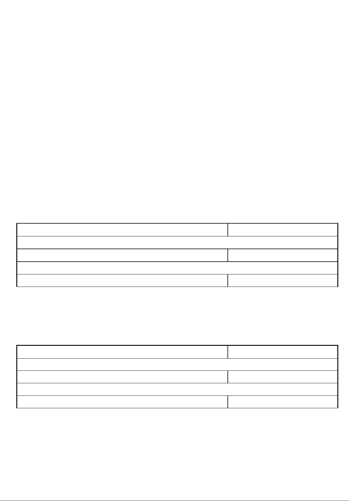
Electrical Specification
Accuracy is given as (% of reading digits + number of digits) or otherwise specified @
23oC 5oC
ACV & ACA accuracies are specified from 1 % to 100 % of range or otherwise
specified. Maximum Crest Factor <2:1 at full scale & <4:1 at half scale, and with
frequency components fall within the meter specified frequency bandwidth for nonsinusoidal waveforms
AC Voltage
RANGE Accuracy
50Hz ~ 60Hz
6.000V
1)
, 60.00V, 600.0V, 1000V 0.7% + 3d
45Hz ~ 440Hz
6.000V
1)
, 60.00V, 600.0V, 1000V 2.0% + 3d
Input Impedance: 10M, 54pF nominal
1)
<5d non-zero residue may appear when backlight is on, which will not affect the
specified measuring range and accuracy
ACmV
RANGE Accuracy
10Hz ~ 500Hz
60.00mV
1) 2)
, 600.0mV
3)
1.0% + 3d
500Hz ~ 800Hz
60.00mV
1) 2)
, 600.0mV
3)
2.0% + 3d
Input Impedance: 10M, 54pF nominal
1)
<5d non-zero residue may appear when backlight is on, which will not affect the
specified measuring range and accuracy
2)
Signal peak absolute values, including DC bias, less than 130mV
3)
Signal peak absolute values, including DC bias, less than 1300mV
peak
peak
Page 20
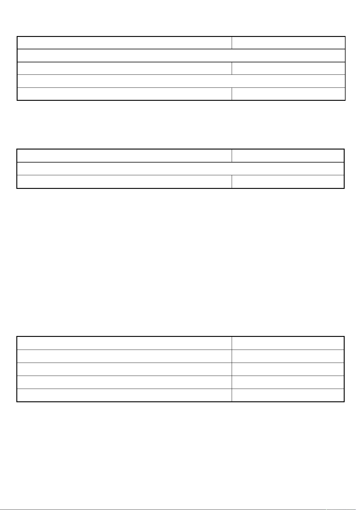
VFD_ACV (with Low Pass Filter )
RANGE Accuracy
10Hz ~ 100Hz (fundamental)
600.0V, 1000V 1.0% + 3d
100Hz ~ 400Hz (fundamental)
600.0V, 1000V 10% + 3d
1)
Not specified for fundamental frequency > 400Hz
2)
Accuracy linearly decreases from 1% + 3d @100Hz to 10% + 3d @400Hz
AutoV_ACV (Model 235 only)
19
1)
2)
RANGE Accuracy
1)
45Hz ~ 440Hz
600.0V, 1000V 2.0% + 3d
1)
Not specified at <1VAC
Threshold: > 1VAC nominal
Input Impedance:
Initially approx. 2.1k, 164pF nominal; Impedance increases abruptly within a
fraction of a second as display voltage is above 50V (typical). Ended up impedances
vs display voltages typically are:
12k @100V
100k @300V
240k @600V
580k @1000V
DC Voltage
RANGE Accuracy
60.00mV, 600.0mV, 6.000V 0.3% + 2d
60.00V 0.4% + 2d
600.0V 0.2% + 2d
1000V 0.4% + 2d
Input Impedance: 10M, 54pF nominal
Page 21
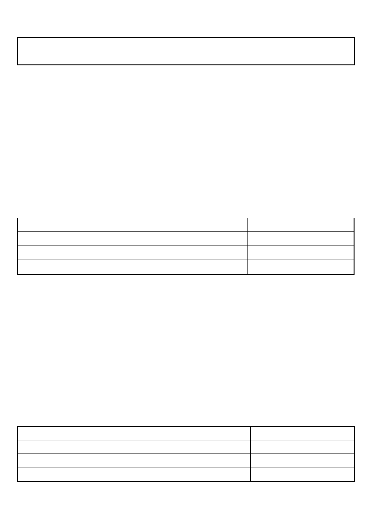
AutoV_DCV (Model 235 only)
20
RANGE Accuracy
1)
600.0V, 1000V 2.0% + 3d
1)
Not specified at <1VDC
Threshold: > +1.0VDC or < -1.0VDC nominal
Input Impedance:
Initially approx. 2.1k, 164pF nominal; Impedance increases abruptly within a
fraction of a second as display voltage is above 50V (typical). Ended up impedances
vs display voltages typically are:
12k @100V
100k @300V
240k @600V
580k @1000V
Ohm
RANGE
1)
Accuracy
600.0, 6.000k
60.00k, 600.0k
6.000M
1)
Open Circuit Voltage: 1.6VDC typical
2)
Constant Test Current: 0.2A Typical
3)
Constant Test Current: 0.02A Typical
4)
5%+20d @ >30M
2)
, 60.00M
3)
BeepLit™ Continuity Tester
Continuity Threshold: Between 30 and 480
Continuity ON Response Time: <15ms
Audible Indication: Beep sound
Visible Indication: LCD Backlight
Capacitance (Models 233 & 235 only)
0.3% + 3d
0.5% + 3d
0.9% + 2d
4)
RANGE Accuracy
20.00nF, 200.0nF 1.5% + 8d
2000nF, 20.00F, 200.0F, 2000F
1.5% + 2d
10.00mF 4.5% + 10d
Accuracies with film capacitor or better
Page 22
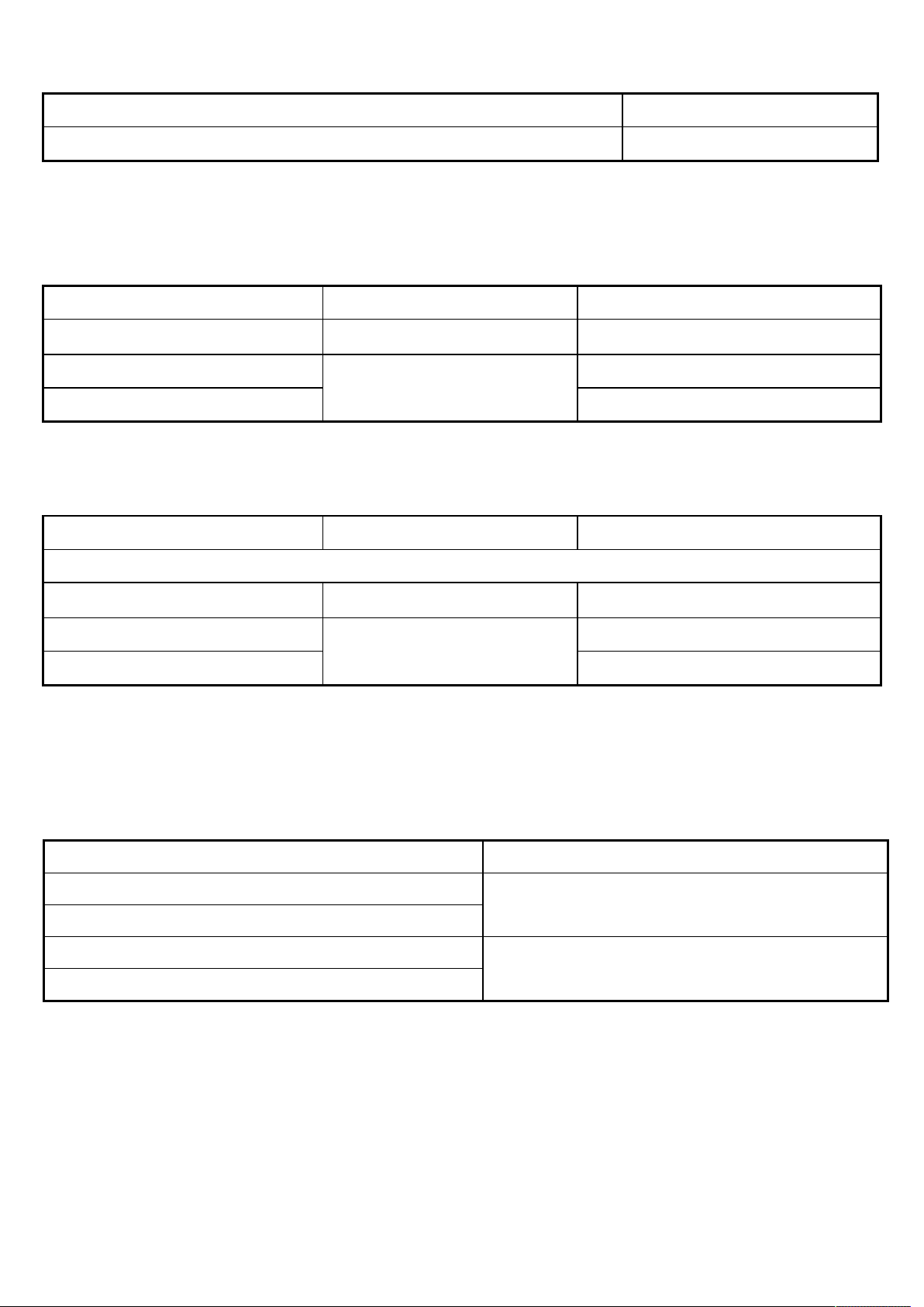
Diode Tester
RANGE Accuracy
3.000V 0.9% + 2d
Test Current: 0.3mA typical
Open Circuit Voltage: < 3.2VDC typical
DC Current
RANGE Accuracy Burden Voltage
21
600.0A, 6000A
60.00mA, 600.0mA
6.000A, 10.00A
1)
10A continuous, >10A to 20A for 30 seconds max with 5 minutes cool down interval
1)
0.04V/A
1.0% + 3d
0.7% + 3d
0.1mV/A
1.9mV/mA
AC Current
RANGE Accuracy Burden Voltage
50HZ ~ 400HZ
600.0A, 6000A
60.00mA, 600.0mA
6.000A
1)
<5d non-zero residue may appear when backlight is on, which will not affect the
1)
, 10.00A
2)
0.04V/A
1.5% + 3d
1.0% + 3d
0.1mV/A
1.9mV/mA
specified measuring range and accuracy
2)
10A continuous, >10A to 20A for 30 seconds max with 5 minutes cool down interval
Temperature (Model 235 only)
RANGE Accuracy
1) 2)
-40.0 oC ~ 99.9oC
1% + 1 oC
100 oC ~ 400oC
-40.0 oF ~ 99.9 oF
1% + 2 oF
100 oF ~ 752 oF
1)
Accuracies assume meter interior and the ambient have reached the same
temperature (isothermal stage) for a correct junction voltage compensation. Allow
enough settling time for a significant change of ambient temperature. It can take up to
an hour for changes > 5°C.
2)
Type-K thermocouple range & accuracy not included
Page 23
Line Frequency (Models 233 & 235 only)
Function Sensitivity (Sine RMS) Range
60mV, 600mV 50mV 10Hz - 50kHz
6V 5V 10Hz - 50kHz
60V 10V 10Hz - 50kHz
600V 50V 10Hz - 1kHz
1000V 500V 10Hz - 1kHz
VFD 600V 50V 10Hz - 1kHz
VFD 1000V 500V 10Hz - 1kHz
22
600A, 6000A 500A
10Hz - 5kHz
60mA, 600mA 50mA 10Hz - 5kHz
6A, 10A 8A 50Hz - 1kHz
Accuracy: 0.03% + 2d
Non-Contact EF-Detection (Models 237R & 239R only)
Bar-Graph
Indication
-
- -
- - -
- - - -
- - - - -
EF-H (Hi Sensitivity) EF-L (Lo Sensitivity)
Typical Voltage (Tolerance)
10V (3V ~ 19V) 40V (16V ~ 71V)
20V (10V ~ 38V) 80V (32V ~ 142V)
40V (21V ~ 79V) 160V (63V ~ 285V)
80V (40V ~ 156V) 300V (105V ~ 608V)
160V (>80V) 500V (>300V)
Indication: Bar-graph segments & audible beep tones proportional to the field strength
Detection Frequency: 50/60Hz
Detection Antenna: Top-left end of the meter
Probe-Contact EF-Detection: For more precise indication of live wires, such as
distinguishing between live and ground connections, use direct contact testing with one
single test-probe via the input terminal COM or V. The COM terminal (Black) has the
best sensitivity.
Page 24

LIMITED WARRANTY
BRYMEN warrants to the original product purchaser that each product it manufactures will
be free from defects in material and workmanship under normal use and service within a
period of one year from the date of purchase. BRYMEN's warranty does not apply to
accessories, fuses, fusible resistors, spark gaps, batteries or any product which, in
BRYMEN's opinion, has been misused, altered, neglected, or damaged by accident or
abnormal conditions of operation or handling.
To obtain warranty service, contact your nearest BRYMEN authorized agent or send the
product, with proof of purchase and description of the difficulty, postage and insurance
prepaid, to BRYMEN TECHNOLOGY CORPORATION. BRYMEN assumes no risk for
damage in transit. BRYMEN will, at its option, repair or replace the defective product free of
charge. However, if BRYMEN determines that the failure was caused by misused, altered,
neglected, or damaged by accident or abnormal conditions of operation or handling, you will
be billed for the repair.
THIS WARRANTY IS EXCLUSIVE AND IS IN LIEU OF ALL OTHER WARRANTIES,
EXPRESSED OR IMPLIED, INCLUDING BUT NOT LIMITED TO ANY IMPLIED
WARRANTY OR MERCHANTABILITY OR FITNESS FOR A PARTICULAR PURPOSE OR
USE. BRYMEN WILL NOT BE LIABLE FOR ANY SPECIAL, INDIRECT, INCIDENTAL OR
CONSEQUENTIAL DAMAGES.
BRYMEN TECHNOLOGY CORPORATION
TEL:+886 2 2226 3396
FAX:+886 2 2225 0025
http://www.brymen.com
PRINTED ON RECYCLABLE PAPER, PLEASE RECYCLE
COPYRIGHT © MMXV BTC, ALL RIGHTS RESERVED
P/N: 7M1C-1501-0000 PRINTED IN TAIWAN
 Loading...