

Page 1
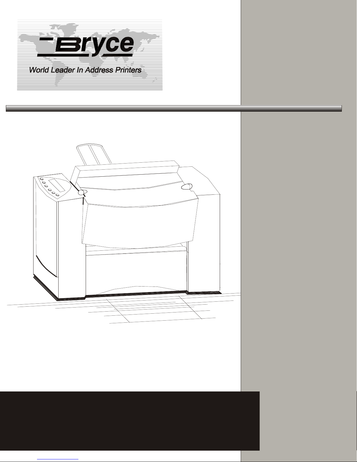
9K-L9K-L
Users ManualUsers Manual
Page 2

WARNING
WARNING: HIGH VOLTAGES ARE PRESENT BEHIND THE COVERS AND IN THE PAN ASSEMBLY.
Never remove the pan access cover assembly or rear cover assembly since there are no user serviceable parts
inside. The electrical and/or sensitive parts may only be serviced by an authorized Service Representative.
Important Safeguards :Read all instructions before attempting to operate this equipment.
To reduce the risk of fire and/or electric shock, do not attempt to disassemble this machine.
The machine is not intended for use in hazardous locations. Do not use in environments known to
contain flammable or explosive gases.
To prevent overheating, do not cover vent openings or use the machine over a radiator or heat register.
To reduce the risk of injury, refer all non-operator service functions to qualified service personnel.
Access only those operator designated areas of machine for jam clearing. All other areas of machine
requiring disassembly or removal of covers should only be accessed by qualified service personnel.
This machine cabinet serves to enclose hazardous parts. If the machine has been dropped or otherwise
had the cabinet stressed in any way, report it to your local service representative.
In the performance of operator service procedures, be certain the machine is unplugged from the wall.
Do not attempt to use this product in an unauthorized manner. To do so may expose you to mechanical
and / or electrical hazards.
Do not expose power cord to sharp points or edges.
To protect against shock, the power cord must only be plugged into a grounded receptacle. The ground
pin on the plug must never be removed.
The power cord should be routed so it cannot be walked upon.
Do not operate this machine with a damaged power cord or plug.
Unplug or otherwise disable this machine before cleaning.
Know how to turn off power in the work area, and to summon help in the event of an emergency.
Do not remove safety covers for cleaning, adjustments or repairs. Call your service representative.
Keep office supplies such as paper clips, staples, rubber bands, etc., away from machine.
Keep loose clothing ties, jewelry, and long hair away from moving parts of this machine.
Ink formulations for use in this machine are critical. Use only those specified.
Notice: Changes or modifications to this unit not expresslyapproved by the party responsible for
compliance could void the user’s authority to operate the equipment.
Treat every circuit as if it were live. Check first with a neon tester or a voltmeter.
Federal Communications Commission Compliance
"This device complies with Part 15 of the FCC Rules. Operation is subject to the following two conditions:
1). This device may not cause harmful interference, and
2). This device must accept any interference received, including interference that may cause
undesired operation.
Page 3
NOTE: This equipment has been tested and found to comply with FCC Rules Part 15 subpart B Class B for a digital
device. These limits are designed to provide reasonable protection against harmful interference in a residential installation. This
equipment generates, uses, and can radiate radio frequency energy and, if not installed and used in accordance with the
instructions, may cause harmful interference to radio communications. If this equipment does cause harmful interference to radio
or television reception, which can be determined by turning the equipment off and on, the user is encouraged to try to correct the
interference by one or more of the following measures:
Reorient or relocate the receiving antenna.
- Increase t he separation between the equipment and receiver.
- Connect the equipment into an outlet on a circuit different from that to which the receiver is connected.
- Consult the dealer or an experienced radio / TV technician for help.
Shielded cables must be used with this unit t o ensure compliance with the Class B FCC limits.
Canadian DOC Compliance.
"This Class B digital apparatus meets all requirements of the Canadian Interference-Causing Equipment Regulations.
Cet appareil numérique de la classe B respecte toutes les exigences du Règlement sur le matériel brouilleur du
Canada.
Caution
Danger of explosion if battery is incorrectly replaced. Replace only with the same or equivalent type recommended by the
manufacturer. Dispose of used batteries according to the manufacturer’s instructions.
VORSICHT
Explosionsgefahr bei unsachgemäßem Austausch der Batterie.
Ersatz nur durch denselben oder einen vom
Hersteller empfohlenen gleichwertigen Typ.
Entsorgung gebrauchter Batterien nach
Angaben des Herstellers.
ADVARSEL
Lithiumbatteri − Eksplosionsfare ved fejlagtig håndtering.
Udskiftning må kun ske med batteri af samme fabrikat og type.
Levér det brugte batteri tilbage tilleverandøren.
Notice
The information in this document is subject to change without notice. Bryce Office Systems makes no warranty of
any kind with regard to the material contained herein. Bryce Office Systems will not be liable for incidental or
consequential damages in connection with the furnishing, performance or use of this material.
Page 4
TABLE OF CONTENTS
FOREWORD
INTRODUCTION
UNPACKING Chapter 1
UNPACKING................................................................................................1 - 1
PARTS OF THE PRINTER Chapter 2
THE PARTS OF THE PRINTER..................................................................2 - 1
INPUT BIN........................................................................................2 - 1
CONTROL PANEL & PRINT STATION........................................2 - 1
PAPER CATCH ASSEMBLY ..........................................................2 - 1
ASSEMBLY OF PRINTER COMPONENTS Chapter 3
CHOOSING A GOOD LOCATION FOR THE PRINTER..............3 - 1
REMOVING PROTECTIVE MATERIALS.....................................3 - 1
INSTALLATION OF THE WIRE FORM ASSEMBLY..................3 - 2
INSTALLING THE SLIDING FENCE ............................................3 - 3
CONNECTING THE PRINTER.......................................................3 - 4
CONNECTING THE POWER CORD..............................................3 - 5
OPERATING THE PRINTER Chapter 4
POWER ON...................................................................................................4 - 1
INSTALLING AN INK JET CARTRIDGE......................................4 - 1
REMOVING AN INK JET CARTRIDGE........................................4 - 4
PREPARING THE MEDIA ..............................................................4 - 5
MEDIA TYPES.................................................................................4 - 6
SETTING THE PROPER FEED GAP..............................................4 – 7
SETUP WITH #10 ENVELOPES.....................................................4 - 8
WIRE FORM ADJUSTMENTS........................................................4 - 8
WIRE FORM CENTER ADJUSTMENT .........................................4 - 9
WIRE FORM HEIGHT ADJUSTMENT..........................................4 - 9
FEED RAMP ADJUSTMENT..........................................................4 - 10
SLIDING FENCE ADJUSTMENT...................................................4 - 10
PRINTER TIPS Chapter 5
ADJUSTING THE EXIT ROLLER SLIDER...................................5 - 1
OUTPUT STACK HEIGHT..............................................................5 - 1
ADJUSTMENT LEVER FINE TUNING .........................................5 - 2
Revision A 9K-L USERS MANUAL Section i - 1
P/N 90-00860-001
Page 5

TABLE OF CONTENTS
PRINTER MENU SYSTEM Chapter 6
KEYPAD DEFINITIONS .............................................................................6 - 1
HOW TO USE THE MENUS .......................................................................6 - 2
MAIN MENU................................................................................................6 - 4
• 1. ADDRESS LAYOUT.............................................................6 - 4
• 2. PRINT QUALITY..................................................................6 - 9
• 3. FONT......................................................................................6 - 10
• 4. BARCODE .............................................................................6 - 15
• 5. ADDRESS RECOVERY........................................................6 - 17
• 6. CLEAR COUNTER................................................................6 - 19
• 7. JOB SETTINGS......................................................................6 - 19
SETUP MENU...............................................................................................6 - 21
• 1. HEAVY MEDIA MODE........................................................6 - 21
• 2. TEST PRINT HEAD ..............................................................6 - 22
• 3. PURGE PRINT HEAD...........................................................6 - 22
• 4. LINES PER ADDRESS..........................................................6 - 23
• 5. COMMUNICATIONS ...........................................................6 - 24
A. BAUD RATE ......................................................................6 - 25
B. PARITY...............................................................................6 - 25
C. WORD LENGTH................................................................6 - 26
D. LINE TERMINATION ....................................................... 6 - 26
• HANDSHAKING PROTOCOL..................................................6 - 27
• ESTABLISHING COMMUNICATIONS...................................6 - 27
• VERIFYING COMMUNICATIONS..........................................6 - 27
• 6. HEX DUMP MODE...............................................................6 - 28
• 7. LANGUAGE ..........................................................................6 - 29
A. SYMBOL SET ....................................................................6 - 30
B. INCH / MILLIMETER........................................................6 - 30
C. MENU LANGUAGE ..........................................................6 - 31
• 8. ENV. FEED DELAY..............................................................6 - 31
• 9. ENV. AUTO EJECT...............................................................6 - 32
• 10. ROM REVISION #...............................................................6 - 32
TROUBLESHOOTING AND MAINTENANCE Chapter 7
DIAGNOSTIC CHART.................................................................................7 - 1
PREVENTATIVE MAINTENANCE ...........................................................7 - 6
FEED ROLLERS...............................................................................7 - 6
PRINT CARTRIDGE........................................................................7 - 6
SENSORS..........................................................................................7 - 6
Revision A 9K-L USERS MANUAL Section i - 2
P/N 90-00860-001
Page 6

TABLE OF CONTENTS
FLOOR ASSEMBLY AND COVERS..............................................7 - 7
PRINT HEAD ASSEMBLY..............................................................7 - 7
EXIT ROLLER SLIDERS.................................................................7 - 7
PRINTER MENUS APPENDIX A
9K-L MAIN MENU ......................................................................................A - 1
9K-L SETUP MENU.....................................................................................A - 3
HEX CHART APPENDIX B
HEX CHART.................................................................................................B - 1
PRINTER CONTROL COMMANDS APPENDIX C
PCL COMMAND CODES............................................................................C - 1
CHARACTER SET APPENDIX D
9K-L CHARACTER SET..............................................................................D - 1
COMPUTER INTERFACE WIRING DIAGRAM APPENDIX E
RS 232 SERIAL CABLE WIRING DIAGRAM...........................................E - 1
PRINTING WITH SOFTWARE APPENDIX F
SOFTWARE TABLE OF CONTENTS........................................................F - 1
SOFTWARE SETUP.....................................................................................F - 2
TECHNICAL SPECIFICATIONS APPENDIX G
AGENCY REGULATORY NOTICES.........................................................G - 1
FCC COMPLIANCE.........................................................................G - 1
COMPLIES TO “CE” MARK REQUIREMENTS...........................G - 1
EMC DIRECTIVE 89/336/EEC........................................................G - 1
EN 55022, CLASS B.........................................................................G - 1
EN 50081-1: 1992..............................................................................G - 1
EN 50082-1: 1992..............................................................................G - 1
IEC 801 - 2: 1984...............................................................................G - 1
IEC 801 - 4: 1988...............................................................................G - 1
EN 50140 (IEC 801-3:1984)..............................................................G - 2
CANADIAN DOC COMPLIANCE..................................................G - 2
UL STANDARD 1950, 3RD EDITION............................................G - 2
CSA STANDARD C22.2 NO. 950-95 ..............................................G - 2
EN60950:1992 INCLUDING AMENDMENTS...............................G - 2
DIN: EN60950 VDE 0805 - 1997, GS MARK ................................G - 2
DIMENSIONS AND WEIGHT.........................................................G - 2
ELECTRICAL...................................................................................G - 2
Revision A 9K-L USERS MANUAL Section i - 3
P/N 90-00860-001
Page 7

TABLE OF CONTENTS
MEDIA SIZE.....................................................................................G - 3
ENVIRONMENTAL CONDITIONS................................................G - 3
MAXIMUM PRINTING AREA .......................................................G - 3
PRINT DENSITY AND RESOLUTION..........................................G - 3
INK JET CARTRIDGE:- DISPOSABLE .........................................G - 3
PRINTER SPEED..............................................................................G - 3
THE INTERFACE PANEL...............................................................G - 4
POWER SUPPLY CORDS (LINE CORDS) ....................................G - 4
US MAIL REQUIREMENTS APPENDIX H
DELIVERY POINT BARCODE...................................................................H - 1
GLOSSARY APPENDIX I
SUPPLIES AND FONTS APPENDIX J
EXTERNAL FONTS & SUPPLIES..............................................................J - 1
Revision A 9K-L USERS MANUAL Section i - 4
P/N 90-00860-001
Page 8

Introduction
Who is this
manual for?
Sections 1 - 3
Sections 4 - 6
This manual is for the person who is new to the Bryce 9K-L
Address Printer and needs a step by step instructions to setup
and operate the printer.
The appendix at the end of the manual has information for
those who are familiar with the 9K-L printer and simply want
a quick reference or want more specific technical information
on the 9K-L printer.
The first and second chapter introduces you to the components
of the printer and what accessories came with your new
printer. Chapter 3 runs you through the basics of how to install
and remove the parts that came in the accessory box with the
printer.
Once the printer has been assembled some adjustments are
necessary to maximize the performance of the printer. When
working with the address printer these chapters will give you
step by step instructions on what you need to do. It is always a
good idea to read through menu section before running the
printer. This section explains the options that are available to
run a mailing job.
Sections 7
Appendices
The chapter on Troubleshooting contains a list of possible
problems you may encounter with the printer and their
solutions. Periodically follow the general maintenance steps to
keep the printer clean and functioning properly.
The appendices include a quick reference table for the 9K-L
menus, a listing of the PCL commands the printer recognizes,
a hex chart to help work through a HEX dump, and references
of setting up the most popular software to work with the
printer. The final section has a list of supplies available for
your printer.
Revision A 9K-L USERS MANUAL
P/N 90-00860-001
Page 9
Unpacking
Unpacking
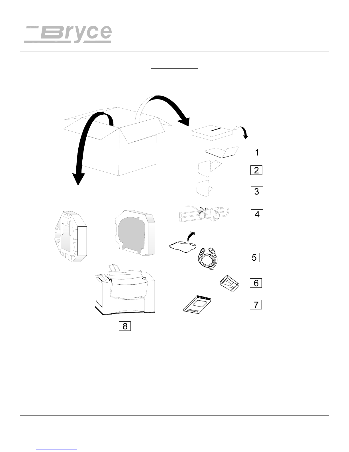
• As you remove the boxes contents, check the pieces against the following list.
;CHECK LIST
__ 1. PAPER CATCH ASSEMBLY __ 7. USERS MANUAL
__ 2. LONG FENCE __ 8. ADDRESS PRINTER
__ 3. SHORT FENCE
__ 4. WIRE FORM
__ 5. LINE CORD
Revision A 9K-L USERS MANUAL Section 1 - 1
P/N 90-00860-001
Page 10

Unpacking
__ 6. INK CARTRIDGE
Revision A 9K-L USERS MANUAL Section 1 - 2
P/N 90-00860-001
Page 11
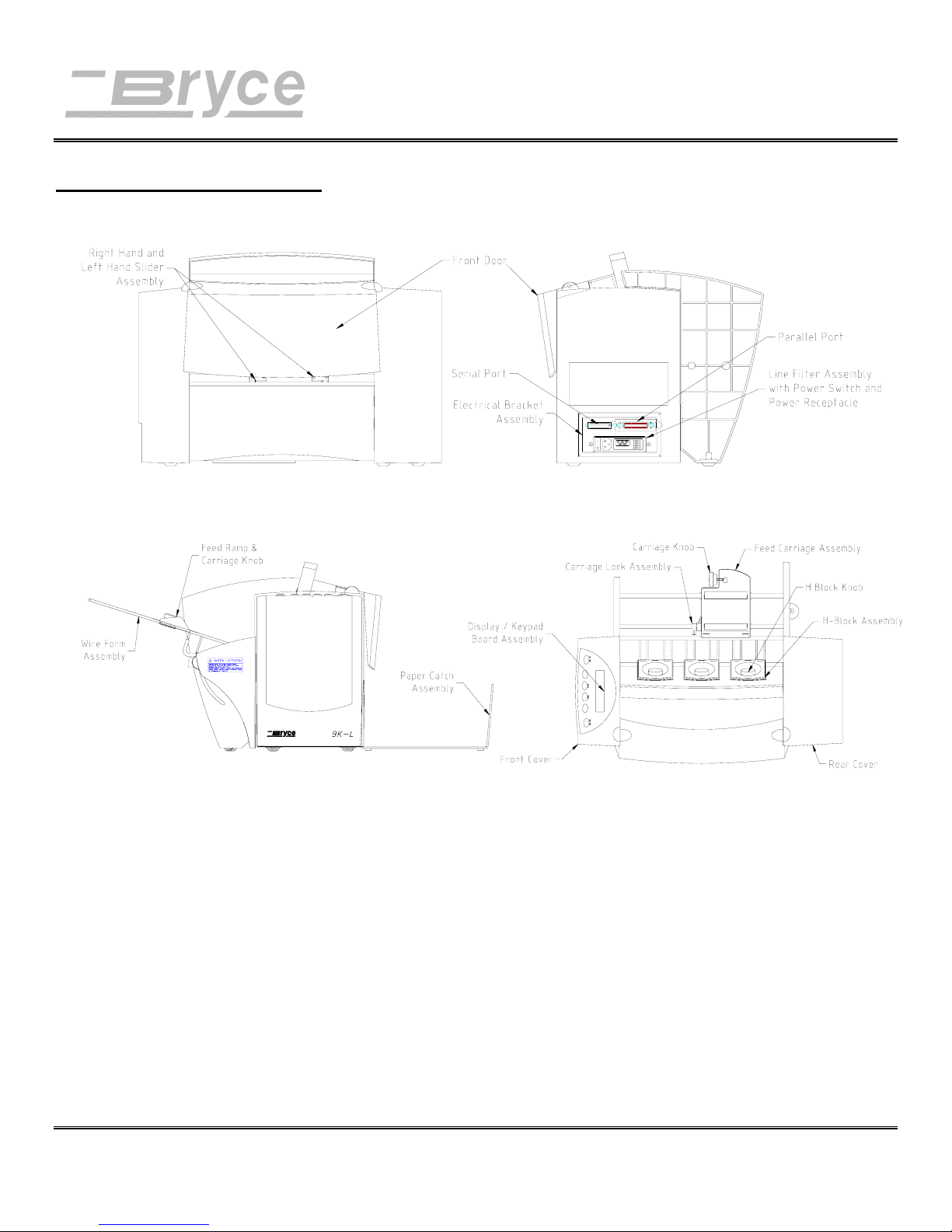
THE PARTS OF THE PRINTER
Parts of the Printer
Input Bin
Media for printing is placed in the input bin. The input bin consists of
The print station processes the data, produces the barcode and prints
Control Panel &
Print Station
Paper Catch
The printed media is placed in the Paper Catch Assembly. Media can
Assembly
Revision A 9K-L USERS MANUAL Section 2 - 1
P/N 90-00860-001
the Wire Form assembly, Feed Carriage Assembly, Sliding Fence (not
shown for ease of illustration) and Separator H-Blocks. These
components adjust to run a variety of media.
out the page. The ability to change the print quality and speed is
handled through the Control Panel and menu options. Use the printers
Adjustment Lever to further enhance the quality of the print.
stack of up to five (5) inches (12.7 cm) in the tray before it has to be
emptied.
Page 12
Assembly of Printer Components
Choosing a
Good
Location for
the Printer
Note: AB switches are
not recommended for
operation with this
printer.
Removing
Protective
Materials
The following environmental considerations must be kept in
mind when selecting a location for the Address Printer. Doing
otherwise may affect the operation and performance of the
Address Printer.
1. Place the printer close enough to the computer for the
parallel or serial cable to reach.
2. Place the printer on a flat, stable surface.
3. Use a grounded, dedicated outlet for the printer only.
Note: Do not use an adapter plug.
4. Avoid locations near direct sunlight, excessive heat,
high humidity, moisture, or dust.
5. Keep the entire system away from large motors or
other appliances that might disturb the power supply or
create potential interference.
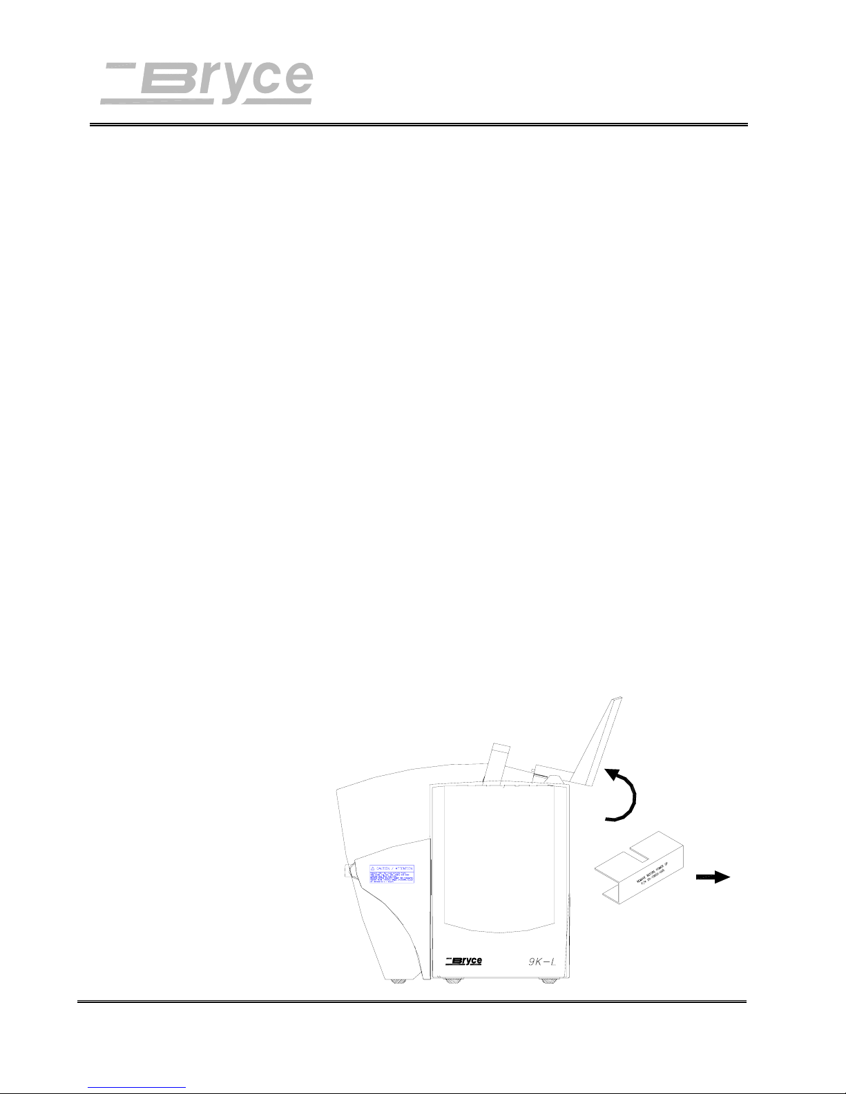
The printer is protected during shipping by a sheet of
corrugated cardboard around the Print Head Holder Assembly.
1. Raise the Front Door to gain access to the interior.
2. Remove the corrugated cardboard. Be careful not to
grab or pull on the ribbon in the back of the Print Head
Holder Assembly.
Revision A 9K-L USERS MANUAL Section 3 -
P/N 90-00860-001
1
Page 13
Installation of
the Wire Form
Assembly
Assembly of Printer Components
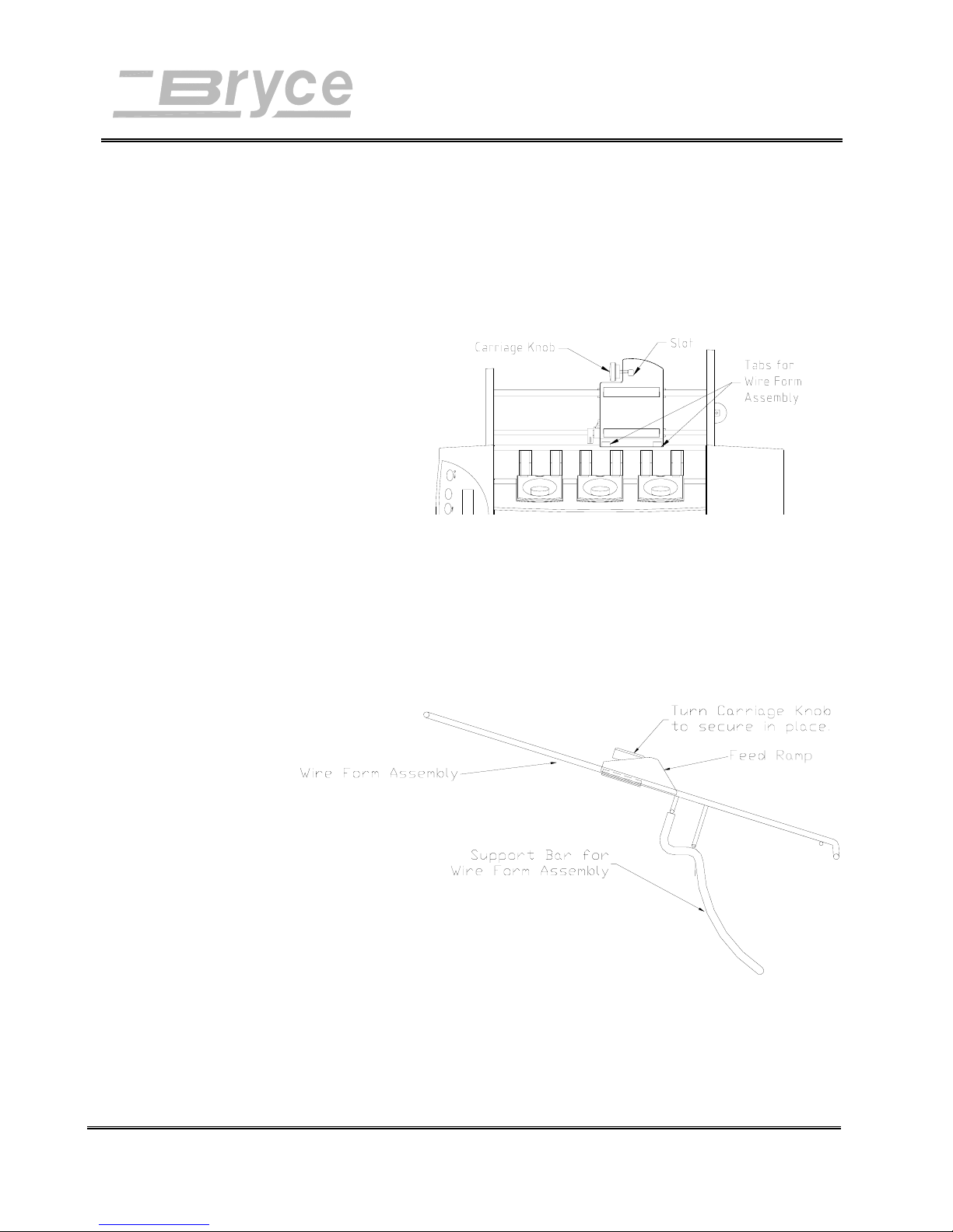
1. Turn the Carriage Knob counter-clockwise on the Feed
Carriage Assembly until the end of the Carriage Knob
is no longer visible in the slot for the supporting bar of
the Wire Form Assembly.
Turn Carriage Knob on the Feed Carriage Assembly to clear the way for the Wire Form Assembly support bar.
2. Move the Feed Ramp to the center of the Wire Form.
Turn the Carriage Knob to secure in place.
Position the Feed Ramp to the center of the Wire Form Assembly and fasten in place.
Revision A 9K-L USERS MANUAL Section 3 -
P/N 90-00860-001
2
Page 14
Assembly of Printer Components
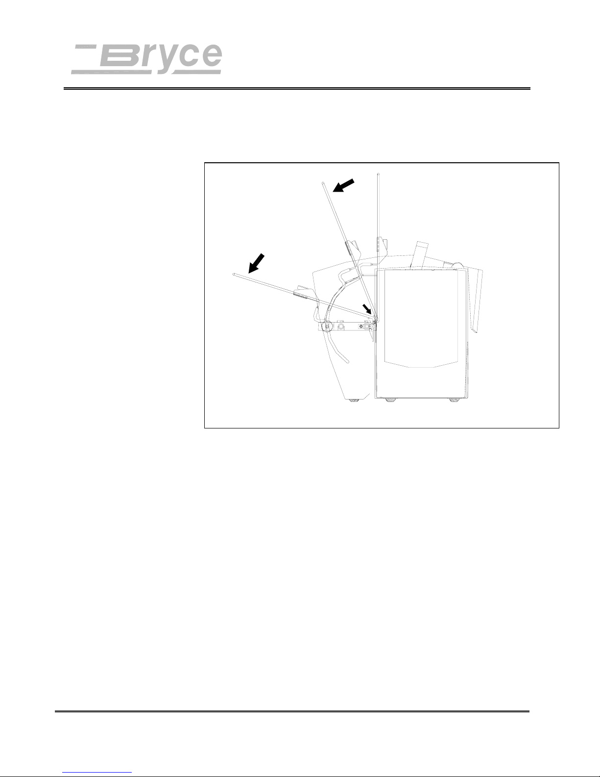
3. Raise the Wire Form to a vertical position.
4. Press Wire Form underneath the two tabs.
Installing the
Sliding Fence
Front Support Plate is not shown for ease of illustration.
5. Rotate top of Wire Form down and insert the curved
supporting bar through the slot in the Feed Carriage
Assembly. Slight force on the Support Bar may be
needed to fit it into the slot.
6. Turn the Carriage Knob on the Feed Carriage
Assembly to hold the Wire Form Assembly in place.
Included in the Accessory Kit is a long and short Sliding
Fence. The fences keep the media together in a stack. Use the
short Sliding Fence for postcards up to media the size of #10
envelopes. Use the Long Sliding Fence for all other sizes.
Revision A 9K-L USERS MANUAL Section 3 -
P/N 90-00860-001
3
Page 15
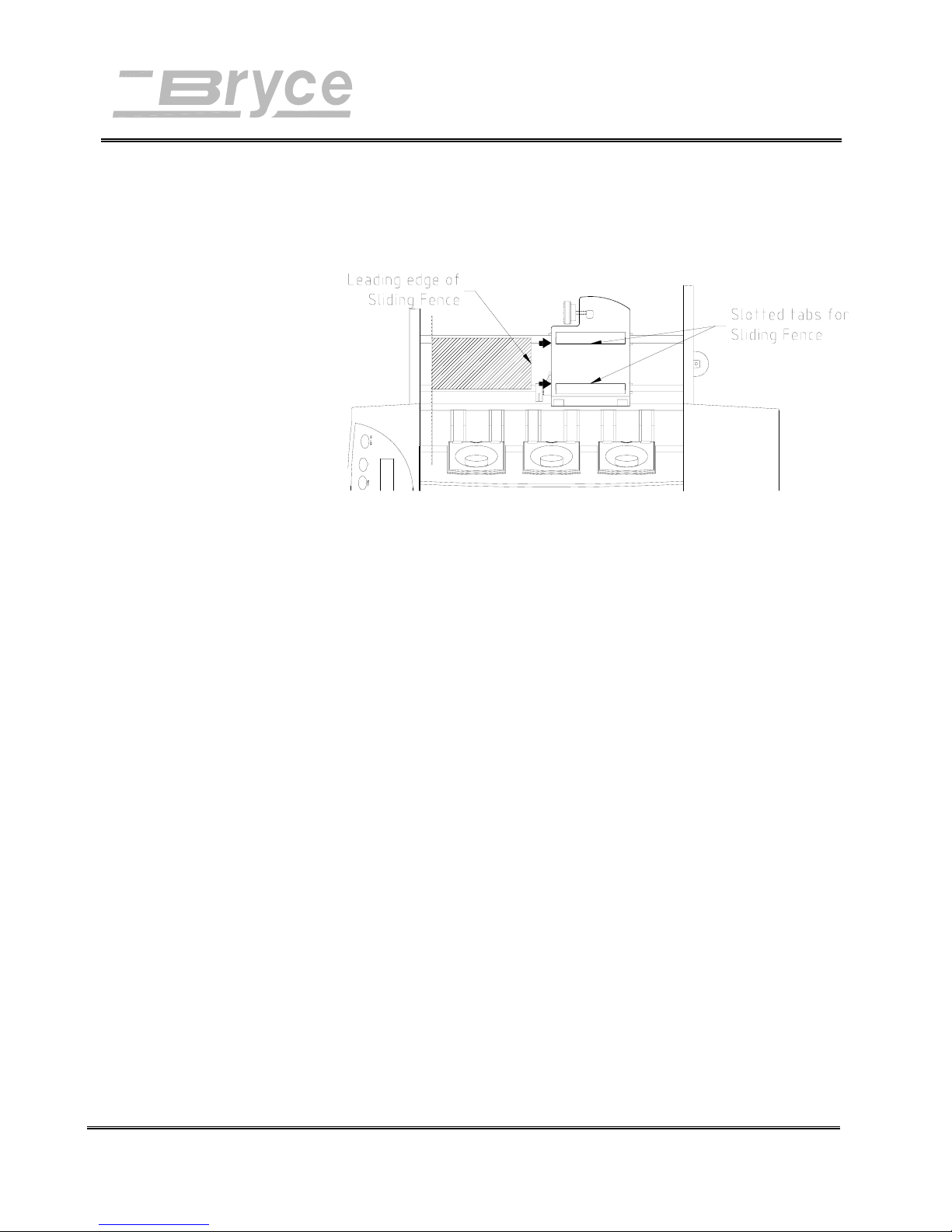
Assembly of Printer Components
1. Locate the two long slotted tabs on the Feed Carriage
Assembly. This is where the Sliding Fence attaches to
the printer.
The drawing is shown without the Wire Form Assembly for ease of illustration.
Connecting
the Printer
Note: AB switches are
not recommended for
operation with this
printer.
2. Slide the rectangular shaped edge of the Sliding Fence
between the two tabs.
Connect the Address Printer to either the serial port or parallel
port of the computer. Initialize the Address Printers
communications port by sending data to either the parallel or
serial port. To change from the serial port to the parallel port
or vice versa the printer must be reinitialized or manually
changed through the Setup Menu. Doing otherwise may affect
the operation and performance of the Address Printer.
To connect printer to the computer do the following steps.
1. Align the male end of the parallel or serial cable
connector. Push the cable connector in.
2. Secure the cable in place. Use the two wire clips
located Parallel connector to snap into the tabs on the
connector. Use the thumb screws on the serial
connector to screw into the hex jack screws on the
Electrical Bracket.
Revision A 9K-L USERS MANUAL Section 3 -
P/N 90-00860-001
4
Page 16
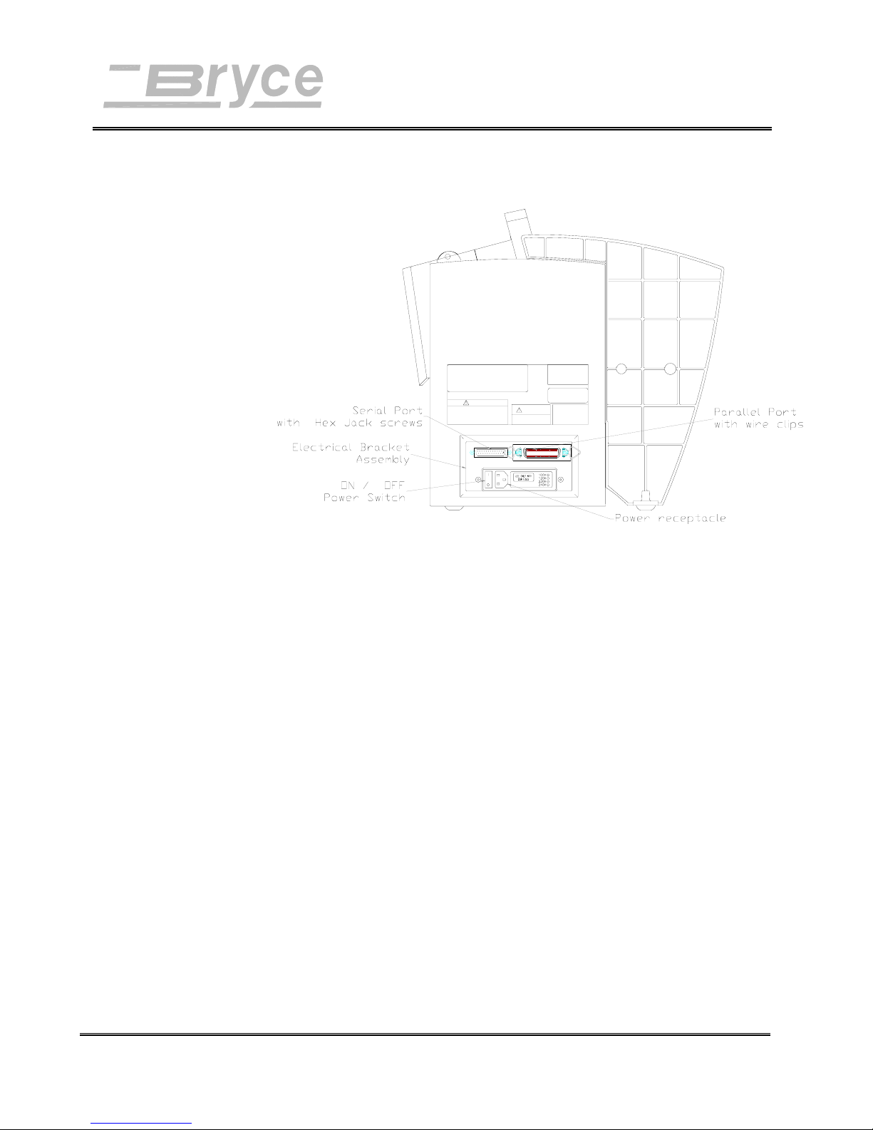
Assembly of Printer Components
3. Align the other end of the cable to the connector on the
computer and push into the port.
Connecting
the Power
Cord
4. Secure the cable in place. Use the thumb screws on the
connector to screw into the hex jack screws on the
computer.
The power cord receptacle is located on the Electrical Bracket
Assembly along with the ON/OFF (I/O) power switch.
Connect the power cord to a grounded outlet.
1. Push the female end of the power cord into the power
receptacle.
2. Plug the other end into a grounded power outlet.
Revision A 9K-L USERS MANUAL Section 3 -
P/N 90-00860-001
5
Page 17
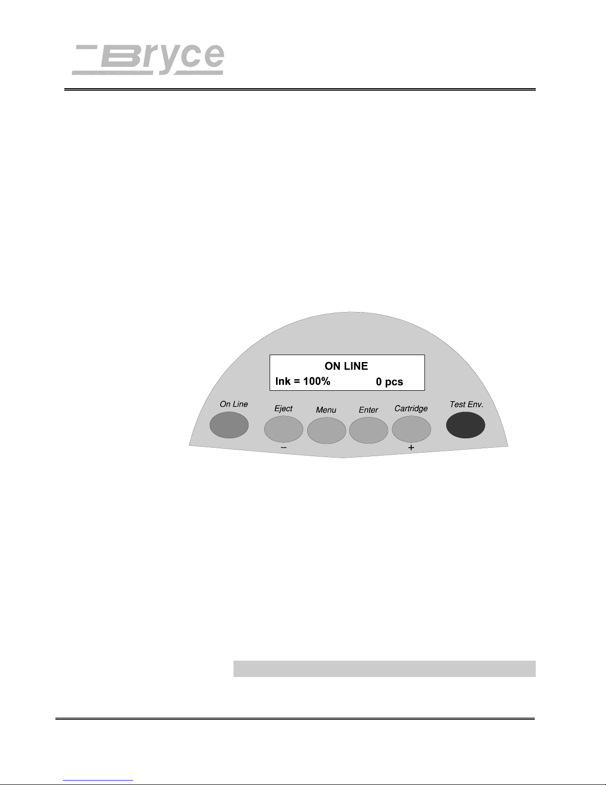
Operating the Printer
Power On
The power cord is plugged in, the printer is connected to the
computer. Now you can turn the power on.
· Press on the printers' ON/OFF (I/O) power
switch. The switch is located on the rear of the
printer next to the line cord receptacle. Press on
the symbol "I" (ON) position. The printer LCD
menu will display the printer is initializing and
will automatically go ON LINE.
The Address Printer uses an Ink Jet Cartridge for printing.
Installing
You must install the Ink Jet Cartridge before you use the
machine. To install the cartridge do the following:
an Ink Jet
Cartridge
Revision A 9K-L USERS MANUAL Section 4 -
P/N 90-00860-001
· Verify the LCD display message on the top line of the
display is either OFF LINE or ON LINE.
· Open the front cover.
· On the top Control Panel, depress Replace Print
Cartridge button (plus button) and the carriage will
travel to the center position and stop. DO NOT
MOVE THE CARRIAGE BY HAND!! Damage may
occur to the carriage.
1
Page 18
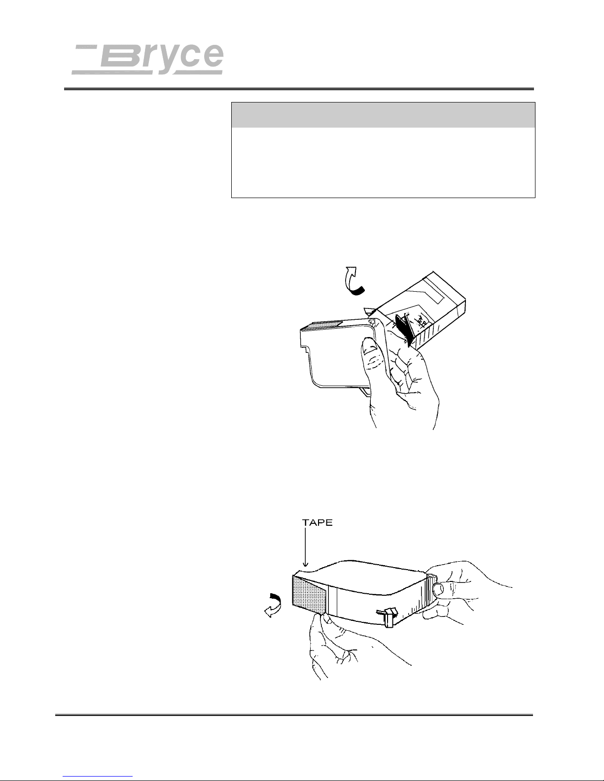
Operating the Printer
CAUTION
The ink in the print cartridge may be harmful if
swallowed. Keep new and used cartridges out of reach of
children. Discard empty print cartridges in the proper
manner.
1. Remove Cartridge from the shipping container by
peeling top cover off. Be careful not to touch the
copper ribbon.
2. Gently remove both pieces of tape covering the ink
nozzles on the print cartridge. Be careful not to touch
the copper nozzles.
Revision A 9K-L USERS MANUAL Section 4 -
P/N 90-00860-001
2
Page 19
Operating the Printer
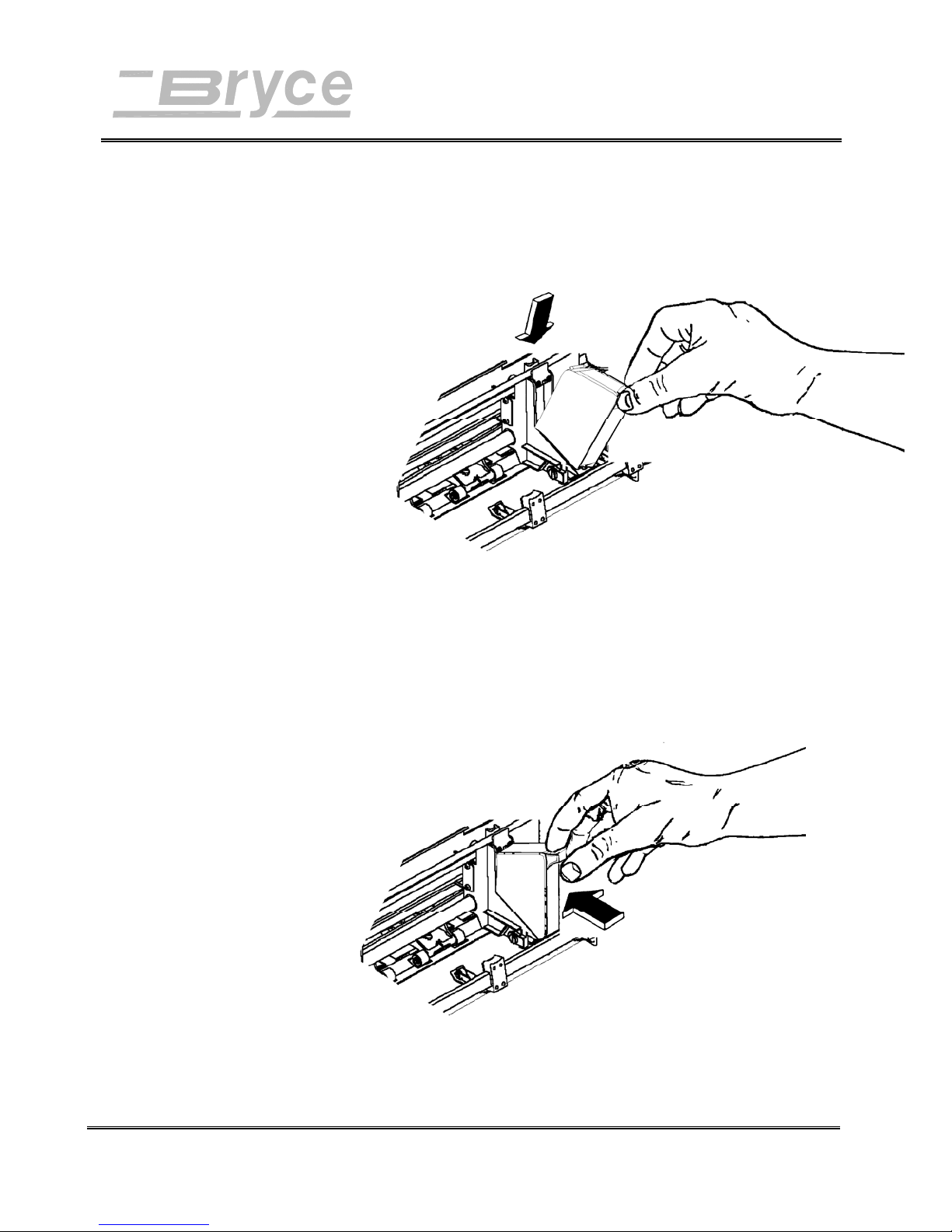
3. Gently insert cartridge down at approximately a 45
degree angle into the cradle of the Print Head Holder
Assembly. Insert with the green arrow on top of the
cartridge pointing toward the input bin.
4. Place forefinger on cradle tab and thumb on top of ink
cartridge and gently squeeze together until the
cartridge snaps into place.
Revision A 9KL USERS MANUAL Section 4 -
P/N 90-00860-001
3
Page 20
Operating the Printer
Removing
an Ink Jet
Cartridge
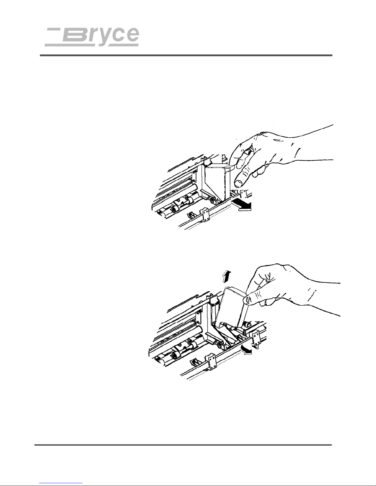
1. Grasp the handle on top. Press down on the cartridge
handle until the cartridge “pops” loose and falls
forward.
2. Lift the print cartridge out of the cradle.
Revision A 9K-L USERS MANUAL Section 4 -
P/N 90-00860-001
4
Page 21
Operating the Printer
Preparing
the Media
Note: Maximum
thickness is 1/9” for
the 9KL.
Recheck that all the necessary components of the printer are
installed.
• Is the Wire Form Assembly installed?
• Is the Sliding Fence installed?
• Is the printer plugged into a power outlet?
• Does the printer have an Ink Jet Cartridge installed?
• Is the printer connected to the computer?
Now that all the parts of the printer are installed the printer
needs to be adjusted to work with the media. To avoid
problems of misfeeding and jams the media must also be made
ready for the printer.
Use the following steps to make the media ready for printing:
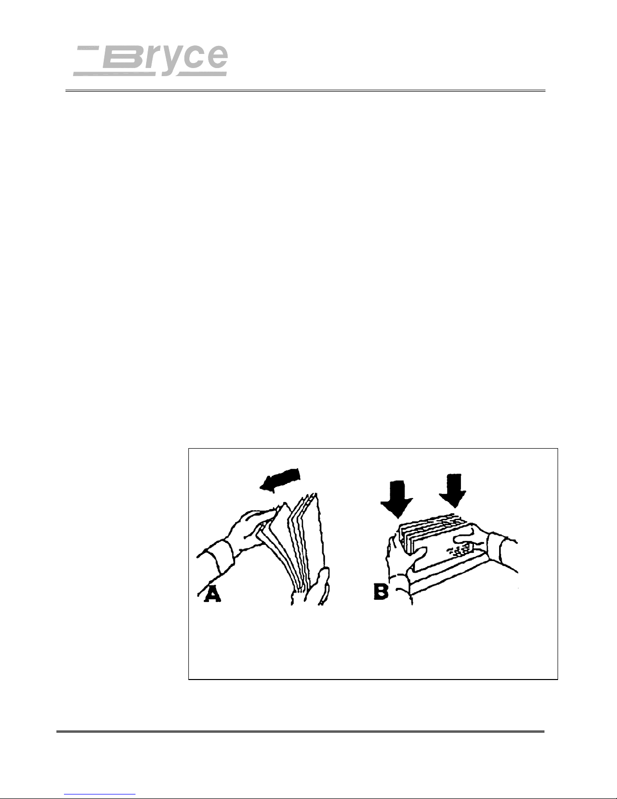
1. Take a manageable pile of media and while holding
them (as shown below in reference A), "fan" all sides
of the media to make sure that each piece of media is
free from one another.
2. Square the pile against the table top, assuring a square
pile on all sides. (Reference B) This will also allow
media to settle toward the bottom of a stuffed envelope
and will increase the feeding capabilities of the printer.
Revision A 9K-L USERS MANUAL Section 4 -
P/N 90-00860-001
Fan All Sides of Media Square Media
5
Page 22

Media
Types
Operating the Printer
The printer is designed to feed and print on a variety of media
with various finishes and coatings. The sharpness of the print
quality will vary with different media types, depending on
how absorbent the media is, as well as other qualities. The
best results can be achieved using white wove bonded stock.
The printing quality will be less sharp on tyvek, recycled and
glossy media.
The types of media the printer is able to use is:
• Envelopes: should be stacked to feed with the
bottom edge first (non flap edge).
• Booklets: should be stacked with the sealed edge
leading or stacked with the sealed edge placed
parallel to the rear wall of the Rear Support Plate
Assembly.
• Catalogs: should be stacked with the sealed edge
leading or stacked with the sealed edge placed
parallel to the rear wall of the Rear Support Plate
Assembly.
• Postcards: must be 3.5” (88.9 mm) x 5” (127 mm)
or larger.
• Self Mailers: may be folded in half or “C” or “Z”.
The media must be tabbed and not exceed the
maximum allowable thickness.
• Paper: may consist of 16 to 80lb of uncoated to
coated stock. The maximum width and height is
specified in Appendix B.
All folded material and catalogs must be tabbed as per postal
regulations.
Revision A 9K-L USERS MANUAL Section 4 -
P/N 90-00860-001
The paper types that can be used are:
• White wove
• Bond Paper
• Recycled Paper
• Coated Paper
• Card Stock
• Brown Kraft
• Manila
6
Page 23
Operating the Printer
w
Setting the
proper feed
gap
Hint: set a smaller
gap between the
separators and feed
roller, by using
standard copy paper
hen using post cards.
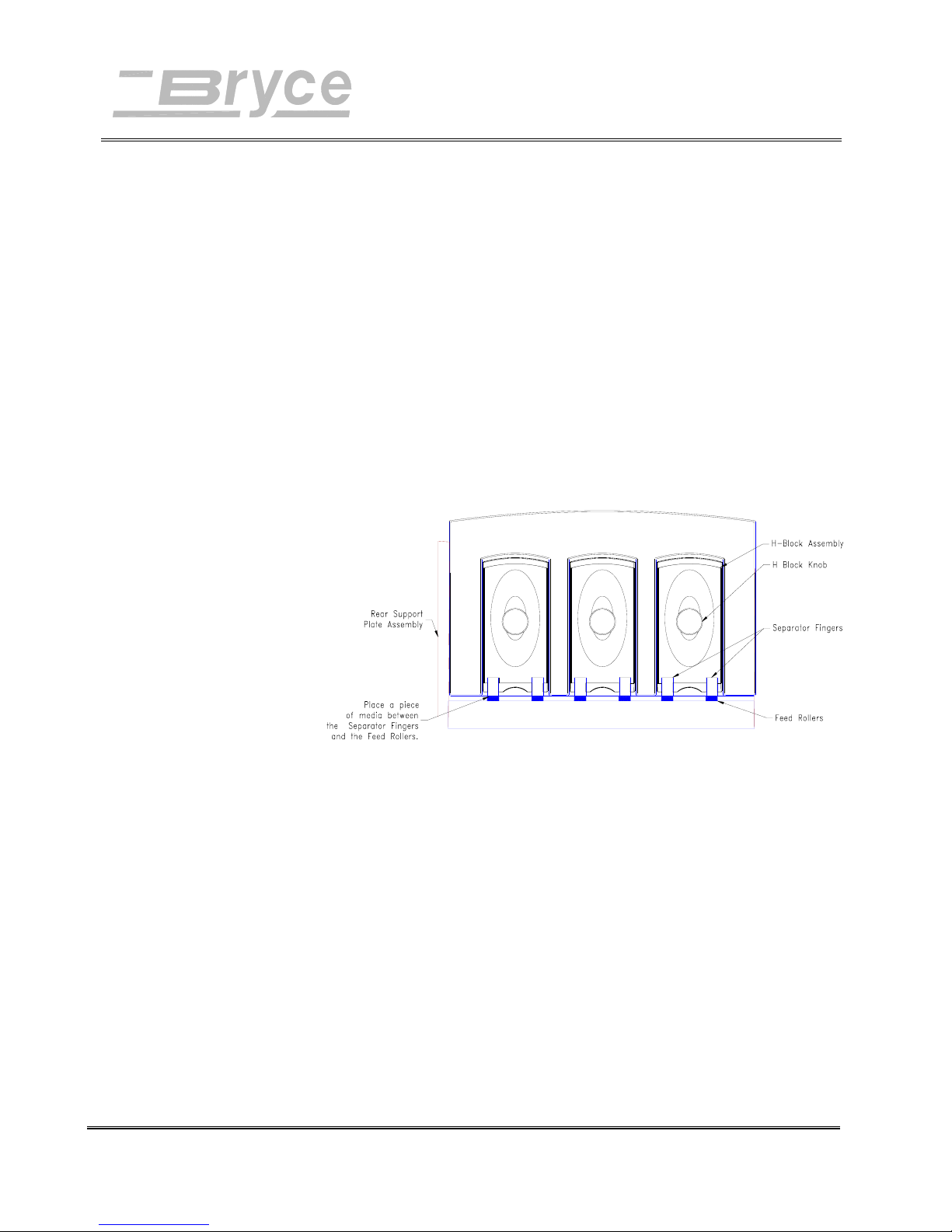
To start a print job the feed gap should be set for each type of
media used in the printer. The feed gap is the spacing between
the feed rollers and the separators. Set the feed gap with a
piece media by following these procedures:
1. Loosen the H Block Knob on the three H-Block
Assemblies.
2. Raise the three H-Block Assemblies up. Tighten the H
Block Knobs to secure H-Block Assemblies in place.
3. Take a piece of the media and place between the Feed
Rollers and the H-Block Assemblies.
4. Square the edge of the media against the wall of the
Rear Support Plate Assembly.
5. Loosen the H Block Knobs and allow the H-Block
Assemblies to drop on top of the media. Keep the HBlock Assembles up that won’t contact the media.
When just one of the separator fingers is in contact
with the media use another piece beneath the other
separator finger and the Feed Roller to set the feed
gap.
6. Tighten H Block Knobs to secure H-Block Assemblies
in this position.
When the feed gap is not set correctly the printer will have
feeding problems. When the gap is too wide double feeding
(feeding two or more pieces at a time) will occur. If the gap is
to small the media will jam beneath the separators. If you
Revision A 9K-L USERS MANUAL Section 4 -
P/N 90-00860-001
7
Page 24

Setup with
#10
Envelopes
Operating the Printer
followed the preceding steps and are experiencing feeding
problem using post cards or stuffed media try the following:
Post cards (.003" thickness) - set a smaller gap between the HBlock Assemblies and the Feed Rollers. Try using a sheet of
copy paper to set the feed gap.
Stuffed Media - set a larger gap between the separator blocks
and the feed roller. Try adding two or three, number ten (# 10)
envelopes, on top of the media before setting the separators.
Perform the preceding steps for setting the feed gap using #10
envelopes. Notice that only two of the H-Block Assemblies
completely rest on the envelope. The third H-Block has one
separator finger on the envelope and one on the feed roller.
1. Take Sliding Fence off and remove out of the way.
2. Fit a second envelope between the other half of the H-
Block Assembly and the Feed Roller.
Wire Form
Adjustments
3. Loosen the H Block Knob to let the H-Block Assembly
fall freely onto the envelope. Verify envelopes are
between all the Separators Fingers and the Feed
Rollers.
4. Lock in place by tightening the H Block Knob.
5. The Input Bin can now be filled with #10 envelopes
for printing. The stack of envelopes should be
"shingled" or layered with the piece on top partially
covering the piece below it like shingles on a roof.
Load into the input bin with flap away from the feed
roller and facing downward. Start with just a few
envelopes to start the stack and get the angled contour
of the bin area, then add several more pieces. Then add
the remainder of the stack.
The Wire Form assembly supports the media stacked in the
input bin area and redistributes the weight of the media to
assist in the feeding of the media. The Wire Form assembly
has three basic adjustments.
Revision A 9K-L USERS MANUAL Section 4 -
P/N 90-00860-001
8
Page 25
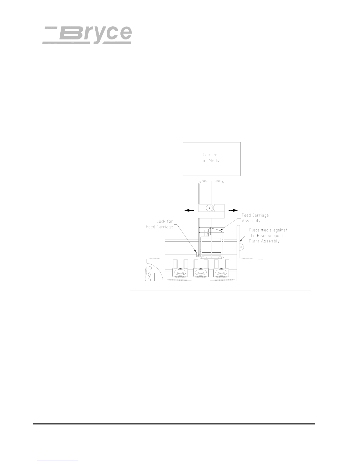
Wire Form
Center
Adjustment
Operating the Printer
• Wire Form Center Adjustment to eliminate
skewing of the media and print.
• Wire Form Height Adjustment to allow the printer
to feed media of varying density. Example: Rigid
media is set low, light weight media is set high.
• Wire Form Ramp Adjustment improves the
feeding of media by distributing the weight of the
media stack onto the feed roller.
Adjust Feed Carriage
The Feed Carriage Assembly needs to be adjusted with the
Wire Form Assembly.
1. Place a piece of the media in the bin area against the
Rear Support Plate Assembly.
2. Unlock Feed Carriage assembly by pushing locking
lever down
3. Slide Feed Carriage Assembly to the center of the
media.
4. Pull lever up to lock Feed Carriage Assembly in place.
Revision A 9K-L USERS MANUAL Section 4 -
P/N 90-00860-001
9
Page 26
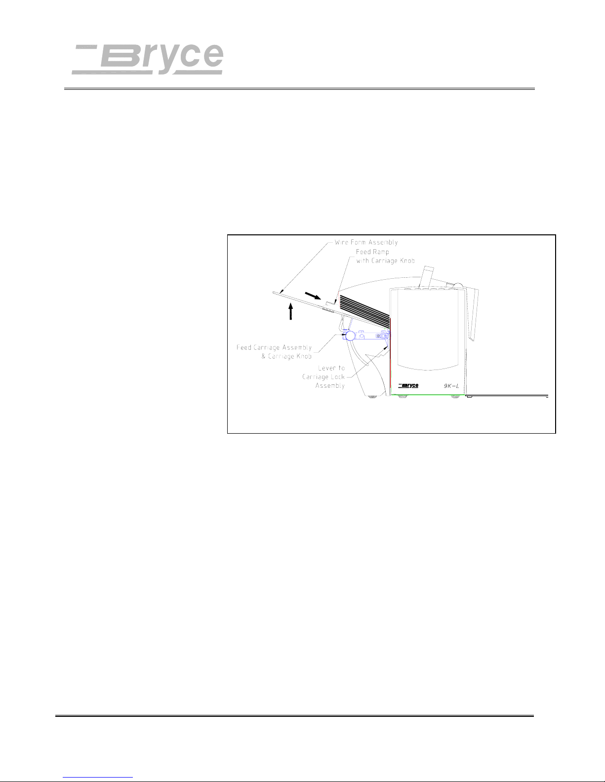
Operating the Printer
Wire Form
Height
Adjustment
The Wire Form Assembly helps the printer feed the media.
Use the following suggestions as a guide for setting the height
of the Wire Form Assembly. When the media is:
• Heavy media- set low
• Light media - set high.
• Rigid media - set low
To adjust the Wire Form Assembly:
1. Loosen the Carriage Knob on the Feed Carriage
Feed Ramp
Adjustment
Adjust Feed Ramp and Wire Form Assembly
Assembly.
2. Move the Wire Form Assembly accordingly.
3. Tighten the Carriage Knob to secure the Wire Form
Assembly in place.
Adjust the Feed Ramp Assembly beneath the rear edge of the
media by:
1. Loosen the Knob on the Feed Ramp Assembly.
2. Lower Feed Ramp beneath the back edge of the media.
Place ramp where the media is halfway up the angled
front edge.
3. Tighten Knob to lock Feed Ramp into position.
Revision A 9K-L USERS MANUAL Section 4 -
P/N 90-00860-001
10
Page 27
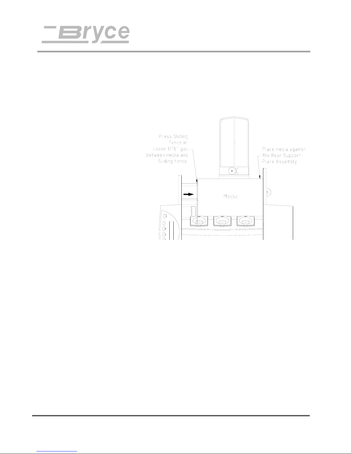
Operating the Printer
Sliding
Fence
Adjustment
Recheck your setup and adjustments:
• Is the feed gap set?
• Is the Wire Form in the center of the media?
• Is the Wire Form at a good height?
• Is the Feed Ramp beneath the edge of the media?
Position the Sliding Fence before stacking the bin area with
media. The fence has to be close enough to the media to keep
it from going in at an angle and loose enough for the media to
drop down to the Feed Rollers. To properly position the fence:
1. Place a handful of the prepared media in the input bin
area.
2. Square the stack against the wall of the Rear Support
Plate Assembly and the H-Block Assemblies.
3. Push the Sliding Fence in near the media. Leave a gap
of 1/16 of a inch (1.6 mm) or the thickness of one or
two #10 envelopes. This size of gap places the fence
close enough to prevent pieces from twisting and
turning as they enter the printer and the fence won’t be
too close to the media to trap and restrain the pieces
between the fence and the wall of the Rear Support
Plate Assembly. This would hinder the media from
being fed into the printer.
Revision A 9K-L USERS MANUAL Section 4 -
P/N 90-00860-001
11
Page 28

Operating the Printer
4. Put the media into the bin. Start with a few pieces to
get the proper contour. The media stack should be
"shingled" when loaded into the input bin with flap
away from the feed roller and facing downward. Add
several more pieces. Keep adding to the stack until the
bin is full of media.
Revision A 9K-L USERS MANUAL Section 4 -
P/N 90-00860-001
12
Page 29
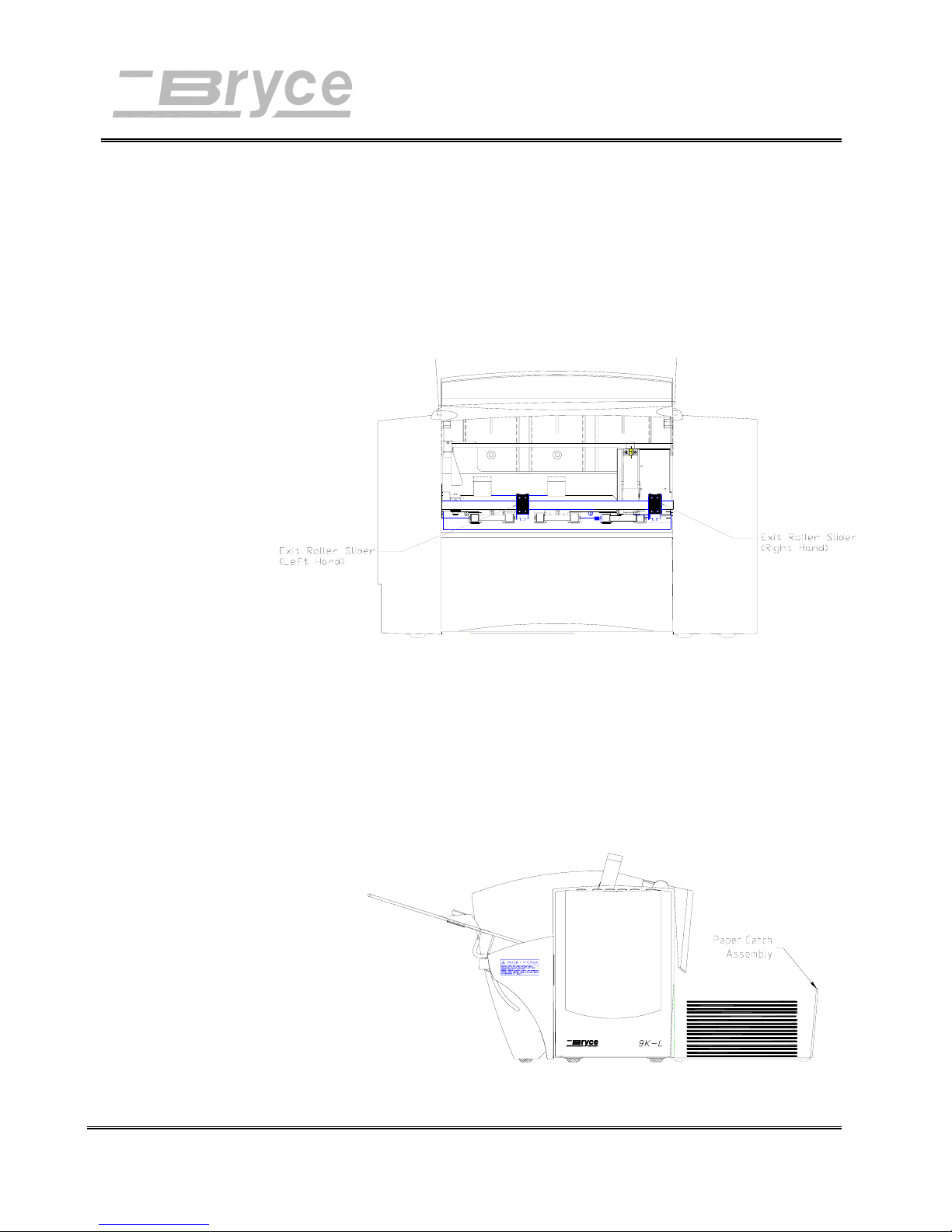
Printer Tips
Adjusting
the Left and
Right Exit
Roller
Slider
Push the Exit Roller Slider left or right to move the slider to a
new position on the shaft. Place the Sliders to 1/4 of an inch
(6.35 mm) from the left and right edges of the media. It is
important to check that the Sliders do not contact any printed
information on the media. If the rollers do roll over any
printed areas they will act as a brush with paint and smear the
print. Move the rollers in more or out more toward the nearest
clear zone (non printing area of the media).
Output
Stack
Height
The Paper Catch Assembly will stack up to five (5) inches
(12.7 cm) of media before it is necessary to remove the stack
from the paper catch assembly. If the paper catch is not
emptied regularly then there is the potential for the stack to be
out of sequence, particularly when the printer is printing
toward the top of the media.
Revision A 9K-L USERS MANUAL Section 5 - 1
P/N 90-00860-001
Page 30
Printer Tips
Adjustment
Lever Fine
Tuning
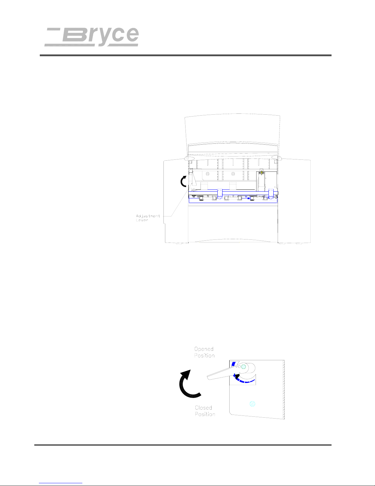
The Adjustment Lever changes the distance of the ink jet
cartridge from the media. This gives the printer the ability to
adapt to different types of media. Proper use of the lever
results in clean crisp print. Perform the following steps to get
best quality possible with the printer:
Note: If the print
smudges the ink
cartridge is touching
the media. Raise up
the Adjustment Lever
until it stops.
1. Load the media that is going to be used for a job.
2. Raise the Adjustment Lever to the fully opened
position. Reference the Figure below.
3. Press the Test Env. button down. The printer feeds
and prints a test piece.
1. If the print is indistinct, hazy or too light, lower the
lever. Keep lowering the lever and pressing the Test
Env. button until the best print quality is found.
Revision A 9K-L USERS MANUAL Section 5 - 2
P/N 90-00860-001
Page 31
Control Panel and
LCD Display
KEYPAD
Printer Menu System
DEFINITIONS
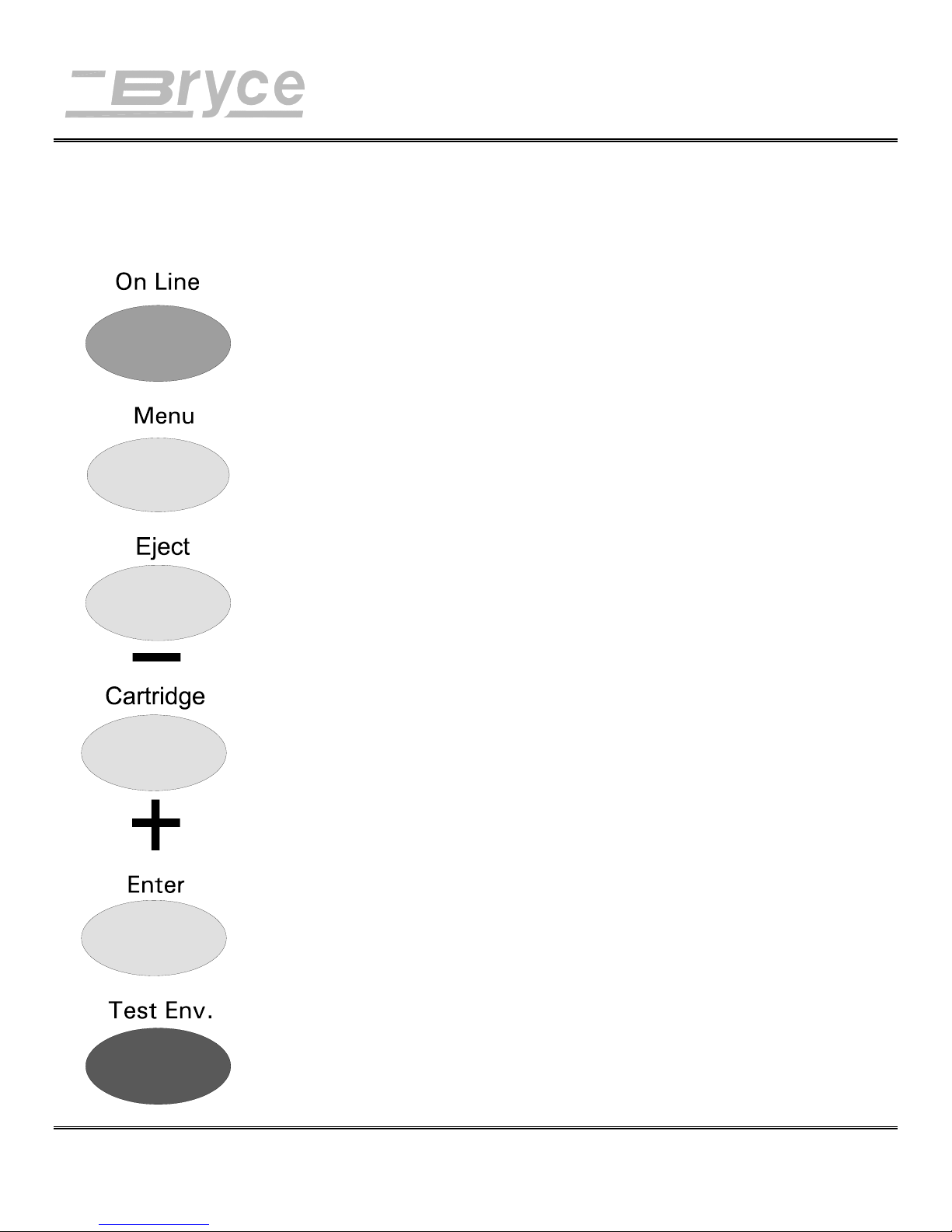
The printer buttons on the control panel perform the following functions:
On Line button Use this button to toggle the printer between ON
LINE or OFF LINE.
Menu button: Press this button to go into the menus or to exit from
the menus.
Eject (Minus) button Press this button, while in a menu, to scroll the menu
features from bottom to top.
When the printer is OFF LINE or ON LINE, press this
button to eject the piece of media out from under the
exit rollers.
Cartridge (Plus) button: Press this button, while in a menu, to scroll the
menu features from top to bottom.
When the printer is OFF LINE or ON LINE,
press this button to make the print head holder travel to
the center position of the floor assembly for easy
access when removing or installing a print cartridge.
Press again to return the print head holder.
Enter button: Press this button, while in a menu, to select a menu
feature.
Test Env. button: When the printer is OFF LINE, press this button to
Revision A 9K-L USERS MANUAL Section 6 - 1
P/N 90-00860-001
print an internal test address message.
Page 32

Printer Menu System
HOW TO USE THE MENUS
Conventions
used in the
Printer Menu
System section.
Accessing
the Menus
Bold is used for the Menu, On Line, Enter, + (Plus), (Minus) buttons when they must be pressed to program or
operate the printer.
ALL CAPITAL LETTERS are used to highlight words that
appear on the LCD display, and menu options: i.e. MAIN
MENU, SETUP MENU.
Italics are used to define the function of the printers menu
option.
Capitalized are used to denote the name of the menu option:
i.e. Main Menu, Setup Menu.
The printer has two menu directories to program the printer.
These menus are displayed on the LCD panel located on top
of the printer. The two menus available are the Main Menu
and the Setup Menu. Some of the menu options contain
several layers of sub-directories of menu options. To access
the printers menus the LCD display must show OFF LINE.
The following steps outline how to access the two menu
directories.
• Press the On Line button until the LCD display shows
“OFF LINE”. Pressing the On Line button on the
control panel will toggle the printer from ON LINE to
OFF LINE and vice versa.
• To access the Main Menu depress the Menu button.
MAIN MENU will be shown on the LCD display.
• To access the Setup Menu depress the Menu button
for two (2) seconds, until SETUP MENU is shown on
the LCD display.
• Press the + (Plus) or - (Minus) button to scroll
through the options available in the Main Menu or
the Setup Menu.
Revision A 9K-L USERS MANUAL Section 6 -
P/N 90-00860-001
2
Page 33

Printer Menu System
• Press the Enter button to choose the displayed
option from the Main Menu or Setup Menu
options.
• Press the Menu button several times to back out of the
Main Menu or Setup Menu until the printer displays
OFF LINE.
• Press the On Line button; now the printer displays ON
LINE and is ready for use.
Revision A 9K-L USERS MANUAL Section 6 -
P/N 90-00860-001
3
Page 34

Printer Menu System
MAIN MENU
Using the
Main Menu
Use the Main Menu level to choose the print specifications
and page layout for your media. Select the desired option
when it appears on the second line of the LCD. Note: An
Asterisk (*) displayed before the menu option is an indicator
of the current menu option setting. Selecting another menu
option will install the asterisk before the option. Upon receipt
of the printer from the factory the asterisk is typically the
default setting.
These options are covered in the following pages.
1. ADDRESS LAYOUT
2. PRINT QUALITY
3. FONT
4. BARCODE
5. ADDRESS RECOVERY
6. CLEAR COUNTER
7. JOB SETTINGS
1. ADDRESS
LAYOUT
Revision A 9K-L USERS MANUAL Section 6 -
P/N 90-00860-001
Use this option to change the page layout for your mail piece.
Use the following steps to access the Address Layout submenus.
• Press the + or - buttons to scroll through the Main
Menu options until the 1. ADDRESS LAYOUT
option is displayed on the LCD panel.
• Press the Enter button to select this option.
• Press the + or - buttons to scroll through the 1.
ADDRESS LAYOUT options.
A. DISTANCE TO RIGHT
B. DISTANCE TO BOTTOM
C. LINE SPACING
D. ORIENTATION
4
Page 35
Printer Menu System
A. Distance
to Right
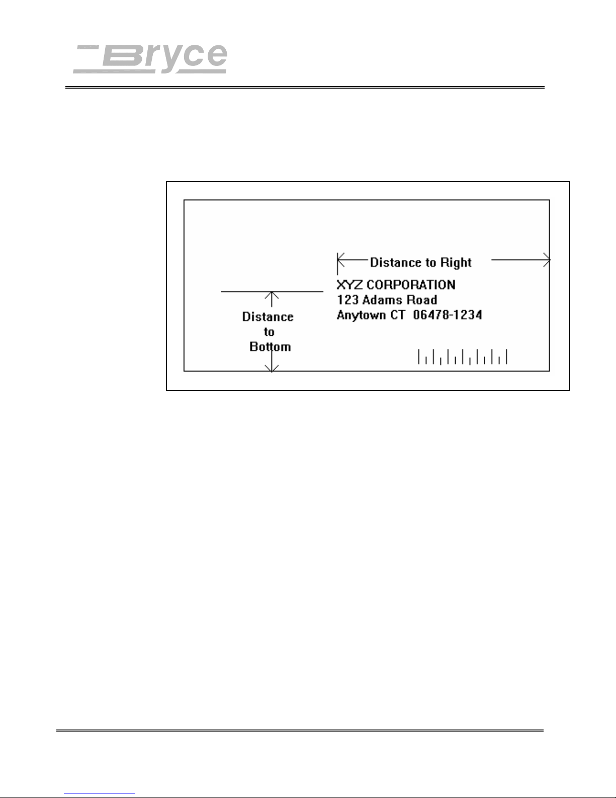
Distance to Right is the distance measured from the
right edge of the media to the first printable character.
See example.
Example:
B. Distance
to Bottom
Use the following steps to change the position of the
record on the media.
• Press the Enter button to select this option.
• Press the + ( MORE ) or - ( LESS ) buttons to
increase / decrease the distance to the right edge of
the media.
• Press the Enter button to select the desired
measurement.
• Press the Menu button several times to back out of
the Main Menu until the printer displays OFF
LINE.
• Press the On Line button; now the printer is ready
for use.
The Distance to Bottom is the distance between the
bottom edge of the media and the base of the first line
of the address. Minimum distance between the bottom
of the last line of the address and the bottom edge of
the media is 5/8 inches (10.58mm). If less than 5/8
Revision A 9K-L USERS MANUAL Section 6 -
P/N 90-00860-001
5
Page 36

Printer Menu System
inches (10.58mm), the lower right barcode will not be
printed.
Use the following steps to change the position of the
record on the media.
• Press the Enter button to select this option.
• Press the + ( MORE ) or - ( LESS ) buttons to
increase / decrease the distance from the bottom.
• Press the Enter button to select the desired
measurement.
• Press the Menu button several times to back out of
the Main Menu until the printer displays OFF
LINE.
• Press the On Line button, now the printer is ready
for use.
C. Line
Spacing
This sets the distance between lines of text. It is
measured as the number of lines per inch of text. Note:
Whenever changing the point size of the font, use the
automatic line spacing option. The printer will
automatically select the correct setting for the
increased or decreased font size of the characters being
printed.
Use the following steps to change the spacing between
line of text.
• Press the Enter button to select this option.
• Press the + or - buttons to scroll through the line
spacing options:
A) AUTOMATIC
B) 3 LINES / INCH
C) 4 LINES / INCH
D) 6 LINES / INCH
E) 8 LINES / INCH
Revision A 9K-L USERS MANUAL Section 6 -
P/N 90-00860-001
• Press the Enter button to select the desired option.
6
Page 37

Printer Menu System
• Press the Menu button several times to back out of
the Main Menu until the printer displays OFF
LINE.
• Press the On Line button; now the printer is ready
for use.
D.
Orientation
a) Normal
This changes the direction that the print appears on the
media.
Use the following steps to select the orientation submenus.
• Press the Enter button to select this option.
• Press the + or - buttons to scroll through the
orientation options:
A) NORMAL
B) INVERT
When the Orientation is set to Normal the
leading edge of the media is assumed to be the
bottom with the right edge running against the
side of the printer. These assumptions are
necessary for a barcode to be printed on the
lower right edge of the media/envelopes.
Use the following steps to set the direction of
print on the media to Normal.
b) Invert
Revision A 9K-L USERS MANUAL Section 6 -
P/N 90-00860-001
• Press the Enter button to select this option.
• Press the Menu button several times to
back out of the Main Menu until the printer
displays OFF LINE.
• Press the On Line button; now the printer
is ready for use.
Setting the Orientation to Invert notifies the
printer that the top of the media now enters and
exits first, and that the media left edge will run
along the side of the printer. Selecting this
option automatically alters the printer’s 1.
ADDRESS LAYOUT options (A. Distance to
Left, B. Distance to Top). Note: Whenever the
Invert option is selected the lower right barcode
7
Page 38

Printer Menu System
feature is disabled. The reason for this, is that
the edge of the lower right hand side of the
media is unknown.
Use the following steps to set the direction of
print on the media to Invert.
• Press the Enter button to select this option.
• Press the Menu button several times to
back out of the Main Menu until the printer
displays OFF LINE.
• Press the On Line button; now the printer
is ready for use.
E.
ORIENTATION
CNTRL.
(CONTROL)
a) Automatic
This option allows the printer to ignore the orientation
commands sent by the computer.
Use the following steps to select the orientation control
sub-menus.
• Press the Enter button to select this option.
• Press the + or - buttons to scroll through the
orientation options:
A) AUTOMATIC
B) MANUAL
When the Orientation Control is set to
Automatic the printer acknowledges the
orientation commands sent from the computer.
Use the following steps to set the direction of
print on the media to Automatic.
• Press the Enter button to select this option.
• Press the Menu button several times to
back out of the Main Menu until the printer
displays OFF LINE.
b) Manual
Revision A 9K-L USERS MANUAL Section 6 -
P/N 90-00860-001
• Press the On Line button; now the printer
is ready for use.
Setting the Orientation to Manual notifies the
printer to use the menu settings for orientation.
8
Page 39

Printer Menu System
Use the following steps to set the orientation
control of the printer to Manual.
• Press the Enter button to select this option.
• Press the Menu button several times to
back out of the Main Menu until the printer
displays OFF LINE.
• Press the On Line button; now the printer
is ready for use.
2. PRINT QUALITY
A.
Executive
This option changes the speed of the printer and the density of
the characters printed on the media.
Use the following steps to select the Print Quality sub-menus.
• Press the + or - buttons to scroll through the Main
Menu options until the 2. PRINT QUALITY option is
displayed on the LCD panel.
• Press the Enter button to select this option.
• Press the + or - buttons to scroll through the 2. PRINT
QUALITY options.
A. EXECUTIVE
B. LETTER
C. DRAFT
Executive quality is used for documents that require a
professional appearance. This is the darkest of the
three print qualities, the slowest print speed and uses
the most ink.
Revision A 9K-L USERS MANUAL Section 6 -
P/N 90-00860-001
Use the following steps to change the quality of print
to black.
• Press the Enter button to select this option.
9
Page 40

Printer Menu System
• Press the Menu button several times to back out of
the Main Menu until the printer displays OFF
LINE.
• Press the On Line button; now the printer is ready
for use.
B. Letter
C. Draft
Letter quality is used for documents that require a
finished, polished appearance.
Use the following steps to change the quality of print
to dark gray.
• Press the Enter button to select this option.
• Press the Menu button several times to back out of
the Main Menu until the printer displays OFF
LINE.
• Press the On Line button; now the printer is ready
for use.
Draft quality prints documents the fastest and saves
ink. This option offers the highest print speed and
prints the lightest of the three print qualities. Use the
following steps to change the quality of print to light
gray.
• Press the Enter button to select this option.
• Press the Menu button several times to back out of
the Main Menu until the printer displays OFF
LINE.
3. FONT
Revision A 9K-L USERS MANUAL Section 6 -
P/N 90-00860-001
• Press the On Line button; now the printer is ready
for use.
Use this option to alter the fonts characteristics: typeface,
point size, spacing, stroke weight, and style.
Use the following steps to select the Font sub-menus.
• Press the + or - buttons to scroll through the Main
Menu options until the 3. FONT option is displayed on
the LCD panel.
• Press the Enter button to select this option.
10
Page 41

Printer Menu System
• Press the + or - buttons to scroll through the 3. FONT
options.
Note: When A. NAME is shown on the display as a
Menu option, press the Test button and a complete
listing of the available fonts will be printed out in their
typeface.
A. NAME
B. SIZE
C. WIDTH
D. BOLD
E. ITALIC
F. OUTLINE
A. Name
There are twelve internal distinct typefaces available
with the printer. A typeface is the unique design of
finishing strokes and serifs of a character set.
Note: Press the Test button when a font name is
displayed on the LCD. A list of the character set is
printed in the fonts typeface. Use these same steps
to print a character set from a font card.
Many optional fonts are available by installing an
optional font card. The Font card must be installed
(Font label facing the front of the printer). Turn the
printer power off for 10 seconds or more. Insert the
font card, then power on the printer to use the external
font card.
Use the following steps to change the typeface of the
font.
• Press the Enter button to select this option.
Revision A 9K-L USERS MANUAL Section 6 -
P/N 90-00860-001
11
Page 42

Printer Menu System
• Press the + or - buttons to scroll through the A.
Name options until the desired selection is
displayed on the LCD panel.
a) COURIER
b) SAN SERIF
c) ROMAN
d) BAXTER
e) DINGBAT
f) HANCOCK
g) MARINA
h) QUINCY
i) SILICON
j) SPRINGER
k) STENCIL
B. Size
l) WINDMILL
• Press the Enter button to select the desired option.
• Press the Menu button several times to back out of
the Main Menu until the printer displays OFF
LINE.
• Press the On Line button; now the printer is ready
for use.
The font Size (internal or external) can be set from 4 to
30 point. Font sizes up to 30 Point can be downloaded
from Microsoft Windows™ to the 9KL Address
Printer (one inch equals 72 point). The point size of
this text is 12 point.
Use the following steps to change the size of the font.
• Press the Enter button to select this option.
• Press the + or - button to select + LARGER
(increase the point size increases the character
height) or - SMALLER point size.
Revision A 9K-L USERS MANUAL Section 6 -
P/N 90-00860-001
• Press the Enter button to select the desired option.
12
Page 43

Printer Menu System
• Press the Menu button several times to back out of
the Main Menu until the printer displays OFF
LINE.
• Press the On Line button; now the printer is ready
for use.
Example:
This is a test message in 8 point.
This is a test message in 12 point.
This is a Roman Text in 20
point.
Courier Text
in 30 point.
C. Width
Use this option to change the width of spaces between
characters and the width of characters. Normal (100%)
print width is the standard width of characters and
spaces between characters. Settings of Thin (75%) and
Condensed (50%) will decrease the spacing between
characters and decrease the width of characters. The
settings of Wide (125%) and Expanded (150%)
increase the width of characters and spaces.
Use the following steps to change the spacing and
width of the font.
• Press the Enter button to select this option.
• Press the + or - buttons to scroll through the C.
Width options.
a) CONDENSED (50%)
b) THIN (75%)
c) NORMAL (100%)
d) WIDE (125%)
e) EXPANDED (150%)
• Press the Enter button to select the desired option.
Revision A 9K-L USERS MANUAL Section 6 -
P/N 90-00860-001
13
Page 44

Printer Menu System
• Press the Menu button several times to back out of
the Main Menu until the printer displays OFF
LINE.
• Press the On Line button; now the printer is ready
for use.
D. Bold
E. Italic
This increases the character stroke weight (thickness of
print). Bold is used to emphasize or highlight text in
an address.
Use the following steps to bold the font.
• Press the Enter button to select this option.
• Press the + or - buttons to scroll through the D.
Bold options: ON or OFF.
• Press the Enter button to select the desired option.
• Press the Menu button several times to back out of
the Main Menu until the printer displays OFF
LINE.
• Press the On Line button; now the printer is ready
for use.
This refers to the oblique shape of a character and is
used to emphasize text in an address.
Use the following steps to change the font to italic.
• Press the Enter button to select this option.
• Press the + or - buttons to scroll through the E.
Italic options: ON or OFF.
• Press the Enter button to select the desired option.
• Press the Menu button several times to back out of
the Main Menu until the printer displays OFF
LINE.
• Press the On Line button; now the printer is ready
for use.
Revision A 9K-L USERS MANUAL Section 6 -
P/N 90-00860-001
14
Page 45

Printer Menu System
F. Outline
4. BARCODE
Use this option to print only the outline or the edge of
the fonts shape. All the records printed using Outline
will appear as hollow text. The Outline option
will emphasize text in an address.
Use the following steps to print the font outline.
• Press the Enter button to select this option.
• Press the + or - buttons to scroll through the F.
Outline options: ON or OFF.
• Press the Enter button to select the desired option.
• Press the Menu button several times to back out of
the Main Menu until the printer displays OFF
LINE.
• Press the On Line button; now the printer is ready
for use.
Use this option to position the barcode or to choose not to
include a barcode on the piece of media.
A. Location
• Press the + or - buttons to scroll through the Main
Menu options until the 4. BARCODE option is
displayed on the LCD panel.
• Press the Enter button to select this option.
• Press the + or - buttons to scroll through the options.
A. LOCATION
B. 5 DIGIT ON/OFF
Use this option to disable printing the barcode or to
select where to print the US Postal Service Postnet
Barcode.
• Press the Enter button to select this option.
Revision A 9K-L USERS MANUAL Section 6 -
P/N 90-00860-001
15
Page 46

Printer Menu System
• Press the + or - buttons to scroll through the
Location options.
a) LOWER RIGHT CORNER
b) ABOVE ADDRESS
c) BELOW ADDRESS
d) OFF
a) Lower Right
Corner
b) Above Address
Use this option to print the barcode on the
lower right edge of the media. Note: This
option is disabled when the selected
Orientation is Invert.
• Press the Enter button to select this
option.
• Press the Menu button several times to
back out of the Main Menu until the
printer displays OFF LINE.
• Press the On Line button; now the
printer is ready for use.
Use this option to print the barcode in the
address block above the first line of the address
on the media.
• Press the Enter button to select this
option.
• Press the Menu button several times to
back out of the Main Menu until the
printer displays OFF LINE.
c) Below Address
Revision A 9K-L USERS MANUAL Section 6 -
P/N 90-00860-001
• Press the On Line button; now the
printer is ready for use.
Use this option to print the barcode below the
last line of the address in the address block on
the media.
• Press the Enter button to select this
option.
• Press the Menu button several times to
back out of the Main Menu until the
printer displays OFF LINE.
16
Page 47

Printer Menu System
• Press the On Line button; now the
printer is ready for use.
d) Off
B. 5 Digit
On / Off
Use this option to stop the printing of a
Delivery Point Barcode (DPBC) on the media.
• Press the Enter button to select this
option.
• Press the Menu button several times to
back out of the Main Menu until the
printer displays OFF LINE.
• Press the On Line button; now the
printer is ready for use.
Use this option to print a 5 Digit barcode for a five
digit zip code. Note: Only a 5 Digit barcode is printed
for a five digit zip code when enabled. A Delivery
Point Bar Code cannot be generated from a five digit
zip code.
• Press the Enter button to select this option.
• Press the + or - buttons to scroll through the 5
Digit On / Off options of ON or OFF (default
setting is OFF). If enabled (On) a 5 digit zip code
will be printed.
• Press the Enter button to select the desired option.
• Press the Menu button several times to back out of
the Main Menu until the printer displays OFF
LINE.
• Press the On Line button; now the printer is ready
for use.
If something goes wrong while printing use this option to
5. ADDRESS
RECOVERY
direct the printer to re-print up to 20 of the last records or to
clear the printers memory of all records.
• Press the + or - buttons to scroll through the Main
Menu options until the 5. ADDRESS RECOVERY
option is displayed on the LCD panel.
• Press the Enter button to select this option.
Revision A 9K-L USERS MANUAL Section 6 -
P/N 90-00860-001
17
Page 48

Printer Menu System
• Press the + or - buttons to scroll through the Address
Recovery options.
A. GET ADDRESSES
B. CLEAR MEMORY
A. Get
Addresses
Use this option to retrieve up to 20 records from the
data buffer.
• Press the Enter button to select this option.
• The display will say 00: and show the first 16
characters of the last address printed. Press the
Enter button to select the record and advance the
display to the next to last record. Keep on pressing
the Enter button to continue advancing back
through the records and to select the displayed
records. NONE TO RECOVER is displayed when
no more records are able to be retrieved. If NONE
TO RECOVER is first displayed then the data
buffer is empty.
• Press the Menu button several times to back out of
the Main Menu until the printer displays OFF
LINE.
• Press the On Line button; now the printer is ready
for use. Note: The recovered records will print
once the printer is ON LINE.
B. Clear
Memory
Revision A 9K-L USERS MANUAL Section 6 -
P/N 90-00860-001
Use this option to remove any data left in the data
buffer.
• Press the Enter button to select this option.
• Press the + (YES) button to clear the printers
memory or press the - (NO) button if you do not
wish to clear the address data from the memory.
• Press the Menu button several times to back out of
the Main Menu until the printer displays OFF
LINE.
• Press the On Line button; now the printer is ready
for use.
18
Page 49

Printer Menu System
Use this option to clear the piece (batch) counter.
6. CLEAR
COUNTER
7. JOB SETTINGS
• Press the + or - buttons to scroll through the Main
Menu options until the 6. CLEAR COUNTER option
is displayed on the LCD panel.
• Press the Enter button to select this option.
• Press the + (YES) button to reset the counter to zero
or press the - (NO) button to leave the current number
of pieces printed (PCS) on the LCD display.
• Press the Menu button several times to back out of the
Main Menu until the printer displays OFF LINE.
• Press the On Line button; now the printer is ready for
use.
The printer has the ability to save or load up to eight different
menu presets in memory. This is extremely useful for a quick
setup of the printer for redundant tasks.
• Press the + or - buttons to scroll through the Main
Menu options until the 7. JOB SETTINGS option is
displayed on the LCD panel.
A. Load
• Press the Enter button to select this option.
• Press the + or - buttons to scroll through the 7. JOB
SETTINGS options.
A. LOAD
B. SAVE
This option is selected to retrieve the menu settings
from a previous job setup.
• Press the Enter button to select this option.
• Press + MORE or - LESS to increase or decrease
the desired job number.
• Press the Enter button to select the desired option.
• Press the Menu button several times to back out of
the Main Menu until the printer displays OFF
LINE.
Revision A 9K-L USERS MANUAL Section 6 -
P/N 90-00860-001
19
Page 50

Printer Menu System
• Press the On Line button; now the printer is ready
for use.
B. Save
This option saves the current menu setup. The menu
configuration is saved as a job number (1 through 8).
The operator must keep a record of these
configurations and the job number that was assigned.
• Press the Enter button to select this option.
• Press + MORE or - LESS to increase or decrease
the desired job number.
• Press the Enter button to select the desired option.
• Press the Menu button several times to back out of
the Main Menu until the printer displays OFF
LINE.
• Press the On Line button; now the printer is ready
for use.
Revision A 9K-L USERS MANUAL Section 6 -
P/N 90-00860-001
20
Page 51

Printer Menu System
SETUP MENU
Using the
Setup Menu
The Address Printer has a Setup Menu level that lets you
configure the Address Printer so it will function correctly with
the computer and computer software. Use the Setup Menu
level to also render the menus in another language besides
English. Hold down the Menu button for two (2) seconds until
SETUP MENU is displayed on the first line of the LCD.
Select the desired menu option when it appears on the second
line of the LCD.
These options are covered in the following pages.
1. HEAVY MEDIA MODE
2. TEST PRINT HEAD
3. PURGE PRINT HEAD
4. LINES PER ADDRESS
5. COMMUNICATIONS
6. HEX DUMP MODE
7. LANGUAGES
8. ENV. FEED DELAY
9. ENV. AUTO EJECT
10. ROM REVISION
1. HEAVY MEDIA
MODE
Revision A 9K-L USERS MANUAL Section 6 -
P/N 90-00860-001
If the media stack exceeds 10 pounds (4.54 kg), use this
option to increase the force used to feed the media. Whenever
the transport motor torque is increased the media throughput
will decrease approximately 10%.
Use the following steps to change the transport motor torque.
• Press the + or - buttons to scroll through the Setup
Menu options until the 1. HEAVY MEDIA MODE
option is displayed on the LCD panel.
• Press the Enter button to select this option.
21
Page 52

Printer Menu System
• Press the + or - buttons to scroll through the options
of ON or OFF.
• Press the Enter button to select the desired option.
• Press the Menu button several times to back out of the
Setup Menu until the printer displays OFF LINE.
• Press the On Line button; now the printer is ready for
use.
2. TEST PRINT
HEAD
Before using this option, verify the media is loaded in the
input bin so a test pattern can be printed. A diagonal line will
print across the media. If a gap is present within the diagonal
line, one or more nozzles of the ink jet cartridge maybe
blocked and need to be cleaned. Clean the ink jet cartridge by
performing a purge (see menu option below). If the purge does
not clear the nozzles, then remove the Ink Jet Cartridge. See
chapter 4 on how to remove and install an ink jet cartridge.
Clean the nozzles with a dry soft cotton cloth or one
moistened with water.
Use the following steps to test the ink jet cartridge.
• Press the + or - buttons to scroll through the Setup
Menu options until the 2. TEST PRINT HEAD option
is displayed on the LCD panel.
• Press the Enter button to select this option.
• The LCD will display Print a test pattern? Press the +
(YES) button to print the test pattern or press the (NO) button to disable this option.
3. PURGE PRINT
HEAD
Revision A 9K-L USERS MANUAL Section 6 -
P/N 90-00860-001
• Press the Enter button to select the desired option.
• Press the Menu button several times to back out of the
Setup Menu until the printer displays OFF LINE.
• Press the On Line button; now the printer is ready for
use.
The purge process fires all the ink jet nozzles to dislodge and
clear any dried ink on the print nozzles. Often this will return
the print quality to a normal level.
22
Page 53

Printer Menu System
Use the following steps to clean the ink jet cartridge nozzles.
• Press the + or - buttons to scroll through the Setup
Menu options until the 3. PURGE PRINT HEAD
option is displayed on the LCD panel.
• Press the Enter button to select this option.
• Press the + (YES) button to clear the ink jet nozzles or
press the - (NO) button to disable this option.
• Press the Menu button several times to back out of the
Setup Menu until the printer displays OFF LINE.
• Press the On Line button; now the printer is ready for
use.
4. LINES PER
ADDRESS
Set the number of lines of text the record will consist of when
printing onto the media. The printer has a range of 1 to 66
lines.
Use the following steps to change the printers number of lines.
• Press the + or - buttons to scroll through the Setup
Menu options until the 4. LINES PER ADDRESS
option is displayed on the LCD panel.
• Press the Enter button to select this option.
• Press the + button (MORE) or - button (LESS) to
match the number of lines being sent to the printer.
Note: Setting the number of lines on the printer is
analogous to a typewriter; figure 6 lines per inch of
text will be printed with single spacing enabled. If
double spacing is enabled then figure 3 lines per
inch of text will be printed.
Commonly used settings:
3 to 8 lines of text are commonly used for
addresses.
Revision A 9K-L USERS MANUAL Section 6 -
P/N 90-00860-001
66 lines of text are typical of a 8 ½” (21.59cm) X
11" (27.94cm) page document.
23
Page 54

Printer Menu System
60 lines of text are typical of 8 ½” (21.59cm) X
11" (27.94cm) page document with a 1/2" (1.27
cm) top and 1/2" (1.27 cm) bottom margin.
• Press the Enter button to select the desired option.
• Press the Menu button several times to back out of the
Setup Menu until the printer displays OFF LINE.
• Press the On Line button; now the printer is ready for
use.
5.
COMMUNICATIONS
Transmitting data from the computer to the printer is through
the parallel port (parallel interface) or the serial port (serial
interface). The printer will automatically determine the
selection of either the SERIAL or PARALLEL interface after
the printer has received data from the computer. When the
computer uses the printers Parallel interface no
communication settings are required.
When the Serial interface is utilized the Communications
menu settings must be configured to match the computer
settings. The computer and printer must send and receive
using the same configuration. Since computers typically send
data faster than a printer can print, a “handshaking protocol” is
employed to prevent the printers buffer from overflowing
(communication overrun) and losing data. Set the computer to
use one of the two methods of handshaking with the printer:
DTR (hardware) or XON/XOFF (software).
The following sub menus are used to change the printer serial
communications (baud rate, parity, word length) to match the
computers. Note: The current settings of the SERIAL menu are
shown to the right on the LCD display.
Revision A 9K-L USERS MANUAL Section 6 -
P/N 90-00860-001
Use the following steps to select the Serial communications
options.
• Press the + or - buttons to scroll through the Setup
Menu options until the 5. COMMUNICATIONS
option is displayed on the LCD panel.
• Press the Enter button to select this option.
24
Page 55

Printer Menu System
• Press the + or - buttons to scroll through the options:
A. BAUD RATE
B. PARITY
C. WORD LENGTH
D. LINE TERMINATION
A. Baud
Rate
B. Parity
Use the following steps to change the serial
communications Baud Rate.
• Press the Enter button to select this option.
• Press the + or - buttons to scroll through the Baud
Rate options.
a) 1200 BAUD d) 9600 BAUD
b) 2400 BAUD e) 19200 BAUD
c) 4800 BAUD
• Press the Enter button to select the desired option.
• Press the Menu button several times to back out of
the Setup Menu until the printer displays OFF
LINE.
• Press the On Line button; now the printer is ready
for use.
Use the following steps to change the serial
communications Parity.
Revision A 9K-L USERS MANUAL Section 6 -
P/N 90-00860-001
• Press the Enter button to select this option.
• Press the + or - buttons to scroll through the
options.
a) ODD
b) EVEN
c) NONE.
• Press the Enter button to select the desired option.
• Press the Menu button several times to back out of
the Setup Menu until the printer displays OFF
LINE.
25
Page 56

Printer Menu System
• Press the On Line button; now the printer is ready
for use.
C. Word
Length
D. Line
Termination
Use the following steps to change the serial
communications word length.
• Press the Enter button to select this option.
• Press the + or - buttons to scroll through the
options.
a) 7 DATA BITS
b) 8 DATA BITS
• Press the Enter button to select the desired option.
• Press the Menu button several times to back out of
the Setup Menu until the printer displays OFF
LINE.
• Press the On Line button; now the printer is ready
for use.
The typical software line termination is CR = CR; LF
= LF. If your software is not typical then the Line
Termination can be modified.
Use the following steps to change the line termination.
• Press the Enter button to select this option.
• Press the + or - buttons to scroll through the D.
LINE TERMINATION options.
a) (CR = CR; LF= LF)
b) (CR = CR+LF; LF = LF)
c) (CR = CR; LF = CR + LF)
d) (CR = CR + LF; LF = CR + LF)
• Press the Enter button to select the desired option.
• Press the Menu button several times to back out of
the Setup Menu until the printer displays OFF
LINE.
• Press the On Line button; now the printer is ready
for use.
Revision A 9K-L USERS MANUAL Section 6 -
P/N 90-00860-001
26
Page 57

• Handshaking
Protocol
Printer Menu System
The Address Printer uses two methods of sending serial data,
XON/XOFF and DTR. The XON/XOFF software
handshaking uses only three wires of the cable, pins 2, 3 and
7. Software handshaking is performed by the printer when the
buffer is nearly ready to overflow. When the buffer has room
for only 100 more characters, the printer sends the host an
XOFF (ASCII DC3) character to signal it to stop data
transmission. The printer continues printing making more
room in the buffer. When the buffer has room for 150 more
characters, the printer sends the host an XON (ASCII DC1)
character to resume data transmission.
DTR is hardware handshaking in the Address Printer. The
printer uses a dedicated wire DTR (pin 20) for signaling the
host to start or stop data transmission. The printer accepts data
from the host until it has room for only 100 more characters.
The printer turns off DTR to the host device, indicating it to
stop data transmission. The printer continues printing making
more room in the buffer. When the buffer has room for 150
more characters, the printer turns on DTR, enabling the host to
resume data transmission.
• Establishing
Communications
for IBM compatible
DOS systems
• Verifying
Communications
The MODE command must be entered each time the computer
is turned on or it can be put into the autoexec.bat file for auto
loading. This command directs communications to the parallel
port and sets the computer for infinite retries so the computer
does not "time-out" while waiting for the printer to print. The
message "INFINITE RETRY ON PARALLEL PRINTER
TIME-OUT" will appear on your screen.
Use the following command for a Centronics Parallel
Interface.
• Type: MODE LPT1:,,P and press ENTER
Use the following command for an RS-232-C Serial
Interface (at 9600 baud, no parity, 8 bits, 1 stop bit and
continuous retry on all time outs).
• Type: MODE COM 1:9600,N,8,1,P and ENTER.
• To verify that the computer and the printer are
communicating, make sure the printer is on-line, type
DIR>PRN and press ENTER.
Revision A 9K-L USERS MANUAL Section 6 -
P/N 90-00860-001
27
Page 58

Printer Menu System
6. HEX DUMP
MODE
Utilize this option to print the raw ASCII data (HEX Code)
that is being sent to the printer. This is very useful when
troubleshooting computer (software) installation problems.
Each line printed in HEX DUMP MODE is divided
into two sections: The left hand side is the Hex Code
sent to the printer and the right hand side is the ASCII
Characters that are assigned to the HEX Code. All dots
(periods) depicted on the right hand side of the ASCII
Characters are unprintable printer commands or printer
characters i.e. spaces, backspace, line feed, etc.
Hex Code appears as alpha-numeric pairs that range
from [00] to [FF]. Reference the HEX chart in
Appendix B for review. The HEX codes printed can be
understood by knowing four HEX Codes:
numerals are represented by 30's (0 is [30]
HEX, 1 is [31] HEX, etc.)
Carriage Return (CR) is [0D] in HEX
Line Feed (LF) is [0A] in HEX
Form Feed is [0C] in HEX
To review the records printed in HEX DUMP MODE
organize the printed HEX Code in ascending order
using the initial two digits of the first line on each
piece. The first piece will begin with the number 00,
then 01, 02, etc. Look through each line of HEX Code
to find the start of the next address or until a [0C] form
feed is encountered. A form feed [0C] will always be
found as the last HEX Code printed on the piece.
Note: The media width must be a minimum of 7 1/2”
or 191 mm when running in HEX Mode. The page
orientation, margins and number of lines are defined
by the ADDRESS LAYOUT and LINES/ADDRESS.
Revision A 9K-L USERS MANUAL Section 6 -
P/N 90-00860-001
28
Page 59
Printer Menu System
Example:
HEX CODE Printed ASCII DATA Sent
00
00 01 02 03 40 41 42 04 05 06 07 08 30 31 32 33 [email protected]
0A 0D 61 62 63 31 32 33 20 20 10 11 40 41 42 0C ..ABC123....@abc.
Use the following steps to print the ASCII data being sent to
the printer.
• Press the + or - buttons to scroll through the Setup
Menu options until the 6. HEX DUMP MODE option
is displayed on the LCD panel.
• Press the Enter button to select this option.
Note: Turning the printer
off then on again clears the
data buffer and shuts off the
HEX DUMP MODE.
7. LANGUAGE
• Press the + or - buttons to scroll through the 6. HEX
DUMP MODE options of ON or OFF.
• Press the Enter button to select the desired option.
• Press the Menu button several times to back out of the
Setup Menu until the printer displays OFF LINE.
• Press the On Line button; now the printer is ready for
use. Note: Clear the data buffer before sending data
to the printer.
Customize the printer to match the keyboard of your printer,
convert measurements from inches to millimeters and translate
the menus from English. Use the following steps to customize
the printer.
• Press the + or - buttons to scroll through the Setup
Menu options until the 6. LANGUAGE option is
displayed on the LCD panel.
• Press the Enter button to select this option.
Revision A 9K-L USERS MANUAL Section 6 -
P/N 90-00860-001
• Press the + or - buttons to scroll through the 7.
LANGUAGE options.
29
Page 60

Printer Menu System
A. SYMBOL SET
B. INCH / MILLIMETER
C. MENU LANGUAGE.
A. Symbol
Set
The printer has International Standard Organization
(ISO) language symbol sets to use when printing in
another language. A symbol set contains collections of
the symbols and characters that make up a language.
Use the following steps to match the printers’ symbol
set to the software.
• Press the Enter button to select this option.
• Press the + button or - button to view the
International Standards Organization (ISO) symbol
sets and substitution tables. Note:
a) ISO 6 ANSI ASCII i) ISO 61 NORW / DAN
b) ISO 69 FRENCH j) ISO 10 SWED / FIN
c) ISO 21 GERMAN k) ISO 16 PORTUGUESE
d) ISO 4 UK l) ISO 8859
e) ISO 60 NORW / DAN m) ROMAN 8
f) ISO 11 SWED / FIN n) WINDOWS LATIN 1
g) ISO 15 ITALIAN o) PC 8
h) ISO 17 SPANISH
• Press the Enter button to select the desired option.
B. Inch /
Millimeter
Revision A 9K-L USERS MANUAL Section 6 -
P/N 90-00860-001
• Press the Menu button several times to back out of
the Setup Menu until the printer displays OFF
LINE.
• Press the On Line button; now the printer is ready
for use.
This option converts the printer measurement system
from inches to millimeters. Use the following steps to
convert the printer measurement system from inches to
millimeters and vice versa.
• Press the Enter button to select this option.
• Press the + button or - button to scroll through the
options of Inch or Millimeters.
30
Page 61

Printer Menu System
• Press the Enter button to select the desired option.
• Press the Menu button several times to back out of
the Setup Menu until the printer displays OFF
LINE.
• Press the On Line button; now the printer is ready
for use.
C. Menu
Language
This option will convert the Main Menu and Setup
Menu to their translations in the following languages.
Use the following steps to change the menu language.
• Press the Enter button to select this option.
• Press the + button or - button to scroll through the
Menu Language options.
a) ENGLISH
b) GERMAN
c) FRENCH
d) ITALIAN
e) SPANISH
f) DUTCH
g) POLISH
• Press the Enter button to select the desired option.
• Press the Menu button several times to back out of
the Setup Menu until the printer displays OFF
LINE.
8. ENV. FEED
DELAY
Revision A 9K-L USERS MANUAL Section 6 -
P/N 90-00860-001
• Press the On Line button; now the printer is ready
for use.
This option may be required to extend drying time for the ink
when printing on very glossy media. This option reduces the
overall throughput by increasing the time before the next piece
is printed. Use the following steps to change the time between
printing records.
• Press the + or - buttons to scroll through the Setup
Menu options until the 8. ENV. FEED DELAY option
is displayed on the LCD panel.
• Press the Enter button to select this option.
31
Page 62

Printer Menu System
• Press the + button (MORE) or - button (LESS) to
increase or decrease the amount of time before the next
piece is drawn from the input bin. The time delay can
be set from 0.0 to 30 seconds.
• Press the Enter button to select the desired option.
• Press the Menu button several times to back out of the
Setup Menu until the printer displays OFF LINE.
• Press the On Line button; now the printer is ready for
use.
9. AUTO ENV.
EJECT
10. ROM
REVISION#
Use this option to automatically eject the last envelope in your
file. Use the following steps to eject a blank piece of media
between batch jobs.
• Press the + or - buttons to scroll through the Setup
Menu options until the 9. AUTO ENV. EJECT option
is displayed on the LCD panel.
• Press the Enter button to select this option.
• Press the + or - buttons to scroll through the options
of ON or OFF. When this option is enabled a blank
envelope will be ejected between batch jobs.
• Press the Enter button to select the desired option.
• Press the Menu button several times to back out of the
Setup Menu until the printer displays OFF LINE.
• Press the On Line button; now the printer is ready for
use.
This option is extremely useful whenever it is necessary to
verify the Firmware Revision installed in the printer (i.e. for
CASS certification) or to determine if your printer requires an
upgrade. This also displays the total number of accumulated
print cycles (maintenance count) which is information that can
help to determine solutions to printer problems. Use the
following steps to view this menu.
Revision A 9K-L USERS MANUAL Section 6 -
P/N 90-00860-001
• Press the + or - buttons to scroll through the Setup
Menu options until the 10. ROM REVISION option is
displayed on the LCD panel.
32
Page 63

Printer Menu System
• Press the Enter button to select this option.
The LCD will display will give a momentary view
of the Rom Revision and the Maintenance count.
Note: Press the Test button when ROM REV. is
displayed on the LCD. A list of the Main Menu
and Setup Menu settings is printed on two pieces
of media.
• Press the Menu button several times to back out of the
Setup Menu until the printer displays OFF LINE.
. Press the On Line button; now the printer is ready for use.
Revision A 9K-L USERS MANUAL Section 6 -
P/N 90-00860-001
33
Page 64
Troubleshooting and Maintenance
Users Manual Symptoms & Solutions Chart
SYMPTOM
Nothing happens when
power is switched on
LCD display shows solid
line or miscellaneous
characters
Motor on, Feed Roller
doesn't turn
Printer is not Feeding
Media
Feed Problems
(Intermittent)
Feed Problems (Multi
feeds)
CAUSE SOLUTION
No Power to printer.
Fuse is blown
Problems with miniature
Flash Card
Bad Processor Main Board
Loose set screw on Motor
Pulley.
Mechanical Clutch broken
Broken belt
Feed Gap not set
Media out of specification
Feed Ramp not used.
Paper dust present (yellow
residue)?
Separators ("H" blocks) not
set correctly
Sensors dirty
Brake not properly
adjusted
Check Power Cord. Call Service Representative.
Call Service Representative.
Call Service Representative.
Call Service Representative.
Call Service Representative.
Call Service Representative.
Call Service Representative.
Adjust separators ("H" Blocks) to media
thickness.
Thickness: Minimum .003" (0.0762 mm),
maximum 1/9” (3.0 mm)
No metal clasps (staples, paper clips etc.)
on media.
Adjust the media on the incline plane of the Feed
Ramp. Check "H" block gap. Adjust the Wire
Form to the correct height and in the center of the
media.
Clean roller with denatured Alcohol. Clean
sensors
Adjust separators to media thickness
Blow sensors clean with air.
Call Service Representative.
Revision A 9K-L USERS MANUAL Section 7 - 1
P/N 90-00860-001
Page 65
Troubleshooting and Maintenance
SYMPTOM
CAUSE SOLUTION
Print Quality Problems
(No print)
Ink Jet Cartridge problems
Print Head Holder broken
Non Uniform Print Quality Print Head Holder broken Call Service Representative.
Ink Streaking on Media Print Head Height
Adjustment Knob set too
low
Ink on Exit Slider Rollers
Ink Print Quality is not
sharp
Print Head Height
Adjustment Knob set too
high
Media unsuitable
Print is Skewed
(Skew Specification +/- 2
1/2 degrees of bottom
edge.)
Wire Form set wrong
Sliding Fence set wrong
Exit Slider Rollers set
wrong
Wiper Assembly bent or
Idler Assembly set wrong
Print Quality Problems
Ink Jet Cartridge empty Ink supply too low, Replace Ink Jet Cartridge
(Gray Print)
Purge ink jet cartridge.
Clean cartridge with soft cotton cloth and water.
Change to a known good cartridge.
Call Service Representative.
Turn Knob clockwise to raise the Print Head
Clean Rollers with water to remove ink.
Turn Knob counterclockwise to lower the Print
Head
Change to a typical white wove bonded paper
Set the Wire Form to the center of the media.
Adjust the fence to within 1/16" (0.16 cm) of the
media.
Adjust exit roller to within 1/4" (6.35 mm) from
outside edges of media.
Call Service Representative.
Revision A 9K-L USERS MANUAL Section 7 - 2
P/N 90-00860-001
Page 66
Troubleshooting and Maintenance
SYMPTOM
Print Quality Problems
(Unwanted Bolding)
Print Quality Problems
(Addresses "walking")
Interface problems
(Garbage print)
Interface problems
(Losing characters & lines)
CAUSE SOLUTION
Main Menu setting of Bold
is enabled
ESC sequence turning bold
on, located before the
address
Incorrect address setup
Number of lines of address
varies. No Form Feed used
for address termination.
Incorrect Software Driver
Wrong Symbol Set
selected in printer.
Bad communications Cable
Bad main processor board
RS232 -C (Serial) over
maximum length
Centronic (Parallel) over
maximum length
Incorrect Software Driver
Press Test Button. A bold Standard Bryce Office
Systems Address is printed. Turn Bold setting off
in Main Menu.
Do a HEX Dump of the problem address.
Examine for ESC sequence (1B) before the start
of the line. Reference printer command codes to
find ESC Sequence. Remove the ESC Sequence
from the address.
Do Hex Dump and count carriage returns and line
feeds of Address Field. Match number of lines to
Address Setup.
Check Line Termination CR = CR, LF = LF.
Address Termination should be Form Feed
Typical dumb printer interface (TTY, Teletype,
DOS text printer, Generic printer) or HP Laserjet
series II and W700.
Select correct Symbol Set from printers Setup
Menu.
Replace internal or external cable
Call Service Representative.
Replace serial cable, maximum length 15 feet
(457.2 cm)
Replace parallel cable, maximum length 10 feet
(304.8 cm)
Typical dumb printer interface (TTY, Teletype,
DOS text printer, Generic printer) or HP Laserjet
series II and W700.
Revision A 9K-L USERS MANUAL Section 7 - 3
P/N 90-00860-001
Page 67
Troubleshooting and Maintenance
SYMPTOM
Communication Overrun
(Error Message)
Framing Error
(Error Message)
Parity Error
(Error Message)
Parallel Interface, printer is
not printing (Printer
Halted)
Serial Interface, printer is
not printing
CAUSE SOLUTION
Bad communications Cable
or CPU I/O
Computer software
XON/XOFF not enabled.
Incorrect Word Length /
Parity / Baud Rate
Incorrect Parity setting
Bad data sent
Bad communications Cable
Bad main processor board
Centronic (Parallel) Cable
over maximum length
Incorrect Software Driver
Bad data sent
Bad communications Cable
Bad main processor board
RS232 -C (Serial) over
maximum length
Incorrect Software Driver
Replace cable or Call Service Representative.
Enable software XON / XOFF.
Turn printer off then back on and send data again.
Reset settings for Baud rate in printer or
computer.
Turn printer off then back on and send data again.
Reset Parity rate in printer or computer.
Turn printer off, then turn printer on and send
again.
Replace parallel cable, maximum length 10 feet
(304.8 cm)
Call Service Representative.
Replace parallel cable, maximum length 10 feet
(304.8 cm)
Typical dumb printer interface (TTY, Teletype,
DOS text printer, Generic printer) or HP Laserjet
series II and W700.
Turn printer off, then turn printer on and send
again.
Replace serial cable, maximum length 15 feet
(457.2 cm)
Call Service Representative.
Replace serial cable, maximum length 15 feet
(457.2 cm)
Typical dumb printer interface (TTY, Teletype,
DOS text printer, Generic printer) or HP Laserjet
series II and W700.
Revision A 9K-L USERS MANUAL Section 7 - 4
P/N 90-00860-001
Page 68
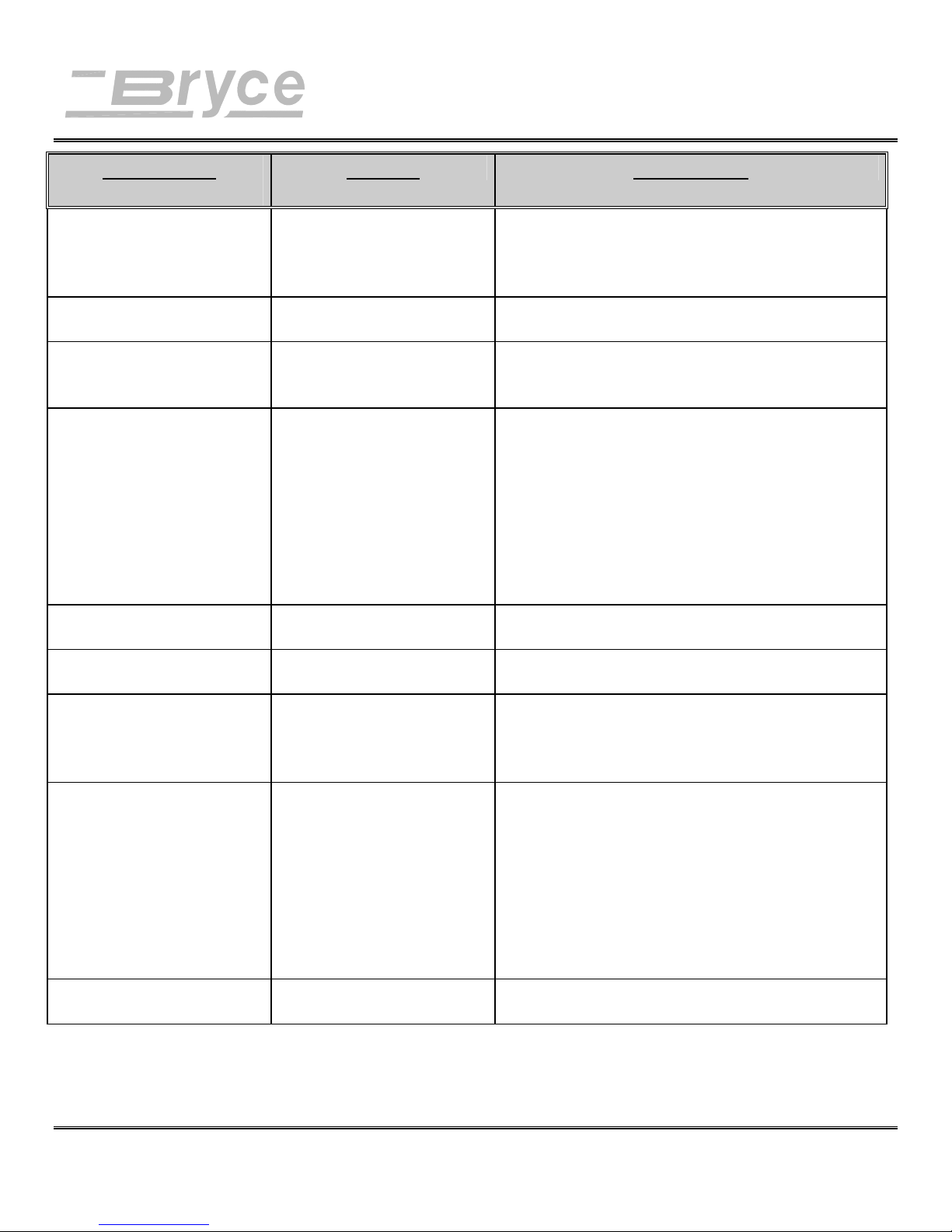
Troubleshooting and Maintenance
SYMPTOM
CAUSE SOLUTION
Optional Fonts not
functioning
Address Too High
(Error Message)
Address Too Low
(Error Message)
Shuttle Jam
(Error Message)
Out of Memory
(Error Message)
Font Card Removed
(Error Message)
Battery Error
(Error Message)
No Barcode Address margin below 5/8"
Barcode (lower right) is
wandering (up and down)
Notes: ___________________________________________________________________________________
_________________________________________________________________________________________
Font Cartridge not installed
correctly
Verify the Font Cartridge label is facing the
operator.
Verify the Font Cartridge is inserted all the way
into the Font Cartridge Slot.
Software Margin incorrect Top Line of the Address is above the edge of the
media. Move the location of the address down.
Software Margin incorrect The Address is below the Bottom edge of the
media. The bottom edge margin must be
increased.
Shuttle is hitting media
Lower Print Head Shaft
dirty.
Print Head Holder
Adjust Print Head Height Adjustment knob
clockwise, so head height is above the media.
Clean shaft with alcohol and soft cotton cloth.
Call Service Representative.
bushings
clogged with paper dust
Overuse of graphics / page
Turn printer off then send again.
information
Connection to font card
incomplete.
Battery is low and cannot
Insert Font Card, turn printer off, then turn printer
on and send again.
Call Service Representative.
maintain the printers
settings when powered
down.
Lower Right Barcode, the distance between the
(1.6 cm) minimum distance
Invalid Zip Code or more
data following Zip Code.
Five (5) Digit Zip Code
turned off.
Belt tension is not adjusted
last line of the address field and the bottom edge
of the media must be at least 5/8 inches (1.6 cm).
Check Zip Code and correct, remove any data
following the Zip Code.
The 5 digit zip code option in the print Main
Menu is Off.
Call Service Representative.
correctly.
Revision A 9K-L USERS MANUAL Section 7 - 5
P/N 90-00860-001
Page 69

Troubleshooting and Maintenance
_________________________________________________________________________________________
Revision A 9K-L USERS MANUAL Section 7 - 6
P/N 90-00860-001
Page 70
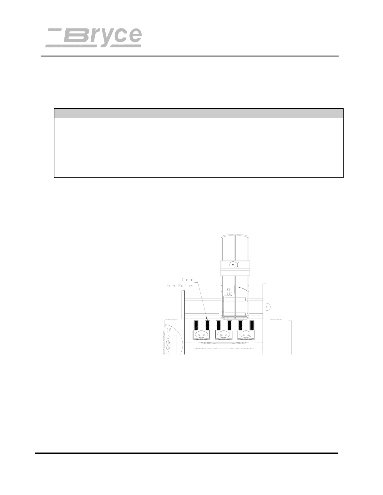
Troubleshooting & Maintenance
PREVENTATIVE
MAINTENANCE:
CLEAN PRINT CARTRIDGE, INK SURFACES AND COVERS WITH PLAIN WATER.
ALL RUBBER ROLLERS CAN BE CLEANED WITH ISOPROPYL, DENATURED & RUBBING
ALCOHOL OR WATER ONLY.
USING ANY OTHER CLEANING SOLVENTS WILL VOID ALL WARRANTIES.
Keep cleaning solvents with petroleum based products from rubber or plastic parts.
Anything but ALCOHOL or WATER will cause premature breakdown of rubber compound.
The 9K-L Printer is designed for trouble free service with a
minimal amount of care. Periodic cleaning of the Feed Rollers,
Right Exit Roller Slider, Left Exit Roller Slider and Lower
Guide assembly will be necessary.
CAUTION!!
Lint and paper dust tends to build up on the feed rollers with
use. When the rollers are glazed or have a yellowish residue,
clean the rollers. Use alcohol to dampen a soft cotton cloth to
clean all rubber rollers.
FEED ROLLERS
PRINT
CARTRIDGE
If the print quality is unacceptable select the Purge Print Head
function from the Setup Menu (see section 6 - 21). If problems
still persist then do the following:
• Remove the Print Cartridge (See chapter 4).
Clean the nozzles with a soft cotton cloth. Use
a dry cloth or one moistened with water to
clean the ink jet cartridge.
• Remove problem print cartridge and install a
new print cartridge.
Revision A 9K-L USERS MANUAL Section 7 -
P/N 90-00860-001
6
Page 71
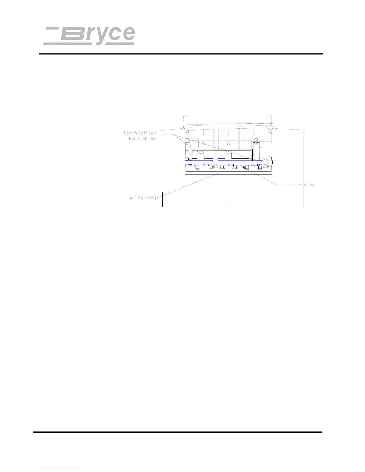
SENSORS
FLOOR
ASSEMBLY
and COVERS
PRINT HEAD
ASSEMBLY
EXIT ROLLER
SLIDERS
Troubleshooting & Maintenance
With use, a film and/or dust builds up on the sensors causing
misfeeds of media. Lift the front door and use compressed air
to blow dust from the sensors.
Periodically wipe the outside and floor assembly with a soft
damp cotton cloth (WATER ONLY).
The print head performs a self cleaning cycle at the service
station before printing and periodically while printing.
If the Exit Roller Sliders were misadjusted, it is possible to get
ink transferred from the media onto the roller and slider
surface. Use water to dampen a soft cloth to remove the ink
from the rollers and sliders.
Revision A 9K-L USERS MANUAL Section 7 -
P/N 90-00860-001
7
Page 72
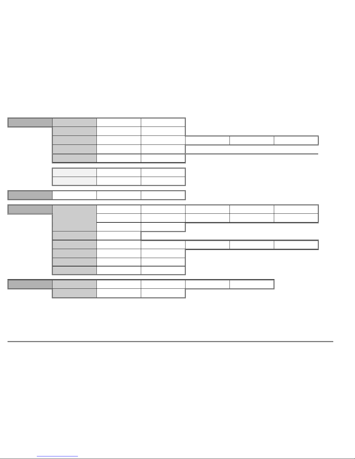
Revision A 9K-L USERS MANUAL Section A - 1
P/N 90-00860-001
Appendix A • Bryce Office Systems 9K-L MAIN MENU Flow Chart
----MAIN MENU----
1. Address Layout
Address Layout
A
. Distance to Right
DIST TO RIGHT +MORE
*4.50 inches -LESS
DIST TO RIGHT +MORE
*100 mm -LESS
Address Layout
B Distance to Bottom
*2.00 inches -LESS
DIST TO BOTTOM +MORE DIST TO BOTTOM +MORE
*50 mm -LESS
Address Layout
C. Line Spacing
LINE SPACING
3 lines/inch
LINE SPACING
4 lines/inch
LINE SPACING
6 lines/inch
LINE SPACING
8 lines/inch
LINE SPACING
*Automatic
Address Layout
D Orientation
ORIENTATION
*Normal
ORIENTATION
Invert
Address Layout
E Orientation Cntrl.
*AUTOMATIC
ORIENTATION CONTROL ORIENTATION CONTROL
MANUAL
c Substituted Address Layout menu selections when ORIENTATION is in Invert.
cAddress Layout
A. Distance to Left
LEFT MARGIN +MORE
*4.50 inches -LESS
LEFT MARGIN +MORE
*100 mm -LESS
cAddress Layout
B Distance to Top
TOP MARGIN +MORE
*2.00 inches -LESS
TOP MARGIN +MORE
*50 mm -LESS
----MAIN MENU----
2. Print Quality
Print Quality
*Executive
Print Quality
Letter
Print Quality
Draft
----MAIN MENU----
3. Font
FONT
dA. Name
eFONT NAME
*Courier
FONT NAME
Sans Serif
FONT NAME
Roman
FONT NAME
Baxter
FONT NAME
Dingbat
FONT NAME
Hancock
FONT NAME
Marina
FONT NAME
Quincy
FONT NAME
Silicon
FONT NAME
Springer
FONT NAME
Stencil
FONT NAME
Windmill
FONT
B. Size
FONT SIZE +LARGER
*12 point -SMALLER
FONT
C. Width
FONT WIDTH
*Normal (100%)
FONT WIDTH
Thin (75%)
FONT WIDTH
Condensed (50%)
FONT WIDTH
Wide (125%)
FONT WIDTH
Expanded (150%)
FONT
D. Bold
BOLD FONT
*Off
BOLD FONT
On
FONT
E. Italic
ITALIC FONT
*Off
ITALIC FONT
On
FONT
F. Outline
OUTLINE FONT
*Off
OUTLINE FONT
On
----MAIN MENU----
4. Barcode
BARCODE
A
. Location
BARCODE LOCATION
*Off
BARCODE LOCATION
Above Address
BARCODE LOCATION
Below Address
BARCODE LOCATION
Lower Right Corner
BARCODE
B. 5 Digit On/Off
5 DIGIT BARCODE
*Off
5 DIGIT BARCODE
On
d To print a list of accessible fonts in their typeface, press the Test button when in the FONT menu and the
selection A. Name is displayed.
e To print a fonts’ character table, press the Test button when in the FONT NAME sub-menu and the name of the
desired font is displayed.
Page 73
Revision A 9K-L USERS MANUAL Section A - 2
P/N 90-00860-001
Appendix A • Bryce Office Systems 9K-L MAIN MENU Flow Chart
----MAIN MENU----
5. Address Recovery
ADDRESS RECOVERY
A
. Get Address
02: John P. Jones
Hit ENTER to Recover
NONE TO RECOVER.
ADDRESS RECOVERY
B. Clear Memory
Clear the +YES
Address Buffer? -NO
----MAIN MENU----
6. Clear Counter
Clear address +YES
(pcs) counter? -NO
Address counter
cleared. Pieces=0
----MAIN MENU----
7. Job Settings
JOB SETTINGS
A
. Load
Load Setting +MORE
from Job #3? -LESS
Printer is set for
Job #3.
JOB SETTINGS
B. Save
Save Settings +MORE
as Job #6? -LESS
Job #6 has been
saved.
Page 74
Revision A 9K-L USERS MANUAL Section A - 3
P/N 90-00860-001
Appendix A • Bryce Office Systems 9K-L SETUP MENU Flow Chart
----SETUP MENU----
1. Heavy Media Mode
HEAVY MEDIA MODE
*Off
HEAVY MEDIA MODE
On
----SETUP MENU----
2. Test Print Head
Print a test +YES
pattern? -NO
Please wait. Test
pattern is printing.
----SETUP MENU----
3. Purge Print Head
Purge Print +YES
Head? -NO
Please wait. Print
head being purged.
----SETUP MENU----
4. Lines Per Address
*06 -LESS
LINES/ADDRESS +MORE
----SETUP MENU----
5. Communications
SERIAL
A
. Baud Rate
BAUD RATE
1200 Baud
BAUD RATE
2400 Baud
BAUD RATE
4800 Baud
BAUD RATE
*9600 Baud
BAUD RATE
19200 Baud
SERIAL
B. Parity
PARITY
*None
PARITY
Even
PARITY
Odd
SERIAL
C. Word Length
WORD LENGTH
7 Data Bits
WORD LENGTH
*8 Data Bits
SERIAL
D. Line Termination
LINE TERMINATION
*CR=CR, LF=LF
LINE TERMINATION
CR=CR+LF LF=LF
LINE TERMINATION
CR=CR LF=CR,LF
LINE TERMINATION
CR=CR+LF LF=CR+LF
----SETUP MENU----
6. Hex Dump Mode
HEX DUMP MODE
*Off
HEX DUMP MODE
On
----SETUP MENU----
7. Language
LANGUAGE
A
. Symbol Set
ISO CHARACTER SET
*ISO 6 ANSI ASCII
ISO CHARACTER SET
ISO 69 FRENCH
ISO CHARACTER SET
ISO 21 GERMAN
ISO CHARACTER SET
ISO 4 UK
ISO CHARACTER SET
ISO 60 NORW / DAN
ISO CHARACTER SET
ISO 11 SWED / FIN
ISO CHARACTER SET
ISO 15 ITALIAN
ISO CHARACTER SET
ISO 17 SPANISH
ISO CHARACTER SET
ISO 61 NOR / DAN
ISO CHARACTER SET
ISO 10 SWED / FIN
ISO CHARACTER SET
ISO 16 PORTUGUESE
ISO CHARACTER SET
ISO 8859
ISO CHARACTER SET
ROMAN 8
ISO CHARACTER SET
WINDOWS LATIN 1
ISO CHARACTER SET
PC 8
LANGUAGE
B. Inch/Millimeter
MEASUREMENT UNITS
*Inch
MEASUREMENT UNITS
Millimeter
LANGUAGE
C. Menu Language
DISPLAY LANGUAGE
*English
DISPLAY LANGUAGE
German
DISPLAY LANGUAGE
French
DISPLAY LANGUAGE
Italian
DISPLAY LANGUAGE
Spanish
DISPLAY LANGUAGE
Dutch
DISPLAY LANGUAGE
Polish
----SETUP MENU----
8. Env. Feed Delay
FEED DELAY +MORE
* 0.0 SEC. -LESS
----SETUP MENU----
9. Env. Auto Eject
AUTO EJECT MODE
*On
AUTO EJECT MODE
Off
----SETUP MENU----
10. Rom Revision #
ROM REV. = P72693
MAINT COUNT=12345678
f To print a list of the Main Menu and Setup Menu settings, press the Test button when ROM REV is displayed.
Page 75
APPENDIX B Hex Chart
HEX CHART
MSB
DECIMAL
0163248648096112
HEX
0
1
2
3
4
LSB 5
6
7
8
9
10
11
12
13
14
15
HEX CHART
0
1
2
3
4
5
6
7
8
9
A
B
C
D
E
F
01234567
NUL DLE SP 0 @ P
SOH DC1 ! 1 A Q a q
STX DC2
ETX DC3 # 3 C S c s
EOT DC4 $ 4 D T d t
ENQ NAK % 5 E U e u
ACK SYN & 6 F V f v
BEL ETB
BS CAN ( 8 H X h x
HT EM ) 9 I Y i y
LF SUB *
VT ESC +
FF FS
CR GS
SO RS
SI US / ? O
"
'
,
.
2BRbr
7GWgw
:
;
<L \l |
=M ] m }
>N^n
`
JZjz
K[k{
_
oDEL
p
~
Example: The capital letter A is a HEX 41. Find the letter A on the above chart, and look towards the top of the
chart (MSB) and the locate the HEX number 4. Then look to the left side of the chart (LSB) and
locate the Hex number 1. Therefore the HEX number is MSB 4 and LSB 1= 41.
Revision A 9K-L USERS MANUAL Section B - 1
P/N 90-00860-001
Page 76
Appendix C PCL Command Codes
Introduction
The 9K-L Address Printer emulates the listed PCL 5 printer command codes. The 9K-L Address Printer will
virtually handle media as an HP1200 would using these printer commands. Additional printer commands have
been added to allow control of special printer addressing functions and addressing needs.
The printer command codes are sets of characters that allow your computer software to override the address
printer menu selections as fonts, print quality, etc. so customized address formats can be created.
PCL Command Codes
Code Name Symbol HEX
Value
Line Feed <LF> 0A 10 Causes the printer to advance the paper one line at
Form Feed <FF> 0C 12 Causes the printer to advance the paper to the next top
Carriage
<CR> 0D 13 Causes the printer to move the current print position to
Return
Escape <Å> 1B 27 Indicates to the printer that the characters immediately
Space <SP> 20 32 Causes the printer to move the current print position one
DEC
Value
Description
current line spacing.
of form.
the left margin. Does not cause a paper advance.
following are part of a printer command.
character to the right.
Revision A 9K-L USERS MANUAL Section C - 1
P/N 90-00860-001
Page 77
Appendix C PCL Command Codes
PCL parameterized escape sequences
Printer Feature Printer
Command
Initialization
Reset ÅE 1B 45 027 069 Defines reset conditions
Hard Reset ÅH 1B 48 027 072 Performs reset plus clears
Page Control
Page Size Default Å&l0A 1B 26 6C 30 41 027 038 108 048 065 #10 Envelope values
Page Size Executive Å&l1A 1B 26 6C 31 41 027 038 108 049 065 7.25 x 10.5 inches (18.3 x
Page Size Letter Å&l2A 1B 26 6C 32 41 027 038 108 050 065 8.5 x 11 inches (21.6 x
Page Size Legal Å&l3A 1B 26 6C 33 41 027 038 108 051 065 8.5 x 14 inches (21.6 x
Page Size A4 Å&l26A 1B 26 6C 32 36
Page Size Mon Env Å&l80A 1B 26 6C 38 30
Page Size #10 Env Å&l81A 1B 26 6C 38 31
Page Size DL Env Å&l90A 1B 26 6C 39 30
Page Size C5 Env Å&l91A 1B 26 6C 39 31
Page Size B5 Env Å&l100A 1B 26 6C 31 30
Page Size 9.4” x 15” Å&l101A 1B 26 6C 31 30
Left Margin Å&a#L 1B 26 61 #..# 4C 027 038 097 #..# 076 # of Columns. Defined by
Clear Horiz Margins Å9 1B 39 027 057
Top Margin Å&l#E 1B 26 6C #..# 45 027 038 108 #..# 069 # of Dots from origin
Page Length c Å&l#P 1B 26 6C #..# 50 027 038 108 #..# 080 # of Lines
Text Length Å&l#F 1B 26 6C #..# 46 027 038 108 #..# 070 # of Lines
Horiz Motion Index
Å&k#H 1B 26 6B #..# 48 027 038 107 #..# 072 # of 1/120 inch (1/47 cm)
(HMI)
HEX
Equivalent
41
41
41
41
41
30 41
31 41
DEC Equivalent Description
all permanent macros,
fonts, and address
recovery buffer
26.7 cm)
27.9 cm)
35.6)
027 038 108 050 054 065 210 x 297 mm
027 038 108 056 048 065 7.5 x 3.88 inches (19.1 x
9.9 cm)
027 038 108 056 049 065 9.5 x 4.1 inches (24.1 x
10.4 cm)
027 038 108 057 048 065 220 x 110 mm
027 038 108 057 049 065 229 x 162 mm
027 038 108 049 048 048
238 x 104 mm
065
027 038 108 049 048 049
065
9.4 x 15 inches (23.9 x
38.1 cm)
current HMI.
Revision A 9K-L USERS MANUAL Section C - 2
P/N 90-00860-001
Page 78
Appendix C PCL Command Codes
PCL parameterized escape sequences
Printer Feature Printer
Command
Page Control
Vertical Motion
Å&l#C 1B 26 6C #..# 43 027 038 108 #..# 067 # of 1/48 inch (1/19 cm)
Index (VMI)
Line Spacing Å&l#D 1B 26 6C #..# 44 027 038 108 #..# 068 # of lines per inch
Page Eject Å&l0H 1B 26 6C 30 48 027 038 108 048 072
Heavy Media Mode
Å&l6H 1B 26 6C 36 48 027 038 108 054 072 Effects feed mode
OFF
Heavy Media Mode
Å&l9H 1B 26 6C 39 48 027 038 108 057 072 Effects feed mode
ON
Page Orientation Å&l0O 1B 26 6C 30 4F 027 038 108 048 079 Portrait
Å&l2O 1B 26 6C 32 4F 027 038 108 050 079 Reverse Portrait
Dry Hold Time Å&b#T 1B 26 62 #..# 54 027 038 098 #..# 084 Minimum time between
Page Height Å+s#H 1B 2B 73 #..#
Page Width c Å+s#W 1B 2B 73 #..#
Cursor Positioning
Horizontal Position Å&a#C 1B 26 61 #..# 43 027 038 097 #..# 067 Move to Column no.
Å*p#X 1B 2A 70 #..# 58 027 042 112 #..# 088 # of Dots
Å&a#H 1B 26 61 #..# 48 027 038 097 #..# 072 # of Decipoints (1/720
Vertical Position Å&a#R 1B 26 61 #..# 52 027 038 097 #..# 082 Move to Row no.
Å*p#Y 1B 2A 70 #..# 59 027 042 112 #..# 089 # of Dots
Å&a#V 1B 26 61 #..# 56 027 038 097 #..# 086 # of Decipoints (1/720
HEX
Equivalent
48
57
DEC Equivalent Description
selection
selection
pieces in 1/10 seconds.
Specifies time from
leading edge to leading
edge.
Dflt = 0. Max. = 300
027 043 115 #..# 072 # = height in PCL units.
(1/300 in.) (1/118 cm)
Range of values is 1050 ...
4500
(3 to 15 in.) (7.62 to 38.1
cm).
027 043 115 #..# 087 # = width in PCL units
(1/300 in.) (1/118 cm)
Range of values is 1500 ..
2820 (5 to 9.4 in.) (12.7 to
23.9 cm).
inch) (1/283 cm)
inch) (1/283 cm)
Revision A 9K-L USERS MANUAL Section C - 3
P/N 90-00860-001
Page 79
Appendix C PCL Command Codes
PCL parameterized escape sequences
Printer Feature Printer
Command
Half Line Feed Å= 1B 3D 027 061 Half of current VMI
HEX
Equivalent
DEC Equivalent Description
Revision A 9K-L USERS MANUAL Section C - 4
P/N 90-00860-001
Page 80
Appendix C PCL Command Codes
PCL parameterized escape sequences
Printer Feature Printer
Command
Cursor Positioning
Line Termination Å&k#G
Font Selection
(Primary)
0 1B 26 6B 30 47 027 038 107 048 071 CR=CR, LF=LF, FF=FF
1 1B 26 6B 31 47 027 038 107 049 071 CR=CR+LF, LF=LF,
2 1B 26 6B 32 47 027 038 107 050 071 CR=CR, LF=CR+LF,
3 1B 26 6B 33 47 027 038 107 051 071 CR=CR+LF, LF=CR+LF,
Symbol Set Å(ID 1B 28 # .. # 027 040 # .. #
Å(0D 1B 28 30 44 027 040 048 068 ISO 60 Norwegian ver 1
Å(0I 1B 28 30 49 027 040 048 073 ISO 15 Italian
Å(0N 1B 28 30 4E 027 040 048 078 ISO 8859
Å(0S 1B 28 30 53 027 040 048 083 ISO 11 Swedish
Å(0U 1B 28 30 55 027 040 048 085 ANSI ASCII
Å(1D 1B 28 31 44 027 040 049 068 ISO 61 Norwegian ver 2
Å(1E 1B 28 31 45 027 040 049 069 ISO 4 UK
Å(1F 1B 28 31 46 027 040 049 070 ISO 69 French
Å(1G 1B 28 31 47 027 040 049 071 ISO 21 German
Å(2S 1B 28 32 53 027 040 050 083 ISO 17 Spanish
Å(3S 1B 28 33 53 027 040 051 083 ISO 10 Swedish
Å(4S 1B 28 34 53 027 040 052 083 ISO 16 Portuguese
Å(8U 1B 28 38 55 027 040 056 085 Roman 8
Å(10U 1B 28 31 30 55 027 040 049 048 085 PC - 8
Å(12U 1B 28 31 32 55 027 040 049 050 085 PC 850
Å(19U 1B 28 31 39 55 027 040 049 057 085 Windows 3.1 Latin
Print Quality Å(s#Q
Å(s0Q 1B 28 73 30 51 027 040 115 048 081 Quality = Draft
Å(s1Q 1B 28 73 31 51 027 040 115 049 081 Quality = Letter
Å(s2Q 1B 28 73 32 51 027 040 115 050 081 Quality = Executive
Spacing h Å(s#P
0 1B 28 73 30 50 027 040 115 048 080 Fixed Spacing
1 1B 28 73 31 50 027 040 115 049 080 Proportional Spacing
Height Å(s#V 1B 28 73 #..# 56 027 040 115 #..# 086 Point Size #/72 inch (1/28
HEX
Equivalent
DEC Equivalent Description
FF=FF
FF=CR+FF
FF=CR+FF
cm)
Revision A 9K-L USERS MANUAL Section C - 5
P/N 90-00860-001
Page 81
Appendix C PCL Command Codes
PCL parameterized escape sequences
Printer Feature Printer
Command
Font Selection
(Primary)
Style Å(s#S
0 1B 28 73 30 53 027 040 115 048 083 Upright
1 1B 28 73 31 53 027 040 115 049 083 Italic
2 1B 28 73 32 53 027 040 115 050 083 Expanded (150%)
3 1B 28 73 33 53 027 040 115 051 083 Italic, Expanded (150%)
4 1B 28 73 34 53 027 040 115 052 083 Thin (75%)
5 1B 28 73 35 53 027 040 115 053 083 Italic, Thin (75%)
8 1B 28 73 38 53 027 040 115 056 083 Condensed (50%)
9 1B 28 73 39 53 027 040 115 057 083 Italic, Condensed (50%)
16 1B 28 73 31 36
17 1B 28 73 31 37
32 1B 28 73 33 32
33 1B 28 73 33 33
34 1B 28 73 33 34
35 1B 28 73 33 35
36 1B 28 73 33 36
37 1B 28 73 33 37
40 1B 28 73 34 30
41 1B 28 73 34 31
48 1B 28 73 34 38
49 1B 28 73 34 39
Stroke Weight Å(s#B
0 1B 28 73 30 42 027 040 115 048 066 Normal
HEX
Equivalent
53
53
53
53
53
53
53
53
53
53
53
53
DEC Equivalent Description
027 040 115 049 054 083 Wide (125%)
027 040 115 049 055 083 Italic, Wide (125%)
027 040 115 051 050 083 Hollow
027 040 115 051 051 083 Hollow, Italic
027 040 115 051 052 083 Hollow, Expanded (150%)
027 040 115 051 053 083 Hollow, Italic, Expanded
(150%)
027 040 115 051 054 083 Hollow, Thin (75%)
027 040 115 051 055 083 Hollow, Italic, Thin (75%)
027 040 115 052 048 083 Hollow, Condensed (50%)
027 040 115 052 049 083 Hollow, Italic, Condensed
(50%)
027 040 115 052 056 083 Hollow, Wide (125%)
027 040 115 052 057 083 Hollow, Italic, Wide
(125%)
Revision A 9K-L USERS MANUAL Section C - 6
P/N 90-00860-001
Page 82
Printer Feature Printer
Command
3 1B 28 73 33 42 027 040 115 051 066 Bold
Appendix C PCL Command Codes
PCL parameterized escape sequences
HEX
Equivalent
DEC Equivalent Description
Revision A 9K-L USERS MANUAL Section C - 7
P/N 90-00860-001
Page 83
Appendix C PCL Command Codes
PCL parameterized escape sequences
Printer Feature Printer
Command
Font Selection
(Primary)
Typeface Å(s#T
Font Selection
3 1B 28 73 33 54 027 040 115 051 084 Courier
4 1B 28 73 34 54 027 040 115 052 084 San Serif
5 1B 28 73 35 54 027 040 115 053 084 Roman
61440 1B 28 73 36 31
61441 1B 28 73 36 31
Font Selection Å(#X 1B 28 #..# 58 027 040 #..# 088 Font ID # from download
Font Selection
(Secondary)
Symbol Set Å)ID 1B 29 # .. # 027 041 # .. #
Å)0D 1B 29 30 44 027 041 048 068 ISO 60 Norwegian ver 1
Å)0I 1B 29 30 49 027 041 048 073 ISO 15 Italian
Å)0N 1B 29 30 4E 027 041 048 078 ISO 8859
Å)0S 1B 29 30 53 027 041 048 083 ISO 11 Swedish
Å)0U 1B 29 30 55 027 041 048 085 ANSI ASCII
Å)1D 1B 29 31 44 027 041 049 068 ISO 61 Norwegian ver 2
Å)1E 1B 29 31 45 027 041 049 069 ISO 4 UK
Å)1F 1B 29 31 46 027 041 049 070 ISO 69 French
Å)1G 1B 29 31 47 027 041 049 071 ISO 21 German
Å)2S 1B 29 32 53 027 041 050 083 ISO 17 Spanish
Å)3S 1B 29 33 53 027 041 051 083 ISO 10 Swedish
Å)4S 1B 29 34 53 027 041 052 083 ISO 16 Portuguese
Å)8U 1B 29 38 55 027 041 056 085 Roman 8
Å)10U 1B 29 31 30 55 027 041 049 048 085 PC - 8
Å)12U 1B 29 31 32 55 027 041 049 050 085 PC 850
Å)19U 1B 29 31 39 55 027 041 049 057 085 Windows 3.1 Latin
Print Quality Å)s#Q
Å)s0Q 1B 29 73 30 51 027 041 115 048 081 Quality = Draft
Å)s1Q 1B 29 73 31 51 027 041 115 049 081 Quality = Letter
Å)s2Q 1B 29 73 32 51 027 041 115 050 081 Quality = Executive
Spacing h Å)s#P
0 1B 29 73 30 50 027 041 115 048 080 Fixed Spacing
HEX
Equivalent
34 34 30 54
34 34 31 54
DEC Equivalent Description
027 040 115 054 049 052
External (First)
052 048 084
027 040 115 054 049 052
052 049 084
External (Second)
If available
Revision A 9K-L USERS MANUAL Section C - 8
P/N 90-00860-001
Page 84
Appendix C PCL Command Codes
PCL parameterized escape sequences
Printer Feature Printer
Command
Font Selection
(Secondary)
1 1B 29 73 31 50 027 041 115 049 080 Proportional Spacing
Height Å)s#V 1B 29 73 #..# 56 027 041 115 #..# 086 Point Size #/72 inch (1/28
Style Å)s#S
0 1B 29 73 30 53 027 041 115 048 083 Upright
1 1B 29 73 31 53 027 041 115 049 083 Italic
2 1B 29 73 32 53 027 041 115 050 083 Expanded (150%)
3 1B 29 73 33 53 027 041 115 051 083 Italic, Expanded (150%)
4 1B 29 73 34 53 027 041 115 052 083 Thin (75%)
5 1B 29 73 35 53 027 041 115 053 083 Italic, Thin (75%)
8 1B 29 73 38 53 027 041 115 056 083 Condensed (50%)
9 1B 29 73 39 53 027 041 115 057 083 Italic, Condensed (50%)
16 1B 29 73 31 36
17 1B 29 73 31 37
32 1B 29 73 33 32
33 1B 29 73 33 33
34 1B 29 73 33 34
35 1B 29 73 33 35
36 1B 29 73 33 36
37 1B 29 73 33 37
40 1B 29 73 34 30
41 1B 29 73 34 31
48 1B 29 73 34 38
49 1B 29 73 34 39 53 027 041 115 052 057 083 Hollow, Italic, Wide (125%)
Stroke Weight Å)s#B
HEX
Equivalent
53
53
53
53
53
53
53
53
53
53
53
DEC Equivalent Description
cm)
027 041 115 049 054 083 Wide (125%)
027 041 115 049 055 083 Italic, Wide (125%)
027 041 115 051 050 083 Hollow
027 041 115 051 051 083 Hollow, Italic
027 041 115 051 052 083 Hollow, Expanded (150%)
027 041 115 051 053 083 Hollow, Italic, Expanded
(150%)
027 041 115 051 054 083 Hollow, Thin (75%)
027 041 115 051 055 083 Hollow, Italic, Thin (75%)
027 041 115 052 048 083 Hollow, Condensed (50%)
027 041 115 052 049 083 Hollow, Italic, Condensed
(50%)
027 041 115 052 056 083 Hollow, Wide (125%)
Revision A 9K-L USERS MANUAL Section C - 9
P/N 90-00860-001
Page 85
Printer Feature Printer
Command
0 1B 29 73 30 42 027 041 115 048 066 Normal
3 1B 29 73 33 42 027 041 115 051 066 Bold
Appendix C PCL Command Codes
PCL parameterized escape sequences
HEX
Equivalent
DEC Equivalent Description
Revision A 9K-L USERS MANUAL Section C - 10
P/N 90-00860-001
Page 86
Appendix C PCL Command Codes
PCL parameterized escape sequences
Printer Feature Printer
Command
Font Selection
(Secondary)
Typeface Å)s#T
Underline
3 1B 29 73 33 54 027 041 115 051 084 Courier
4 1B 29 73 34 54 027 041 115 052 084 San Serif
5 1B 29 73 35 54 027 041 115 053 084 Roman
61440 1B 29 73 36 31
61441 1B 29 73 36 31
Underline Å&d#D
Underline On 0 1B 26 64 30 44 027 038 100 48 068
Underline On 3 1B 26 64 33 44 027 038 100 51 068
Underline Off Å&d@ 1B 26 64 40 027 038 100 064
Macros d
Macro ID Å&f#Y 1B 26 66 #..# 59 027 038 102 #..# 089 # is macro ID
Macro Control Å&f#X
0 1B 26 66 30 58 027 038 102 048 088 Start macro definition (last
1 1B 26 66 31 58 027 038 102 049 088 Stop macro definition
2 1B 26 66 32 58 027 038 102 050 088 Execute Macro (last ID
3 1B 26 66 33 58 027 038 102 051 088 Call Macro (last ID
4 1B 26 66 34 58 027 038 102 052 088 Enable macro for auto
5 1B 26 66 35 58 027 038 102 053 088 Disable auto overlay
6 1B 26 66 36 58 027 038 102 054 088 Delete all Macros
7 1B 26 66 37 58 027 038 102 055 088 Delete all temp macros
HEX
Equivalent
34 34 30 54
34 34 31 54
DEC Equivalent Description
027 041 115 054 049 052
External (First)
052 048 084
027 041 115 054 049 052
052 049 084
External (Second)
If available
ID specified)
specified). Use current
modified print
environment. Changes
retained on completion
specified). Use current
modified print
environment. Restore
prior environment on
completion.
overlay (last ID specified)
Revision A 9K-L USERS MANUAL Section C - 11
P/N 90-00860-001
Page 87
Appendix C PCL Command Codes
PCL parameterized escape sequences
Printer Feature Printer
Command
Programming
Hex Dump Mode
8 1B 26 66 38 58 027 038 102 056 088 Delete Macro (last ID
9 1B 26 66 39 58 027 038 102 057 088 Make macro temp (last ID
10 1B 26 66 31 30
ÅY 1B 59 027 089 Data printed as hex
ON
Hex Dump Mode
ÅZ 1B 5A 027 090
OFF
Font Management
Assign Font ID # Å*c#D 1B 2A 63 #..# 44 027 042 099 #..# 068 # is Font ID
Font Control Å*c#F
Soft Font Creation e
0 1B 2A 63 30 46 027 042 099 048 070 Delete all Fonts
1 1B 2A 63 31 46 027 042 099 049 070 Delete temp fonts
2 1B 2A 63 32 46 027 042 099 050 070 Delete last font
3 1B 2A 63 33 46 027 042 099 051 070 Delete Character
4 1B 2A 63 34 46 027 042 099 052 070 Make font temp
5 1B 2A 63 35 46 027 042 099 053 070 Make font permanent
Font Descriptor Å)s#W
[data]
Character Code Å*c#E 1B 2A 63 #..# 45 027 042 099 #..# 069 ASCII code no.
Download Character Å(s#W
[data]
Raster Graphics
Raster Graphics
Compression
Å*b#M
0 1B 2A 62 30 4D 027 042 098 048 077 Uncompressed format
2 1B 2A 62 32 4D 027 042 098 050 077 TIFF format
3 1B 2A 62 33 4D 027 042 098 051 077 Delta Row compression
4 1B 2A 62 34 4D 027 042 098 052 077 Reserved
HEX
Equivalent
58
1B 29 73 #..# 57
data
1B 28 73 #..# 57
data
DEC Equivalent Description
specified)
specified)
027 038 102 049 048 088 Make macro perm (last ID
specified)
numbers, ESC and
Control codes not
executed.
027 041 115 #..# 087 data Laser Jet soft fonts are
supported. These fonts
always have a 64 byte
descriptor. Desk Jet fonts
are not supported.
027 040 115 #..# 087 data
Revision A 9K-L USERS MANUAL Section C - 12
P/N 90-00860-001
Page 88
Appendix C PCL Command Codes
PCL parameterized escape sequences
Printer Feature Printer
Command
Transfer graphics by
plane
Transfer Raster
Graphics data
Raster Y Offset
Å*b #V 1B 2A 62 # 56
Å*b#W
[data]
Å*b #Y
[data]
Start Raster Graphics
Å*r#A
0 1B 2A 72 30 41 027 042 114 048 065 Place to left most position
1 1B 2A 72 31 41 027 042 114 049 065 Place at current position
End Raster Graphics
Å*rB 1B 2A 72 42 027 042 114 066
Å*rC 1B 2A 72 43 027 042 114 067 Resets left margin to 0
Set Raster Graphics
Width
Set Raster Graphics
Height
Simple Color
Å*r#S 1B 2A 72 #..# 53 027 042 114 #..# 083 Set number of pixels
Å*r#T 1B 2A 72 # 54 027 042 114 # 084 Height is raster rows
Å*r#U
Black pallet 1 1B 2A 72 31 55 027 042 114 049 085 1 plane
Raster Graphics
Resolution
Å*t#R
75 1B 2A 72 37 35
150 1B 2A 72 31 35
300 1B 2A 72 33 30
HEX
Equivalent
[data]
1B 2A 62 #..# 57
[data]
1B 2A 62 #..# 59
[data]
52
30 52
30 52
DEC Equivalent Description
027 042 098 # 086 [data]
027 042 098 #..# 087
Number of bytes
[data]
027 042 098 #..# 089
Number of dots
[data]
027 042 116 055 055 082 75 dots per inch
027 042 116 049 053 048
150 dots per inch
082
027 042 116 051 048 048
300 dots per inch
082
c The Page Width & Page Length printer commands function like the Page Size command. Using these
commands automatically enables Page Eject and disables overlay macros. Both the Page Width and Page
Length commands can be used independently and will only change the width or length to the maximum
allowable page size of 9.4 x 15 inches (23.9 x 38.1 cm). Setting the cursor positioning commands, margin
settings, print data, etc. to cause printing beyond the pages size dimensions will be cropped.
d Only one overlay macro can be used at a time, and cannot be recursive. The overlay macros need print
quality, page parameters, etc. to determine the printers’ page setup.
e Soft font creation is in HP non compressed Bit Map Font Format.
h The resident fonts are scaleable from 8 to 30 points. If a desired font spacing does not match the font
selected an internal font will be substituted. For fixed spacing the substitute font will be Courier, and Sans Serif
Revision A 9K-L USERS MANUAL Section C - 13
P/N 90-00860-001
Page 89

Appendix C PCL Command Codes
for proportionally spaced fonts. Characteristics of the font being replaced, such as point size, print width, etc.,
will be matched by the substituted font.
To determine page size or cusor movement in Dots multiply by
300 Dots /inch (2.54 cm) for Horizontal and
300 Dots /inch (2.54 cm) for Vertical. Example: a Letter size page of 8.5 x 11 inches (21.6 x 27.9 cm) is 2550 x
3300 Dots
Revision A 9K-L USERS MANUAL Section C - 14
P/N 90-00860-001
Page 90
Appendix C PCL Command Codes
PCL parameterized escape sequences
To utilize the 9K-L address printers internal bar-coding features, records are searched for a valid ZIP, ZIP + 4,
Delivery Point Bar Code (DPBC) or DPBC with a check sum. For ZIP + 4 or a 11 digit DPBC, a checksum is
computed for printing a USPS Postnet bar-code with framing bars. The position of the Postnet bar-code is
determined by the printers menu setup or the bar-code location commands in effect. Bar-codes will not be
printed outside of the printers’ Page Size setup.
Printer Feature Printer
Command
Bar Code
Non - address data
Å+b#A Marks data that is not part
markers f
1 1B 2B 62 31 41 027 043 098 49 065 marks the end of non-
2 1B 2B 62 32 41 027 043 098 50 065 marks the beginning of
5 Digit Bar Codes Å+b#D
0 1B 2B 62 30 44 027 043 098 048 068 Don’t print 5 Digit Bar
1 1B 2B 62 31 44 027 043 098 049 068 Print all Bar Codes for
Bar Code Å+b#E
Bar Code -
0 1B 2B 62 30 45 027 043 098 048 069 Disable Bar Code
1 1B 2B 62 31 45 027 043 098 049 069 Enable Bar Code
Å+b#H 1B 2B 62 #..# 48 027 043 098 #..# 072 # of Decipoints
Horizontal
Bar Code Placement Å+b#P 1B 2B 62 #..# 50 027 043 098 #..# 080 Distance in 1/10 inch (1/4
i
0 1B 2B 62 30 50 027 043 098 048 080 Bar Code in lower right
1 1B 2B 62 31 50 027 043 098 049 080 Bar Code above address
2 1B 2B 62 32 50 027 043 098 050 080 Bar Code below address
3 1B 2B 62 33 50 027 043 098 051 080 Print Bar Code at specified
HEX
Equivalent
DEC
Equivalent
Description
of destination address.
address data
the non-address data.
Codes
zip, zip + 4, and DPBC.
(1/720 inch) (1/283 cm)
cm) units from right edge
of media. Value of 0
indicates edge of media
(default position)
horizontal & vertical
position, otherwise print
Bar Code in default
position
Revision A 9K-L USERS MANUAL Section C - 15
P/N 90-00860-001
Page 91
Appendix C PCL Command Codes
PCL parameterized escape sequences
Printer Feature Printer
Command
Bar Code
HEX
Equivalent
DEC
Equivalent
Description
Bar Code - Vertical Å+b#V 1B 2B 62 #..# 56 027 043 098 #..# 086 VMI # in Decipoints
(1/720 inch) from bottom
of page to bottom of barcode
ZIP Code command
Bar Code -g
Å+b#Znnn 1B 2B 62 #..#
5A nnn
027 043 098 #..# 090 nnn #= number of characters in
the ZIP Code string.
n = the ASCII
representation of the ZIP
code string.
Å+b5Z
nnnnn
1B 2B 62 35 5A
nnnnn
027 043 098 053 090
nnnnn
n = the ASCII
representation of the ZIP
code string. Must contain 5
digits.
Å+b9Z
nnnnnnnnn
1B 2B 62 39 5A
nnnnnnnnn
027 043 098 057 090
nnnnnnnnn
n = the ASCII
representation of the ZIP
code string. Must contain 9
digits.
Å+b11Z
nnnnnnnnnn
n
1B 2B 62 31 31
5A
nnnnnnnnnnn
027 043 098 49 49 090
nnnnnnnnnnn
n = the ASCII
representation of the ZIP
code string. Must contain
11 digits.
Å+b12Z
nnnnnnnnnn
nn
1B 2B 62 31 32
5A
nnnnnnnnnnnn
027 043 098 049 050 090
nnnnnnnnnnnn
n = the ASCII
representation of the ZIP
code string. Must contain
12 digits.
f Use a pair of escape sequences, the first one before the data that is not part of the destination address
such as return addresses, graphics, messages, etc. and the other to mark the end.
g Use Zip Code command when two ZIP codes are being sent. The first ZIP code will be printed without a
bar-code. The second ZIP code in the Zip Code command string will print a corresponding bar-code but
not print the ZIP code. The Zip Code command only overrides the bar-code command for the present
address.
Revision A 9K-L USERS MANUAL Section C - 16
P/N 90-00860-001
Page 92

Appendix C PCL Command Codes
i Use the Å+b#H and Å+b#V commands to position the bar code. Measure the position from the right-
hand corner of the leading edge of the media, not the upper left-hand corner.
Revision A 9K-L USERS MANUAL Section C - 17
P/N 90-00860-001
Page 93
0 16
1 17
2 18
3 19
4 20
5 21
6 22
7 23
8 24
9 25
<LF>
10
11
<FF>
12
<CR>
13
14 30
15 31
APPENDIX D Character Sets
9K-L CHARACTER SET
(Modeled after PC 850 Character Table)
26
<ESC>
27
28
29
<SP>
0
32
@
48
64 P 80 ` 96 p 112Ç 128É 144á 160
!
33 1 49 A 65 Q 81 a 97 q 113ü 129æ 145í 161
"
34 2 50 B 66 R 82 b 98 r 114é 130Æ 146ó 162
#
35 3 51 C 67 S 83 c 99 s 115â 131ô 147ú 163
$
36 4 52 D 68 T 84 d 100t 116ä 132ö 148ñ 164
%
37 5 53 E 69 U 85 e 101u 117à 133ò 149Ñ 165Á 181
&
38 6 54 F 70 V 86 f 102v 118å 134û 150
'
39 7 55 G 71 W 87 g 103w 119ç 135ù 151
(
40 8 56 H 72 X 88 h 104x 120ê 136ÿ 152¿ 168
)
41 9 57 I 73 Y 89 i 105y 121ë 137Ö 153
*
42 : 58 J 74 Z 90 j 106z 122è 138Ü 154
+
43 ; 59 K 75 [ 91 k 107{ 123ï 139ø 155½ 171
,
44 < 60 L 76 \ 92 l 108| 124î 140£ 156
-
45 = 61 M 77 ] 93 m 109} 125ì 141Ø 157¡ 173¢ 189
.
46 > 62 N 78 ^ 94 n 110~ 126Ä 142
/
47 ? 63 O 79 _ 95 o 111
127
Å
143ƒ 159» 175
158
░
176└ 192
▒
177┴ 193
▓
178┬ 194
│
179├ 195
┤
180─ 196
┼
197
ª
Â
166
182ã 198 Í 214 µ 230
°
À
167
183Ã 199 Î 215
╚
©
200
184
╣
®
185╔ 201 ┘ 217
169
║
186╩ 202 ┌ 218
170
╗
187╦ 203 █ 219
╝
188╠ 204 ▄ 220
172
═
205
┐
191
╬
206
¤
207
«
174¥ 190
ð
Ó
208
224
Ð
ß
209
225
Ê
210 Ô 226
Ë
211 Ò 227
È
212 õ 228
Õ
213
229 § 245
Þ
231
þ
Ï
232
216
Ú
233 ¨ 249
Û
234
Ù
235
236 252
|
237 253
221
Ì
222 ¯ 238
▀
223
´
239
-
240
±
241
242
243
¶
244
246
¸
247
º
248
•
250
251
254
™
255
The following industry standard character substitution techniques are utilized:
ISO # Character
Set Name
6 ANSI ASCII 0U # $ @ [ \ ] ^ ` { | } ~
69 French 1F £ $ à ° ç § ^ µ é ù è ¨
21 German 1G # $ § Ä Ö Ü ^ ` ä ö ü ß
4 United Kingdom 1E £ $ @ [ \ ] ^ ` { | } ¯
60 Norwegian/Danish 0D # $ @ Æ Ø Å ^ ` æ ø å ¯
11 Swedish/Finnish 0S # ¤ É Ä Ö Å Ü é ä ö å ü
15 Italian 0I £ $ § ° ç é ^ ù à ò è ì
17 Spanish 2S £ $ § ¡ Ñ ¿ ^ ` ° ñ ç ~
61 Norwegian/Danish 1D § $ @ Æ Ø Å ^ ` æ ø å |
16 Portuguese 4S # $ § Ã Ç Õ ^ ` ã ç õ °
10 Swedish 3S # ¤ @ Ä Ö Å ^ ` ä ö å ¯
Revision A 9K-L USERS MANUAL Section D - 1
P/N 90-00860-001
International Character Substitution
ID # 35 36 64 91 92 93 94 96 123 124 125 126
Page 94
APPENDIX D Character Sets
9K-L CHARACTER SET
(Modeled after 8859 Latin Character Table)
0 16
1 17
2 18
3 19
4 20
5 21
6 22
7 23
8 24
9 25
<LF>
10
11
<FF>
12
<CR>
13
14 30
15 31
The ID# for the ISO 8859 Character Set is (0N).
<SP>
32
0
@
48
64 P 80 ` 96 p 112
!
33 1 49 A 65 Q 81 a 97 q 113
"
34 2 50 B 66 R 82 b 98 r 114
#
35 3 51 C 67 S 83 c 99 s 115
$
36 4 52 D 68 T 84 d 100t 116
%
37 5 53 E 69 U 85 e 101u 117
&
38 6 54 F 70 V 86 f 102v 118
'
39 7 55 G 71 W 87 g 103w 119
(
40 8 56 H 72 X 88 h 104x 120
)
41 9 57 I 73 Y 89 i 105y 121
*
26
42 : 58 J 74 Z 90 j 106z 122
<ESC>
+
43 ; 59 K 75 [ 91 k 107{ 123
27
,
28
44 < 60 L 76 \ 92 l 108| 124
-
29
45 = 61 M 77 ] 93 m 109} 125
.
46 > 62 N 78 ^ 94 n 110~ 126
/
47 ? 63 O 79 _ 95 o 111
127 143 159
128 144 160° 176À 192 Ð 208 à 224 ð 240
129 145
130 146
131 147
132 148
133 149
134 150¦ 166
135 151
136 152
±
¡
177
161
¢
162
178Â 194 Ò 210 â 226 ò 242
£
179
163
´
¤
180
164
¥
165µ 181Å 197 Õ 213
¶
182Æ 198 Ö 214
•
§
183
167
¨
168¸ 184È 200
137 153© 169 185
138 154
139 155
a
186
170
«
171» 187Ë 203
140 156 172 188
141 157- 173
½
189Í 205
142 158® 174 190
¯
175¿ 191Ï 207
Ñ
Á
209 á 225 ñ 241
193
Ó
Ã
211 ã 227 ó 243
195
Ô
Ä
212 ä 228 ô 244
196
Ç
215 ç 231 247
199
Ø
216 è 232 ø 248
Ù
É
217 é 233 ù 249
201
Ú
Ê
218 ê 234 ú 250
202
Û
219 ë 235 û 251
Ü
Ì
220 ì 236 ü 252
204
221 í 237 253
Þ
Î
222 î 238 þ 254
206
ß
223 ï 239 ÿ 255
å
229 õ 245
æ
230 ö 246
Revision A 9K-L USERS MANUAL Section D - 2
P/N 90-00860-001
Page 95
APPENDIX D Character Sets
9K-L CHARACTER SET
(Modeled after Roman -8 Character Table)
0 16
1 17
2 18
3 19
4 20
5 21
6 22
7 23
8 24
9 25
<LF>
10
11
<FF>
12
<CR>
13
14 30
15 31
The ID# for the Roman 8 Character Set is (8U).
<SP>
32
0
@
48
64 P 80 ` 96 p 112
!
33 1 49 A 65 Q 81 a 97 q 113
"
34 2 50 B 66 R 82 b 98 r 114
#
35 3 51 C 67 S 83 c 99 s 115
$
36 4 52 D 68 T 84 d 100t 116
%
37 5 53 E 69 U 85 e 101u 117
&
38 6 54 F 70 V 86 f 102v 118
'
39 7 55 G 71 W 87 g 103w 119
(
40 8 56 H 72 X 88 h 104x 120
)
41 9 57 I 73 Y 89 i 105y 121
*
26
42 : 58 J 74 Z 90 j 106z 122
<ESC>
+
43 ; 59 K 75 [ 91 k 107{ 123
27
,
28
44 < 60 L 76 \ 92 l 108| 124
-
29
45 = 61 M 77 ] 93 m 109} 125
.
46 > 62 N 78 ^ 94 n 110~ 126
/
47 ? 63 O 79 _ 95 o 111
127 143 159
128 144 160¯ 176â 192 Å 208
129 145
161
130 146
162
131 147
163
132 148
164
133 149
165ç 181
134 150Î 166
135 151Ï 167
136 152
168
À
177ê 193 î 209
Â
178ô 194
º
È
179û 195
Ç
Ê
180á 196
Ë
197 í 213
Ñ
182ó 198 ø 214 Í 230
ñ
183ú 199 æ 215
¡
´
184à 200
137 153 169¿ 185è 201 ì 217
138 154
139 155
140 156 172
141 157
142 158
^
170¤ 186
¨
171£ 187
¥
188
§
Ù
189ë 205
173
ƒ
Û
190
174
¢
£
191
175
202 Ö 218
203 Ü 219
204 É 220 š 236 252
206 ß 222 Ÿ 238
207
é
ò
ù
ä
ö
ü
Á
224
Ã
225
Ø
210 ã 226
Æ
211 Ð 227
å
212 ð 228
Í
229
Ó
231 247
Ò
Ä
232
216
Õ
233 ª 249
õ
234
Š
235
Ú
ï
237 » 253
221
Ô
ÿ
223
239
þ
240
Þ
241
·
242
µ
243
¶
244
245
–
246
½
248
º
250
«
251
±
254
255
Revision A 9K-L USERS MANUAL Section D - 3
P/N 90-00860-001
Page 96
APPENDIX D Character Sets
9K-L CHARACTER SET
(Modeled after Windows 3.1 Latin Character Table)
0 16
1 17
2 18
3 19
4 20
5 21
6 22
7 23
8 24
9 25
<LF>
10
11
<FF>
12
<CR>
13
14 30
15 31
The ID# for the Windows 3.1 Latin Character Set is (19U).
The Windows 3.1 Latin symbol set is recommended to use when running Microsoft Windows 3.1 / Windows 95.
<SP>
32
0
@
48
64 P 80 ` 96 p 112
!
33 1 49 A 65 Q 81 a 97 q 113
"
34 2 50 B 66 R 82 b 98 r 114‚ 130
#
35 3 51 C 67 S 83 c 99 s 115ƒ 131“ 147
$
36 4 52 D 68 T 84 d 100t 116
%
37 5 53 E 69 U 85 e 101u 117
&
38 6 54 F 70 V 86 f 102v 118
'
39 7 55 G 71 W 87 g 103w 119
(
40 8 56 H 72 X 88 h 104x 120^ 136
)
41 9 57 I 73 Y 89 i 105y 121
*
26
42 : 58 J 74 Z 90 j 106z 122Š 138š 154ª 170
<ESC>
+
43 ; 59 K 75 [ 91 k 107{ 123
27
,
28
44 < 60 L 76 \ 92 l 108| 124
-
29
45 = 61 M 77 ] 93 m 109} 125
.
46 > 62 N 78 ^ 94 n 110~ 126
/
47 ? 63 O 79 _ 95 o 111
127 143
128 144 160° 176À 192 Ð 208
129 145
146
”
132
148¤ 164
•
133
149¥ 165µ 181
–
134
150
—
135
151
152
™
137
153
±
¡
177Á 193 Ñ 209
161
¢
162
£
163
178Â 194
179Ã 195
´
180Ä 196
Ò
210 â 226
Ó
211 ã 227
Ô
212 ä 228
Å
197 Õ 213
¦
¶
166
182Æ 198 Ö 214 æ 230
§
167
¨
168
Ç
·
199 215 ç 231 247
183
¸
184È 200
Ø
216
©
169 185É 201 Ù 217
186Ê 202 Ú 218
139 155« 171» 187Ë 203 Û 219
224
225
229 õ 245
232
233 ù 249
234
235
ð
à
240
ñ
á
241
ò
242
ó
243
ô
244
å
ö
246
è
ø
248
é
ú
ê
250
û
ë
251
140 156 172 188Ì 204 Ü 220 ì 236 ü 252
141 157
142 158
Ÿ
159¯ 175
-
173½ 189
®
190Î 206
174
191
Í
205 221 í 237 253
Þ
222 î 238
Ï
207
ß
223
¿
ï
239
þ
254
ÿ
255
Revision A 9K-L USERS MANUAL Section D - 4
P/N 90-00860-001
Page 97
APPENDIX D Character Sets
9K-L CHARACTER SET
(Modeled after PC - 8 Character Table)
0 16
1 17
2 18
3 19
4 20
5 21
6 22
7 23
8 24
9 25
<LF>
10
11
<FF>
12
<CR>
13
14 30
15 31
The ID# for the PC 8 Character Set is (10U).
<SP>
32
0
@
48
64 P 80 ` 96 p 112Ç 128É 144á 160
!
33 1 49 A 65 Q 81 a 97 q 113ü 129æ 145í 161
"
34 2 50 B 66 R 82 b 98 r 114é 130Æ 146ó 162
#
35 3 51 C 67 S 83 c 99 s 115â 131ô 147ú 163
$
36 4 52 D 68 T 84 d 100t 116ä 132ö 148ñ 164
%
37 5 53 E 69 U 85 e 101u 117à 133ò 149Ñ 165
&
38 6 54 F 70 V 86 f 102v 118å 134û 150
'
39 7 55 G 71 W 87 g 103w 119ç 135ù 151
(
40 8 56 H 72 X 88 h 104x 120ê 136ÿ 152¿ 168
)
41 9 57 I 73 Y 89 i 105y 121ë 137Ö 153
*
26
42 : 58 J 74 Z 90 j 106z 122è 138Ü 154
<ESC>
+
43 ; 59 K 75 [ 91 k 107{ 123ï 139
27
,
28
44 < 60 L 76 \ 92 l 108| 124î 140£ 156
-
29
45 = 61 M 77 ] 93 m 109} 125ì 141¥ 157¡ 173
.
46 > 62 N 78 ^ 94 n 110~ 126Ä 142
/
47 ? 63 O 79 _ 95 o 111
Å
127
143ƒ 159» 175
░
176└ 192
208 224 240
▒
177┴ 193
209 225 ± 241
▓
178┬ 194
210 226 242
│
179├ 195
211 227 243
┤
180─ 196
181
212 228 244
┼
197
213 229 245
ª
166 182 198 214
°
167 183 199 215 231 247
╚
200
¢
155
158
184
╣
185╔ 201 ┘ 217
169
║
186╩ 202 ┌ 218
170
╗
½
187╦ 203 █ 219
171
╝
188╠ 204 ▄ 220
172
189
174
«
190
┐
191
216 232
═
205
221 237 253
╬
206
222 238 254
▀
223
207
µ
246
230
º
248
233 • 249
234 • 250
235 251
236 252
239 255
Revision A 9K-L USERS MANUAL Section D - 5
P/N 90-00860-001
Page 98
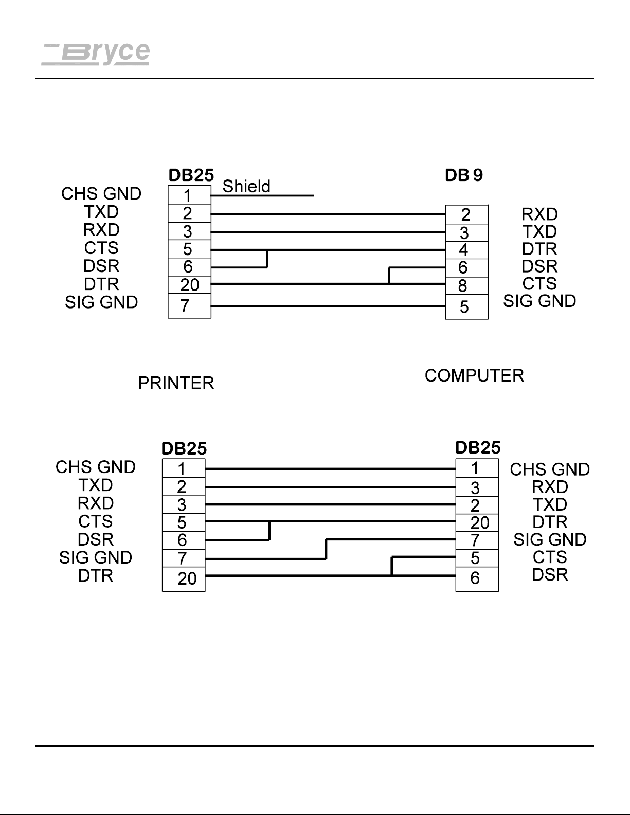
Appendix E Computer Interface Wiring Diagram
Serial Communication (RS - 232 C) connections for the Address Printer
Revision A 9K-L USERS MANUAL Section E - 1
P/N 90-00860-001
Page 99

Appendix F Printing with Software
Software Table of Contents
MICROSOFT WINDOWS™ APPLICATIONS SOFTWARE DRIVER INFORMATION ............................3
Software Interface sample: AccuZIP 6 for Windows................................................................4
Software Interface sample: Lotus Approach ver. 3.0 for Windows............................................6
Software interface sample: ARCLIST ver. 2.06 ..........................................................................8
Software interface sample: ARC TANGENT PROFESSIONAL MAIL ver. 2.05......................9
Software Interface sample: Bulk Mailer + 4.20i for Windows..................................................10
Software interface sample: DATAPERFECT ver 2.2................................................................12
Software Interface sample: dBASE IV ver 1.0 ..........................................................................13
Software interface sample: FILE EXPRESS ver. 5.1.................................................................14
Software interface sample: IBM FILING ASSISTANT............................................................16
Software Interface sample: Microsoft FoxPro 2.6 for Windows ...............................................17
Software interface sample: LOTUS 123 Release 3.1+ for DOS................................................23
Software interface sample: MailMiser ver 1.2...........................................................................24
Software interface sample: MULTIMATE................................................................................25
Software interface sample: MyMailList ver. 1.9.7.....................................................................26
Software Interface sample: Postalsoft Desktop Mailer ver. 5.0 for Windows...........................27
Software Interface sample: PreSort Pro by MCS version 2.4 for Windows..............................29
Software interface sample: RAPIDFILE....................................................................................31
Software interface sample: REFLEX ver. 2.0............................................................................32
Software interface sample: WORDPERFECT 6.0.....................................................................33
Software interface sample: WORDSTAR FOR DOS ver. 7.0..................................................34
POWER PRINT for the MACINTOSH .....................................................................................35
POWER PRINT for the MACINTOSH (Continued)................................................................36
Computer setup sample: IBM Mini's (System 34, 36, 38) & AS400.........................................37
Software interface sample: MICROSOFT WORD FOR WINDOWS ver. 2.0..........................38
Software interface sample: Word97 for Windows 95................................................................39
Revision A 9K-L USERS MANUAL Section F - 1
P/N 90-00860-001
Page 100

Appendix F Printing with Software
Software Setup
Generic Software Driver Information
Most software packages allow you to select or setup a printer driver. Use one of the
following printer drivers.
Dumb Printer
Generic Printer
Typewriter
Plain Vanilla
Teletype
TTYCRLF Printer
TTYCR Printer (This requires the Setup Menu CR = CR + LF option to be
turned on)
If none of these choices are available one of the following may work:
HP Laserjet Series II or any Laserjet II listed (excluding Postscript)
HP Laserjet 4
DOS Text Printer
Don't forget to set the MODE COMMAND!!!
Type the MODE command at the DOS prompt or add the MODE command to the
AUTOEXEC.BAT file. The AUTOEXEC.BAT will load the command when the
computer is first booted up.
Example:
When printing to the parallel port load MODE LPT1:,,P
When printing to the serial port load MODE COM1:9600,N,8,1,P
(NOTE: The printer ports or parameter settings may vary from the preceding
MODE command examples. If using DOS version 5.0, a ,,B may be substituted for
the ,,P)
Revision A 9K-L USERS MANUAL Section F - 2
P/N 90-00860-001
 Loading...