

Page 1
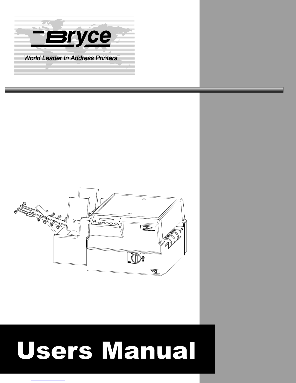
30K Addressing
Printer
Page 2

WARNING
WARNING: HIGH VOLTAGES ARE PRESENT BEHIND THE COVERS AND IN THE PAN ASSEMBLY.
Never remove the pan access cover assembly or rear cover assembly since there are no user serviceable parts
inside. The electrical and/or sensitive parts may only be serviced by an authorized Service Representative.
Important Safeguards :Read all instructions before attempting to operate this equipment.
To reduce the risk of fire and/or electric shock, do not attempt to disassemble this machine.
The machine is not intended for use in hazardous locations. Do not use in environments known to
contain flammable or explosive gases.
To prevent overheating, do not cover vent openings or use the machine over a radiator or heat register.
To reduce the risk of injury, refer all non-operator service functions to qualified service personnel.
Access only those operator designated areas of machine for jam clearing. All other areas of machine
requiring disassembly or removal of covers should only be accessed by qualified service personnel.
This machine cabinet serves to enclose hazardous parts. If the machine has been dropped or otherwise
had the cabinet stressed in any way, report it to your local service representative.
In the performance of operator service procedures, be certain the machine is unplugged from the wall.
Do not attempt to use this product in an unauthorized manner. To do so may expose you to mechanical
and / or electrical hazards.
Do not expose power cord to sharp points or edges.
To protect against shock, the power cord must only be plugged into a grounded receptacle. The ground
pin on the plug must never be removed.
The power cord should be routed so it cannot be walked upon.
Do not operate this machine with a damaged power cord or plug.
Unplug or otherwise disable this machine before cleaning.
Know how to turn off power in the work area, and to summon help in the event of an emergency.
Do not remove safety covers for cleaning, adjustments or repairs. Call your service representative.
Keep office supplies such as paper clips, staples, rubber bands, etc., away from machine.
Keep loose clothing ties, jewelry, and long hair away from moving parts of this machine.
Ink formulations for use in this machine are critical. Use only those specified.
Notice: Changes or modifications to this unit not expressly approved by the party responsible for
compliance could void the user’s authority to operate the equipment.
Treat every circuit as if it were live. Check first with a neon tester or a voltmeter.
Federal Communications Commission Compliance
"This device complies with Part 15 of the FCC Rules. Operation is subject to the following two conditions:
1). This device may not cause harmful interference, and
2). This device must accept any interference received, including interference that may cause
undesired operation.
Page 3
NOTE: This equipment has been tested and found to comply with FCC Rules Part 15 subpart B Class B for a digital
device. These limits are designed to provide reasonable protection against harmful interference in a residential installation. This
equipment generates, uses, and can radiate radio frequency energy and, if not installed and used in accordance with the
instructions, may cause harmful interference to radio communications. If this equipment does cause harmful interference to radio
or television reception, which can be determined by turning the equipment off and on, the user is encouraged to try to correct the
interference by one or more of the following measures:
Reorient or relocate the receiving antenna.
- Increase t he separation between the equipment and receiver.
- Connect the equipment into an outlet on a circuit different from that to which the receiver is connected.
- Consult the dealer or an experienced radio / TV technician for help.
Shielded cables must be used with this unit t o ensure compliance with the Class B FCC limits.
Canadian DOC Compliance.
"This Class B digital apparatus meets all requirements of the Canadian Interference-Causing Equipment Regulations.
Cet appareil numérique de la classe B respecte toutes les exigences du Règlement sur le matériel brouilleur du
Canada.
Caution
Danger of explosion if battery is incorrectly replaced. Replace only with the same or equivalent type recommended by the
manufacturer. Dispose of used batteries according to the manufacturer’s instructions.
VORSICHT
Explosionsgefahr bei unsachgemäßem Austausch der Batterie.
Ersatz nur durch denselben oder einen vom
Hersteller empfohlenen gleichwertigen Typ.
Entsorgung gebrauchter Batterien nach
Angaben des Herstellers.
ADVARSEL
Lithiumbatteri − Eksplosionsfare ved fejlagtig håndtering.
Udskiftning må kun ske med batteri af samme fabrikat og type.
Levér det brugte batteri tilbage tilleverandøren.
Notice
The information in this document is subject to change without notice. Bryce Office Systems makes no warranty of
any kind with regard to the material contained herein. Bryce Office Systems will not be liable for incidental or
consequential damages in connection with the furnishing, performance or use of this material.
Page 4

TABLE OF CONTENTS
FOREWORD
INTRODUCTION
PRINTER PARTICULARS Chapter 1
Configurations ...............................................................................................1 - 1
PARTS OF THE PRINTER Chapter 2
Printer Parts & Locations...............................................................................2 - 1
SETTING UP THE PRINTER Chapter 3
Choosing a Good Location for the Printer.........................................3 - 1
Removing Protective Materials .........................................................3 - 1
Connecting the Printer.......................................................................3 - 2
Connecting the Power Cord...............................................................3 - 2
Connecting to the Conveyer Port.......................................................3 - 3
POWER ON...................................................................................................3 - 4
Installing a Print Cartridge.................................................................3 - 5
Removing the Print Cartridge............................................................3 - 6
Preparing the Media...........................................................................3 - 7
Media Types ......................................................................................3 - 8
PRINTER TIPS Chapter 4
Finding the Right Height Adjustment for Media Thickness..............4 - 1
Adjusting the Entry Roller Assembly................................................4 - 2
Adjusting the Exit Idler Assemblies..................................................4 - 3
Synchronizing new Print Cartridges in the Print Head Assembly.....4 - 4
Vertically Synchronizing a Bank of Print Cartridges........................4 - 5
Horizontally Synchronizing a Bank of Print Cartridges....................4 - 7
Adjusting the Banks Apart.................................................................4 - 8
Adjusting the Banks Together ...........................................................4 - 9
Synchronizing 3 Print Head Assemblies ..........................................4 - 10
Moving the Wipers ............................................................................4 - 12
Prolonging the life of Print Cartridges...............................................4 - 13
Affects the Performance of the Printer ..............................................4 - 14
RUNNING WITH THE FEEDER ASSEMBLY Chapter 5
Setting up a feeder to work with the printer ......................................5 - 1
Feeder Parts and Locations................................................................5 - 2
Attaching the Bryce Feeder Assembly ..............................................5 - 3
Attaching the Feed Ramp Assembly..................................................5 - 3
Revision C 30K USERS MANUAL Section i - 1
P/N 90-00203-001
Page 5

TABLE OF CONTENTS
Setting the H-Block Assembly ..........................................................5 - 4
Setting the Sliding Fence...................................................................5 - 5
Setting the Media Support Wedge.....................................................5 - 5
Setting up the Wide Media Shafts .....................................................5 - 6
Setting up and using the Feed Ramp Extension ................................5 - 7
PRINTER MENU SYSTEM Chapter 6
FRONT PANEL CONTROLS AND LCD DISPLAY..................................6 - 1
What does the display show...............................................................6 - 2
MAIN MENU................................................................................................6 - 3
• 1. Address Layout.......................................................................6 - 3
• 2. Print Quality............................................................................6 - 4
• 3. Font.........................................................................................6 - 5
• 4. Barcode...................................................................................6 - 6
• 5. Address Recovery...................................................................6 - 6
• 6. Clear Counter..........................................................................6 - 7
• 7. Job Settings.............................................................................6 - 7
• 8. Conveyer Time........................................................................6 - 8
• 9. Image Overlay.........................................................................6 - 8
• 10. Purge Print Head...................................................................6 - 9
• 11. Reset Ink Count ....................................................................6 - 9
SETUP MENU...............................................................................................6 - 10
• 1. Stop On Feed Error.................................................................6 - 10
• 2. Feeder Signal ..........................................................................6 - 10
• 3. Lines Per Address...................................................................6 - 11
• 4. Line Termination ....................................................................6 - 12
• 5. Hex Dump Mode.....................................................................6 - 12
• 6. Language.................................................................................6 - 12
• 7. Transport Speed......................................................................6 - 13
• 8. Postal Bundle Break................................................................6 - 14
• 9. Pre-Purge ................................................................................6 - 15
• 10. Feed Gap................................................................................6 - 15
• 11. Rom Revision#......................................................................6 - 16
• 12. Print Head Size .....................................................................6 - 16
SERVICE MENU..........................................................................................6 - 17
• 1. Adjust Print.............................................................................6 - 17
• 2. Test System.............................................................................6 - 20
• 3. Test Display............................................................................6 - 20
TROUBLESHOOTING & DIAGNOSTICS Chapter 7
SYMPTOMS & SOLUTIONS..........................................................7 - 1
SYMPTOMS & SOLUTIONS when using the Bryce Feeder...........7 - 7
Revision C 30K USERS MANUAL Section i - 2
P/N 90-00203-001
Page 6

TABLE OF CONTENTS
CLEANING AND MAINTAINING THE PRINTER Chapter 8
PREVENTATIVE MAINTENANCE ...........................................................8 - 1
Cleaning the Print Cartridges.............................................................8 - 1
Cleaning the Photo Sensor Assembly................................................8 - 2
Cleaning the Wipers...........................................................................8 - 2
Cleaning the Exit Idler Roller & Entry Rollers .................................8 - 2
Cleaning the Transport Belts and Floor Assembly............................8 - 2
Cleaning the Tires on the Feeder Assembly......................................8 - 3
Replacing the Tires on the Upper & Lower Feeder Shaft
Assemblies.........................................................................................8 - 3
PRINTER MENUS APPENDIX A
30K MAIN MENU.......................................................................................A - 1
30K SETUP MENU......................................................................................A - 3
30K SERVICE MENU.................................................................................A - 5
HEX CHART APPENDIX B
HEX CHART.................................................................................................B - 1
PRINTER CONTROL COMMANDS APPENDIX C
PCL COMMAND CODES............................................................................C - 1
CHARACTER SET APPENDIX D
30K CHARACTER SET ..............................................................................D - 1
COMPUTER INTERFACE WIRING DIAGRAM APPENDIX E
PARALLEL & T-11 CABLE WIRING DIAGRAM....................................E - 1
PRINTING WITH SOFTWARE APPENDIX F
SOFTWARE TABLE OF CONTENTS........................................................F - 1
SOFTWARE SETUP.....................................................................................F - 2
TECHNICAL SPECIFICATIONS APPENDIX G
US MAIL REQUIREMENTS APPENDIX H
DELIVERY POINT BARCODE...................................................................H - 1
PLANET CODE BARCODE ........................................................................H - 3
Revision C 30K USERS MANUAL Section i - 3
P/N 90-00203-001
Page 7

TABLE OF CONTENTS
EAN / UCC REQUIREMENTS APPENDIX I
GLOSSARY APPENDIX J
ORDERING INFORMATION APPENDIX K
OPTIONS & SUPPLIES................................................................................K - 1
Revision C 30K USERS MANUAL Section i - 4
P/N 90-00203-001
Page 8

Introduction
This manual is for the person who is new to the Bryce 30K Address
Printer and needs step by step instructions to setup and operate the
printer.
The appendix at the end of the manual has information for those
who are familiar with the 30K printer and simply want a quick
reference or want more specific technical information on the 30K
printer.
Section 1 – Printer Particulars
Configurations available for the printer.
Section 2 –Parts of the Printer
Illustrations showing the location of printer components.
Section 3 – Setting up the Printer
Describes the basics of how to setup and install the components of
the printer for the first time.
Section 4 –Printer Tips
Additional adjustments and instructions to fine tune the printer.
Who is this
manual for?
Section 5 – Running with the Feeder Assembly
Outlines the prerequisites for setting up a non-Bryce feeder with the
printer. Also included are step by step instructions to assemble and
install the 30K feeder.
Section 6 – Printer Menu System
Explains each of the menu options of the address printer.
Section 7- Troubleshooting and Diagnostics
A list of possible problems you may encounter when operating the
printer and their solutions.
Section 8 – Cleaning and Maintaining the Printer
General maintenance steps to keep the printer clean and functioning
properly.
Appendices
The appendices include a quick reference table for the 30K menus, a
listing of the PCL commands the printer recognizes, a hex chart to
help work through a HEX dump, and references of setting up the
most popular software to work with the printer. The final section
has a list of supplies available for your printer.
Revision C 30K USERS MANUAL
P/N 90-00203-001
1
Page 9
Printer Particulars
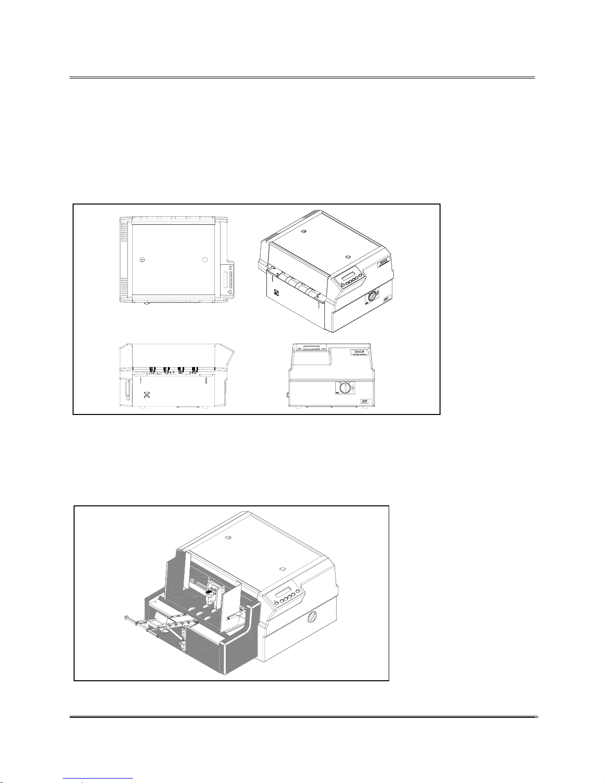
The printer is available in two configurations, as described in
the following examples.
· Bryce 30K.
The Printer comes with two banks of black Print Cartridges
for printing and 16 MB of RAM.
Configurations
· Bryce 30K with Feeder.
The Printer comes with a automatic Feeder Assembly that has
a 7 1/2 ” stack capacity, and a standard tray and tray
extension.
Revision C 30K USERS MANUAL Section 1 -
P/N 90-00203-001
1
Page 10
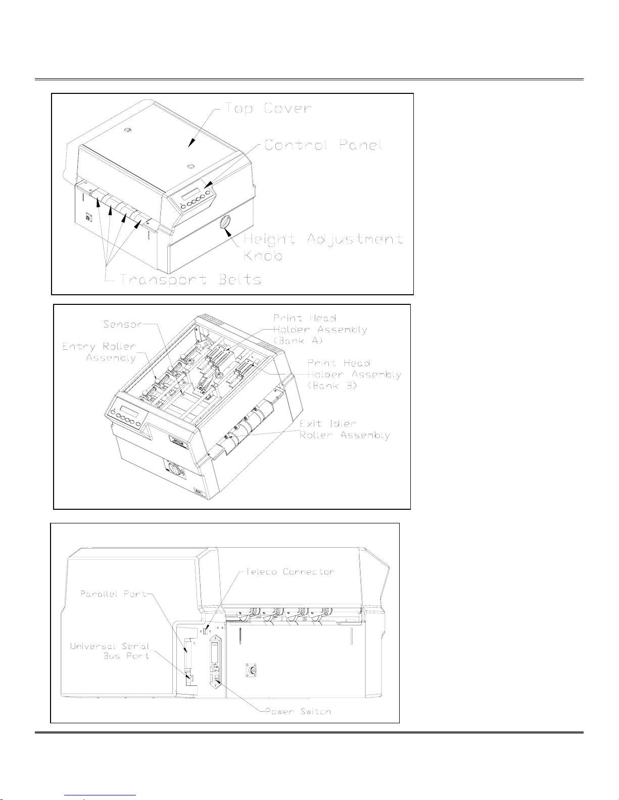
Parts of the Printer
Printer
Parts &
Locations
Revision C 30K USERS MANUAL Section 2 - 1
P/N 90-00203-001
Page 11
Setting up the Printer
The following environmental considerations must be kept in
mind when selecting a location for the Address Printer. Doing
otherwise may affect the operation and performance of the
Address Printer.
1. Place the printer close enough to the computer for the
parallel cable to reach.
2. Place the printer on a flat, stable surface.
3. Use a grounded, dedicated outlet for the printer only.
Note: Do not use an adapter plug.
4. Avoid locations near direct sunlight, excessive heat,
high humidity, moisture, or dust.
5. Keep the entire system away from large motors or
other appliances that might disturb the power supply or
create potential interference.
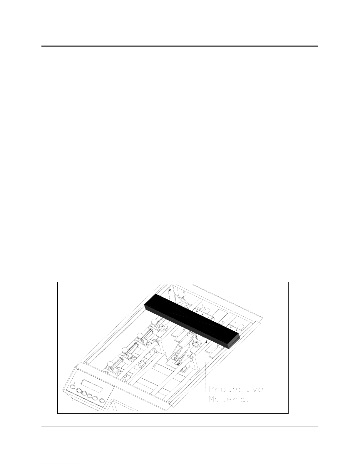
The printer is protected during shipping with corrugated
cardboard around the Head Print Carriages.
1. Remove the Top Cover to gain access to the inside of
the printer.
Choosing a
Good
Location for
the Printer
Note: AB switches are
not recommended for
operation with this
printer.
Removing
Protective
Materials
2. Remove the styro-foam protective insert.
Revision C 30K USERS MANUAL Section 3 -
P/N 90-00203-001
1
Page 12
Setting up the Printer
Connecting
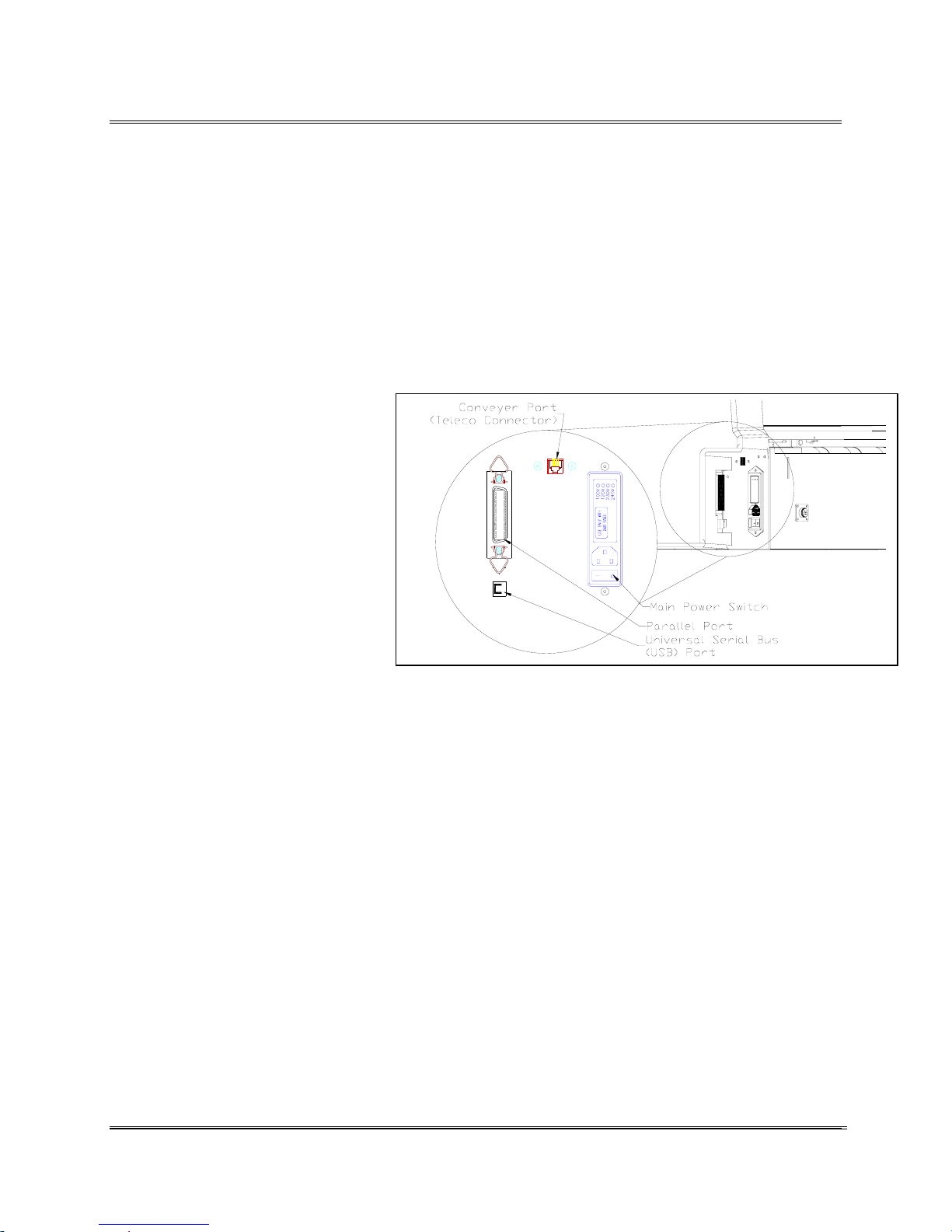
Connect the Address Printer to the parallel port of the
computer. The Parallel port is located on the rear of the printer
near the power switch.
To connect printer to the computer do the following steps.
1. Align the male end of the parallel cable or female end
of the serial cable connector to the port on the printer.
Push the cable connector completely in.
2. Secure the cable in place.
Use the two wire clips
located on each side of the
Parallel connector to snap
into the tabs on the
connector.
3. Align the other end of the
cable to the connector on
the computer and push into
the port.
the Printer
Note: AB switches are
not recommended for
operation with this
printer.
4. Secure the cable in place.
Use the thumb screws on
the connector to screw into the hex jack screws on the
computer.
The power cord receptacle is located on the Electrical Bracket
Assembly along with the ON/OFF (I/O) power switch.
Connect the power cord to a grounded outlet. Avoid using
outlets that are controlled by wall switches and are shared
with other equipment.
1. Make certain the ON/OFF (I/O) power switch is OFF
(O). Push the female end of the power cord into the
power receptacle.
2. Plug the other end into a grounded power outlet.
Connecting
the Power
Cord
Revision C 30K USERS MANUAL Section 3 -
P/N 90-00203-001
2
Page 13
Setting up the Printer
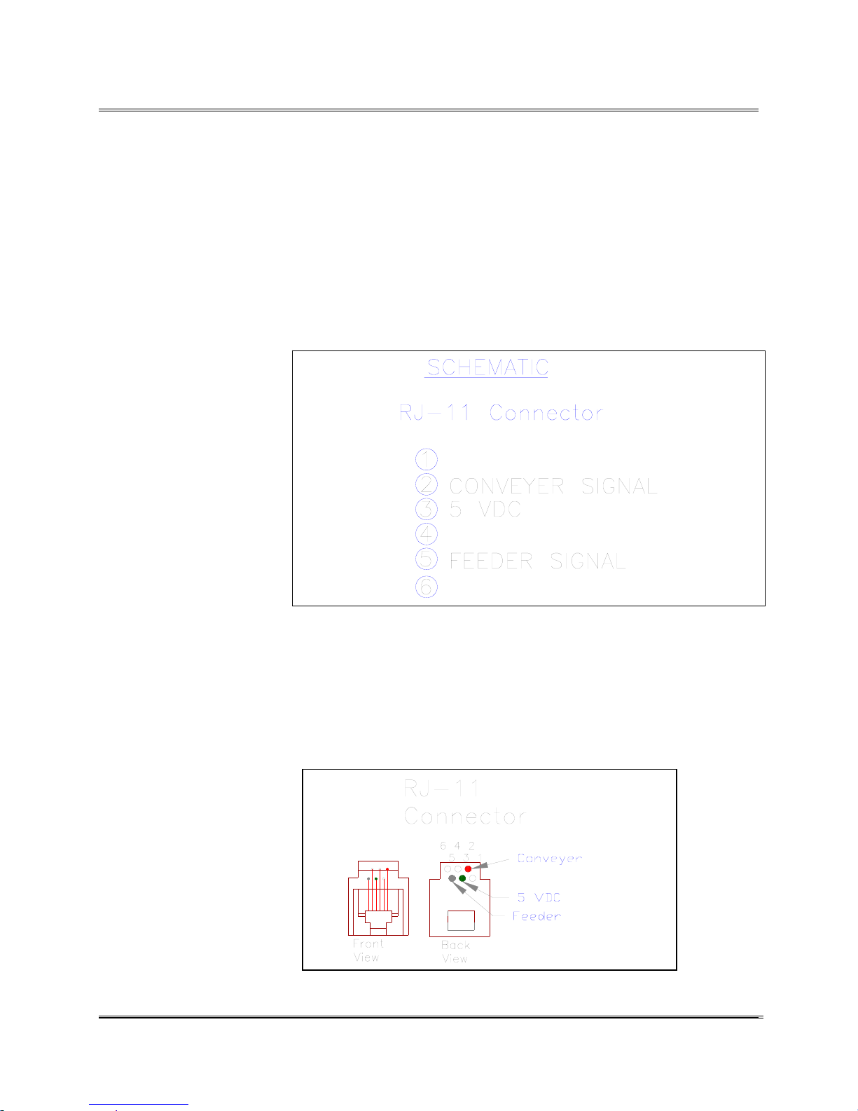
The Conveyer Port can maximize the operation of a conveyer
when used with the printer. Settings used for configuring the
port for a conveyer are found in the Main Menu.
The port is designed to connect to the Bryce Pulse Box
(optional), then the box to the conveyer. With the Bryce Pulse
Box connected the conveyer will only operate while the
printer is printing addresses. The printer can control the
singling of the media onto the conveyer by fine tuning the
conveyer speed adjustment in the Main Menu of the printer.
These options will allow the maximum number of pieces of
media to be fed onto the
conveyor and the longest
drying time before the
conveyer stacks the
media.
Modifications to the
amount of time the
conveyer continues to run
after printing a record is
done through the
CONVEYER TIME
option in the MAIN
MENU. See Section
Conveyer Time for more
information.
Connecting to
the Conveyer
Port: Teleco
Connector
The following Schematic and Diagram of the Teleco
Connector port show where the microprocessor signals to
control the conveyer is found. Use the following Schematic to
get the conveyer signal.
Revision C 30K USERS MANUAL Section 3 -
P/N 90-00203-001
3
Page 14
Setting up the Printer
The power cord is plugged in, the printer is connected to the
computer. Now you can turn the power on.
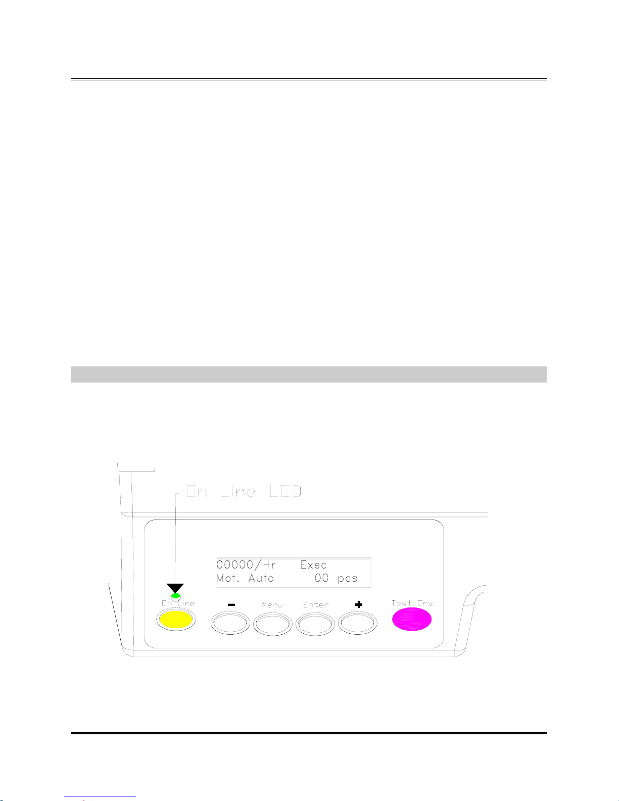
· Press on the printers' ON/OFF (I/O) power
switch. The switch is located on the side of the
printer next to the line cord receptacle. Press on
the symbol "I" (ON) position. The printer LCD
menu will display the initializing phrase
PRINTER STARTING 1 then PRINTER
STARTING 2 and printer will automatically go
ON LINE.
The Addressing Printer uses up to six black Print Cartridges
for printing. To install the cartridge, do the following:
· Verify the LED above the ON LINE button is lit. The
LED is either unlit for OFF LINE or lit for ON LINE.
Power On
.
Revision C 30K USERS MANUAL Section 3 - 4
P/N 90-00203-001
Page 15
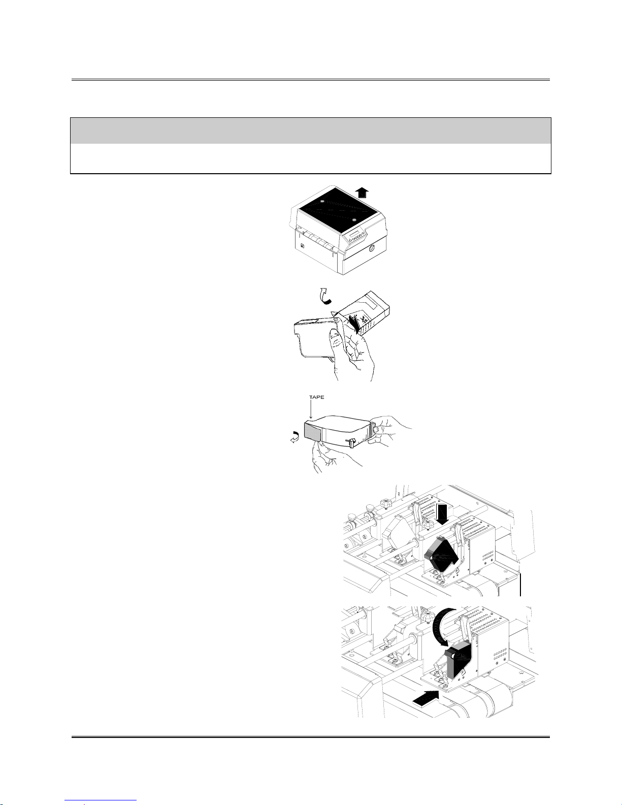
Setting up the Printer
CAUTION
The ink in the print cartridge may be harmful if swallowed. Keep new and used cartridges
out of reach of children. Discard empty print cartridges in the proper manner.
1. Remove the top cover.
2. Remove the Cartridge
from the shipping
container by peeling top cover off.
Be careful not to touch the copper
ribbon.
3. Gently remove both pieces of
tape covering the ink nozzles on
the print cartridge. Be careful not
to touch the copper nozzles.
Installing a
Print
Cartridge
Note: The 30K was
designed to use a
51645 style print
cartridge or HP
51645A Ink
Reservoir System
HP
.
4. Raise the latch all the way up on the Head
Print Assembly. Hold cartridge from the
notched handle on top of the cartridge.
Gently insert cartridge down at
approximately a 45 degree angle into the
cradle.
5. Push down on the ink cartridge until it is
seated on the bottom of the Head Print
Assembly. Push and rock the ink cartridge
forward to stand ink cartridge up. Press
down blue latch to lock ink cartridge in
place.
Revision C 30K USERS MANUAL Section 3 - 5
P/N 90-00203-001
Page 16
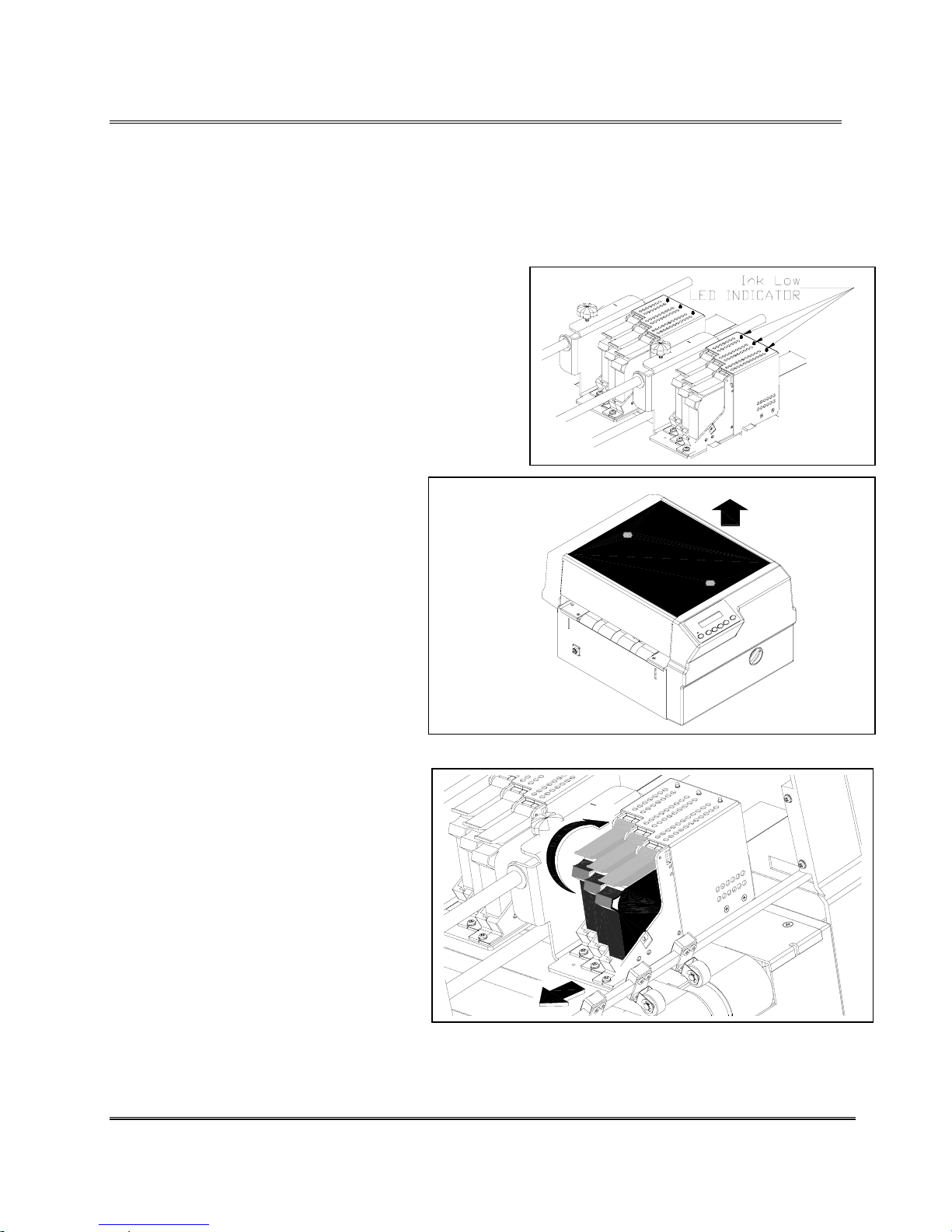
Setting up the Printer
When the Ink Low LED indicator is blinking the Print
Cartridges are nearly empty and have to be changed soon. Use
the following steps to remove used or damaged Print
Cartridges.
Removing
the Print
Cartridge
1. Remove the Top Cover.
2. Grasp the latch on top. Lift up
on the latch. The cartridge will
“pop” loose.
2. Grasp the handle on the ink
cartridge and lift the print
cartridge out of the cradle.
Note: Reset the Ink
Count in the Main
Menu after replacing a
Ink Cartridge.
Revision C 30K USERS MANUAL Section 3 -
P/N 90-00203-001
6
Page 17
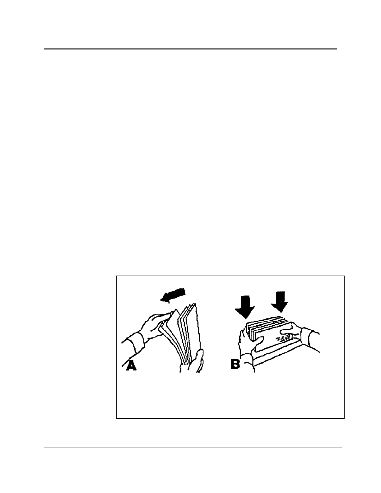
Setting up the Printer
Make certain all the necessary components of the printer are
installed:
• Is the printer plugged into a power outlet?
• Does the printer have at least three black print
cartridges installed in one of the Banks?
• Is the printer connected to the computer?
Now that the printer is installed the setup or adjustments to the
printer need to be done for it to work with the media. To avoid
problems of misfeeding and jams the media must also be made
ready for the printer.
Use the following steps to make the media ready for printing:
1. Take a manageable pile of media and while holding
them (as shown below in reference A), "fan" all sides
of the media to make sure that each piece of media is
free from one another.
2. Square the pile against the tabletop, assuring a square
pile on all sides. (Reference B) This will also allow
media to settle toward the bottom of a stuffed envelope
and will increase consistency in the print and increase
the feeding capabilities of the feeder.
Preparing
the Media
Note: Maximum
thickness is 0.5”(1.27
cm).
Revision C 30K USERS MANUAL Section 3 -
P/N 90-00203-001
Fan All Sides of Media Square Media
7
Page 18

Setting up the Printer
The printer is designed to print on a variety of media with
various finishes and coatings. The sharpness of the print
quality will vary with different media types. Depending on
how absorbent the media is, as well as, other qualities, the best
results can be achieved using white wove bonded stock. The
printing quality will be less sharp on tyvek, recycled and
glossy media.
The types of media the printer is able to use is:
• Envelopes: should be stacked to feed with the left
or right edge first.
• Booklets: should be stacked to feed with the sealed
edge leading or stacked with the sealed edge placed
to feed first.
• Catalogs: should be stacked to feed with the sealed
edge leading or stacked with the sealed edge placed
to feed first.
• Postcards: must be 3.5” (88.9 mm) x 5” (127 mm)
or larger.
Media
Types
• Self-Mailers: may be folded in half or “C” or “Z”.
The media must be tabbed.
• Paper: may consist of 16 to 80lb of uncoated to
coated stock. The maximum width and height is
specified in Appendix G.
All folded material and catalogs must be tabbed as per postal
regulations.
The paper types that can be used are:
• White wove
• Bond Paper
• Recycled Paper
• Coated Paper
• Card Stock
• Brown Kraft
• Manila
Revision C 30K USERS MANUAL Section 3 -
P/N 90-00203-001
8
Page 19
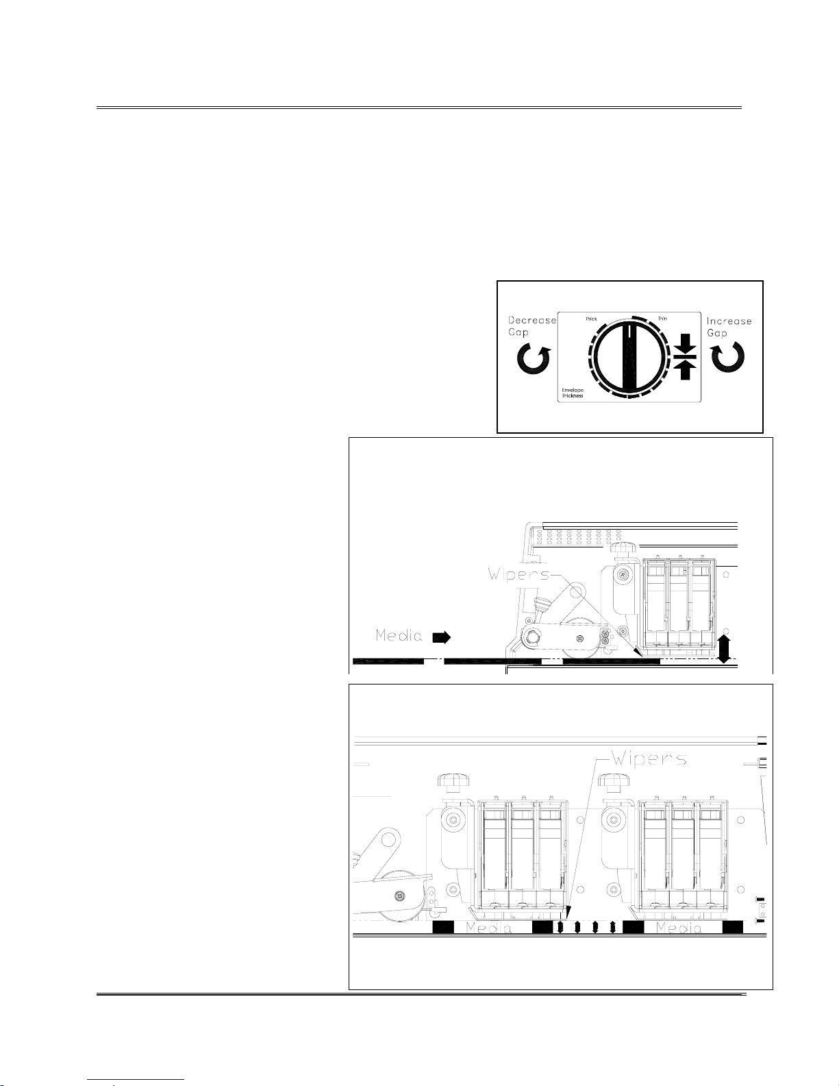
Printer Tips
A
w
Different sizes and types of media call for unique settings of
the Print Head Assemblies. To accommodate different sizes of
media the Print Head Assemblies have to be raised or lowered
until they touch the top of the media. Enough pressure has to
be applied by the metal wipers underneath the Print Head
Assemblies to keep the media from moving around beneath
the Print Cartridges while printing. Use the following steps as
a general guideline for most types of media.
1. Turn the Envelope Thickness Knob to raise the Print
Head Assemblies.
2. Insert a piece of the media beneath the Print Head
Assemblies.
3. Lower the Print Head
Lower towards media.
Assemblies down to just touch
the media and create a little
resistance when it is removed.
Finding the Right
Height
Adjustment for
Media Thickness
4. Press the [Test Env.] button to
print a test message and check
the quality of the print.
Note: The Print Head
ssemblies are to low
hen the print looks
smeared or clumped
together.
Set to top edge of Media
Revision C 30K USERS MANUAL Section 4 -
P/N 90-00203-001
1
Page 20
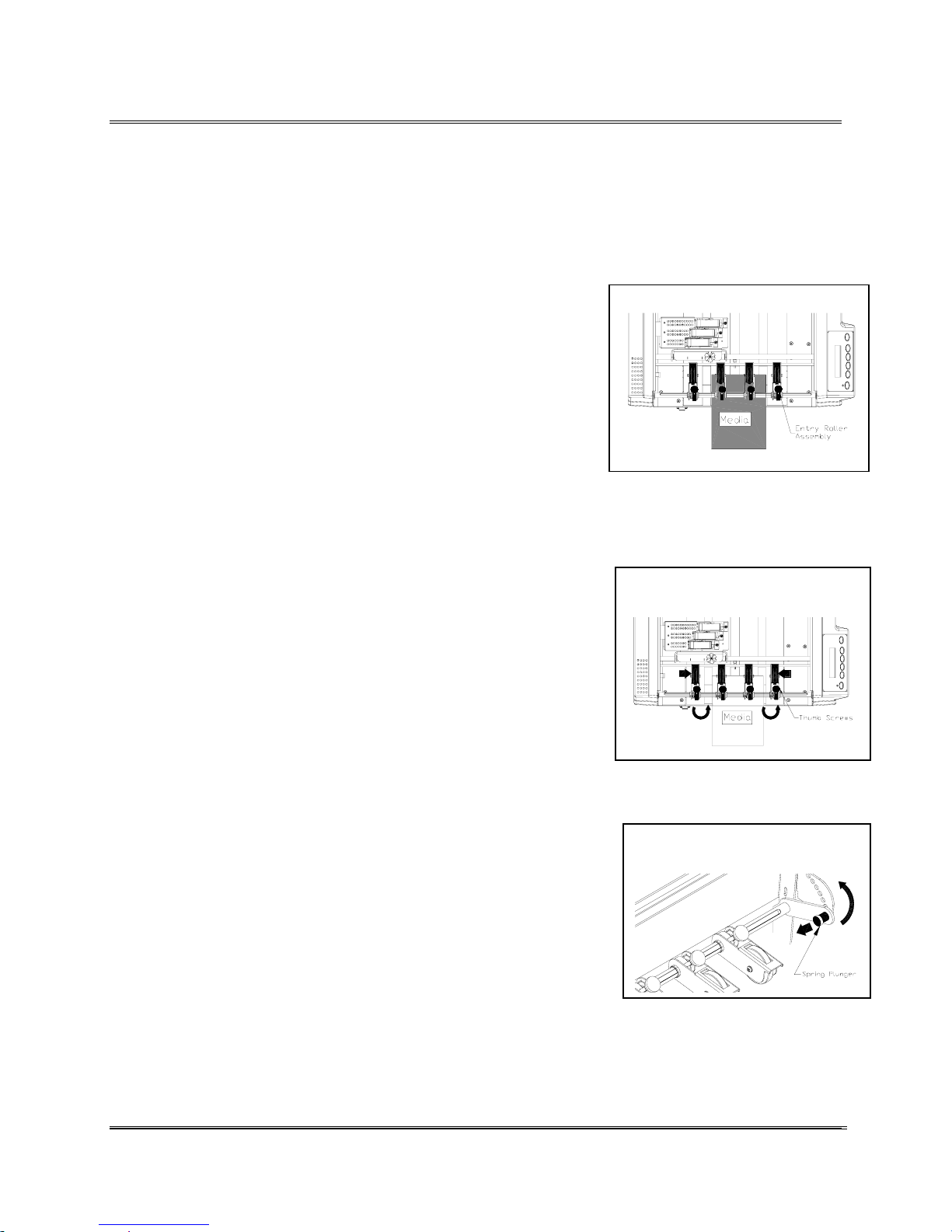
Printer Tips
The Entry Rollers keep the media pressed onto the Transport
Belts until it again gets trapped beneath the wipers of the Print
Head Assemblies.
1. Remove the Top Cover from the printer to gain access
to the inside.
2. Insert a piece of the media into the printer. Push it
beneath the Entry Rollers in the same location as the
feeder will send it.
3. Pull the Spring Plunger out to unlock the Index Wheel.
4. Raise the Index Wheel up to the top hole to lessen the
tension on the Entry Roller Assemblies and release the
plunger to secure the wheel in place.
5. Turn the Thumb Screw to release the Entry Roller
Assembly to reposition it on the shaft.
Adjusting the
Entry Roller
Assembly
Push the media in the printer.
Move the Entry Rollers onto
the media.
6. Lift and slide the Entry Roller Assemblies onto the
piece of media. Move any Entry Rollers near the sides
of the media further in on the media or push them out
of the way. Note: Rollers running on the edges of the
media may catch the edge and twist the media. Also,
locate the rollers on top of a Transport Belt.
Pull Spring Plunger out to
unlock.
7. Turn the Thumb Screw to secure Entry Roller
Assembly in place. Note: Check that the Thumb Screw
goes back into the slot in the shaft.
8. Pull the Spring Plunger out and lower the Index Wheel
to put the tension back on the Entry Rollers. Note:
Adjust the spring tension on the Entry Rollers by
moving the Index Wheel up or down to accommodate
different types of media.
Revision C 30K USERS MANUAL Section 4 -
P/N 90-00203-001
2
Page 21
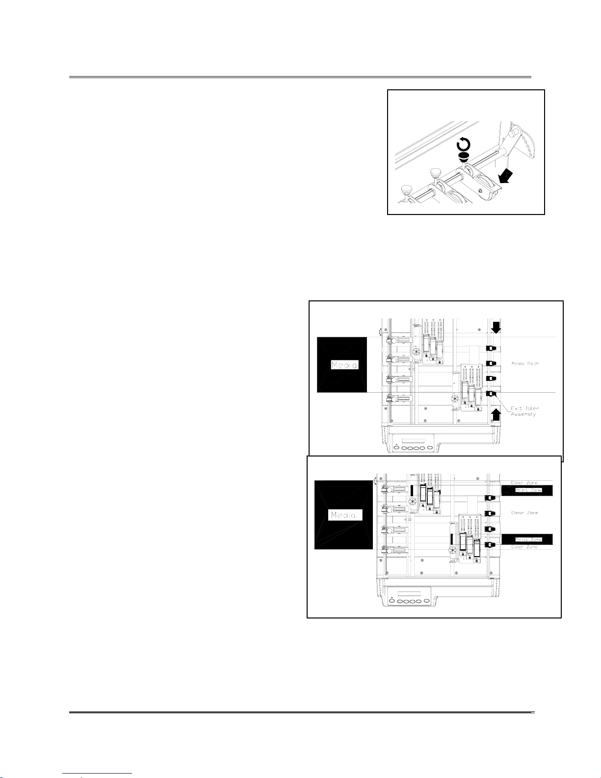
Printer Tips
9. Remove the piece of media and perform a test run to
check the position of the Entry Rollers on the media
during operation of the printer.
10. Replace the Top Cover to the printer.
The Exit Idler Assemblies keep the media from twisting or
moving around while it is still in the printer. For the Exit Idler
Assemblies to be effective they must be moved into the path
of the media and yet be in a clear zone (non printing area of
the media). If any of the rollers come into contact with the
printing they will act as a brush with paint and smear the print.
1. Remove the Top Cover to gain access to
Slide Exit Idlers into path of media.
the inside of the printer.
2. Slide the Exit Idler Assemblies to mirror
the arrangement of the Entry Roller
Assemblies. If the Entry Rollers are
properly set the Exit Idler Assemblies
are also in the path where the media will
travel trough the printer.
Turn Thumb Screw to move
Entry Roller Assembly
Adjusting the
Exit Idler
Assemblies
3. Locate the labels that indicate the Print
Slide Exit Idlers out of Print Zone.
Zone on each of the Print Head
Assemblies. Slide those Exit Idler
Assemblies that are in the path where
the ink is being sprayed to a clear zone
on the piece. Note: Run the printer to
test where the media will travel and to
check the location of print on the piece.
4. Replace the Top Cover to the printer.
Revision C 30K USERS MANUAL Section 4 -
P/N 90-00203-001
3
Page 22
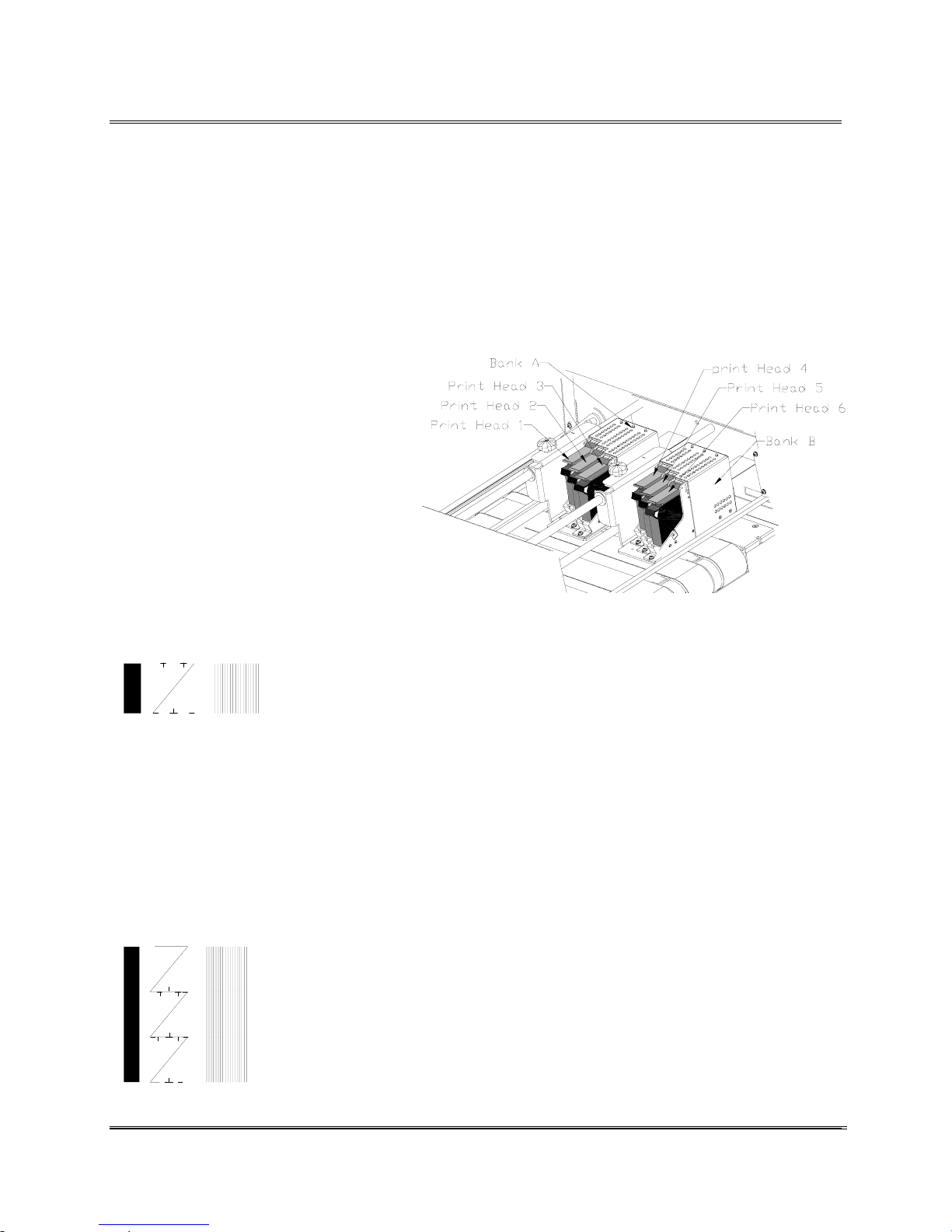
Printer Tips
A
A
w
Each bank of three Print Cartridges has to be synchronized to
print graphics, scaleable fonts or to justify the left edge of
print. If the Print Cartridges are not synchronized anything
that requires two or three Print Cartridges to line up a left edge
or to print next to each other may print to the left of one
another or on top of each other. When installing a new print
cartridge or cartridges into a 3 Print Head Assembly it may be
necessary to realign it with the other print cartridges.
Synchronizing the print cartridges in
the Print Head Assemblies is
accomplished using the Service
Menu option Adjust Print.
The following procedures will refer
to the left 3 Print Head Assembly as
Bank A, and the right 3 Print Head
Assembly as Bank B. Synchronize
each Bank of Print Cartridges by
aligning the Test Pattern that is
printed by each of the Print
Cartridges. Each Print Cartridge will
print a Test Pattern like the one
below.
Synchronizing
new Print
Cartridges in
the Print Head
Assembly
Head 2 Bank
Each carriage uses the leftmost Print Cartridge of the three to
synchronize the other two Print Cartridges. Counting from left
to right, the leftmost Print Cartridge in Bank A is referred to
as Head 1 and the leftmost Print Cartridge for Bank B is
referred to as Head 4.
The Test Pattern for a bank of Print Cartridges should look
like the following example when all three print cartridges are
synchronized.
Head 1 B ank A
Head 2 B ank A
Head 3 B an k
Note: Have several
pieces of media to use
hen synchronizing
the Print Cartridges.
Revision C 30K USERS MANUAL Section 4 -
P/N 90-00203-001
4
Page 23

Printer Tips
A
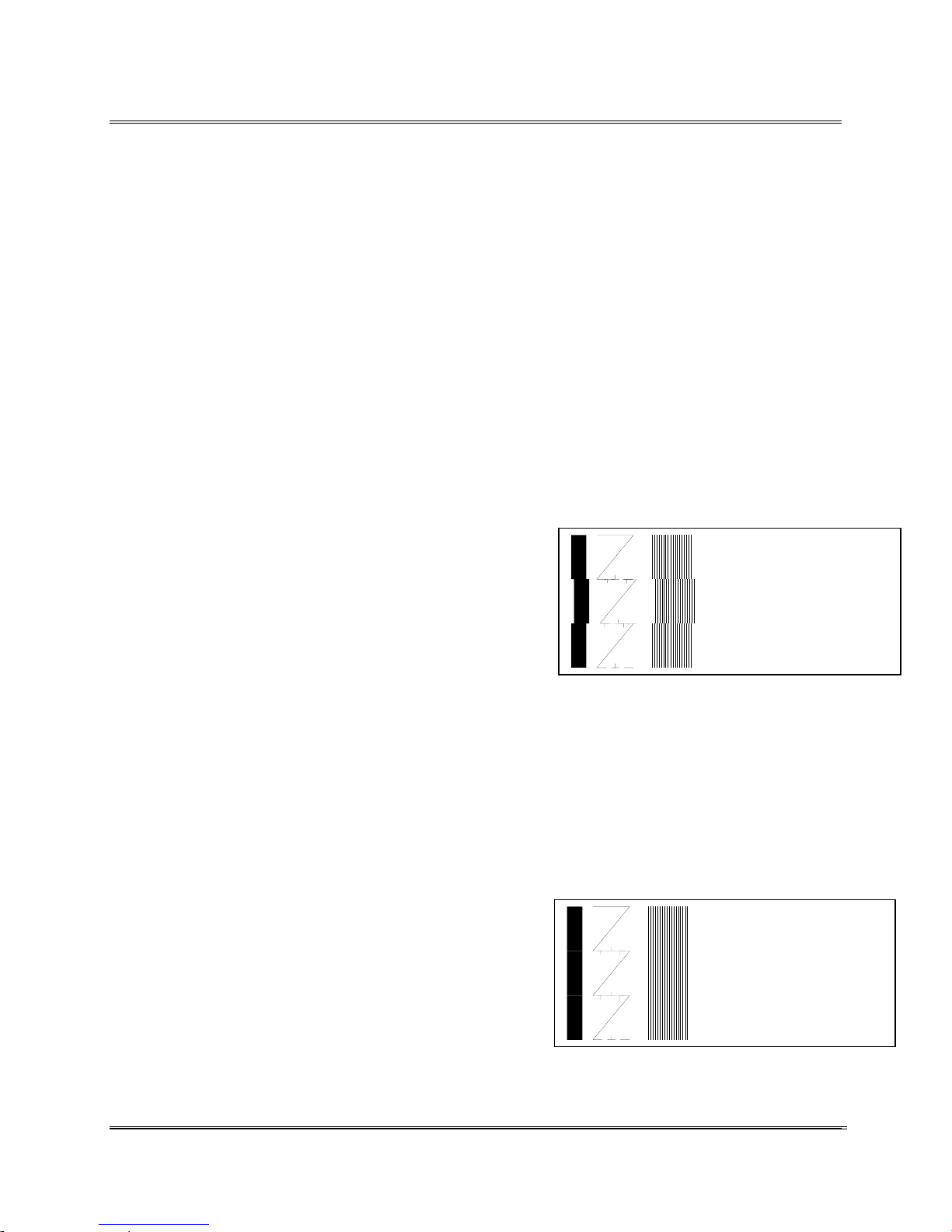
When lines of print start to run on top of each other the Print
Cartridges have to be synchronized vertically. Perform a
Vertical adjustment whenever the center of the Test Pattern
isn’t a solid crooked line. Work down from Head 1 on Bank A
or Head 4 on Bank B.
The following steps are an example of how to synchronize
Print Cartridges for Bank A. The same steps are taken for
vertically synchronizing Bank B.
Example:
In the example below the crooked line in the center indicates
Print Cartridge #3 has to have the printer perform a vertical
print adjustment.
Use the following steps to adjust Print Cartridge #3:
• Accessing the menu can only be accomplished in the
OFF LINE mode.
• When in ON LINE mode press the [On Line] button.
Once OFF LINE the service menus are accessible.
Press and hold down the [Menu] and [-] (Minus)
button simultaneously until SERVICE MENU appears
on the LCD display (in about two seconds).
Vertically
Synchronizing
a Bank of
Print
Cartridges
• Press the [+] plus or
through the Service Menu options until the 1. ADJUST
PRINT option is displayed on the LCD panel.
• Press the [Enter] button to select this option.
• Now print out a Test Pattern by pressing the [Test
Env] button. The printer will print a Test Pattern like
the following example:
[ - ] minus buttons to scroll
Head 1 Bank A
Head 2 Bank A
Head 3 Bank
Revision C 30K USERS MANUAL Section 4 -
P/N 90-00203-001
5
Page 24
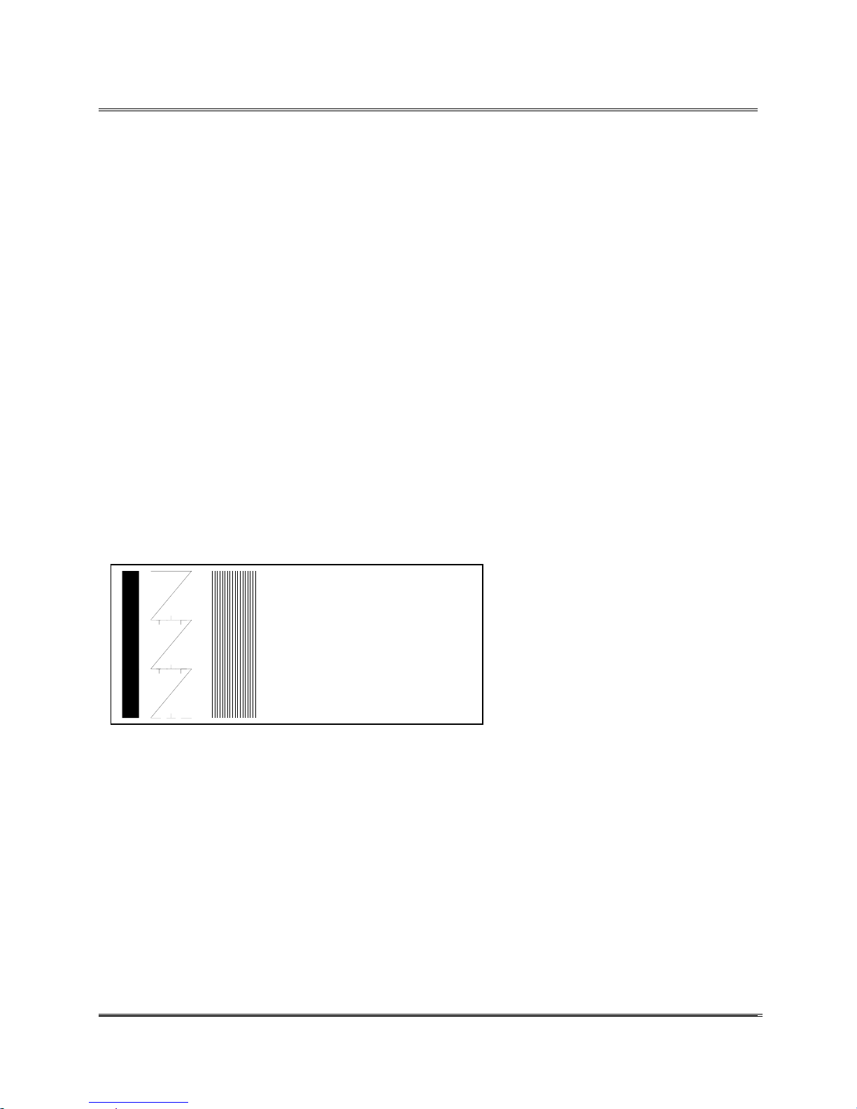
Printer Tips
A
A
A
The example shows Print Cartridge #3 is to high.
• Press the [+] plus or
through the Adjust Print menu options until the HEAD
3 UP DOWN option is displayed on the LCD panel.
• Press the [Enter] button to select this option.
• Press the [+] plus (UP) button to increment the
horizontal line value on the LCD display.
• Press the[ - ] minus (DOWN) button to decrease the
horizontal line value on the LCD display.
• Press the [Enter] button to select the desired value. An
Asterisk (*) will appear in front of the new selection.
• Press the [Test Env] button to print another Test
Pattern. This time the Test Pattern is printed using the
entered selection. The pattern printed should look like
the following example:
[ - ] minus buttons to scroll
Head 1 Ban k
Head 2 Ban k
Head 3 Ban k
When the correct numeral is selected the center test pattern
will be one long crooked line.
• Press the [Menu] button several times to back out of
the Service Menu.
• Press the [On Line] button; now the printer is ready
for use.
Revision C 30K USERS MANUAL Section 4 -
P/N 90-00203-001
6
Page 25
Printer Tips
A
A
A
A
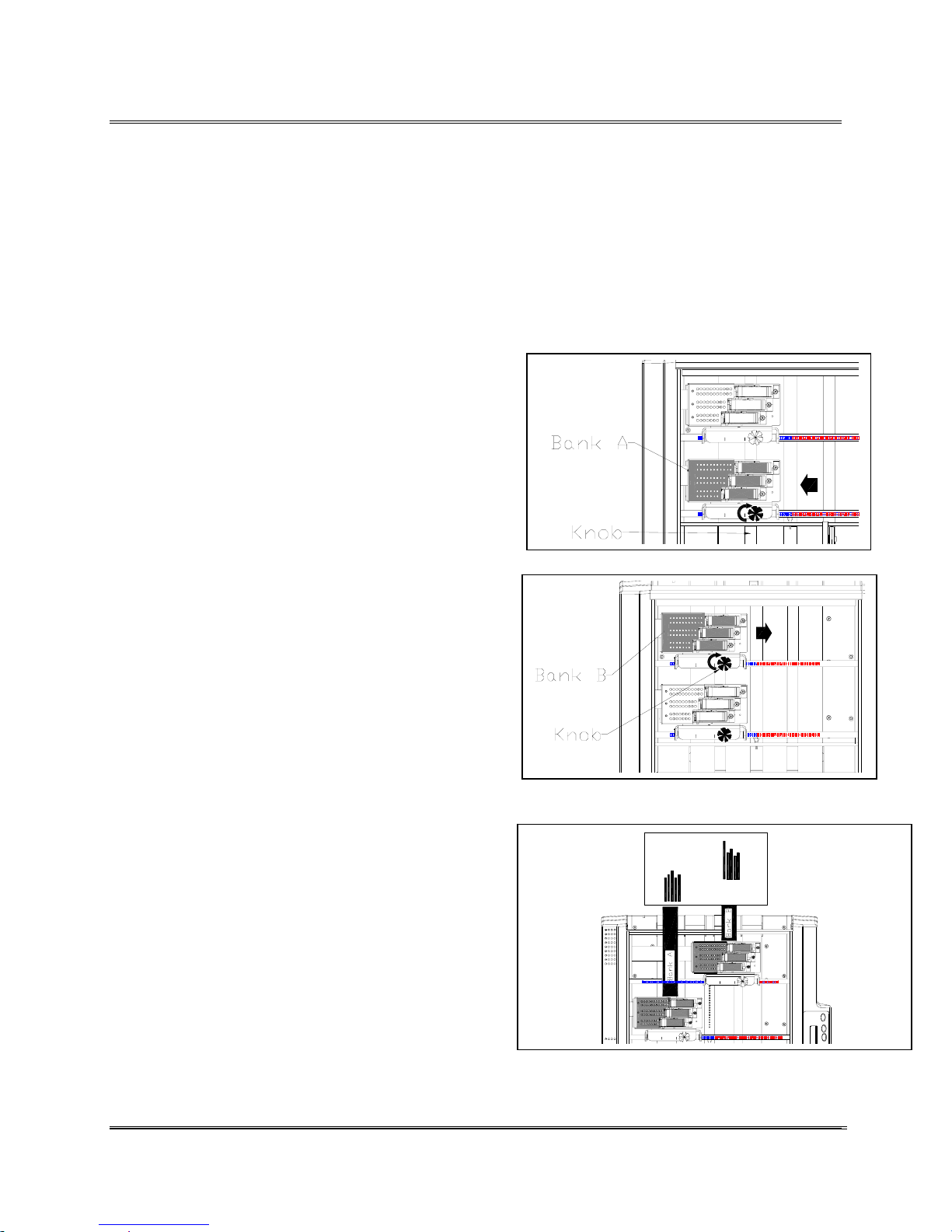
When a line of print is split apart or the left edge of a block of
lines don’t line up with the left edge of the other lines the Print
Cartridges have to be synchronized horizontally. Perform a
Horizontal adjustment whenever the large solid line and the
set of 18 thin vertical lines do not form long vertical lines for
the whole bank of Print Cartridges.
The following steps are an example of how to synchronize
Print Cartridges for Bank A. The same steps are taken for
horizontally synchronizing Bank B and any extra banks of
Print Cartridges.
Example:
In the example below the large vertical line on the left and 18
thin vertical lines indicate Print Cartridge #2 has to have the
printer perform a horizontal Print Adjustment.
Use the following steps to adjust Print Cartridge #2:
• Access the ADJUST PRINT menu. See example
in Vertically Synchronizing a Bank of Print
Cartridges.
• Print out a Test Pattern by pressing the [Test
Env] button. The printer will print a test pattern
like the following example:
Horizontally
Synchronizing a
Bank of Print
Cartridges
Head 1 B ank A
Head 2 Bank
Head 3 B ank A
The example shows Print Cartridge #2 is to far to the right.
• Scroll to the menu option HEAD 2 SIDE TO SIDE and
select the option.
• Press the [+] plus
horizontal line value on the LCD display.
• Press the [Enter] button to select the desired
value. An Asterisk (*) will appear in front of the
new selection.
(LEFT) button to increment the
Head 1 Bank
Head 2 Bank
• Press the [Test Env] button to print another test
pattern. This time the test pattern is printed using
the entered selection. The pattern printed should
look like the example to the right.
Revision C 30K USERS MANUAL Section 4 -
P/N 90-00203-001
Head 3 Bank
7
Page 26
Printer Tips
When the correct numeral is selected the large line and the set
of 18 vertical lines form long vertical lines down the entire
Bank A of Print Heads.
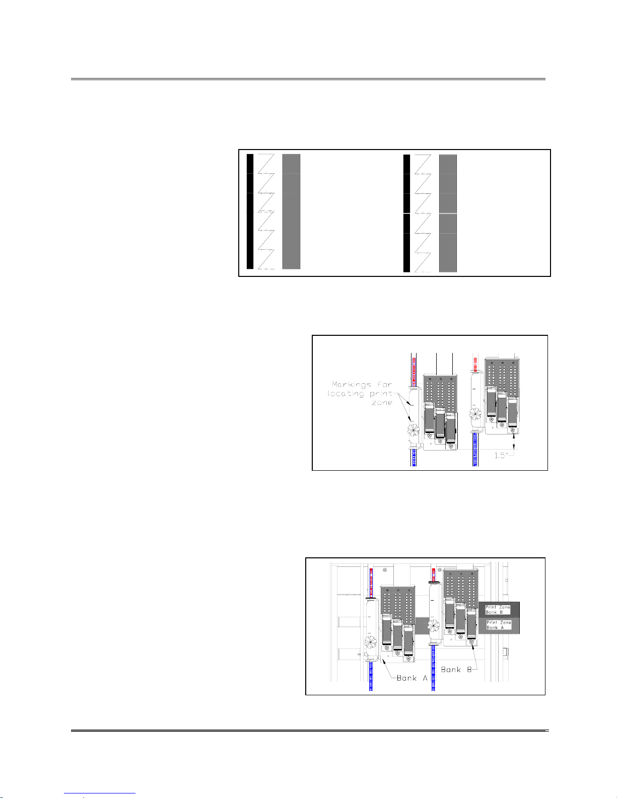
Use the two Banks to print a return address and indicia on the
top of a piece with the addressee’s on the bottom with a USPS
barcode printed on the bottom. Or combine to two banks
together for single large block graphic with the address added
in.
Example: Use the following steps to adjust the 3
Print Head Assemblies apart.
1. Remove the Cover from the printer.
2. Loosen the knob on top of the bracket that
secures Bank A.
Adjusting the
Banks Apart
3. Move Bank A to the top of the piece for
return address and indicia.
4. Loosen the knob on top of the bracket that
secures Bank B.
5. Position the Bank near the middle of the
piece.
6. Move the Exit Rollers out of the area where Bank A
and Bank B are printing on the media. If the
Exit Rollers contact any printed information
on the media they will act as a brush with
paint and smear the print. Use the scale on
the shafts to help position the Banks.
7. Print out the Adjust Print test message. The
test shows the area where the banks will
print. Check if any of the exit rollers run
over the top of the print, move the rollers
over to a clear zone (non printing area of the
media) before continuing.
Revision C 30K USERS MANUAL Section 4 -
P/N 90-00203-001
8
Page 27
Printer Tips
A
A
A
w
The two Banks of print cartridges can be combined and used
as one large block of print heads. This is best done for large
fonts and big graphics or two dimensional bar-coding. To
synchronize two or more 3 Print Head Assemblies together
requires mechanically adjusting
the banks together and using the
menus to horizontally
synchronize the banks together.
The graphic to the right shows
that Bank A and Bank B have
Head 1 Ban k A
Head 2 Ban k A
Head 3 Ban k A
Head 4 Ban k B
Head 5 Ban k B
to be moved or adjusted to
combine both carriages.
Head 6 Ban k B
Use the following steps to adjust the two 3 Print Head
Assemblies together.
1. Move the 3 Print Head Assembly to the
area that Bank A will be printing on the
piece.
2. Secure Bank A in place. In this
example the other Bank of print
cartridges are going to get set relative
to Bank A.
Adjusting the
Banks together
Head 1 B an k
Head 2 B an k
Head 3 B an k
Head 4 Ban k B
Head 5 Ban k B
Note: If the print is smearing a
iper or two on Bank B may need
to be removed or relocated to a
open area near the back of the Print
Head Assembly.
the Wipers.
Head 6 Ban k B
See Section Moving
3. Move the front of the right Print Head
Assembly (Bank B) 1.5 inches (3.81
cm) forward from Bank A. Note: The markings on the
brackets are there to help locate where the bank of
print heads is going to print. The scale on the shafts is
there to help align the two Banks together.
4. Print out a Adjust Print test message.
5. Make adjustments by moving Bank B
in or out. Look for the Adjust Print
test pattern to make a solid pattern
across both banks.
Revision C 30K USERS MANUAL Section 4 -
P/N 90-00203-001
9
Page 28
Printer Tips
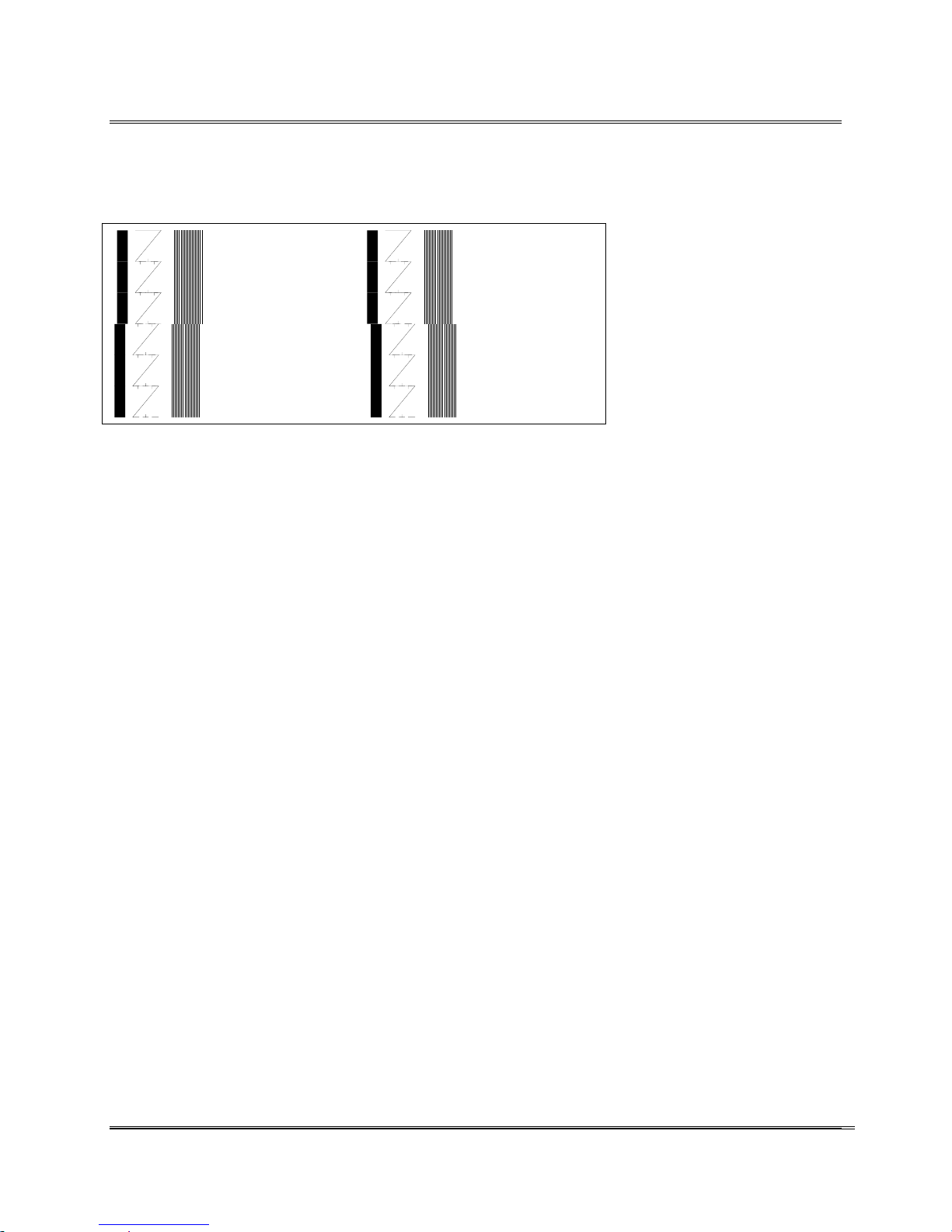
The two 3 Print Head Assemblies need to be synchronized
using the Adjust Print menu when the Test Pattern looks like
one of the two examples below.
Head 1 Bank A Head 1 Ba nk A
Head 2 Bank A Head 2 Ba nk A
Head 3 Bank A Head 3 Ba nk A
Head 4 Ba nk B
Head 5 Ba nk B
Head 6 Ba nk B
Head 4 Ba nk B
Head 5 Ba nk B
Head 6 Ba nk B
The Adjust Print menu has to be used when synchronizing the
two banks together. For more information about the Adjust
Print menu see the section in the Service Menu.
• Press the [+] plus or
[ - ] minus buttons to scroll
through the Service Menu options until the 1. ADJUST
PRINT option is displayed on the LCD panel.
Synchronizing
3 Print Head
Assemblies
• Press the [Enter] button to select this option.
• Press the [+] plus or
[ - ] minus buttons to scroll
through the Adjust Print menu options until the BANK
A TO BANK B option is displayed on the LCD panel.
• Press the [Enter] button to select this option.
• Now print out a Test Pattern by pressing the [Test
Env] button. The printer will print a Test Pattern like
the preceding example.
The Test Pattern consists of three rows of different patterns,
the first wide line and the eighteen vertical lines are used for
synchronizing Bank A and Bank B.
When the two patterns do not match to form long vertical
lines, then perform the following steps.
• Press the [+] plus
(MORE) button to increment the
Move Bank B value on the LCD display.
Revision C 30K USERS MANUAL Section 4 -
P/N 90-00203-001
10
Page 29
Printer Tips
A
A
A
• Press the [ - ] minus (LESS) button to decrease the
Move Bank B value on the LCD display.
• Press the [Enter] button to select the desired value. An
Asterisk (*) will appear in front of the new selection.
• Now print out a Test Pattern by pressing the [Test
Env] button. The printer will print another test pattern.
This time the test pattern is printed using the entered
selection.
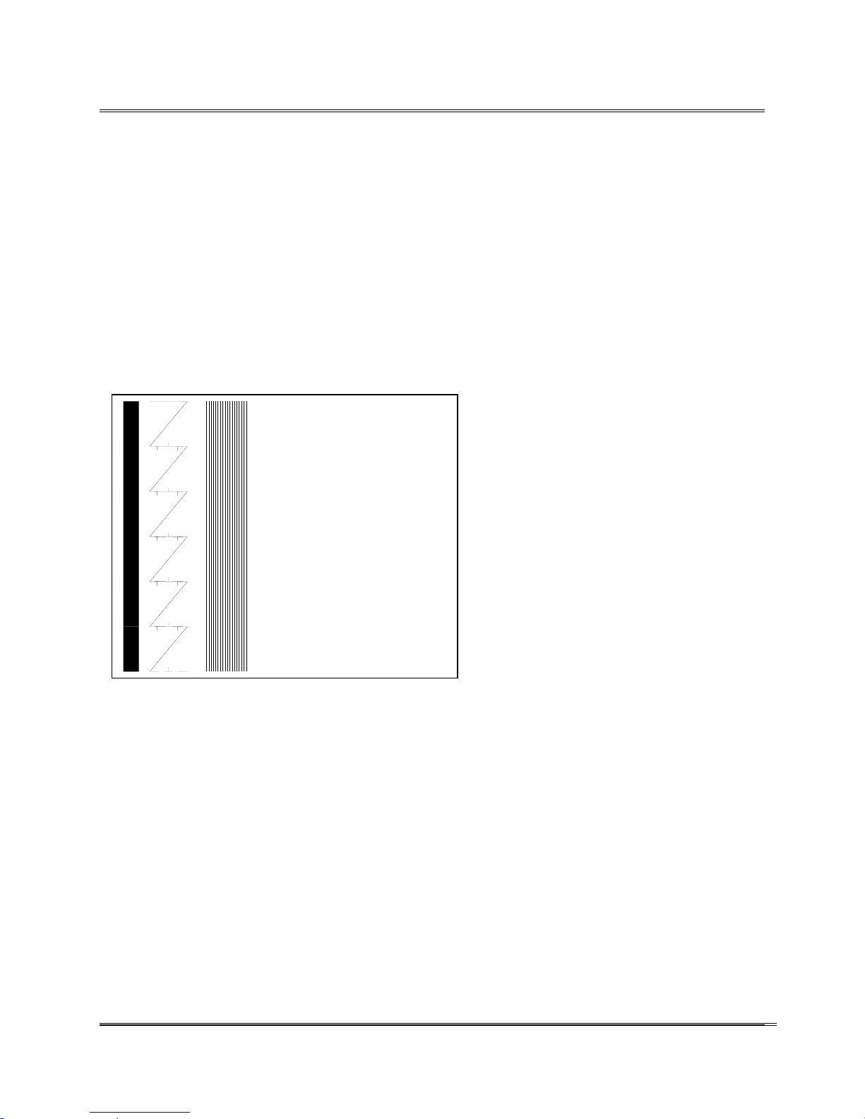
The pattern printed should look like the following example:
Head 1 Bank
Head 2 Bank
Head 3 Bank
Head 4 Bank B
Head 5 Bank B
Head 6 Bank B
When correct all lines should be straight.
• Press the [Menu] button several times to back out of
the Service Menu.
• Press the [On Line] button; now the printer is ready
for use.
Revision C 30K USERS MANUAL Section 4 -
P/N 90-00203-001
11
Page 30
Printer Tips
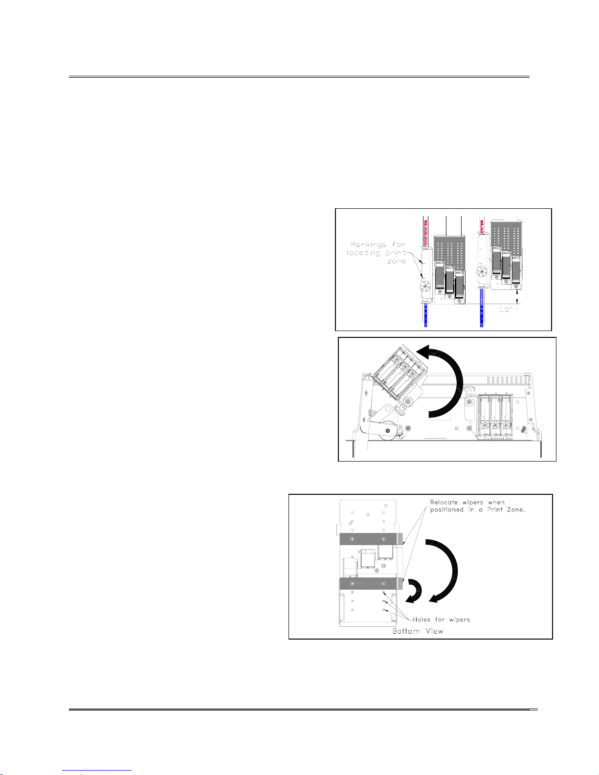
The 3 Print Head Assemblies have several holes for relocating
the two narrow Wipers. Move the wipers when synchronizing
banks of print cartridges or when two or more banks of print
cartridges are printing near the same area or the Print Head
Assembly has to print on or near the edge of a piece of media.
Move the wiper(s) when it causes a problem while the media
is on the Transport Belts.
Pay special attention when using Bank A with Bank B
of Print Head Assemblies. If the wipers run over an
area on the media where ink was just sprayed the
print will smear or smudge. The area where ink is
sprayed onto the media is referred to as a Print Zone.
Use the markings located on the bracket of each Print
Head Assembly to judge where the Print Zone for
Bank B is located. Move the Wipers to an area
outside of the Print Zone to maintain the best print
quality.
Perform the following steps to move the Wipers:
1. Remove the Cover from the printer.
Moving the
Wipers
2. Loosen the knob on top of the bracket that
secures the Bank of Print Head Assemblies.
3. Flip the Bank of Print Head Assemblies upside
down to expose the bottom of the assembly.
4. Remove the two screws securing the Wiper(s) on the
Print Head Assembly (Bank A or
B).
5. Relocate one or both wipers away
from the Print Zone or edge of the
media. Reinstall the wiper(s) using
the two screws on each wiper.
Note: Move the Wiper(s) far off to the side
if one or both are running along the edge of
the piece or just off the edge. This may
cause skewing of the print or paper jams.
Revision C 30K USERS MANUAL Section 4 -
P/N 90-00203-001
12
Page 31
Printer Tips
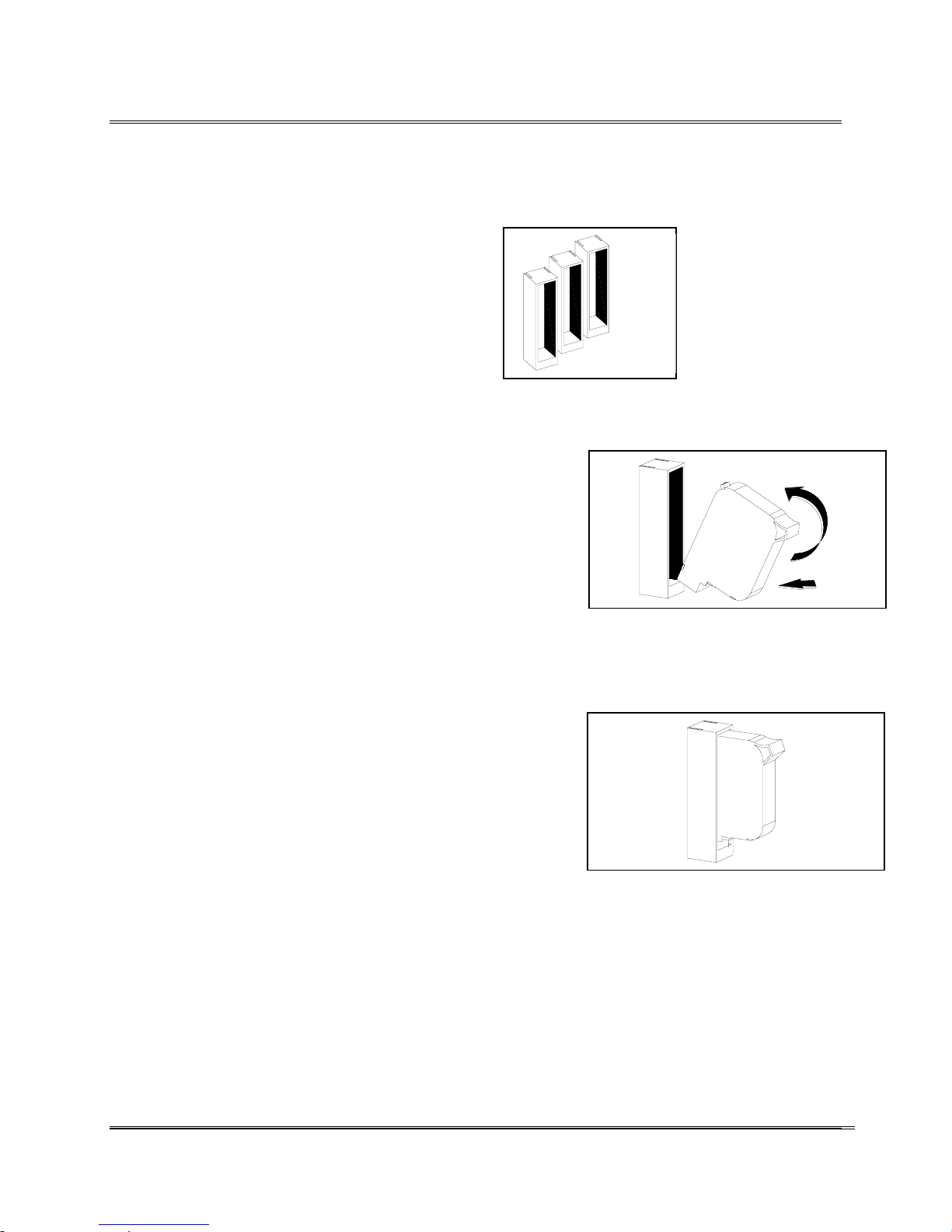
Included in the Accessories are Cartridge Capping Assemblies
to enclose the nozzles of the print cartridges. Proper use of the
Cartridge Capping Assemblies help in
maintaining the quality of print from the print
cartridges and help to prevent the ink from drying
and creating severe clogging of the print cartridge
nozzles.
Use the Cartridge Capping Assemblies when the
30K Printer is left to idle or shut down for a more
than a few minutes. To use the Cartridge Capping Assemblies
the ink cartridges have to be removed from the Print Head
Assemblies. Note: Keep the ink cartridges in order or
numbered otherwise the counter for the percent ink remaining
will give false information.
Employ the following steps to use the Cartridge Capping
Assemblies.
1. Remove the ink cartridge from the Print Head
Assembly. (See section 3-3 for information on
removing the ink cartridges.)
Prolonging
the life of
Print
Cartridges
2. Remove any excess ink on the nozzles.
3. Install the ink cartridge nozzle first into the Cartridge
Capping Assembly. Note: Clean any ink buildup on
the rubber seal to prevent it from obstructing the
nozzles.
4. Press the top section completely into the Cartridge
Capping Assembly.
5. Remove the ink cartridge from the Cartridge Capping
Assembly in reverse order. Suggestion: Check the
Print Head Alignment and perform a Purge of the ink
cartridges before operating the printer.
Revision C 30K USERS MANUAL Section 4 -
P/N 90-00203-001
13
Page 32

Printer Tips
Factors that Affect the Printers Performance
The 30K Printer is designed to give the best possible
performance, but the speed can be affected by these factors.
1. The amount of memory available in the computer.
2. Whether the printer is running as a network printer
or with a print spooler.
3. Pre-glued flaps on the media
4. Glossy or heavily waxed media.
5. Setting up margins, or sending non printable
characters or blank spaces in the records.
6. Sending blank lines in each record.
Tips for Running the Job
1. Use a computer dedicated to the printer only.
2. Tab magazines or stapled sheets.
Affects the
performance
of the
Printer
3. Eliminate blank spaces and lines in the records.
Extra characters take extra time to process.
4. Records with differing numbers of lines should be
followed with a page break or form feed.
5. When only one bank of print heads are required to
print the job use Bank B for printing.
Revision C 30K USERS MANUAL Section 4 -
P/N 90-00203-001
14
Page 33
Running with the Feeder Assembly
To use a feeder with the printer the setup requires two
considerations:
Use the following recommendations to help in setting up the
printer.
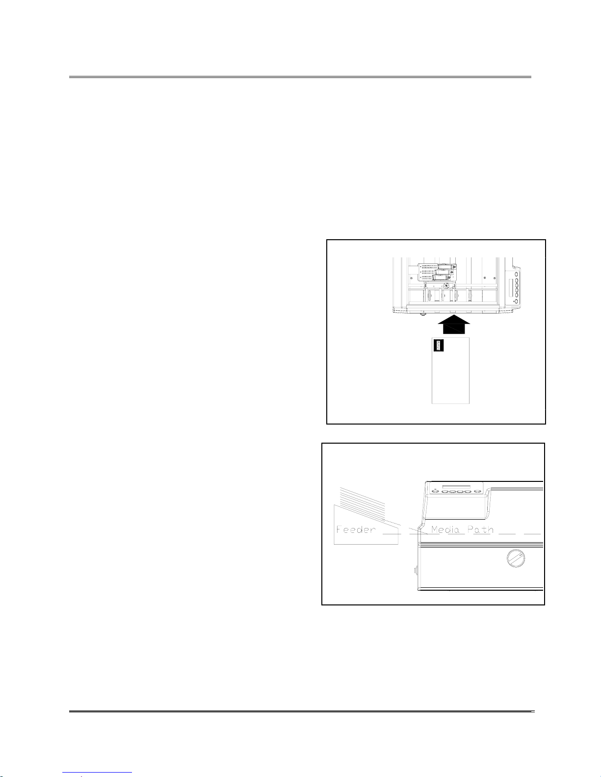
Media must go through the center of the Printer
To use a feeder with the printer it is best to position the feeder
so the media travels through the center of the printer. This is
very important with small or thin media like post cards or
envelopes. Make certain the media will travel
beneath the sensor or in the path of the sensor
Align center of media here.
beam.
The media has to travel through the path of the
sensor beam for the record to be printed. This is
very important with small or thin media like post
cards or envelopes. Use the illustration to the right
for an example.
Mount the feeder to the center of the printer. The
media must interrupt the sensor beam for the printer
to know when media is being fed.
The Entry Roller Assemblies must
take hold of the Media.
Move the feeder close enough for the printer to
have the Entry Roller Assemblies grab the media
The Entry Roller Assemblies guide the
media down the Media Path.
and guide it beneath the Print Cartridges.
The media can be sent at a slight incline or straight
into the printer.
Note: The Entry Roller Assemblies must have
control of the speed and direction of the media
otherwise poor print quality or feed errors may
occur.
Setting up a
feeder to
work with
the printer.
Revision C 30K USERS MANUAL Section 5 -
P/N 90-00203-001
1
Page 34
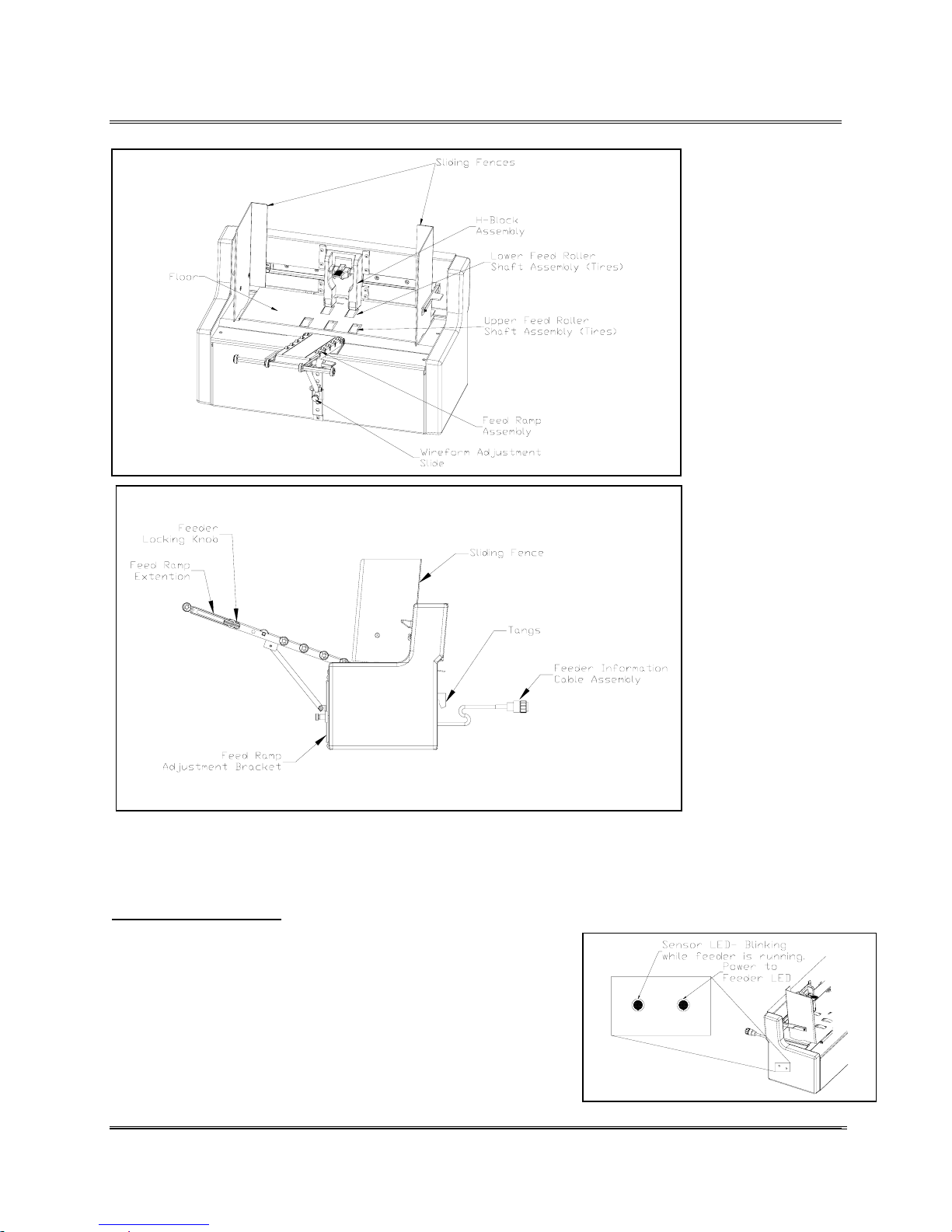
Running with the Feeder Assembly
Bryce Feeder
Parts &
Locations
The red lights on the back of the feeder indicate when the
feeder is operating correctly and when they are not lit
attention to the feeder is required.
When the LED’s are:
Feeder LED Steadily Lit- While the Feeder has power the
LED will remain lit.
Sensor LED Blinking – When media is being fed the LED
will blink as each piece passes beneath the sensor. When
media is blocking the sensor beam the LED will remain off.
Once the media is removed from the path of the beam the
LED is lit.
Revision C 30K USERS MANUAL Section 5 -
P/N 90-00203-001
What the
LED’s Do
2
Page 35
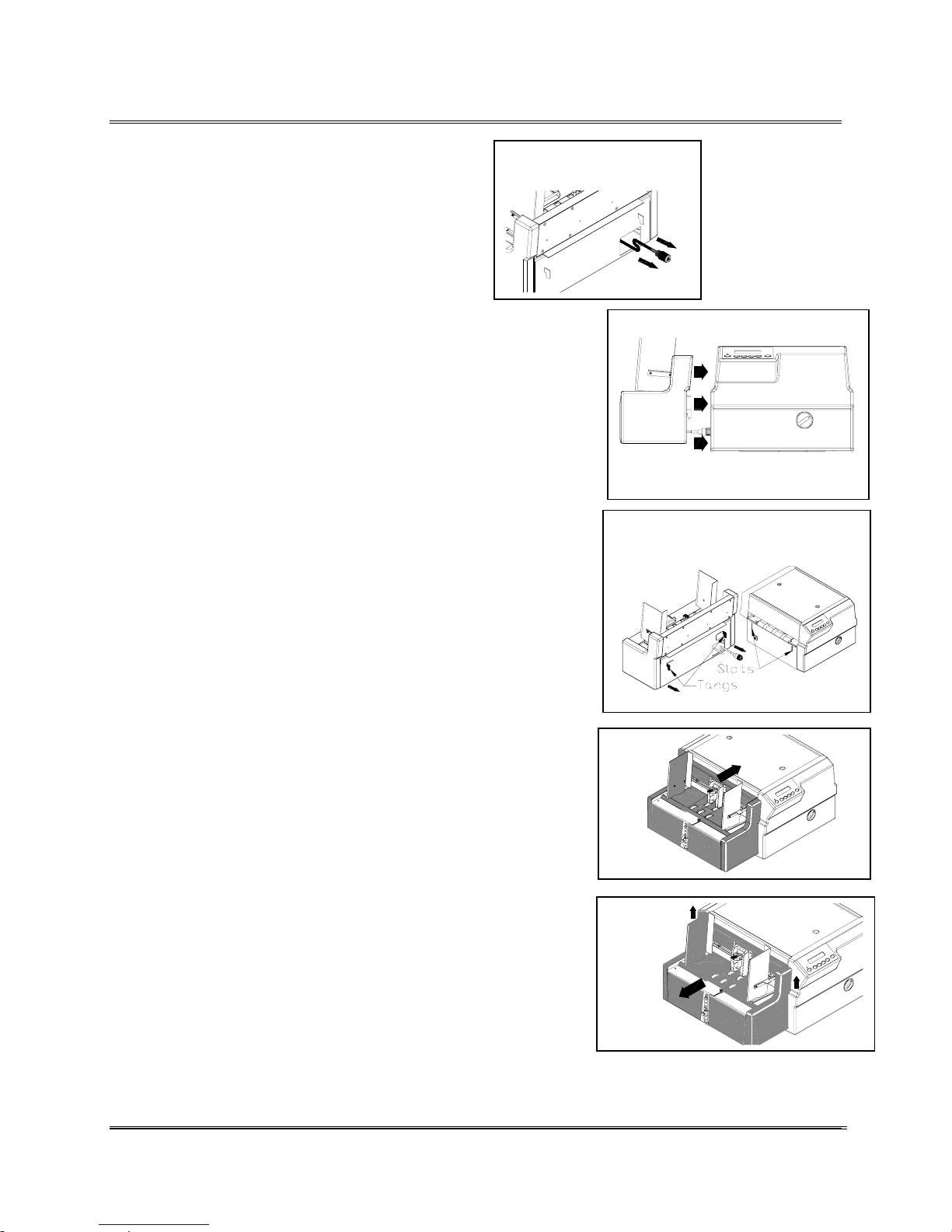
Running with the Feeder Assembly
1. Pull the connector out from the Feeder.
2. Move the Bryce Feeder next to the left
side of the Printer.
3. Plug the connector to the printer and twist to secure
connection.
4. Raise the Feeder up. Stuff extra cable back into the
Feeder Assembly.
Pull connector from
slot.
Move Feeder next to Printer.
Insert tangs into the slots on
printer.
Attaching
the Bryce
Feeder
Assembly
5. Hook the two tangs into the two slots on both sides of
the printer.
6. To remove the Bryce Feeder, lift the feeder up to
unhook from the Printer and pull the feeder away from
the printer.
7. Disconnect the Feeder from the Printer.
Revision C 30K USERS MANUAL Section 5 -
P/N 90-00203-001
3
Page 36
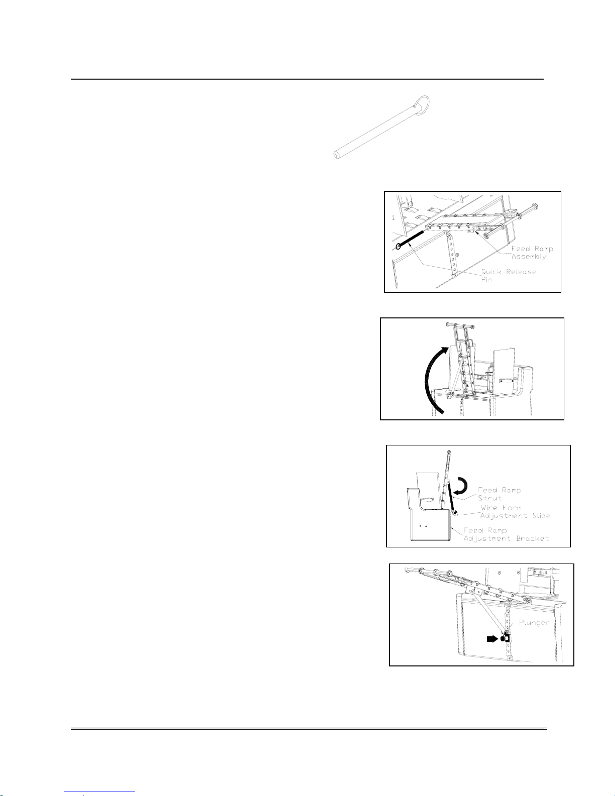
Running with the Feeder Assembly
1. Place the Feed Ramp Assembly onto the
Feed Ramp Holder. Align the holes on the
sides of the Feed Ramp Assembly to the
holes of the Feed Ramp Holder. (See figure
2.)
Figure 1
2. Insert Quick Release Pin (See figure 1.) completely
through the all the holes and out the other side of the
Feed Ramp Holder. Press it in until the Ring is flush
against the side of the Holder.
3. Raise the free end of the Feed Ramp Assembly up to a
nearly vertical position. (See figure 3.)
4. On the bottom of the Feed Ramp Strut is the Wire
Form Adjustable Slide. Place the Slide with the
plunger onto the top of the Feed Ramp Adjustment
Bracket located on the side of the feeder. (See figure
4.)
Attaching
the Feed
Ramp
Assembly
Figure 2
Figure 3
5. Pull the plunger out and lower the slide onto the
bracket. Release the plunger into one of the holes to
secure the Wire Frame Assembly in place. (See figure
5.)
Figure 4
Figure 5
Revision C 30K USERS MANUAL Section 5 -
P/N 90-00203-001
4
Page 37
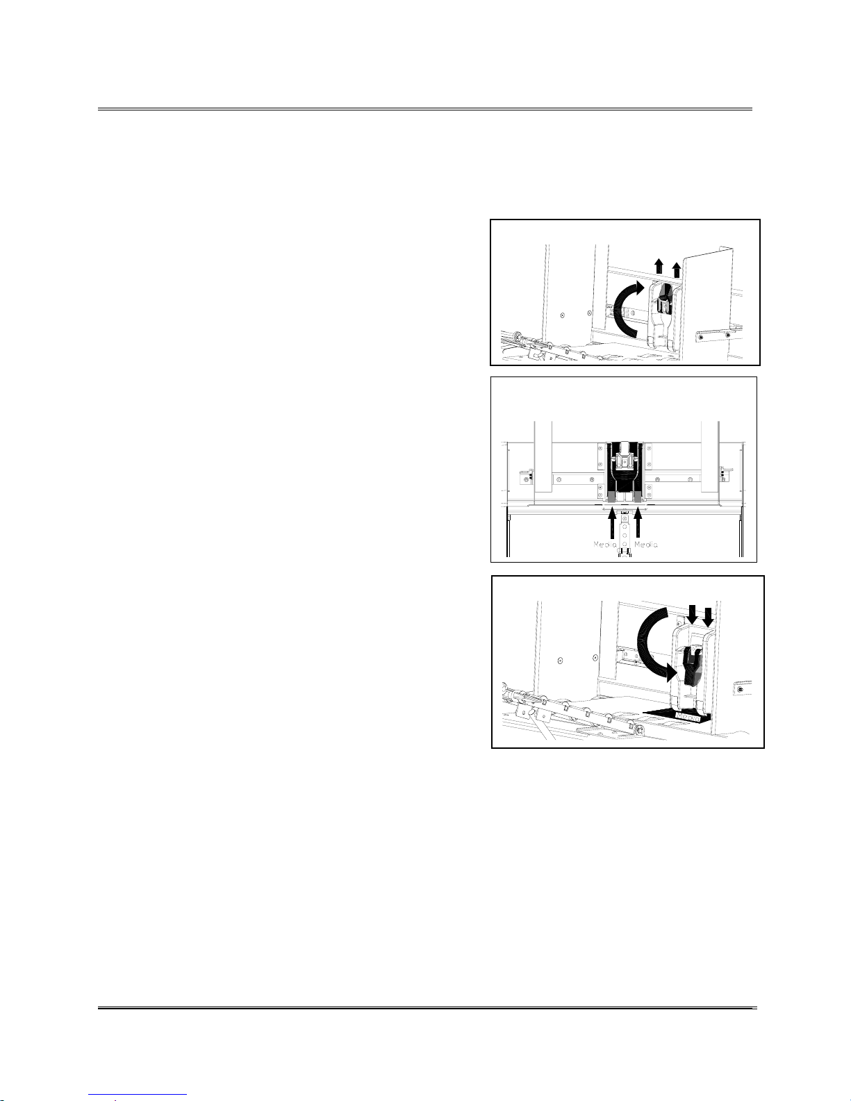
Running with the Feeder Assembly
Whenever the printer will be printing on a different media
type it is necessary to re-align the spacing between the HBlock and the rollers.
The next five steps will instruct the operator on how to
correctly adjust the H-Block spacing for printing on a
particular type of media. Readjust the thickness of the
H-Block if the printer continues experiencing misfeeds
or hesitation in feeding.
Open the Inner & Outer Fences away from the center of
the feeder.
1. Raise the Lever on the "H" Block Assembly
completely up to lift the block to the highest
position and secure in place.
2. Manually place one piece of the media between
the separator fingers (lower section of the "H"
block) and the feed roller.
4. Release and lower the "H" Block. Let it fall
freely onto the media. When lowering the "H"
block, verify the media is between all separator
fingers and the Feed Roller.
5. Press the Lever down to secure it in place.
6. The input bin area can now be filled with the
desired media for printing. The media stack
should be "shingled" when loaded into the input
bin with flap facing downward. Start with just a
few envelopes to start the stack and get the
proper contour then add more pieces.
• Post cards - set a smaller gap between the
separators and feed roller, by using standard copy
paper (.003" [0.076 mm] thickness).
Setting the
H-Block
Assembly
Lift lever up.
Place Media under H-Block
(Shown without the Feed Ramp)
Press lever down.
• Stuffed Media - set a larger gap between the
separator blocks and the feed roller, by adding two or
three, number ten (# 10) envelopes, on top of the
media before setting the separators
Revision C 30K USERS MANUAL Section 5 -
P/N 90-00203-001
Hint: If you are experiencing
feeding problems using post cards
or stuffed media. Try out the
suggestions listed for Post cards,
Stuffed Media and Magazines &
Booklets.
5
Page 38
Running with the Feeder Assembly
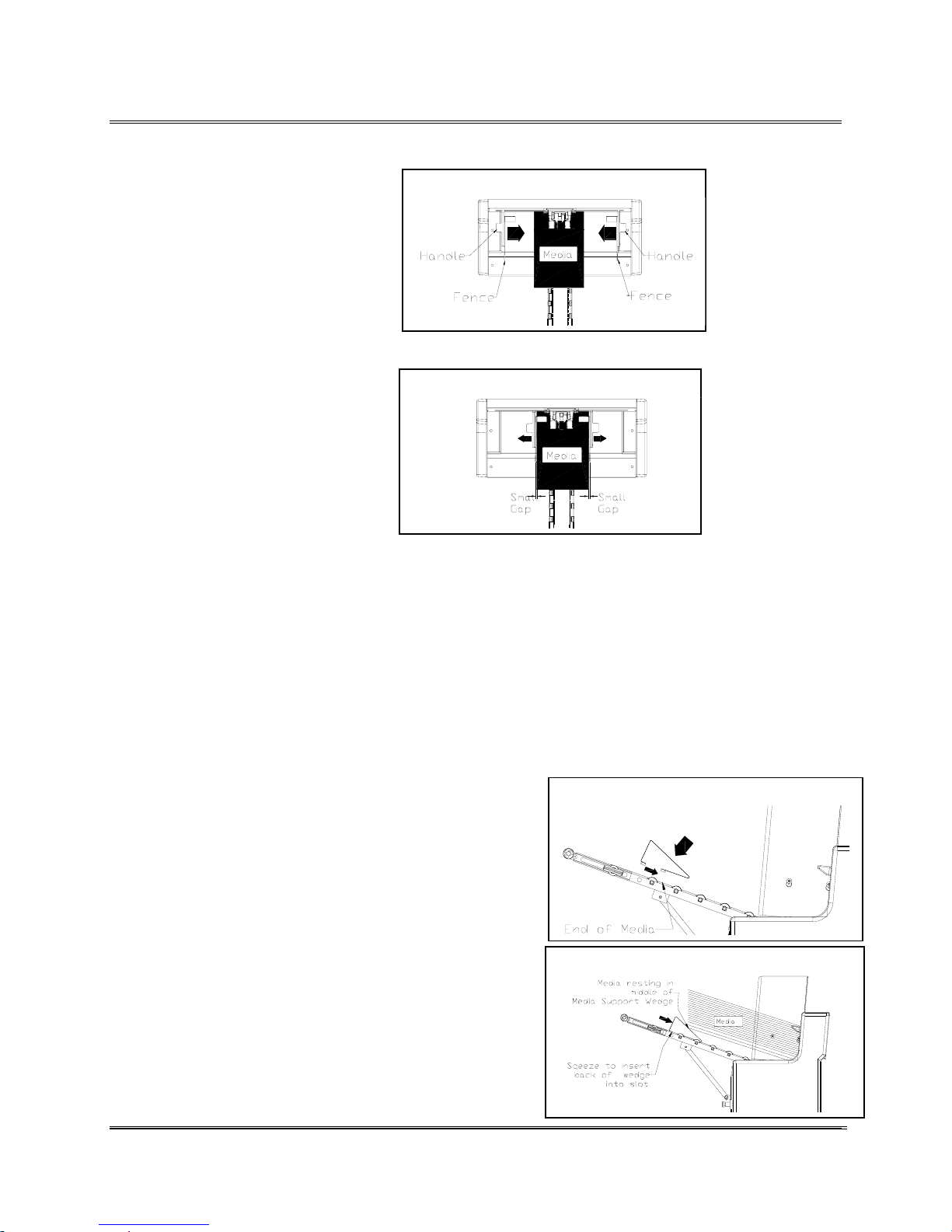
1. Set one or a few pieces of
media in the center of the
Feeder.
2. Grab the handles on the
sides of both fences and
push the Fences towards the
media. Both Fences will
move simultaneously
towards the media to trap it between the Inner & Outer
Fence. Push the fence up
against the side of the
media.
3. Move one of the fences back
to leave a gap the width of a
envelope between the media
and the fences. The fences
have to be close enough to
keep the media from going in at an angle but loose
enough to allow the media to freely drop down onto
the Feed Rollers.
Slide Fences towards media
Leave small gap
Setting the
Sliding
Fence
1. Lift the media up from the Feed Ramp Assembly. Take
notice where the end of the media rests on the Feed
Ramp Assembly.
2. Locate where the end of the media was and
insert the front end of the Media Support Wedge
and then push forward to hook in the slot. This
will place the Media Support Wedge so the
media is halfway up the angled front edge.
3. Slightly squeeze the back of the wedge to insert
it into a slot.
4. Release the wedge and the tension will lock the
wedge in place. Now lower the media down.
Check that the bottom piece of media is almost
halfway up the Media Support Wedge.
Setting the
Media
Support
Wedge
Insert front of wedge.
Media located in middle of wedge.
Revision C 30K USERS MANUAL Section 5 -
P/N 90-00203-001
6
Page 39
Running with the Feeder Assembly
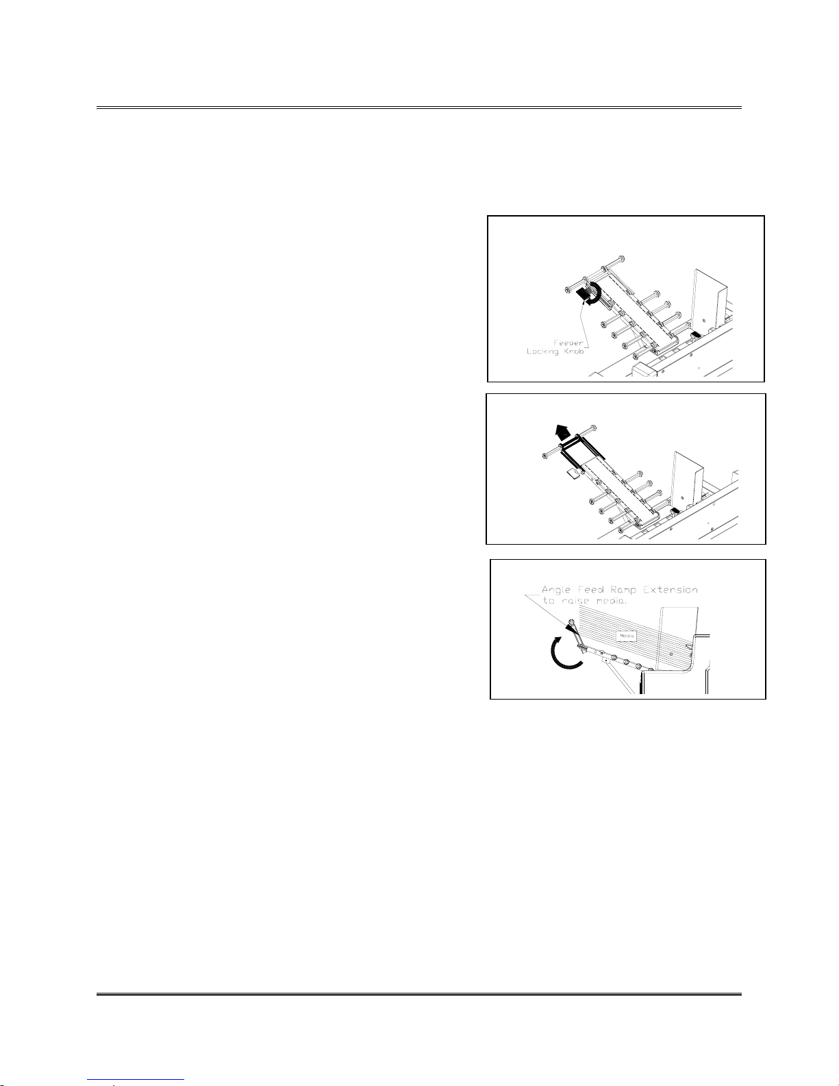
Overly long media is accommodated using the Feed Ramp
Extension, also it will perform the same functions as the
Media Support Wedge does with much shorter media.
1. Place a piece of the media on the Feed Ramp
Assembly.
2. Turn to loosen the Feeder Locking Knob.
3. Pull the Feed Ramp Extension out from the Feed
Ramp Assembly.
4. Angle the Feed Ramp Extension up to create a
small gap between the media and the Feed Ramp
Assembly.
5. Turn the Feeder Locking Knob to secure the
Feed Ramp Extension. Note: The gap and angle
of the Feed Ramp Extension will vary with the
type of media used. Adjust the angle of the Feed
Ramp Extension or Feed Ramp itself if the
Feeder Assembly is having difficulty consistently
supplying the printer with media.
Setting up and using the
Feed Ramp Extension
Loosen the Locking Feeder Knob.
Pull the Feed Ramp Extension out.
Angle the Feed Ramp Extension up.
Revision C 30K USERS MANUAL Section 5 -7
P/N 90-00203-001
Page 40
Printer Menu System
Front Panel Controls and LCD Display
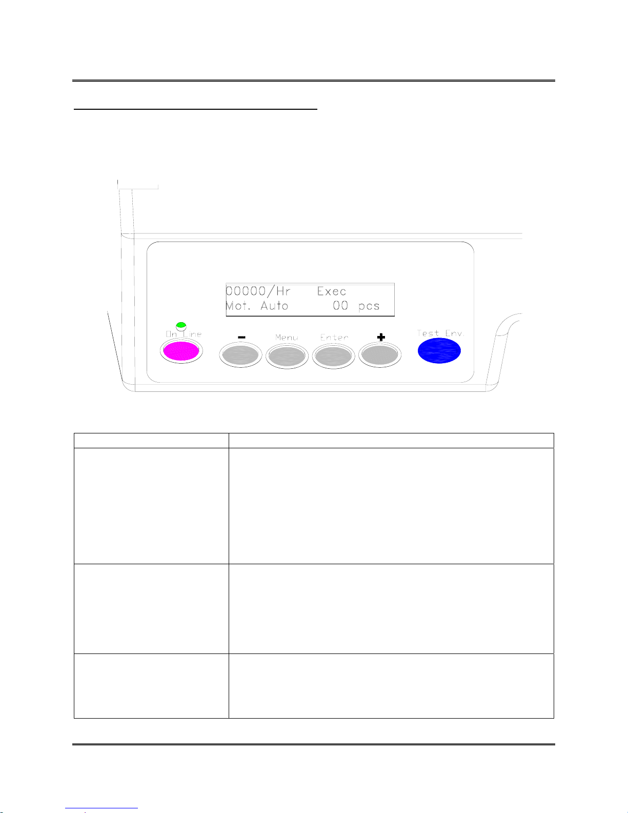
Use the controls on the Front Panel Assembly, consisting of six control buttons and an LCD display, to
set up the Addressing Printer for proper operation with the computer system.
Note: Press the [+] & [-] buttons
simultaneously to change the
motor settings on the printer.
The control button definitions are:
Button
[ON LINE]
[TEST]
[MENU]
Function
Toggles the printer either On Line or Off Line.
Begins printing accepted address data (records) from the computer or
data in the buffer.
Exits the menus with out changing menu settings.
Allows the printer to resume printing after an error occurs.
Prints a internal test message.
Hold down for continuous printing of the test message.
Prints menu settings and internal alignment patterns for the printer
when in the appropriate menu.
Press the [Menu] button to access the Main Menu.
Press and hold the [Menu] button for two (2) seconds to access the
Setup Menu.
Revision C 30K USERS MANUAL Section 6 - 1
P/N 90-00203-001
Page 41
Printer Menu System
Depress the [Menu] and [-] buttons to access the Service Menu.
Exit the control panel menus. First press [Enter] to save a menu
setting.
[ENTER]
[+] / [-]
Selects a menu option displayed on the control panel.
Saves a new menu setting. An asterisk (*) will appear to the right of
the value to indicate the new value has been entered.
Scroll up [+] and down [-] through the menu options.
Enters a YES [+] or NO [-] for a particular menu option.
Use both keys together to start the printers transport motor to run
continuously or to set the printer so it will only run when data is sent
to the printer.
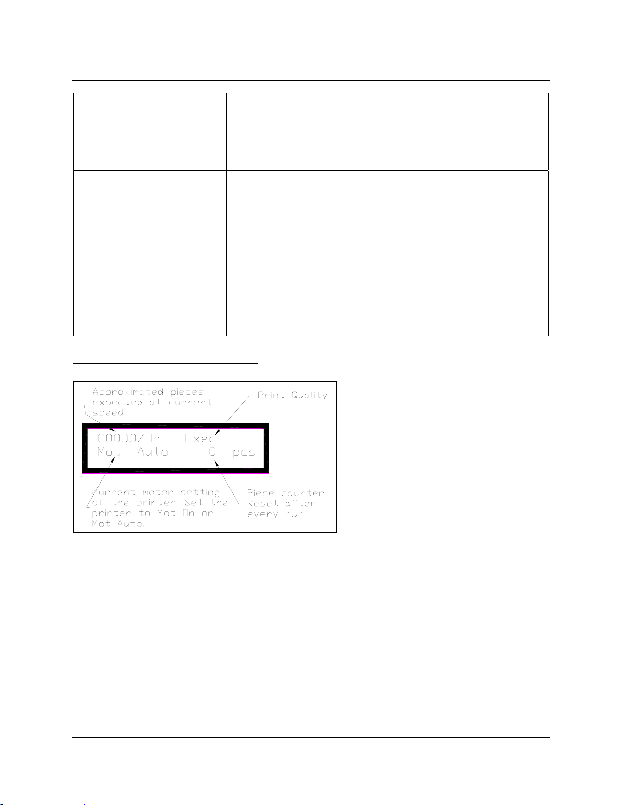
What does the display show?
Conventions used in the Printer Menu System section.
Bold with brackets is used for the [Menu], [On Line], [Enter], [+] Plus, [-] Minus buttons
when they must be pressed to program or operate the printer.
Special fonts are used to highlight words that appear on the LCD display, and menu options: i.e.
MAIN MENU, SETUP MENU. Italics are used to define the function of the printer menu
option.
Revision C 30K USERS MANUAL Section 6 - 2
P/N 90-00203-001
Page 42
Printer Menu System
Main Menu
Use this menu to choose the format and style of address printed and for information to assist in
production. Selected menu options from a sub-menu will appear first in the list of options.
Note: The printer driver overrides most control panel settings in the printer. Some of the control
panel settings are also configured in the printer driver.
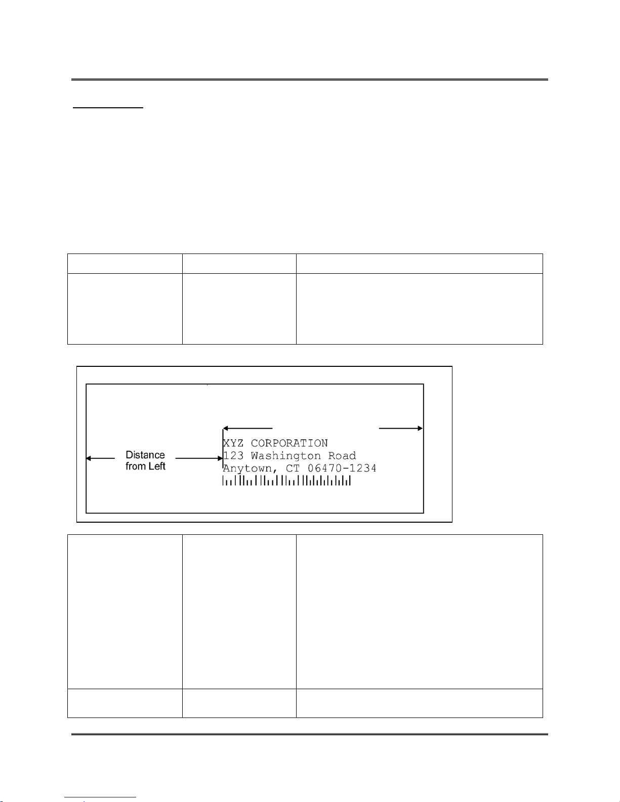
1. ADDRESS LAYOUT
Use this option to change the page layout for your mail piece.
Menu Items Selections Explanation
A. Distance
From Left
Example:
A. Distance to
Right
0.00 to 13.50 This menu option allows you to change the position
of the record horizontally on the media. Records
will appear upside down when viewed from the
front of the printer. Note: This menu item only
appears when the Orientation is set to Normal.
Distance to Right
0.00 to 13.50 This menu item only appears when the Orientation
is set to Invert. This menu option allows you to
change the horizontal position of the record on the
media. Distance to Right is the distance measured
from the Right edge of the media to the first
printable character of a line (reading from left to
right). Records will appear right side up when
viewed from the front of the printer. Note: Setting
this value too low will force long records to be
clipped or create an error.
B. Distance
From Top
Revision C 30K USERS MANUAL Section 6 - 3
P/N 90-00203-001
0.00 to 3.00 This menu item allows you to change the position of
the record without moving the Banks of Print
Page 43
Printer Menu System
Cartridges. The printer achieves this by reducing the
available area used for printing. Note: Increasing the
setting decreases the print area. The recommended
setting for Distance From Top is 0.00.
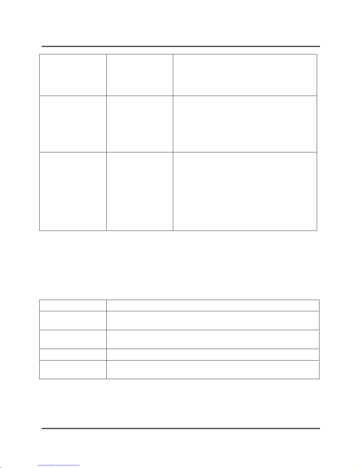
C. Line Spacing
D. Orientation Normal or
Automatic
3 lines / inch
4 lines / inch
6 lines / inch
8 lines / inch
Invert
This sets the distance between lines of text. It is
measured as the number of lines per inch of text.
Note: Whenever changing the point size of the font,
use the automatic line spacing option. The printer
will automatically select the correct setting for the
increased or decreased font size of the characters
being printed.
This item changes the direction that the print
appears on the media.
Normal prints upside down when viewed from the
front of the printer.
Invert reverses the print 180 degrees. The print
is right side up when viewed from the front of
the printer. Setting the printer to Invert changes
the menu choice from
Distance From Left
to Distance To Right.
2. PRINT QUALITY
This option changes the number of dots sprayed to print characters or graphics on the media.
Changing the amount of ink sprayed also affects how fast the Transport Belts are capable of
running. The LCD display will show the new item whenever the Print Quality is changed. These
menu items are available in the printer driver and override the control panel settings.
Menu Items Explanation
Executive
Letter
Draft
Super Draft
This is the darkest of the four print qualities, the slowest print speed and uses
the most ink.
Letter quality is used for documents that require a finished, polished
appearance.
Draft quality will print documents fast and save ink.
This option offers the highest print speed and prints the lightest of the four
print qualities.
Revision C 30K USERS MANUAL Section 6 - 4
P/N 90-00203-001
Page 44
Printer Menu System
3. FONT
Use this option to alter the fonts characteristics: typeface, point size, spacing, stroke weight, and
style. The printer driver downloads Windows True Type fonts and overrides internal fonts
selected through the control panel.
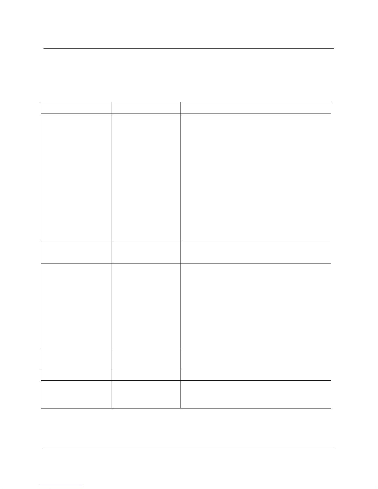
Menu Items Selections Explanation
A. Name Courier
San Serif
Roman
Baxter
Dingbat
Hancock
Marina
Quincy
Silicon
Springer
Stencil
Windmill
B. Size
C. Width Condensed (50%)
4 to 30 This item changes the size of the internal font.
Thin (75%)
Normal (100%)
Wide (125%)
Expanded (150%)
Select the style of the internal font to print the
records with.
This item to changes the width of spaces between
characters and the width of characters.
Normal (100%) print width is the standard width of
characters and spaces between characters.
Thin (75%) and Condensed (50%) will decrease the
spacing between characters and decrease the width
of characters.
D. Bold
E. Italic
F. Outline
On or Off This item increases the character stroke weight
On or Off This item refers to the oblique shape of a character.
On or Off This item prints only the outline or the edge of the
Revision C 30K USERS MANUAL Section 6 - 5
P/N 90-00203-001
Wide (125%) and Expanded (150%) increase the
width of characters and spaces.
(thickness of print).
fonts shape. All the records printed using Outline
will appear as hollow text.
Page 45
Printer Menu System
4. BARCODE
Use this option to print a USPS (US Postal Service Postnet Barcode) barcode on the piece of
media and to place it above or below the record. Note: A CASS certified mailing program is
recommended when generating a USPS barcode. The requirements to print a USPS barcode are
shown in Appendix H.
Menu Items Selections Explanation
A. Location Above Address
Below Address
Off
B. 5 Digit
On/Off
C. Bar Width
On or Off This item prints a 5 Digit barcode for a five digit zip
6 to 12 This item will increase the width or decrease the
Select the US Postal Service Postnet Barcode
options from the following selections:
ABOVE ADDRESS: Prints the barcode in the
address block above the first line of the address on
the media.
BELOW ADDRESS: Prints the barcode below the
last line of the address in the address block on the
media.
OFF : Stops the printing of a Delivery Point
Barcode (DPBC) on the media.
Note: This option has the printer generate the USPS
barcode.
code. Note: Only a 5 Digit barcode is printed for a
five digit zip code when enabled. A Delivery Point
Bar Code cannot be generated from a five digit zip
code.
width of the bars generated for the USPS Postnet
and Planet barcodes. Select this item to counteract
the variance in the barcodes due to material, print
quality, inks, etc.
5. ADDRESS RECOVERY
When something goes wrong while printing use this option to direct the printer to re-print up to
99 of the last records or to clear the printers memory of all records.
Menu Items Selections Explanation
A. Get
Addresses
Revision C 30K USERS MANUAL Section 6 - 6
P/N 90-00203-001
NONE TO RECOVER
or
00 to 99
Press the [Enter]
button to select the
This option retrieves up to 99 records from the data
buffer.
The display will say 00: and show the first 16
characters of the last address printed. If NONE TO
RECOVER is first displayed then the data buffer is
Page 46
Printer Menu System
B. Clear Memory
record and advance the
display to the next to
last record.
Yes or No This option removes any data left in the data buffer.
empty.
The alternative way to clear data from the Data
Buffer is to press the [+] plus and [–] minus buttons
simultaneously.
6. CLEAR COUNTER
Use this option to clear the piece (batch) counter back to zero.
Menu Items Selections Explanation
Yes or No This option resets the counter to zero on the display.
Select No to leave the current number of pieces
printed (pcs) on the LCD display.
7. JOB SETTINGS
The printer has the ability to save or load up to eight different menu presets into memory. This is
extremely useful for a quick setup of the printer for redundant tasks.
Menu Items Selections Explanation
A. Load
B. Save
Press the [Test] button
to printout the current
menu settings.
1 to 8
1 to 8
This option changes the printers menu settings such
as size and type of font, the lines per address, etc.
This option saves the current menu setup or
configuration as a job number (1 through 8). Make a
record of the menu configurations for each job
number by pressing the [Test] button to get a
printout after the job number is saved.
Revision C 30K USERS MANUAL Section 6 - 7
P/N 90-00203-001
Page 47
Printer Menu System
8. CONVEYER TIME
This item increases the length of time the conveyer will stay on. Generally, when the print
quality is set higher than draft, and / or, print width is larger than normal, the drying time of
printed records must be increased to prevent smearing or smudging of addresses. Special
consideration of ink drying time and media handling for glossy or tyvek media should also be
considered when using a conveyer.
Menu Items Selections Explanation
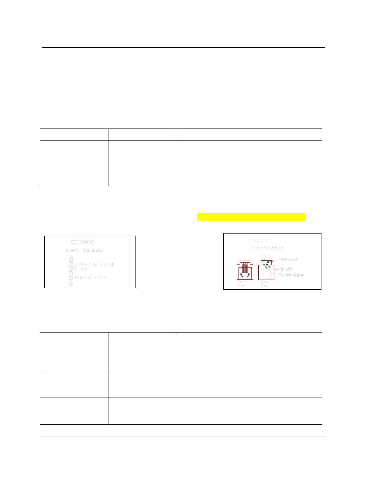
Use a 5 volt DC relay switch or a Bryce Pulse Box inline with the Accessory Port and the Conveyer
when connecting to the 5 VDC line [Pin 3] and the Conveyer Signal line [Pin 2]. Reference the Schematic
for the pins to use when connecting to the Conveyer Port. (See Section K for ordering information)
0.00 to 2.00
seconds
This item modifies the amount of time the conveyer
continues to run after printing a record. Changing
the time for the conveyer to remain running alters
how the media is shingled on the conveyer.
9. IMAGE OVERLAY
This menu item is used in conjunction with the Overlay Printer Driver. Use this option to print
redundant text or graphics in the same location on every piece. The Image Overlay option is best
used for printing a company logo and return address.
Menu Items Selections Explanation
A. First Image
Overlay
B. Clear
Overlay
C. Print
Overlay First
Revision C 30K USERS MANUAL Section 6 - 8
P/N 90-00203-001
Enable or Exit This option saves the very first record or graphic
Press [Enter] to
Clear or Exit
Enable or Disable This option prints the data sent for the overlay onto
received into the printers’ memory as an overlay.
This option clears the overlay data in the printers’
memory.
the first piece. Use this piece to verify the location
of the overlay is correct.
Page 48
Printer Menu System
10. PURGE PRINT HEAD
This menu item is to clean the ink jet cartridge nozzles. The purge process fires all the ink jet
nozzles onto a piece of media to dislodge and clear any dried ink on the print nozzles. Often this
will return the print quality to a normal level.
Menu Items Selections Explanation
Yes or No
This item will fire all the nozzles of a print head
onto a piece of media. Note: Once the purge is
started the [-] minus button may be pressed to stop
the cycle.
11. RESET INK COUNT
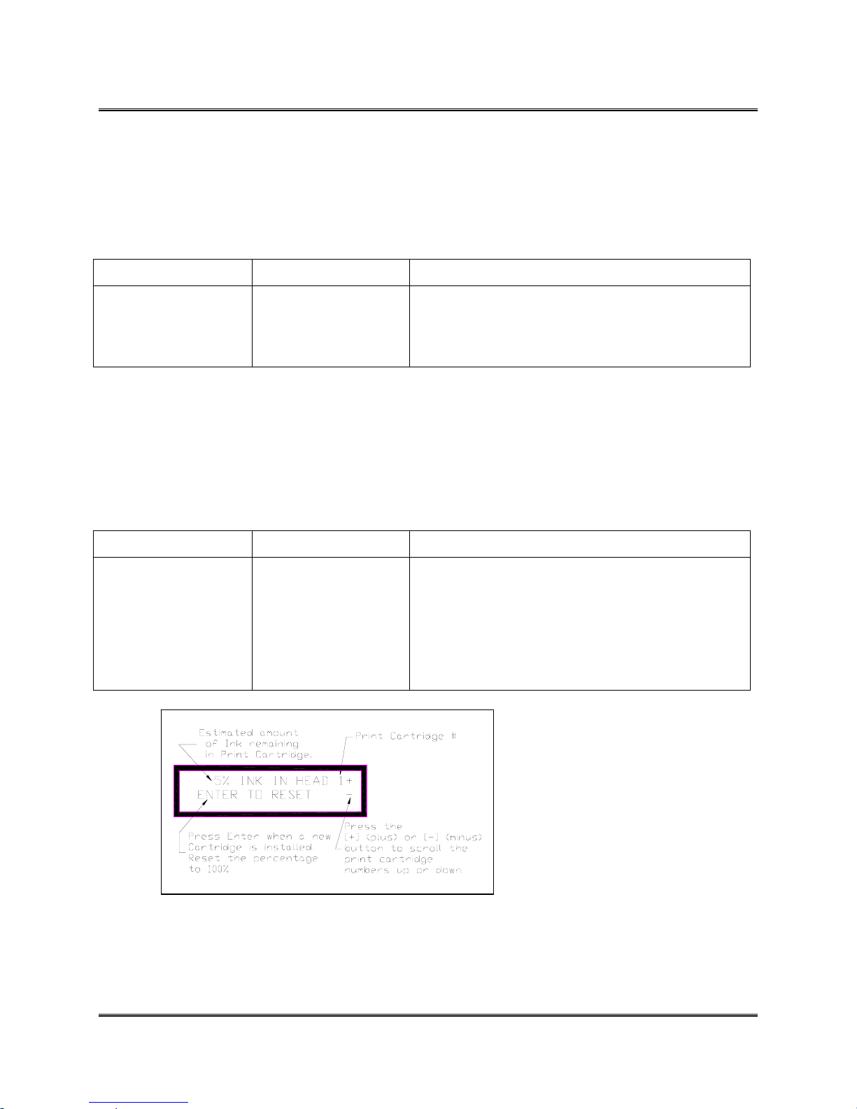
The printer calculates the amount of ink used by each of the Print Cartridges. When the red led
on a Print Head Assembly starts to blink it is a signal that one or more of the Print Cartridges is
less than 5% full and it must be changed relatively soon. After new Print Cartridges are installed
the Ink Count needs to be reset to stop the red led from blinking.
Menu Items Selections Explanation
1,2,3,4,5,6
This item displays the estimated amount of ink
remaining in the print cartridge(s).
Press the [
through the print cartridges 2,3,4,5 and 6. When the
desired Print Cartridge number is displayed, press
the [Enter] button to reset the percent ink to 100%.
+] plus or [-] minus button to scroll
Note: The calculation used to
determine the percentage of ink
available is based on the HP
51645A Print Cartridge or the HP
51645A Ink Reservoir System.
Revision C 30K USERS MANUAL Section 6 - 9
P/N 90-00203-001
Page 49
Printer Menu System
SETUP MENU
The Addressing Printer has a Setup Menu that lets you configure the Addressing Printer so it will
function correctly with the computer and computer software. Use the Setup Menu to also display
the menus in another language besides English. Hold down the [Menu] button for two (2)
seconds until SETUP MENU is displayed on the first line of the LCD. Select the desired menu
option when it appears on the second line of the LCD.
1. STOP ON FEED ERR (ERROR)
Use this option to stop the printer from feeding more media when an error occurs. Otherwise the
printer will continuously feed media until the record is accurately printed before continuing onto
the next record. Stopping the printer when an error occurs is helpful when the media is in short
supply.
Menu Items Selections Explanation
Off or On This item stops the printer from operating after a
“Early Feed Error” occurs.
2. FEEDER SIGNAL
The Feeder Signal option is for feeders that work with 5-volt DC signals. The printer will give a
signal to the feeder when it receives one or more records. When the Stop On Feed Error option is
turned ON and an error occurs the feeder signal will be cleared to stop the feeder. See Section
Connecting to the Conveyer /Feeder Port.
Menu Items Selections Explanation
A. None
B. On /Off
Control
C. Pulse Off
Control
Press the [Enter]
button to select this
item.
Press the [Enter]
button to select this
item.
Press the [Enter]
button to select this
item.
This item disables the Feeder Signal option.
This item turns a 5 volt signal on whenever one or
more records are in the buffer to be printed.
The signal is turned off (0 volts) once the last record
in the buffer is being printed. Note: The signal will
also be turned off (0 volts) when a “Early Feed
Error” occurs while the Stop On Feed Err (Error)
option is enabled.
This item turns on a 5 volt signal when the sensor
detects the piece to print the last record in the buffer
on.
Revision C 30K USERS MANUAL Section 6 - 10
P/N 90-00203-001
The signal is turned on (5 volts) once the sensor
detects the piece to print the last record in the buffer
on.
Page 50
Printer Menu System
C.
Menu Items Selections Explanation
(Continued)
The signal is then turned off (0 volts) a second later.
Note: The signal is turned on (5 volts) when a
“Early Feed Error” occurs while the Stop On Feed
Err (Error) option is enabled.
If the Pulse Off Signal option is selected, the
external feeder signal will be asserted when the
leading edge of the envelope for the last address to
be printed is detected at the print heads or when an
early feed error is detected (if the Stop On Feed Err
option has been selected). In either case, the signal
will be cleared 1 second later.
D. On / Quick
Off
E. Signal
Polarity
Press the [Enter]
button to select this
item.
Active ON or
Active OFF
Press the [Enter]
button to select this
item.
This item turns a 5 volt signal on whenever one or
more records are in the buffer to be printed.
The signal is turned off (0 volts) once the sensor
detects the piece to print the last record in the buffer
on. Note: The signal will also be turned off (0 volts)
when a “Early Feed Error” occurs while the Stop On
Feed Err (Error) option is enabled.
This item reverses the signal used to trigger the
feeder. The Signal Polarity only affects the ON/OFF
Control and ON/Quick OFF menu items.
Active ON activates an external feeder by
switching on the feeder signal.
Active OFF activates an external feeder by
switching the feeder signal off.
3. LINES PER ADDRESS
Set the number of lines of text the record will consist of when printing onto the media.
Menu Items Selections Explanation
1 to 66
4. LINE TERMINATION
This item allows the printer to interpret what the Line Termination (end of a line of text) is for
different operating systems or software. Choose from the various Line Termination formats to
get the correct line count and then the record will print correctly.
Revision C 30K USERS MANUAL Section 6 - 11
P/N 90-00203-001
Set the number of lines to match the number of lines
in a record that will be sent to the printer.
Page 51
Printer Menu System
(
Menu Items Selections Explanation
CR=CR;LF=LF
CR=CR+LF;LF=LF
CR=CR;LF=CR+LF
CR=CR+LF;LF=CR+
LF
The typical software line termination is CR = CR;
LF = LF. If your software is not typical then the
Line Termination can be modified.
5. HEX DUMP MODE
Utilize this option to print the raw ASCII data (HEX Code) that is being sent to the printer.
Menu Items Selections Explanation
Off or On
Prints the ASCII data being sent to the printer.
The media width must be a minimum of 7 1/2”
or 191 mm when running in HEX Mode. The
page orientation, margins and number of lines
are defined by the ADDRESS LAYOUT and
LINES/ADDRESS. The maximum number of
usable lines is 16.
Note: Clear the data buffer before sending data to
the printer.
6. LANGUAGE
Customize the printer to match the keyboard of your printer, convert measurements from inches
to millimeters and translate the menus from English. Most menus that use inches for
measurements are converted to millimeters.
Menu Items Selections Explanation
A. Symbol Set ISO 6 ANSI
ASCII
ISO 69 FRENCH
ISO 21 GERMAN
ISO 4 UK
ISO 60 NORW /
DAN
ISO 11 SWED /
A.
Continued)
ISO 15 ITALIAN
ISO 17 SPANISH
ISO 61 NORW /
FIN
Match the printers’ International Standards
Organization (ISO) symbol sets and substitution
tables to the one used by the software.
The printer has International Standard Organization
(ISO) language symbol sets to use when printing in
another language. A symbol set contains collections
of the symbols and characters that make up a
language. For a listing of the characters for the ISO
symbol sets see Appendix D.
Note: The character set CP1250 is only available
after the polish characters are installed on the
machine.
Revision C 30K USERS MANUAL Section 6 - 12
P/N 90-00203-001
Page 52
Printer Menu System
Menu Items Selections Explanation
DAN
ISO 10 SWED /
FIN
ISO 16
PORTUGUE
SE
ISO 8859
ROMAN 8
WINDOWS LATIN 1
PC 8
B. Inch /
Millimeter
C. Menu
Language
CP 1250
Inch or Millimeters
ENGLISH
GERMAN
FRENCH
ITALIAN
This option converts the printer measurement
system from inches to millimeters and vice versa.
This option will convert the Main Menu and Setup
Menu to their translations in the listed languages.
SPANISH
DUTCH
POLISH
JAPANESE
7. TRANSPORT SPEED
Use this option to change the transport speed of the printer.
Menu Items Selections Explanation
50% to 100%
Select this item to decelerate the transport belt to
increase drying time for the ink and assist in the
handling and sorting of the media by decreasing the
throughput. Varying the speed of the transport belt
will not affect the print quality.
8. POSTAL BUNDLE BRK (BREAK)
This option will stop the printer for a few seconds before proceeding to print the rest of the
records. This allows time for bundling the presorted records together and separate the bundle
from the next batch of records being sent to the printer. Use the menus to customize the
command to suspend operation and to set how long the printer must wait before it resumes
operating.
Menu Items Selections Explanation
Revision C 30K USERS MANUAL Section 6 - 13
P/N 90-00203-001
Page 53
Printer Menu System
A.
Enable/Disable
Break
Off or On
Select the type of command the printer must receive
before it stops the feeder to set a gap between
batches while it is operating.
The marker to set a break consists of the repetition
of a single character appearing on a single line to
start the printer to pause. The Example below
displays what the printer is looking for before
pausing the print job.
Example of using a
series of 3 ‘#’
characters in the
Horizontal Break
Marker setting to
pause the printer.
###
**************23
XYZ Corporation
123 Washington Road
Anytown, CT 06470-1234
Menu Items Selections Explanation
B. Break
Character
C. Break Char
Count
D. Pause Time
! ” # $ % & ’ (
) * + - . /
0 1 2 3 4 5 6 7
8 9
: ; < = > ? @
A B C D E F G H
I J K L M N O P
Q R S T U V W X
Y Z
Note: Send the [SOH
ASCII (01)] character
to trigger a Postal
Bundle Break.
01 to 10
0.00 to 31.75
This option sets what character the printer must
receive before it will momentarily halt working. The
list of characters to select from are:
! ” # $ % & ’ ( ) * + - . /
0 1 2 3 4 5 6 7 8 9
: ; < = > ? @
A B C D E F G H I J K L M N
O P Q R S T U V W X Y Z
These characters and symbols range from
[! ASCII (33)] to [Z ASCII (90)] in a ASCII Table.
Set the number of occurrences the character or
symbol must appear in succession before the printer
can send a Postal Bundle Break signal.
Set the length in seconds for the Feeder to sit idle
before sending another piece of media.
The printer will send a signal to the feeder to stop between the batches of records. Use a 5 volt DC relay
switch inline with the Accessory Port and the Feeder when connecting to the 5 VDC line [Pin 3] and the
Revision C 30K USERS MANUAL Section 6 - 14
P/N 90-00203-001
Page 54
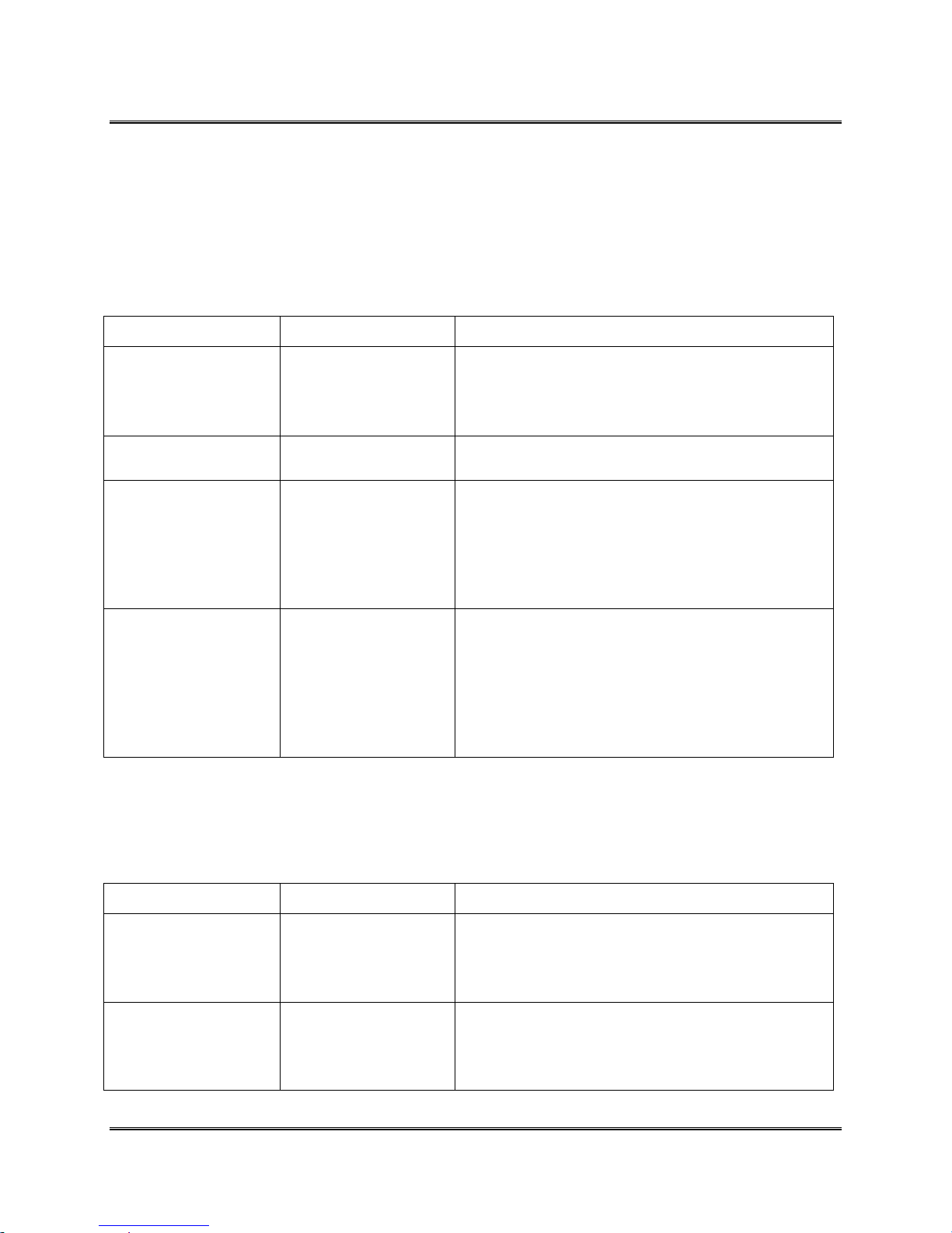
Printer Menu System
Conveyer Signal line [Pin 2]. Reference the Schematic for the pins to use when connecting to the
Conveyer Port.
9. PRE-PURGE
Use this option to keep the print heads from drying out and to clear the inkjet nozzles
automatically while operating the printer.
Menu Items Selections Explanation
A. Purge at
Start
B. Periodic
Purge
C. Purge
Interval
D. Nozzle Keep
Alive
10. FEED GAP
Disable or
Enable
Disable or
Enable
020 – 240
seconds
Disable or
Enable
If you have long breaks of twenty seconds or more
before starting another batch of records this option
will purge on the first piece before printing the
records.
This option will activate the periodic purge.
This option will purge the ink cartridges at timed
intervals on a piece. Set the time to determine when
to purge the ink cartridges. The feeder will pause for
a few seconds after the purge pattern is printed.
Each timed interval begins from the last purge print
pattern.
This option will randomly purge the individual
nozzles of the print cartridges to keep the ink from
clogging the nozzles and to create a virtually
invisible pattern of dots on the media. The printer
will continually purge except when another prepurge is pending and while the records are being
printed.
Two settings are available to modify how the printer reacts Use this option to help when feeding
very glossy media or short media. (Only available with the Bryce Feeder Assembly)
Menu Items Selections Explanation
A. Selectable
Gap
B. Stream Feed
3.10 in to
12.70 in
Press the [Enter]
button to enable this
option and disable
the Selectable Gap.
Revision C 30K USERS MANUAL Section 6 - 15
P/N 90-00203-001
This item increases the gap or space between pieces
of media as it is fed through the printer. Increasing
the gap will slightly reduce the overall throughput of
the printer.
This option gives the each record a fixed time before
printing on the next piece. This option is best used
to print small records of three or less lines of text.
Page 55
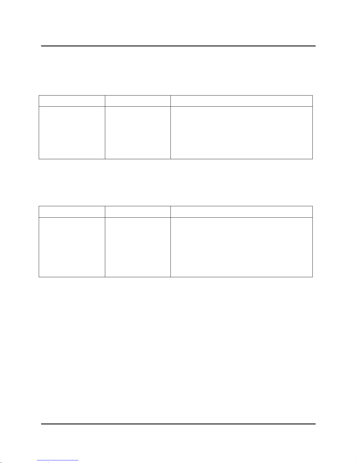
Printer Menu System
11. ROM REVISION#
This option displays the Firmware Revision installed in the printer and the total number of
accumulated print cycles (maintenance count).
Menu Items Selections Explanation
Press the [Test] button
when ROM REV. is
displayed on the LCD.
A list of the Main
Menu and Setup Menu
settings is printed on
four pieces of media.
The LCD display will give a momentary view of the
ROM Revision and the Maintenance count.
12. PRINT HEAD SIZE
Enable this option for the printer to keep track of the ink usage for the HP 51645A ink cartridges
or the ink reservoir system.
Menu Items Selections Explanation
Normal Capacity
or Extended
Capacity
Select the type of Print Cartridge being used with
the printer. Changing the Print Head Size alters how
the percentage of ink used is calculated for the menu
item 12. RESET INK COUNT. Note: The reservoir
system is nine times the volume of a HP 51645A ink
cartridge.
Revision C 30K USERS MANUAL Section 6 - 16
P/N 90-00203-001
Page 56
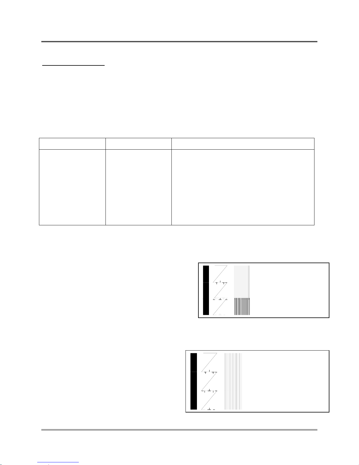
Printer Menu System
A
A
SERVICE MENU
Use this menu for adjusting the print heads in each bank, the banks to each other, checking the transport
and sensors and testing the display for proper functionality. The menu options that are preceded with a
star or Asterisk (*) are the printers’ current settings.
1. ADJUST PRINT
The following steps are for synchronizing the Print Cartridges on the 3 Head Print Assembly (Bank A)
and the 3 Head Print Assembly (Bank B). Employ the options I. BANK A to BANK B to help in
combining the 3 Head Print Assemblies for printing together or separately.
Menu Items Selections Explanation
A. Head 2 up
down
B. Head 3 up
down
C. Head 5 up
down
D. Head 6 up
down
The following is an example of how to synchronize Print Cartridges for Bank A. The same techniques
used for Bank A can be applied to Bank B.
Example:
Print out an adjust print Test Pattern by pressing the
[Test] button while in the Adjust Print menu. The printer
will print a Test Pattern like the example to the right.
280 to 300
Press the [Test] button
to print out a Test
Pattern. Check the
Test Pattern to
determine which Print
Cartridges are in need
of Vertical
Synchronization.
Use options A through D to vertically synchronize
the individual Print Cartridges in Bank A and Bank
B.
Head 1 Ban k A
Head 2 Ban k A
In this example the crooked line in the center indicates
Print Cartridge #3 has to have the printer perform a
vertical print adjustment. The example shows Print
Cartridge #3 is too high.
Head 3 Ban k
Scroll through the Adjust Print menu options until the HEAD 3 UP DOWN option is displayed on the
LCD panel.
Enter the menu option to move the setting down.
Enter the new value into the printers memory. An
Asterisk (*) will appear in front of the new selection.
Press the [Test] button to print another Test Pattern.
The Test Pattern is printed using the entered
selection.
When the correct numeral is selected the center Test
Pattern will be one long crooked line with hatch
marks like the example to the right.
Revision C 30K USERS MANUAL Section 6 - 17
P/N 90-00203-001
Head 1 Bank A
Head 2 Bank A
Head 3 Bank
Page 57
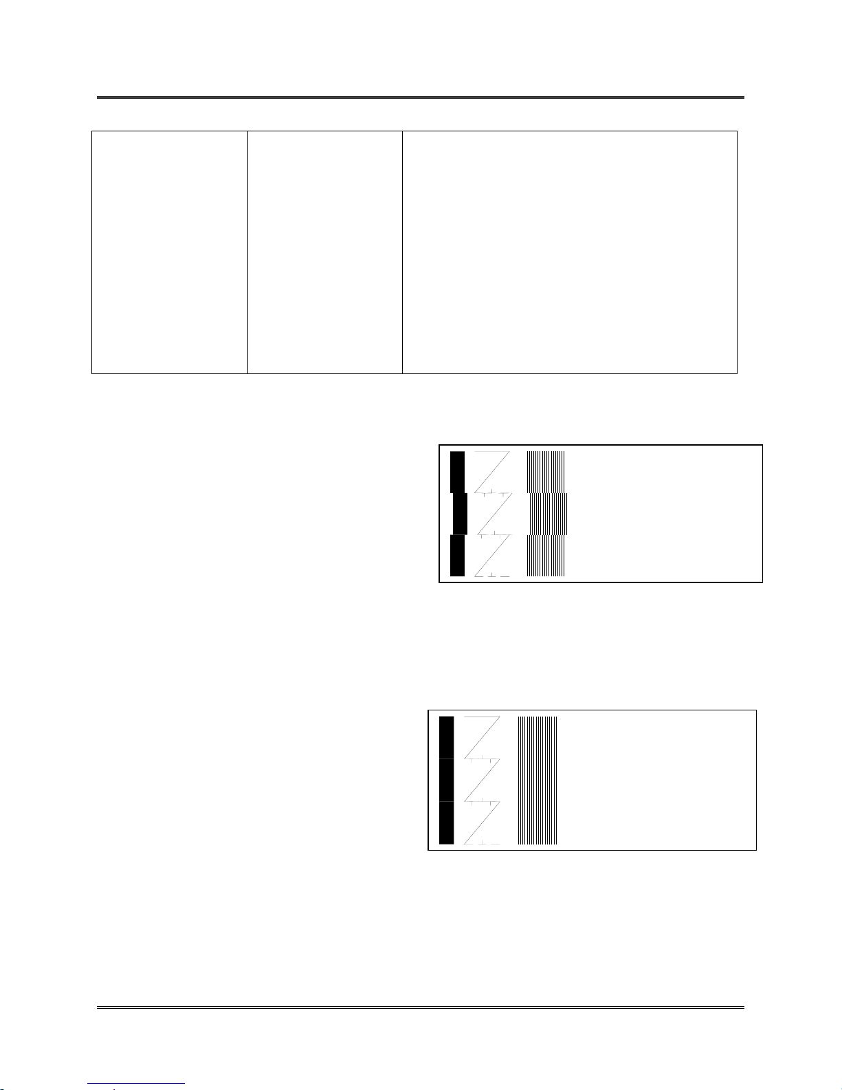
Printer Menu System
A
A
A
A
E. Head 2 side
to side
F. Head 3 Side
to Side
G. Head 5 Side
to Side
H. Head 6 side
to side
The following is an example of how to synchronize Print Cartridges for Bank A. The same techniques
used for Bank A can be applied to Bank B.
Example:
Print out an adjust print Test Pattern by pressing the
[Test] button while in the Adjust Print menu. The
printer will print a Test Pattern like the example on
the right.
In the example to the right the wide vertical line on
the left and 18 thin vertical lines indicate Print
Cartridge #2 needs a horizontal print adjustment. The
example shows Print Cartridge #2 is to far to the
right.
01 to 99
Press the [Test] button
to print out a Test
Pattern. Check the
Test Pattern to
determine which Print
Cartridges are in need
of horizontal
Synchronization.
Use the options E through H to horizontally
synchronize the individual Print Cartridges in Bank
A or Bank B.
When a line of print is split apart or the left edge of
a block of lines don’t line up with the left edge of
the other lines the Print Cartridges have to be
synchronized horizontally. Perform a horizontal
adjustment whenever the wide solid line and the set
of 18 thin vertical lines do not form long vertical
lines for the whole bank of Print Cartridges.
Head 1 Bank A
Head 2 Bank
Head 3 Bank A
Scroll through the Adjust Print menu options until the HEAD 2 SIDE TO SIDE option is displayed on the
LCD panel. Select this menu item to change the settings.
Press the [-] button to scroll the values down and move Head 2 left.
Press the [Enter] button to select the desired value. An Asterisk (*) will appear in front of the new
selection.
Press the [Test] button to print another Test Pattern.
This time the Test Pattern is printed using the
entered selection.
When the correct numeral is selected the wide line
and the set of 18 vertical lines form long vertical
lines down the entire Bank A of Print Heads.
Revision C 30K USERS MANUAL Section 6 - 18
P/N 90-00203-001
Head 1 Bank
Head 2 Bank
Head 3 Bank
Page 58
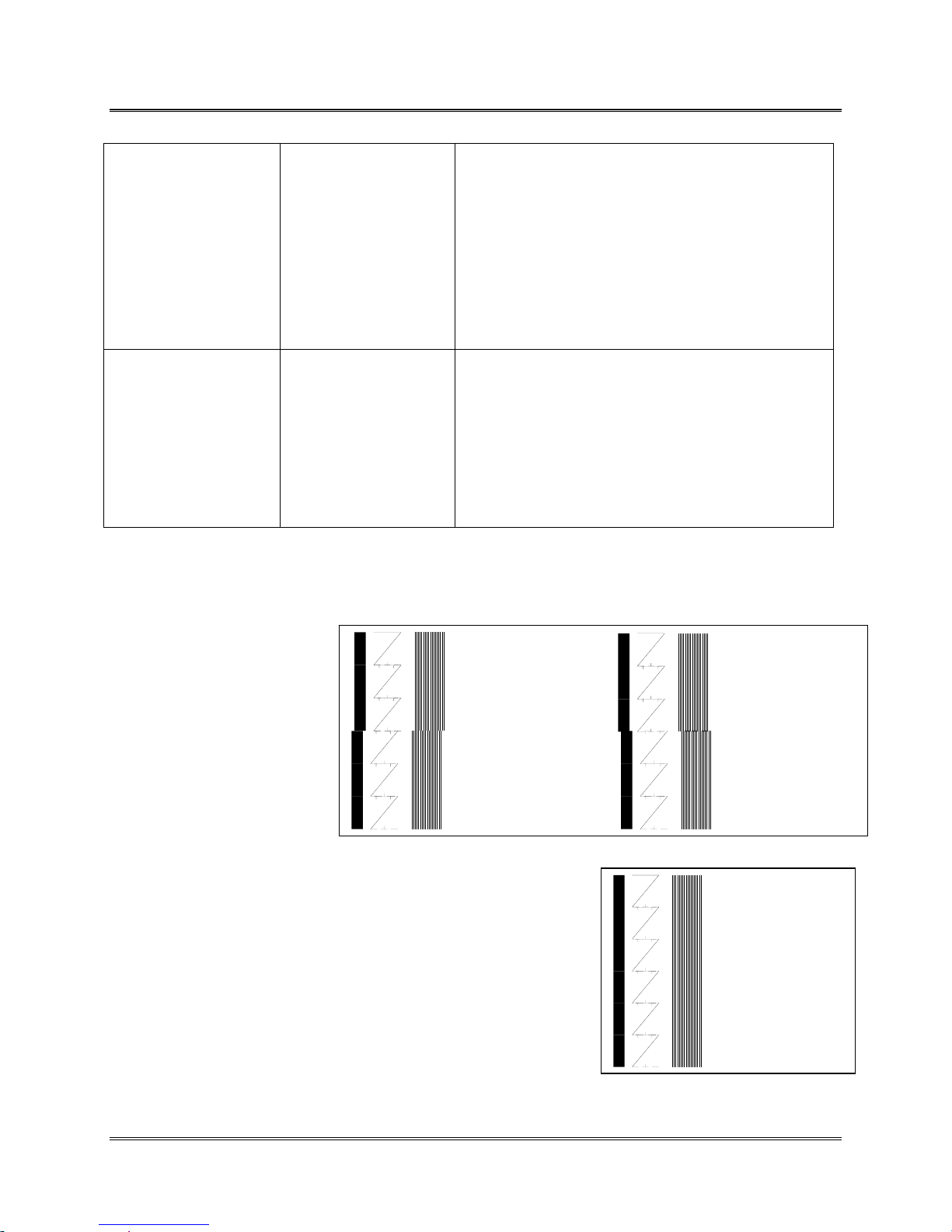
Printer Menu System
A
A
A
I. Bank A to
Sensor
00.500 to 36.000
Press the [Test] button
to print out a Test
Pattern. Check the
Test Pattern to
determine where
Banks A is printing on
the media.
Use this option to set this distance between the
sensor and the first head in bank A.
Set each Bank of Print Heads to work together
(synchronized) or to work independently in different
locations on the media. Check the Test Pattern to
determine which Banks are in need of
synchronization or for relocating the position of a
bank on the media.
I. Bank B to
Sensor
For ease of illustration the following example will deal with synchronizing Bank A and Bank B together.
It is assumed the Banks of Print Heads have already been mechanically aligned next to each other
Example:
Print out an adjust print Test
Pattern by pressing the [Test]
button while in the Adjust
Print menu. The printer will
print a Test Pattern like the
example on the right. The
adjust print Test Pattern
consists of three rows of
different patterns, the first
wide line and the eighteen
vertical lines are used for
synchronizing Bank A and
Bank B.
When the two pattern do not match to form long vertical lines,
perform the following steps. In the example to the right the wide
vertical line on the left and 18 thin vertical lines indicate Bank B
needs a horizontal print adjustment. Rule of Thumb: Take the
distance from the previous bank of print heads that want to align the
next bank with and add 3.5 inches. As an example if Bank A is 7.000
then Bank B starts at 10.500.
Press the [Enter] button to select the desired value. An Asterisk (*)
will appear in front of the new selection.
00.500 to 36.000
Press the [Test] button
to print out a Test
Pattern. Check the
Test Pattern to
determine where
Banks B is printing on
the media.
Use this option to set this distance between the
sensor and the first head in bank B.
Set each Bank of Print Heads to work together
(synchronized) or to work independently in different
locations on the media.
Head 1 B ank A
Head 2 B ank A
Head 3 B ank A
Head 4 B ank B
Head 5 B ank B
Head 6 B ank B
Head 1 B ank A
Head 2 B ank A
Head 3 B ank A
Head 4 B ank B
Head 5 B ank B
Head 6 B ank B
Head 1 Bank
Head 2 Bank
Head 3 Bank
Head 4 Bank B
Head 5 Bank B
Head 6 Bank B
When correct all vertical lines should be straight.
Revision C 30K USERS MANUAL Section 6 - 19
P/N 90-00203-001
Page 59
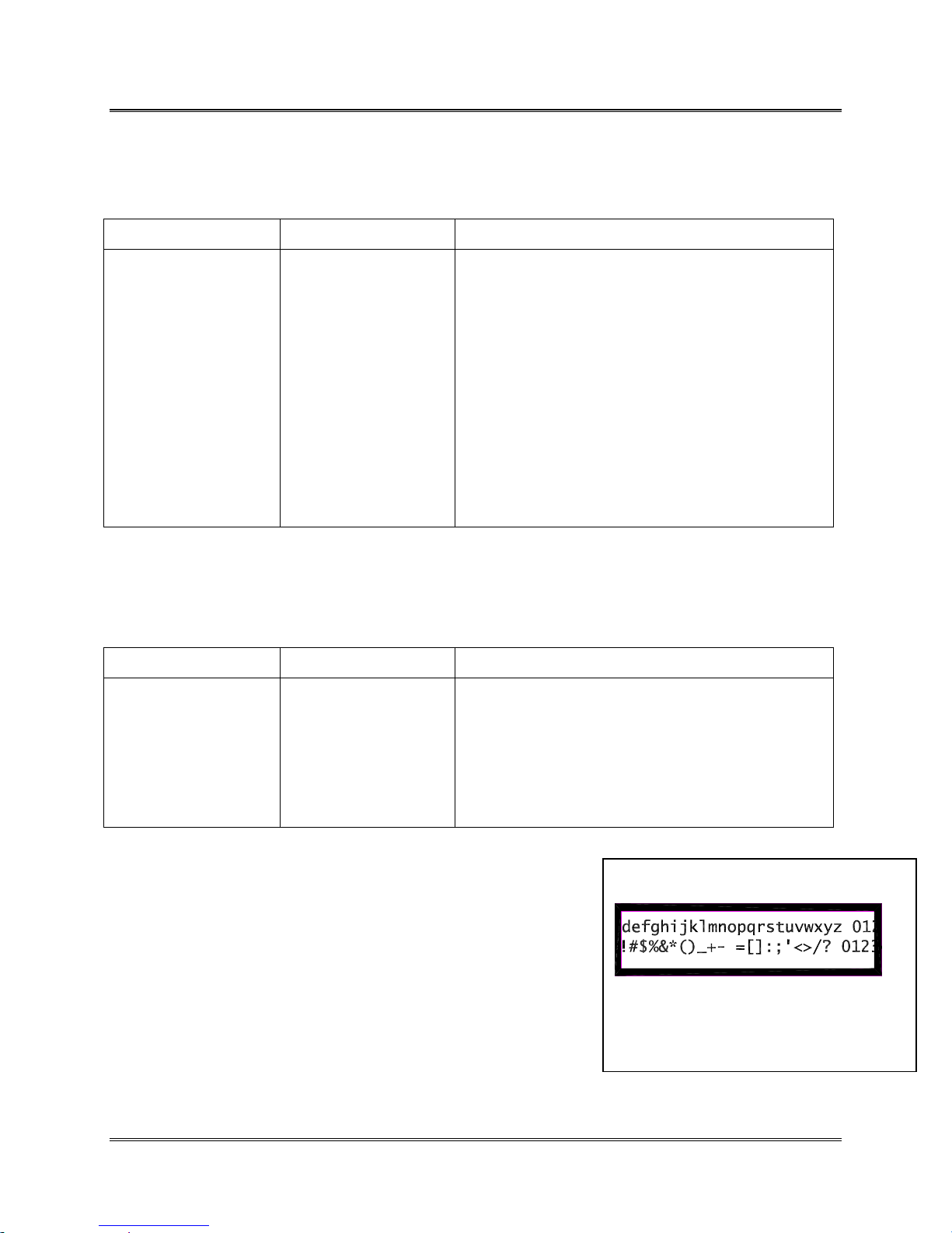
Printer Menu System
2. TEST SYSTEM
Use this option to check the mechanical and / or electrical operation of the Address Printer.
Menu Items Selections Explanation
Press the [Enter]
button to select this
option. As soon as, the
[Enter] button is
pressed, the printer
will be in the test
mode.
To test the motor,
press the [+] button to
start increasing the
motor speed or [-]
button to decrease the
speed.
The sensor is represented on the LCD by the
lowercase letter p or the upper case letter P. The
LCD display shows a lower case letter of p (sensor
unblocked) when the sensor is clear. When the
sensor has media in the path the capitol letters P
(sensor blocked) is shown. When a Feeder
Assembly is attached the Feeders’ motor can also be
tested. Press the [Enter] button to select between the
BELT (printer motor) or FEEDER (Feeder motor)
options. An asterisk will appear before the selected
option.
3. TEST DISPLAY
Use the test display option to help determine if the LCD display is not functioning properly i.e. missing
characters, strange characters, missing segments, etc.
Menu Items Selections Explanation
Press the [Enter]
button to select this
option. As soon as, the
[Enter] button is
pressed, the printer
will be in the test
mode.
The test display will scroll characters across the top
and bottom of the LCD display.
EXAMPLE:
The LCD display will scroll the lower case alphabet and numerals (0-
9) across the top line, while the bottom line will scroll control
characters and the numerals. The Test function will cycle twice and
return to the Service Menu. See example below for LCD display
sample test message.
abcdefghijklmnopqrstuvwxyz 0123456789
\->!#$%&*()_+- =[]:;'<>/? 0123456789
Revision C 30K USERS MANUAL Section 6 - 20
P/N 90-00203-001
Example of LCD display with
characters scrolling across
Page 60
Troubleshooting and Diagnostics
Users Manual Symptoms & Solutions Chart
SYMPTOM
Nothing happens when
power is switched on
Display Problem (Blank
LCD display).
LCD display shows
miscellaneous Chinese
characters.
LCD display shows solid
black boxes or
miscellaneous characters
Motor on, Transport Belt
doesn't turn
(Motor Stall Error) Media Jammed
Motor runs for a moment,
turns off, LCD display
indicates
(Motor Stall Error)
No Power to printer.
Fuse is blown
Bad LCD Call Service Representative.
Bad LCD
Bad Processor Main Board
Bad Print Head Assembly
Loose set screw on Motor
Drive Pulley.
Broken belt
Bad motor or seized
bearing
Bad Processor Board
Bad bearing on roller or
bearing in pulley assembly.
Belt Jam
Bad Encoder or Processor
Board
CAUSE
SOLUTION
Check Power Cord. Call Service Representative.
Call Service Representative.
Call Service Representative.
Call Service Representative.
Call Service Representative.
Call Service Representative.
Call Service Representative.
Remove jammed media. Press Test button or OnLine to reset printer.
Call Service Representative
Call Service Representative
Call Service Representative
Manually fix belt by gently pulling on belt side to
side
Call Service Representative
Revision C 30K USERS MANUAL Section 7 - 1
P/N 90-00203-001
Page 61
Troubleshooting and Diagnostics
SYMPTOM
Printer keeps stopping and
starting every few pieces.
Envelope jams
(Paper Jam Error )
Print Quality Problems
(No print)
Non Uniform Print Quality Print Cartridge not
Ink Streaking on Media Print Head Holder
Postal Bundle Pause is
enabled or set incorrectly.
The SOH character is
being sent to the printer.
Media out of spec.
Print Head Holder
Assemblies set to low for
this media.
Ink Jet Cartridge problems
Printing on belts or floor,
address location set off the
media
Print Head Holder broken
Sensor is dirty.
installed right
Print Head Holder broken
Assemblies set to low for
this media.
Adjustable wipers set
incorrectly
CAUSE
SOLUTION
Disable Postal Bundle Pause or correct the
settings.
Do a HEX Dump of the problem addresses.
Examine for a SOH character (01) in the data.
Remove the SOH character from the data.
Minimum thickness of media is 0.003” (0.00762
cm).
Turn the Control Knob to raise up the Print Head
Holder Assemblies.
Purge ink jet cartridge.
Clean cartridge with soft cotton cloth and water.
Change to a known good cartridge.
Correct position with Address Layout Menu
Call Service Representative.
Clean sensors with canned air or soft cotton cloth.
Take the Print Cartridge out and reinstall into
Print Head Assembly.
Call Service Representative.
Turn the Control Knob clockwise to raise the
Print Head
Move wipers to area without ink.
Revision C 30K USERS MANUAL Section 7 - 2
P/N 90-00203-001
Page 62
Troubleshooting and Diagnostics
SYMPTOM
Ink Print Quality is not
sharp
Ink Print Quality problem.
White stripes or lines
through print.
Print Quality Problem
(blanks between printed
media)
Print Quality Problems
(Gray Print)
Print Quality Problems
(Characters are Printing
Twice)
CAUSE
Print Head Holder
Assemblies set too high.
Media unsuitable
Print Cartridge almost
empty. (LED is blinking)
Dried ink clogging nozzles
on Print Cartridge.
Pins bent or broken on
Print Head Holder.
Bad Board or Flex Circuit.
Wrong setting in Lines Per
Address.
Sending media to quickly
Faulty or dirty sensor.
Print Cartridge almost
empty. (LED is blinking)
Print Head Holder
Assemblies set too high
Incorrect Software Driver
Bad or damaged Encoder
SOLUTION
Turn the Control Knob counterclockwise to raise
the Print Heads
Change to a typical white wove bonded paper
Replace Print Cartridge
Purge Print Cartridge.
Clean cartridge with soft cotton cloth and water.
Change to a known good cartridge.
Call Service Representative.
Call Service Representative.
Increase settings in Lines Per Address to match
software.
Slow the speed the media is sent to printer.
Clean sensors with canned air or soft cotton cloth.
Ink supply too low, Replace Print Cartridge
Turn the Control Knob counterclockwise to lower
the Print Head
Use 24K/30K driver or dump printer interface
(TTY, Teletype, DOS text printer, Generic
printer) or use Bryce 10K, Bryce 7600, P.B.
W800 and P.B. W600.
Call Service Representative.
Revision C 30K USERS MANUAL Section 7 - 3
P/N 90-00203-001
Page 63
Troubleshooting and Diagnostics
SYMPTOM
Print Quality Problems
(Unwanted Bolding)
Print Quality Problems
(Addresses "walking") to
next piece
Interface problems
(Garbage print)
Interface problems
(Losing characters & lines)
Overrun Error
(Error Message)
CAUSE
Main Menu setting of Bold
is enabled
ESC sequence turning bold
on, located before the
address
Number of lines of address
varies. No Form Feed used
for address termination.
Incorrect Software Driver
Wrong Symbol Set
selected in printer.
Bad communications Cable
Bad main processor board
Centronic (Parallel) over
maximum length
Incorrect Software Driver
Bad communications Cable
or CPU I/O
SOLUTION
Press Test Button. A bold Standard Bryce Office
Systems Address is printed. Turn Bold setting off
in Main Menu.
Do a HEX Dump of the problem address.
Examine for ESC sequence (1B) before the start
of the line. Reference printer command codes to
find ESC Sequence. Remove the ESC Sequence
from the address.
Do Hex Dump, count carriage returns (0D in
hexadecimal code), and line feeds (0A in
hexadecimal code). Set Address Setup in Setup
Menu accordingly. If address ends with a form
feed (0C in hexadecimal code). Set address setup
to match the number of lines to Address Setup.
Use 24K/30K driver or dump printer interface
(TTY, Teletype, DOS text printer, Generic
printer) or use Bryce 10K, Bryce 7600, P.B.
W800 and P.B. W600.
Select correct Symbol Set from printers Setup
Menu.
Replace internal or external cable
Call Service Representative.
Replace parallel cable, maximum length 10 feet
(304.8 cm)
Use 24K/30K driver or dump printer interface
(TTY, Teletype, DOS text printer, Generic
printer) or use Bryce 10K, Bryce 7600, P.B.
W800 and P.B. W600.
Replace cable or Call Service Representative.
Revision C 30K USERS MANUAL Section 7 - 4
P/N 90-00203-001
Page 64
Troubleshooting and Diagnostics
SYMPTOM
Parallel Interface, printer is
not printing (Printer
Halted)
Invalid Font Sig,
(Error Message)
Invalid Font CS,
(Error Message)
No Font Found
(Error Message)
Out of Memory
(Error Message)
Q1 Out of Memory
(Error Message)
Q2 Out of Memory
(Error Message)
Graphic Too Complex
(Error Message)
Bad PCL Command
(Error Message)
Print Hd A Error
(Error Message)
Print Hd B Error
(Error Message)
CAUSE
Bad data sent
Bad communications Cable
Bad main processor board
Centronic (Parallel) Cable
over maximum length
Incorrect Software Driver
Signature of Font is
invalid.
Checksum on Font is
invalid.
Font is invalid. Turn printer off, then turn printer on and send
Overuse of graphics / page
information
Problems with too much
Page information
Problems with too much
Page information
Overuse of graphics / page
information
Incorrect PCL command
received.
Problems communicating
to Bank A
Problems communicating
to Bank B
Turn printer off, then turn printer on and send
again.
Replace parallel cable, maximum length 10 feet
(304.8 cm)
Call Service Representative.
Replace parallel cable, maximum length 10 feet
(304.8 cm)
Use 24K/30K driver or dump printer interface
(TTY, Teletype, DOS text printer, Generic
printer) or use Bryce 10K, Bryce 7600, P.B.
W800 and P.B. W600.
Turn printer off, then turn printer on and send
again. If problem persists then call Service
Representative.
Turn printer off, then turn printer on and send
again. If problem persists then call Service
Representative.
again. If problem persists then call Service
Representative.
Turn printer off then send again.
Turn printer off then send again. Slow down
feeder.
Turn printer off then send again. Slow down
feeder.
Turn printer off then send again.
Turn printer off then send again. Remove bad
PCL command from record.
Turn printer off then send again. If problem
persists then call Service Representative.
Turn printer off then send again. If problem
persists then call Service Representative.
SOLUTION
Revision C 30K USERS MANUAL Section 7 - 5
P/N 90-00203-001
Page 65
Troubleshooting and Diagnostics
SYMPTOM
Print Head Error #1
Bank(s) A B
(Error Message)
Different Print Head
Types in each bank
(Error Message)
Battery Error
(Error Message)
No Barcode Invalid Zip Code or more
No Planet Code Printed Invalid Code or more data
Notes: ___________________________________________________________________________________
_________________________________________________________________________________________
_________________________________________________________________________________________
_________________________________________________________________________________________
_________________________________________________________________________________________
_________________________________________________________________________________________
_________________________________________________________________________________________
_________________________________________________________________________________________
_________________________________________________________________________________________
_________________________________________________________________________________________
_________________________________________________________________________________________
Problems communicating
to both Bank A & B
Problems communicating
to one or the other Banks
of Print Heads
Mixed a new style of Print
Head Holder Assembly
with an old style of Print
Head Holder Assembly.
Battery is low and cannot
maintain the printers’
settings when powered
down.
data following Zip Code.
Five (5) Digit Zip Code
turned off.
following the PLANET
Code.
CAUSE
SOLUTION
Turn printer off then send again. If problem
persists then call Service Representative.
Turn printer off then send again. If problem
persists then call Service Representative.
Bank A & Bank B must be the same style of Print
Head Holder Assembly. Call Service
Representative.
Call Service Representative.
Check Zip Code and correct, remove any data
following the Zip Code. (See Appendix H for
valid DPBC format)
The 5 digit zip code option in the print Main
Menu is Off.
Check Planet Code and correct, remove any data
following the PLANET Code. (See Appendix H
for valid PLANET code format)
Revision C 30K USERS MANUAL Section 7 - 6
P/N 90-00203-001
Page 66
Troubleshooting and Diagnostics
Symptoms and Solutions when using the Bryce Feeder
SYMPTOM
Transport Belt turning,
Feed Rollers won’t turn.
(Paper Out Error)
Early Feed Error
(Error Message)
Stream Feeding of the
media
(Early Error Message)
Feeder is not sending
media consistently.
(Intermittent feed problem)
CAUSE SOLUTION
Feeder connector is loose.
Loose set screw on pulley
or gears not engaging.
Bad Feeder Motor or
Loose pulley.
Faulty or dirty sensors
Thickness of Separator “H”
Block is set to high
Feed Gap is too short for
the media.
Faulty or dirty sensor.
Feed Roller is not stopping.
Thickness adjustment set
incorrectly
Stack of media is too
small.
Feed Rollers glazed or
contaminated with paper
dust.
Feed Ramp Assembly and
Media Support Wedge is
positioned or being used
incorrectly.
Feed Rollers worn down
Disconnect Feeder and reattach to Printer.
Call Service Representative
Call Service Representative
Clean sensors with canned air or soft cotton cloth.
Call Service Representative.
Reset the height of the Separator “H” Block.
Increase the setting in the Feed Gap menu
Clean sensors with canned air or soft cotton cloth.
Call Service Representative.
Adjust the Separator “H” Block according to
users manual.
Place a larger stack of media on Feed Rollers.
Clean with water and plastic scouring pad.
Reposition Feed Ramp Assembly and Media
Support Wedge to transfer the weight of media
onto Feed Rollers.
Replace Front or Rear Feed Rollers.
Revision C 30K USERS MANUAL Section 7 - 7
P/N 90-00203-001
Page 67
Troubleshooting and Diagnostics
SYMPTOM
CAUSE SOLUTION
Feeder is not sending
media to Printer
(Paper Out Error Message)
Envelope jams
(Paper Jam Error )
Printer runs for a moment,
turns off, LCD display
indicates
(Feeder Stall Error)
Print looks skewed Setup of Feeder Assembly
Thickness adjustment set
incorrectly
Stack of media is too
small.
Feed Rollers glazed or
contaminated with paper
dust.
Feed Ramp Assembly and
Media Support Wedge is
positioned or being used
incorrectly.
Feed Rollers won’t turn
Media out of spec.
Media sticking together.
Media out of spec.
Media sticking together.
Bad bearing on roller or
bearing in pulley assembly.
Belt Jam
Bad Encoder or Processor
Board
Bad motor
for the media is incorrect.
Adjust the Separator “H” Block according to
users manual.
Place a larger stack of media on Feed Rollers.
Clean with water and plastic scouring pad.
Reposition Feed Ramp Assembly and Media
Support Wedge to transfer the weight of media
onto Feed Rollers.
Call Service Representative.
Minimum thickness of media is 0.003” (0.00762
cm). Maximum thickness of media is 0.5” (1.27
cm)
Fan media before placing on Feed Rollers.
Maximum thickness of media is 0.5” (1.27 cm)
Fan media before placing on Feed Rollers.
Call Service Representative
Call Service Representative
Call Service Representative
Call Service Representative
Redo the media setup with the Feeder Assembly.
See Section 5.
Revision C 30K USERS MANUAL Section 7 - 8
P/N 90-00203-001
Page 68

Troubleshooting and Diagnostics
Notes: ___________________________________________________________________________________
_________________________________________________________________________________________
_________________________________________________________________________________________
_________________________________________________________________________________________
_________________________________________________________________________________________
_________________________________________________________________________________________
_________________________________________________________________________________________
_________________________________________________________________________________________
_________________________________________________________________________________________
_________________________________________________________________________________________
_________________________________________________________________________________________
_________________________________________________________________________________________
_________________________________________________________________________________________
_________________________________________________________________________________________
Revision C 30K USERS MANUAL Section 7 - 9
P/N 90-00203-001
Page 69
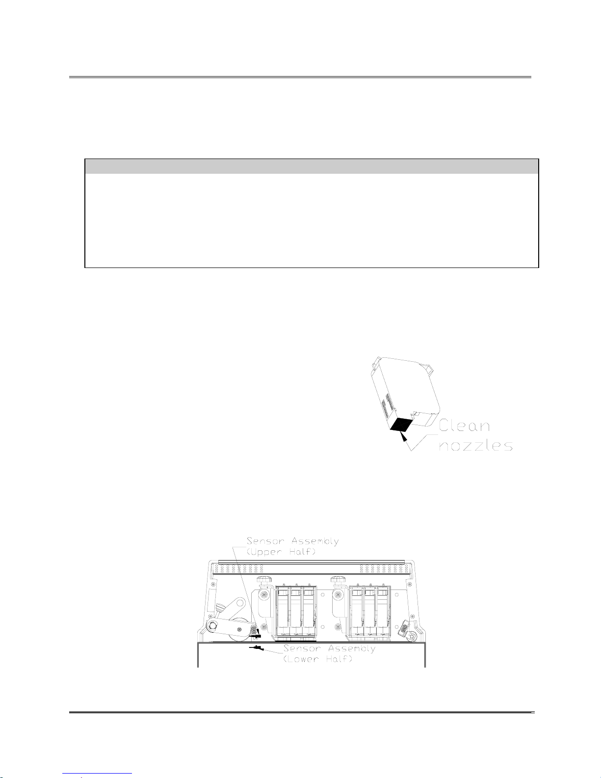
Cleaning and Maintaining the Printer
The 30K Printer is designed for trouble free service with a
minimal amount of care. Periodic cleaning of the Sensor,
Transport Belts, Floor and 3 Print Head Assemblies will be
necessary.
CAUTION!!
CLEAN PRINT CARTRIDGE, INK SURFACES AND COVERS WITH PLAIN WATER.
ALL METAL AND PLASTIC CAN BE CLEANED WITH ISOPROPYL, DENATURED & RUBBING
ALCOHOL OR WATER ONLY.
USING ANY OTHER CLEANING SOLVENTS WILL VOID ALL WARRANTIES.
Keep cleaning solvents with petroleum based products from rubber or plastic parts.
If the print quality is unacceptable select the Purge Print Head
function from the Main Menu (See Section Purge Print Head).
If problems still persist then do the following:
• Remove the Print Cartridge (See Section
Remove Print Cartridges). Clean the nozzles
with a soft cotton cloth. Use a dry cloth
or one moistened with alcohol to clean
the ink jet cartridge.
• Remove problem print cartridge and
install a new print cartridge.
Perform a self cleaning (Purge Print Head) cycle at the
start before printing and periodically while printing to
keep the nozzles clear of dry ink and debris.
Preventative
Maintenance:
Cleaning
the print
cartridges
With use, a film and/or dust builds up on the eye of the sensor
causing misfeeds of media. Periodically use compressed air to
blow dust from the sensors. For caked on dust use a Q-tip to
remove the dust from the eye of the sensor. Note: The lower
half of the Sensor is
seen through the hole
in the floor.
Revision C 30K USERS MANUAL Section 8 -
P/N 90-00203-001
Cleaning
the Photo
Sensor
Assembly
1
Page 70
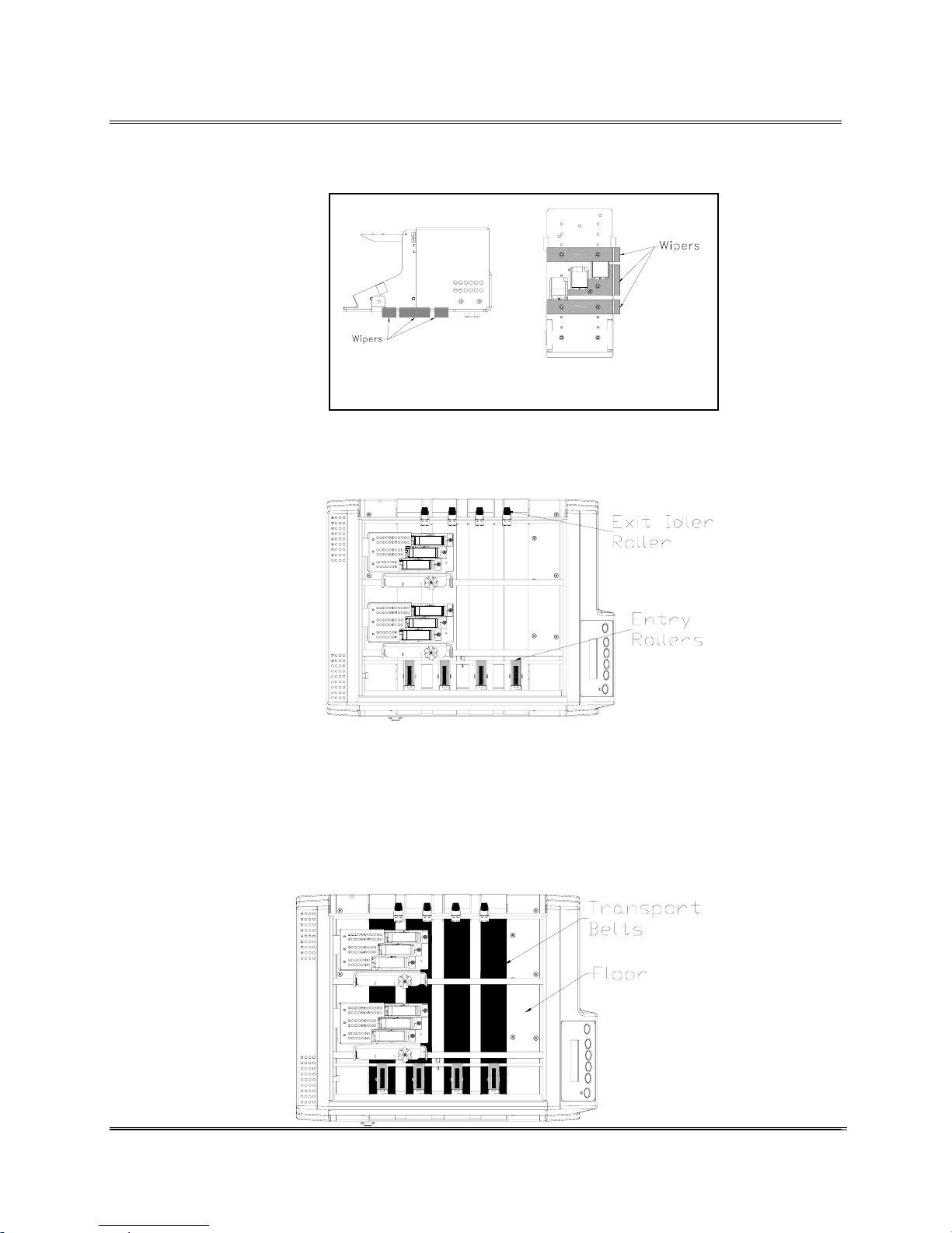
Cleaning and Maintaining the Printer
The Wipers beneath the banks of Print Head Assemblies will
over time pick up ink,
wax, clay and other
material from the media it
touches. Once enough wax
or clay, etc, accumulates
on the wipers it will leave
marks or smears on the
media. Use water to
dampen a soft cloth to
remove any ink, wax, clay,
etc. and keep the wipers
clean.
When the Exit Idler
Roller is adjusted over
the area where
addresses are printed
the ink will get
transferred from the
media onto the roller.
Use water to dampen a
soft cotton cloth to
remove the ink from the
rollers.
Ink will get sprayed on the Transport Belts and the Floor
Assembly from all the purging, setting up and printing
records, etc. Eventually an adequate amount of ink will
accumulate on top of the Transport Belts to give the belts a
glossy sheen. Use water to dampen a soft cotton cloth to
remove the ink from
the Transport Belts
and the Floor
Assembly. Raise the
Print Head
Assemblies up and
out of the way to
clean the Floor
Assembly.
Side View
Bottom View
Cleaning
the Wipers
Cleaning
the Exit
Idler Roller
& Entry
Rollers
Cleaning
the
Transport
Belts and
Floor
Assembly
Revision C 30K USERS MANUAL Section 8 -
P/N 90-00203-001
2
Page 71
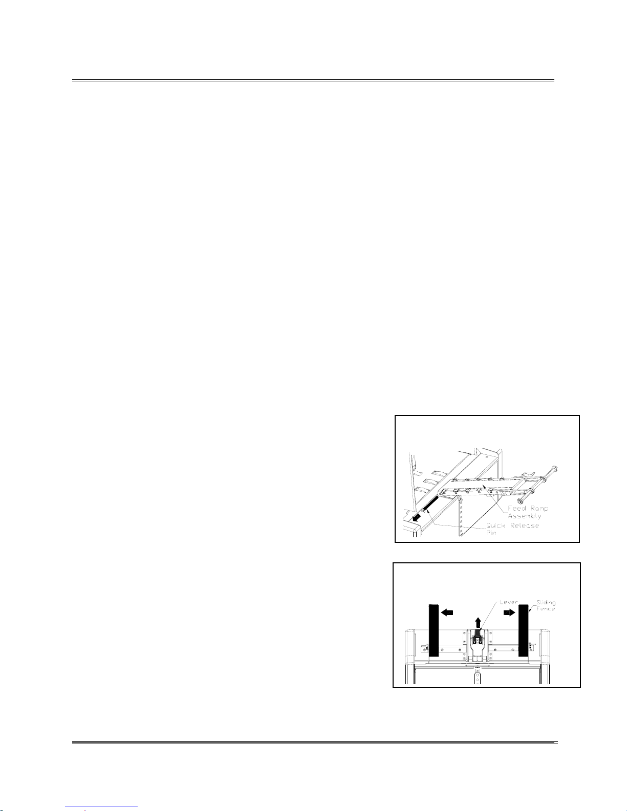
Cleaning and Maintaining the Printer
Lint and paper dust will tend to build up on the feeders tires
with use. Clean the tires as needed: when it is glazed or has
yellowish residue. Use alcohol to dampen a soft cotton cloth
or plastic scouring pad to clean all rubber tires.
The tires or sections of the tires will wear down differently
depending on the variety of media used and where the areas of
heavy use are. If cleaning the tires is ineffective in helping to
feed the media into the printer, then reference the replacement
procedures for the worn Tires on the Upper or Lower Feed
Roller Shaft Assembly. (See Replacing the Tires on the Feeder
Assembly)
Cleaning the Tires
on the Feeder
Assembly
Replacing the Tires
on the Feeder
1. Lift the Feeder Assembly to unhook it from the
printer. Pull the Feeder Assembly away from the
printer.
Assembly
2. Disconnect the Feeder Information Cable Assembly
from the Printer.
3. Remove the Quick Release Pin from the Feeder
Assembly to disconnect the Feed Ramp Assembly
from the Floor. Lower the Feed Ramp out of the way.
4. Push the Latch up to raise the Separator H-Block to the
uppermost position and secure in place.
5. Pull the Sliding Fences wide open on the Feeder
printer.
Pull the Quick Release Pin from
the Feeder Assembly.
Lift Lever up and open Sliding
Fences.
Revision C 30K USERS MANUAL Section 8 -
P/N 90-00203-001
3
Page 72
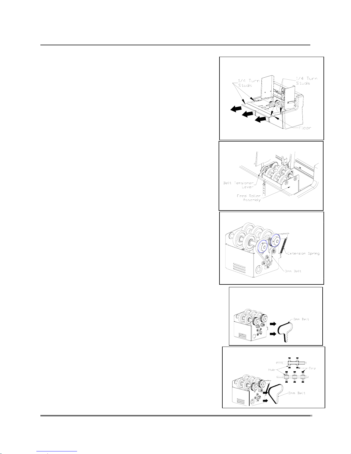
Cleaning and Maintaining the Printer
6. Using a regular screwdriver, release the four 1/4 Turn
Studs on the Floor. Turn each stud counterclockwise a
quarter turn. Note: The four 1/4 Turn Studs are
permanently attached and cannot be removed.
Slide Floor beneath Sliding
Fences.
7. Lift the Floor. Unhook the front of the floor and slide
it beneath the Sliding Fences.
8. Reference figure to right. Located inside is the Feed
Roller Assembly. From the side of the assembly,
release the Extension Spring from the Belt Tensioner
Lever.
9. Remove the 3 mm Belt from around the two Feed
Pulleys. Note: The Feeder Assembly with two Idler
Pulleys located in the center uses the Old Style belt.
10. Pull the Upper or Lower Feed Roller Shaft Assembly
from the printer. A bearing will come out with the
feeder shaft assemblies. Remove these parts from the
printer.
Release Extension Spring.
Walk belt off Feed Pulleys
Pull the Tires off the hubs.
(Old Style Belt)
11. The Tires may now be removed by pulling them from
the hubs.
12. Replace in reverse order.
Revision C 30K USERS MANUAL Section 8 -
P/N 90-00203-001
Pull the Tires off the hubs.
4
Page 73
Revision C 30K USERS MANUAL Section A - 1
P/N 90-00203-001
Appendix A • Bryce Office Systems 30K MAIN MENU Flow Chart
----MAIN MENU----
1. Address Layout
Address Layout
A
. Dist From Left
DIST FROM LEFT +MORE
*4.50 in -LESS
DIST FROM LEFT +MORE
*115 mm -LESS
Address Layout
B Dist From Top
DIST FROM TOP +MORE
*0.00 in -LESS
DIST FROM TOP +MORE
*00 mm -LESS
Address Layout
C. Line Spacing
LINE SPACING
3 lines/inch
LINE SPACING
4 lines/inch
LINE SPACING
6 lines/inch
LINE SPACING
8 lines/inch
LINE SPACING
*Automatic
Address Layout
D. Orientation
ORIENTATION
*Normal
ORIENTATION
Invert
c Substituted Address Layout menu selections when ORIENTATION is in Invert.
cAddress Layout
A. Dist to Right
DIST TO RIGHT +MORE
*4.50 in -LESS
DIST TO RIGHT +MORE
*115 mm -LESS
----MAIN MENU----
2. Print Quality
Print Quality
*Executive
Print Quality
Letter
Print Quality
Draft
Print Quality
Super Draft
----MAIN MENU----
3. Font
FONT
dA. Name
FONT NAME
*Courier
FONT NAME
Sans Serif
FONT NAME
Roman
FONT NAME
Baxter
FONT NAME
Dingbat
FONT NAME
Hancock
FONT NAME
Marina
FONT NAME
Quincy
FONT NAME
Silicon
FONT NAME
Springer
FONT NAME
Stencil
FONT NAME
Windmill
FONT
B. Size
FONT SIZE +LARGER
*12 point -SMALLER
FONT
C. Width
FONT WIDTH
*Normal (100%)
FONT WIDTH
Thin (75%)
FONT WIDTH
Condensed (50%)
FONT WIDTH
Wide (125%)
FONT WIDTH
Expanded (150%)
FONT
D. Bold
BOLD
*Off
BOLD
On
FONT
E. Italic
ITALIC
*Off
ITALIC
On
FONT
F. Outline
OUTLINE
*Off
OUTLINE
On
----MAIN MENU----
4. Barcode
BARCODE
A
. Location
BARCODE LOCATION
*Off
BARCODE LOCATION
Above Address
BARCODE LOCATION
Below Address
BARCODE
B. 5 Digit On/Off
5 DIGIT BARCODE
*Off
5 DIGIT BARCODE
On
BARCODE
C. Bar Width
Bar Width +MORE
*10 dots -LESS
d To print a list of accessible fonts in their typeface, press the Test button when in the FONT menu and the
selection A. Name is displayed.
Page 74
Revision C 30K USERS MANUAL Section A - 2
P/N 90-00203-001
Appendix A • Bryce Office Systems 30K MAIN MENU Flow Chart
----MAIN MENU----
5.Address Recovery
ADDRESS RECOVERY
A
. Get Address
02: John P. Jones
Hit Recover ENTER to
NONE TO RECOVER.
ADDRESS RECOVERY
B. Clear Memory
Clear the +YES
Address Buffer? -NO
----MAIN MENU----
6. Clear Counter
Clear address +YES
(pcs) counter? -NO
Address counter
cleared. Pieces=0
----MAIN MENU----
7. Job Settings
JOB SETTINGS
A
. Load
Load Settings +MORE
from Job #3? -LESS
Printer is set for
Job #3.
JOB SETTINGS
B. Save
Save Settings +MORE
as Job #6? -LESS
Job #6 has been
saved.
----MAIN MENU----
8. Conveyer time
CONVEYER TIME + MORE
*0.00 Seconds - LESS
----MAIN MENU----
9. Image Overlay
IMAGE OVERLAY
A.First Image Overlay
Enable
FIRST IMAGE OVERLAY FIRST IMAGE OVERLAY
Exit
IMAGE OVERLAY
B.Clear Overlay
CLEAR OVERLAY
Clear
CLEAR OVERLAY
Exit
IMAGE OVERLAY
C.Print Overlay First
*Enable
PRINT OVERLAY FIRST PRINT OVERLAY FIRST
Disable
----MAIN MENU----
10. Purge Print Head
Purge print + YES
Head? - NO
----MAIN MENU----
11. Ink Count
Enter for 100% +NEXT
Hd01=100% Full -PREV
Enter for 100% +NEXT
Hd02=100% Full -PREV
Enter for 100% +NEXT
Hd03=100% Full -PREV
Enter for 100% +NEXT
Hd04=100% Full -PREV
Enter for 100% +NEXT
Hd05=100% Full -PREV
Enter for 100% +NEXT
Hd06=100% Full -PREV
Page 75
Revision C 30K USERS MANUAL Section A - 3
P/N 90-00203-001
Appendix A • Bryce Office Systems 30K SETUP MENU Flow Chart
----SETUP MENU----
1.Stop on Feed Err
STOP ON FEED ERROR
* On
STOP ON FEED ERROR
Off
----SETUP MENU----
2.Feeder Signal
FEEDER SIGNAL
.*NONE
FEEDER SIGNAL
ON/OFF CONTROL
FEEDER SIGNAL
PULSE OFF SIGNAL
FEEDER SIGNAL
ON/QUICK OFF
FEEDER SIGNAL
SIGNAL POLARITY
SIGNAL POLARITY
*Active OFF
SIGNAL POLARITY
Active ON
----SETUP MENU----
3.Lines Per Address
LINES/ADDRESS+MORE
*66 -LESS
----SETUP MENU----
4.Line Termination
LINE TERMINATION
*CR=CR, LF=LF
LINE TERMINATION
CR=CR+LF LF=LF
LINE TERMINATION
CR=CR LF=CR,LF
LINE TERMINATION
CR=CR+LF LF=CR+LF
----SETUP MENU----
5.Hex Dump Mode
HEX DUMP MODE
*Off
HEX DUMP MODE
On
----SETUP MENU----
6.Language
LANGUAGE
A
. Symbol Set
ISO CHARACTER SET
*ISO 6 ANSI ASCII
ISO CHARACTER SET
ISO 69 FRENCH
ISO CHARACTER SET
ISO 21 GERMAN
ISO CHARACTER SET
ISO 4 UK
ISO CHARACTER SET
ISO 60 NORW / DAN
ISO CHARACTER SET
ISO 11 SWED / FIN
ISO CHARACTER SET
ISO 15 ITALIAN
ISO CHARACTER SET
ISO 17 SPANISH
ISO CHARACTER SET
ISO 61 NOR / DAN
ISO CHARACTER SET
ISO 10 SWED / FIN
ISO CHARACTER SET
ISO 16 PORTUGUESE
ISO CHARACTER SET
ISO 8859
ISO CHARACTER SET
ROMAN 8
ISO CHARACTER SET
WINDOWS LATIN 1
ISO CHARACTER SET
PC 8
ISO CHARACTER SET
CP 1250
LANGUAGE
B. Inch/Millimeter
MEASUREMENT UNITS
*Inch
MEASUREMENT UNITS
Millimeter
LANGUAGE
C. Menu Language
DISPLAY LANGUAGE
*English
DISPLAY LANGUAGE
German
DISPLAY LANGUAGE
French
DISPLAY LANGUAGE
Italian
DISPLAY LANGUAGE
Spanish
DISPLAY LANGUAGE
Dutch
DISPLAY LANGUAGE
Polish
DISPLAY LANGUAGE
Japanese
----SETUP MENU----
7.Transport Speed
BELT SPEED +
*100% of maximum -
e Select one of the ASCII characters 33 to 90 to use for the Postal Bundle Break. The selected ASCII character
is displayed with a * next to the character contained in the braces.
Page 76
Revision C 30K USERS MANUAL Section A - 4
P/N 90-00203-001
Appendix A • Bryce Office Systems 30K SETUP MENU Flow Chart
----SETUP MENU----
8.Postal Bundle Brk
POSTAL BUNDLE BREAK
Enable/Disable Break
ENABLE/DISABLE BREAK
*Off
ENABLE/DISABLE BREAK
On
POSTAL BUNDLE BREAK
eBreak Character
BREAK CHAR +NEXT
*{*} -PREV
POSTAL BUNDLE BREAK
Break Char Count
CHAR COUNT +MORE
*06 -LESS
POSTAL BUNDLE BREAK
Pause Time
PAUSE TIME +MORE
*4.00 Seconds -LESS
----SETUP MENU----
9.Pre-Purge
PURGE AT START
*Disable
PURGE AT START
Enable
PERIODIC PURGE
*Disable
PERIODIC PURGE
Enable
PURGE INTERVAL +MORE
*120 Seconds -LESS
NOZZLE KEEP ALIVE
*Disable
NOZZLE KEEP ALIVE
Enable
----SETUP MENU----
10.Feed Gap
FEED GAP
Stream Feeding
FEED GAP
*Selectable Gap
FEED GAP +MORE
*4.50 in -LESS
FEED GAP +MORE
*300 mm -LESS
----SETUP MENU----
11.ROM Revision #
ROM REV = P72693 f
MAINTCOUNT=12345678
----SETUP MENU----
12.Print Head Size
Print Head Size
*Normal Capacity
Print Head Size
Extended Capacity
e Select one of the ASCII characters 33 to 90 to use for the Postal Bundle Break. The selected ASCII character
is displayed with a * next to the character contained in the braces.
f To print a list of the Main Menu, Setup Menu and Service Menu settings, press the Test button when ROM REV is
displayed.
Page 77
Revision C 30K USERS MANUAL Section A - 5
P/N 90-00203-001
Appendix A • Bryce Office Systems 30K SERVICE MENU Flow Chart
---SERVICE MENU---
1. Adjust Print
BANK A
Head 2 up down
MOVE HD 2 VERT +UP
*294 press test -DOWN
BANK A
Head 3 up down
MOVE HD 3 VERT +UP
*294 press test -DOWN
BANK B
Head 5 up down
MOVE HD 5 VERT +UP
*294 press test -DOWN
BANK B
Head 6 up down
MOVE HD 6 VERT +UP
*294 press test -DOWN
BANK A
Head 2 side to side
MOVE HD 2 <-> +LEFT
*50 press test -RIGHT
BANK A
Head 3 side to side
MOVE HD 3 <-> +LEFT
*50 press test -RIGHT
BANK B
Head 5 side to side
MOVE HD 5 <-> +LEFT
*50 press test -RIGHT
BANK B
Head 6 side to side
MOVE HD 6 <-> +LEFT
*50 press test -RIGHT
MOVE BANK A <-> +LEFT
* 01.000” test -RGHT
MOVE BANK B <-> +LEFT
* 07.500” test -RGHT
---SERVICE MENU---
2. Test System
debug *BELT 00 ips
p F FEEDER 00 ips
---SERVICE MENU---
3. Test Display
abcdefghijklmnopqrst
ABCDEFGHIJKLMNOPQRST
scrolls for 3
seconds then stops
Page 78
Appendix B Hex Chart
HEX CHART
MSB
DECIMAL
0163248648096112
01234567
NUL DLE SP 0 @ P
SOH DC1 ! 1 A Q a q
STX DC2
ETX DC3 # 3 C S c s
EOT DC4 $ 4 D T d t
ENQ NAK % 5 E U e u
ACK SYN & 6 F V f v
BEL ETB
BS CAN ( 8 H X h x
HT EM ) 9 I Y i y
LF SUB *
VT ESC +
FF FS
CR GS
SO RS
SI US / ? O
"
'
,
.
2BRbr
7GWgw
:
;
<L \l |
=M ] m }
>N^n
LSB 5
10
11
12
13
14
15
0
1
2
3
4
6
7
8
9
HEX
0
1
2
3
4
5
6
7
8
9
A
B
C
D
E
F
HEX CHART
`
JZj z
K[k{
_
oDEL
p
~
Example: The capital letter A is a HEX 41. Find the letter A on the above chart, and look
towards the top of the chart (MSB) and the locate the HEX number 4. Then look to
the left side of the chart (LSB) and locate the Hex number 1. Therefore the HEX
number is MSB 4 and LSB 1= 41.
Revision C 30K USERS MANUAL Section B -
P/N 90-00203-001
1
Page 79
Appendix C PCL Command Codes
Introduction
The 30K Address Printer emulates the listed PCL 5 printer command codes. The 30K Address Printer will
virtually handle media as an HP1200 would using these printer commands. Additional printer commands have
been added to allow control of special printer addressing functions and addressing needs.
The printer command codes are sets of characters that allow your computer software to override the Industrial
Printer menu selections as fonts, print quality, etc. so customized address formats can be created.
PCL Command Codes
Code Name Symbol HEX
Value
Line Feed <LF> 0A 10 Causes the printer to advance the paper one line at
Form Feed <FF> 0C 12 Causes the printer to advance the paper to the next top
Carriage
<CR> 0D 13 Causes the printer to move the current print position to
Return
Escape <Å> 1B 27 Indicates to the printer that the characters immediately
Space <SP> 20 32 Causes the printer to move the current print position one
Note: The order that PCL Commands are received can affect the performance of the printer. PCL commands
sent in the wrong order may produce erratic and unanticipated results. The following is a quick guideline for
what order to send the PCL commands. For more explicit details see a PCL 5 Printer Language Technical
Reference Manual.
To setup a page using PCL commands the expected order is:
1. Reset (Esc E)
2. Page Orientation
3. Definition of a Page Size
4. Margins on the page
5. Definitions of a Font
a. Select a font
b. Set the Font Height
c. Set the Font Pitch
6. Set the positioning commands
DEC
Value
Description
current line spacing.
of form.
the left margin. Does not cause a paper advance.
following are part of a printer command.
character to the right.
Revision C 30K USERS MANUAL Section C -
P/N 90-00203-001
1
Page 80
Appendix C PCL Command Codes
PCL parameterized escape sequences
Printer Feature Printer
Command
Initialization
Reset ÅE 1B 45 027 069 Defines reset conditions
Hard Reset ÅH 1B 48 027 072 Performs reset plus clears all
Page Control
Page Size Default Å&l0A 1B 26 6C 30 41 027 038 108 048 065 #10 Envelope values
Page Size Executive Å&l1A 1B 26 6C 31 41 027 038 108 049 065 7.25 x 10.5 inches (18.3 x
Page Size Letter Å&l2A 1B 26 6C 32 41 027 038 108 050 065 8.5 x 11 inches (21.6 x 27.9
Page Size Legal Å&l3A 1B 26 6C 33 41 027 038 108 051 065 8.5 x 14 inches (21.6 x 35.6)
Page Size A4 Å&l26A 1B 26 6C 32 36
Page Size Mon Env Å&l80A 1B 26 6C 38 30
Page Size #10 Env Å&l81A 1B 26 6C 38 31
Page Size DL Env Å&l90A 1B 26 6C 39 30
Page Size C5 Env Å&l91A 1B 26 6C 39 31
Page Size B5 Env Å&l100A 1B 26 6C 31 30
Page Size 9.4” x 15” Å&l101A 1B 26 6C 31 30
Left Margin Å&a#L 1B 26 61 #..# 4C 027 038 097 #..# 076 # of Columns. Defined by
Clear Horiz Margins Å9 1B 39 027 057
Top Margin Å&l#E 1B 26 6C #..# 45 027 038 108 #..# 069 # of Dots from origin
Page Length c Å&l#P 1B 26 6C #..# 50 027 038 108 #..# 080 # of Lines
Text Length Å&l#F 1B 26 6C #..# 46 027 038 108 #..# 070 # of Lines
Horiz Motion Index
(HMI)
Å&k#H 1B 26 6B #..# 48 027 038 107 #..# 072 # of 1/120 inch (1/47 cm)
HEX
Equivalent
41
41
41
41
41
30 41
31 41
DEC Equivalent Description
permanent macros, fonts,
and address recovery buffer
26.7 cm)
cm)
027 038 108 050 054 065 210 x 297 mm
027 038 108 056 048 065 7.5 x 3.88 inches (19.1 x 9.9
cm)
027 038 108 056 049 065 9.5 x 4.1 inches (24.1 x 10.4
cm)
027 038 108 057 048 065 220 x 110 mm
027 038 108 057 049 065 229 x 162 mm
027 038 108 049 048 048
065
027 038 108 049 048 049
065
238 x 104 mm
9.4 x 15 inches (23.9 x 38.1
cm)
current HMI.
Revision C 30K USERS MANUAL Section C -
P/N 90-00203-001
2
Page 81
Appendix C PCL Command Codes
PCL parameterized escape sequences
Printer Feature Printer
Command
Page Control
Vertical Motion Index
(VMI)
Line Spacing Å&l#D 1B 26 6C #..# 44 027 038 108 #..# 068 # of lines per inch
Page Eject Å&l0H 1B 26 6C 30 48 027 038 108 048 072
Heavy Media Mode
OFF
Heavy Media Mode
ON
Page Orientation Å&l0O 1B 26 6C 30 4F 027 038 108 048 079 Portrait
Å&l2O 1B 26 6C 32 4F 027 038 108 050 079 Reverse Portrait
Dry Hold Time Å&b#T 1B 26 62 #..# 54 027 038 098 #..# 084 Minimum time between
Page Height Å+s#H 1B 2B 73 #..# 48 027 043 115 #..# 072 # = height in PCL units.
Page Width c Å+s#W 1B 2B 73 #..# 57 027 043 115 #..# 087 # = width in PCL units
OS Determination
Character Set
Mangling OS
OS uses Normal
Character Set
Cursor Positioning
Horizontal Position Å&a#C 1B 26 61 #..# 43 027 038 097 #..# 067 Move to Column no.
Å*p#X 1B 2A 70 #..# 58 027 042 112 #..# 088 # of Dots
Å&a#H 1B 26 61 #..# 48 027 038 097 #..# 072 # of Decipoints (1/720 inch)
Vertical Position Å&a#R 1B 26 61 #..# 52 027 038 097 #..# 082 Move to Row no.
Å&l#C 1B 26 6C #..# 43 027 038 108 #..# 067 # of 1/48 inch (1/19 cm)
Å&l6H 1B 26 6C 36 48 027 038 108 054 072 Effects feed mode selection
Å&l9H 1B 26 6C 39 48 027 038 108 057 072 Effects feed mode selection
Å+w0A 1B 2B 77 30 41 027 043 119 048 65 Disables Barcode options
Å+w1A 1B 2B 77 31 41 027 043 119 049 65 Literal processing of data.
Å*p#Y 1B 2A 70 #..# 59 027 042 112 #..# 089 # of Dots
Å&a#V 1B 26 61 #..# 56 027 038 097 #..# 086 # of Decipoints (1/720 inch)
HEX
Equivalent
DEC Equivalent Description
pieces in 1/10 seconds.
Specifies time from leading
edge to leading edge.
Dflt = 0. Max. = 300
(1/300 in.) (1/118 cm) Range
of values is 1050 ... 4500
(3 to 15 in.) (7.62 to 38.1
cm).
(1/300 in.) (1/118 cm) Range
of values is 1500 .. 2820 (5
to 9.4 in.) (12.7 to 23.9 cm).
that use “~~”, “~&” and
“~#”. The Address Recovery
display is also disabled.
(1/283 cm)
(1/283 cm)
Revision C 30K USERS MANUAL Section C -
P/N 90-00203-001
3
Page 82
Appendix C PCL Command Codes
PCL parameterized escape sequences
Printer Feature Printer
Command
Half Line Feed Å= 1B 3D 027 061 Half of current VMI
Line Termination Å&k#G
Font Selection
0 1B 26 6B 30 47 027 038 107 048 071 CR=CR, LF=LF, FF=FF
1 1B 26 6B 31 47 027 038 107 049 071 CR=CR+LF, LF=LF, FF=FF
2 1B 26 6B 32 47 027 038 107 050 071 CR=CR, LF=CR+LF,
3 1B 26 6B 33 47 027 038 107 051 071 CR=CR+LF, LF=CR+LF,
(Primary)
Symbol Set Å(ID 1B 28 # .. # 027 040 # .. #
Print Quality Å(s#Q
Å(s0Q 1B 28 73 30 51 027 040 115 048 081 Quality = Draft
Spacing h Å(s#P
Height Å(s#V 1B 28 73 #..# 56 027 040 115 #..# 086 Point Size #/72 inch (1/28
Font Selection
Å(0D 1B 28 30 44 027 040 048 068 ISO 60 Norwegian ver 1
Å(0I 1B 28 30 49 027 040 048 073 ISO 15 Italian
Å(0N 1B 28 30 4E 027 040 048 078 ISO 8859
Å(0S 1B 28 30 53 027 040 048 083 ISO 11 Swedish
Å(0U 1B 28 30 55 027 040 048 085 ANSI ASCII
Å(1D 1B 28 31 44 027 040 049 068 ISO 61 Norwegian ver 2
Å(1E 1B 28 31 45 027 040 049 069 ISO 4 UK
Å(1F 1B 28 31 46 027 040 049 070 ISO 69 French
Å(1G 1B 28 31 47 027 040 049 071 ISO 21 German
Å(2S 1B 28 32 53 027 040 050 083 ISO 17 Spanish
Å(3S 1B 28 33 53 027 040 051 083 ISO 10 Swedish
Å(4S 1B 28 34 53 027 040 052 083 ISO 16 Portuguese
Å(8U 1B 28 38 55 027 040 056 085 Roman 8
Å(10U 1B 28 31 30 55 027 040 049 048 085 PC - 8
Å(12U 1B 28 31 32 55 027 040 049 050 085 PC 850
Å(19U 1B 28 31 39 55 027 040 049 057 085 Windows 3.1 Latin
Å(s1Q 1B 28 73 31 51 027 040 115 049 081 Quality = Letter
Å(s2Q 1B 28 73 32 51 027 040 115 050 081 Quality = Executive
Å(s4Q 1B 28 73 34 51 027 040 115 052 081 Quality = Super Draft
0 1B 28 73 30 50 027 040 115 048 080 Fixed Spacing
1 1B 28 73 31 50 027 040 115 049 080 Proportional Spacing
(Primary)
Style Å(s#S
HEX
Equivalent
DEC Equivalent Description
FF=CR+FF
FF=CR+FF
cm)
Revision C 30K USERS MANUAL Section C -
P/N 90-00203-001
4
Page 83
Appendix C PCL Command Codes
PCL parameterized escape sequences
Printer Feature Printer
Command
32 1B 28 73 33 32 53 027 040 115 051 050 083 Hollow
33 1B 28 73 33 33 53 027 040 115 051 051 083 Hollow, Italic
34 1B 28 73 33 34 53 027 040 115 051 052 083 Hollow, Expanded (150%)
35 1B 28 73 33 35 53 027 040 115 051 053 083 Hollow, Italic, Expanded
36 1B 28 73 33 36 53 027 040 115 051 054 083 Hollow, Thin (75%)
37 1B 28 73 33 37 53 027 040 115 051 055 083 Hollow, Italic, Thin (75%)
40 1B 28 73 34 30 53 027 040 115 052 048 083 Hollow, Condensed (50%)
41 1B 28 73 34 31 53 027 040 115 052 049 083 Hollow, Italic, Condensed
48 1B 28 73 34 38 53 027 040 115 052 056 083 Hollow, Wide (125%)
49 1B 28 73 34 39 53 027 040 115 052 057 083 Hollow, Italic, Wide (125%)
Stroke Weight Å(s#B
0 1B 28 73 30 53 027 040 115 048 083 Upright
1 1B 28 73 31 53 027 040 115 049 083 Italic
2 1B 28 73 32 53 027 040 115 050 083 Expanded (150%)
3 1B 28 73 33 53 027 040 115 051 083 Italic, Expanded (150%)
4 1B 28 73 34 53 027 040 115 052 083 Thin (75%)
5 1B 28 73 35 53 027 040 115 053 083 Italic, Thin (75%)
8 1B 28 73 38 53 027 040 115 056 083 Condensed (50%)
9 1B 28 73 39 53 027 040 115 057 083 Italic, Condensed (50%)
16 1B 28 73 31 36 53 027 040 115 049 054 083 Wide (125%)
17 1B 28 73 31 37 53 027 040 115 049 055 083 Italic, Wide (125%)
0 1B 28 73 30 42 027 040 115 048 066 Normal
3 1B 28 73 33 42 027 040 115 051 066 Bold
HEX
Equivalent
DEC Equivalent Description
(150%)
(50%)
Revision C 30K USERS MANUAL Section C -
P/N 90-00203-001
5
Page 84
Appendix C PCL Command Codes
PCL parameterized escape sequences
Printer Feature Printer
Command
Font Selection
(Primary)
Typeface Å(s#T
Font Selection
Font Selection Å(#X 1B 28 #..# 58 027 040 #..# 088 Font ID # from download
Font Selection
3 1B 28 73 33 54 027 040 115 051 084 Courier
4 1B 28 73 34 54 027 040 115 052 084 San Serif
5 1B 28 73 35 54 027 040 115 053 084 Roman
61440 1B 28 73 36 31 34
61441 1B 28 73 36 31 34
(Secondary)
Symbol Set Å)ID 1B 29 # .. # 027 041 # .. #
Print Quality Å)s#Q
Å)s0Q 1B 29 73 30 51 027 041 115 048 081 Quality = Draft
Spacing h Å)s#P
Å)0D 1B 29 30 44 027 041 048 068 ISO 60 Norwegian ver 1
Å)0I 1B 29 30 49 027 041 048 073 ISO 15 Italian
Å)0N 1B 29 30 4E 027 041 048 078 ISO 8859
Å)0S 1B 29 30 53 027 041 048 083 ISO 11 Swedish
Å)0U 1B 29 30 55 027 041 048 085 ANSI ASCII
Å)1D 1B 29 31 44 027 041 049 068 ISO 61 Norwegian ver 2
Å)1E 1B 29 31 45 027 041 049 069 ISO 4 UK
Å)1F 1B 29 31 46 027 041 049 070 ISO 69 French
Å)1G 1B 29 31 47 027 041 049 071 ISO 21 German
Å)2S 1B 29 32 53 027 041 050 083 ISO 17 Spanish
Å)3S 1B 29 33 53 027 041 051 083 ISO 10 Swedish
Å)4S 1B 29 34 53 027 041 052 083 ISO 16 Portuguese
Å)8U 1B 29 38 55 027 041 056 085 Roman 8
Å)10U 1B 29 31 30 55 027 041 049 048 085 PC - 8
Å)12U 1B 29 31 32 55 027 041 049 050 085 PC 850
Å)19U 1B 29 31 39 55 027 041 049 057 085 Windows 3.1 Latin
Å)s1Q 1B 29 73 31 51 027 041 115 049 081 Quality = Letter
Å)s2Q 1B 29 73 32 51 027 041 115 050 081 Quality = Executive
0 1B 29 73 30 50 027 041 115 048 080 Fixed Spacing
1 1B 29 73 31 50 027 041 115 049 080 Proportional Spacing
HEX
Equivalent
34 30 54
34 31 54
DEC Equivalent Description
027 040 115 054 049 052
052 048 084
027 040 115 054 049 052
052 049 084
External (First)
External (Second)
If available
Revision C 30K USERS MANUAL Section C -
P/N 90-00203-001
6
Page 85
Appendix C PCL Command Codes
PCL parameterized escape sequences
Printer Feature Printer
Command
Font Selection
(Secondary)
Height Å)s#V 1B 29 73 #..# 56 027 041 115 #..# 086 Point Size #/72 inch (1/28
Style Å)s#S
32 1B 29 73 33 32 53 027 041 115 051 050 083 Hollow
33 1B 29 73 33 33 53 027 041 115 051 051 083 Hollow, Italic
34 1B 29 73 33 34 53 027 041 115 051 052 083 Hollow, Expanded (150%)
35 1B 29 73 33 35 53 027 041 115 051 053 083 Hollow, Italic, Expanded
36 1B 29 73 33 36 53 027 041 115 051 054 083 Hollow, Thin (75%)
37 1B 29 73 33 37 53 027 041 115 051 055 083 Hollow, Italic, Thin (75%)
40 1B 29 73 34 30 53 027 041 115 052 048 083 Hollow, Condensed (50%)
41 1B 29 73 34 31 53 027 041 115 052 049 083 Hollow, Italic, Condensed
48 1B 29 73 34 38 53 027 041 115 052 056 083 Hollow, Wide (125%)
49 1B 29 73 34 39 53 027 041 115 052 057 083 Hollow, Italic, Wide (125%)
Stroke Weight Å)s#B
0 1B 29 73 30 53 027 041 115 048 083 Upright
1 1B 29 73 31 53 027 041 115 049 083 Italic
2 1B 29 73 32 53 027 041 115 050 083 Expanded (150%)
3 1B 29 73 33 53 027 041 115 051 083 Italic, Expanded (150%)
4 1B 29 73 34 53 027 041 115 052 083 Thin (75%)
5 1B 29 73 35 53 027 041 115 053 083 Italic, Thin (75%)
8 1B 29 73 38 53 027 041 115 056 083 Condensed (50%)
9 1B 29 73 39 53 027 041 115 057 083 Italic, Condensed (50%)
16 1B 29 73 31 36 53 027 041 115 049 054 083 Wide (125%)
17 1B 29 73 31 37 53 027 041 115 049 055 083 Italic, Wide (125%)
0 1B 29 73 30 42 027 041 115 048 066 Normal
3 1B 29 73 33 42 027 041 115 051 066 Bold
HEX
Equivalent
DEC Equivalent Description
cm)
(150%)
(50%)
Revision C 30K USERS MANUAL Section C -
P/N 90-00203-001
7
Page 86
Appendix C PCL Command Codes
PCL parameterized escape sequences
Printer Feature Printer
Command
Font Selection
(Secondary)
Typeface Å)s#T
Underline
Underline Å&d#D
Underline On 0 1B 26 64 30 44 027 038 100 48 068
Underline On 3 1B 26 64 33 44 027 038 100 51 068
Underline Off Å&d@ 1B 26 64 40 027 038 100 064
Macros d
Macro ID Å&f#Y 1B 26 66 #..# 59 027 038 102 #..# 089 # is macro ID
Macro Control Å&f#X
3 1B 29 73 33 54 027 041 115 051 084 Courier
4 1B 29 73 34 54 027 041 115 052 084 San Serif
5 1B 29 73 35 54 027 041 115 053 084 Roman
61440 1B 29 73 36 31 34
61441 1B 29 73 36 31 34
0 1B 26 66 30 58 027 038 102 048 088 Start macro definition (last
1 1B 26 66 31 58 027 038 102 049 088 Stop macro definition
2 1B 26 66 32 58 027 038 102 050 088 Execute Macro (last ID
3 1B 26 66 33 58 027 038 102 051 088 Call Macro (last ID
4 1B 26 66 34 58 027 038 102 052 088 Enable macro for auto
5 1B 26 66 35 58 027 038 102 053 088 Disable auto overlay
6 1B 26 66 36 58 027 038 102 054 088 Delete all Macros
7 1B 26 66 37 58 027 038 102 055 088 Delete all temp macros
8 1B 26 66 38 58 027 038 102 056 088 Delete Macro (last ID
9 1B 26 66 39 58 027 038 102 057 088 Make macro temp (last ID
HEX
Equivalent
34 30 54
34 31 54
DEC Equivalent Description
027 041 115 054 049 052
052 048 084
027 041 115 054 049 052
052 049 084
External (First)
External (Second)
If available
ID specified)
specified). Use current
modified print environment.
Changes retained on
completion
specified). Use current
modified print environment.
Restore prior environment
on completion.
overlay (last ID specified)
specified)
specified)
Revision C 30K USERS MANUAL Section C -
P/N 90-00203-001
8
Page 87
Appendix C PCL Command Codes
PCL parameterized escape sequences
Printer Feature Printer
Command
Programming
Hex Dump Mode ON ÅY 1B 59 027 089 Data printed as hex numbers,
Hex Dump Mode OFF ÅZ 1B 5A 027 090
Font Management
Assign Font ID # Å*c#D 1B 2A 63 #..# 44 027 042 099 #..# 068 # is Font ID
Font Control Å*c#F
Soft Font Creation
10 1B 26 66 31 30 58 027 038 102 049 048 088 Make macro perm (last ID
0 1B 2A 63 30 46 027 042 099 048 070 Delete all Fonts
1 1B 2A 63 31 46 027 042 099 049 070 Delete temp fonts
2 1B 2A 63 32 46 027 042 099 050 070 Delete last font
3 1B 2A 63 33 46 027 042 099 051 070 Delete Character
4 1B 2A 63 34 46 027 042 099 052 070 Make font temp
5 1B 2A 63 35 46 027 042 099 053 070 Make font permanent
e
Font Descriptor Å)s#W
[data]
Character Code Å*c#E 1B 2A 63 #..# 45 027 042 099 #..# 069 ASCII code no.
Download Character Å(s#W
[data]
Raster Graphics
Raster Graphics
Å*b#M
Compression
0 1B 2A 62 30 4D 027 042 098 048 077 Uncompressed format
2 1B 2A 62 32 4D 027 042 098 050 077 TIFF format
3 1B 2A 62 33 4D 027 042 098 051 077 Delta Row compression
4 1B 2A 62 34 4D 027 042 098 052 077 Reserved
Transfer graphics
Å*b #V 1B 2A 62 # 56
by plane
Transfer Raster
Graphics data
Raster Y Offset
Å*b#W
[data]
Å*b #Y
[data]
HEX
Equivalent
1B 29 73 #..# 57
data
1B 28 73 #..# 57
data
[data]
1B 2A 62 #..# 57
[data]
1B 2A 62 #..# 59
[data]
DEC Equivalent Description
specified)
ESC and Control codes not
executed.
027 041 115 #..# 087 data Laser Jet soft fonts are
supported. These fonts
always have a 64 byte
descriptor. Desk Jet fonts are
not supported.
027 040 115 #..# 087 data
027 042 098 # 086 [data]
027 042 098 #..# 087
Number of bytes
[data]
027 042 098 #..# 089
Number of dots
[data]
Revision C 30K USERS MANUAL Section C -
P/N 90-00203-001
9
Page 88
Appendix C PCL Command Codes
PCL parameterized escape sequences
Printer Feature Printer
Command
Start Raster
Å*r#A
Graphics
0 1B 2A 72 30 41 027 042 114 048 065 Place to left most position
1 1B 2A 72 31 41 027 042 114 049 065 Place at current position
End Raster
Graphics
Å*rC 1B 2A 72 43 027 042 114 067 Resets left margin to 0
Set Raster
Å*rB 1B 2A 72 42 027 042 114 066
Å*r#S 1B 2A 72 #..# 53 027 042 114 #..# 083 Set number of pixels
Graphics Width
Set Raster
Å*r#T 1B 2A 72 # 54 027 042 114 # 084 Height is raster rows
Graphics Height
Simple Color
Black pallet 1 1B 2A 72 31 55 027 042 114 049 085 1 plane
Raster Graphics
Å*r#U
Å*t#R
Resolution
75 1B 2A 72 37 35
150 1B 2A 72 31 35
300 1B 2A 72 33 30
HEX
Equivalent
52
30 52
30 52
DEC Equivalent Description
027 042 116 055 055 082 75 dots per inch
027 042 116 049 053 048
082
027 042 116 051 048 048
082
150 dots per inch
300 dots per inch
c The Page Width & Page Length printer commands function like the Page Size command. Using these
commands automatically enables Page Eject and disables overlay macros. Both the Page Width and Page
Length commands can be used independently and will only change the width or length to the maximum
allowable page size of 9.4 x 15 inches (23.9 x 38.1 cm). Setting the cursor positioning commands, margin
settings, print data, etc. to cause printing beyond the pages size dimensions will be cropped.
d Only one overlay macro can be used at a time, and cannot be recursive. The overlay macros need print
quality, page parameters, etc. to determine the printers’ page setup.
e Soft font creation is in HP non compressed Bit Map Font Format.
h The resident fonts are scaleable from 8 to 30 points. If a desired font spacing does not match the font
selected an internal font will be substituted. For fixed spacing the substitute font will be Courier, and Sans Serif
for proportionally spaced fonts. Characteristics of the font being replaced, such as point size, print width, etc.,
will be matched by the substituted font.
Revision C 30K USERS MANUAL Section C -
P/N 90-00203-001
10
Page 89

Appendix C PCL Command Codes
To determine page size or cursor movement in Dots multiply by 300 Dots /inch (2.54 cm) for Horizontal and
300 Dots /inch (2.54 cm) for Vertical. Example: a Letter size page of 8.5 x 11 inches (21.6 x 27.9 cm) is 2550 x
3300 Dots
Revision C 30K USERS MANUAL Section C -
P/N 90-00203-001
11
Page 90
Appendix C PCL Command Codes
PCL parameterized escape sequences
To utilize the 30K Address Printers internal bar-coding features, records are searched for a valid ZIP, ZIP + 4,
Delivery Point Bar Code (DPBC) or DPBC with a check sum. For ZIP + 4 or a 11 digit DPBC, a checksum is
computed for printing a USPS Postnet bar-code with framing bars. The position of the Postnet bar-code is
determined by the printers menu setup or the bar-code location commands in effect. Bar-codes will not be
printed outside of the printers’ Page Size setup.
Printer Feature Printer
Command
Bar Code
Non - address data
markers f
5 Digit Bar Codes Å+b#D
Bar Code Å+b#E
Bar Code - Horizontal Å+b#H 1B 2B 62 #..# 48 027 043 098 #..# 072 # of Decipoints
Bar Code Placement Å+b#P 1B 2B 62 #..# 50 027 043 098 #..# 080 Distance in 1/10 inch (1/4
i
Å+b#A Marks data that is not part of
1 1B 2B 62 31 41 027 043 098 49 065 marks the end of non-
2 1B 2B 62 32 41 027 043 098 50 065 marks the beginning of the
0 1B 2B 62 30 44 027 043 098 048 068 Don’t print 5 Digit Bar
1 1B 2B 62 31 44 027 043 098 049 068 Print all Bar Codes for zip,
0 1B 2B 62 30 45 027 043 098 048 069 Disable Bar Code
1 1B 2B 62 31 45 027 043 098 049 069 Enable Bar Code
0 1B 2B 62 30 50 027 043 098 048 080 Bar Code in lower right
1 1B 2B 62 31 50 027 043 098 049 080 Bar Code above address
2 1B 2B 62 32 50 027 043 098 050 080 Bar Code below address
3 1B 2B 62 33 50 027 043 098 051 080 Print Bar Code at specified
HEX
Equivalent
DEC
Equivalent
Description
destination address.
address data
non-address data.
Codes
zip + 4, and DPBC.
(1/720 inch) (1/283 cm)
cm) units from right edge of
media. Value of 0 indicates
edge of media
(default position)
horizontal & vertical
position, otherwise print Bar
Code in default position
Revision C 30K USERS MANUAL Section C -
P/N 90-00203-001
12
Page 91
Appendix C PCL Command Codes
PCL parameterized escape sequences
Printer Feature Printer
Command
Bar Code
Bar Code - Vertical Å+b#V 1B 2B 62 #..# 56 027 043 098 #..# 086 VMI # in Decipoints (1/720
ZIP Code command
Bar Code -g
Å+b#Znnn 1B 2B 62 #..# 5A
Å+b5Z
nnnnn
Å+b9Z
nnnnnnnnn
Å+b11Z
nnnnnnnnnn
n
Å+b12Z
nnnnnnnnnn
nn
HEX
Equivalent
nnn
1B 2B 62 35 5A
nnnnn
1B 2B 62 39 5A
nnnnnnnnn
1B 2B 62 31 31
5A nnnnnnnnnnn
1B 2B 62 31 32
5A
nnnnnnnnnnnn
DEC
Description
Equivalent
inch) from bottom of page to
bottom of bar-code
027 043 098 #..# 090 nnn #= number of characters in
the ZIP Code string.
n = the ASCII representation
of the ZIP code string.
027 043 098 053 090 nnnnn n = the ASCII representation
of the ZIP code string. Must
contain 5 digits.
027 043 098 057 090
nnnnnnnnn
027 043 098 49 49 090
nnnnnnnnnnn
027 043 098 049 050 090
nnnnnnnnnnnn
n = the ASCII representation
of the ZIP code string. Must
contain 9 digits.
n = the ASCII representation
of the ZIP code string. Must
contain 11 digits.
n = the ASCII representation
of the ZIP code string. Must
contain 12 digits.
f Use a pair of escape sequences, the first one before the data that is not part of the destination address
such as return addresses, graphics, messages, etc. and the other to mark the end.
g Use Zip Code command when two ZIP codes are being sent. The first ZIP code will be printed without a
bar-code. The second ZIP code in the Zip Code command string will print a corresponding bar-code but
not print the ZIP code. The Zip Code command only overrides the bar-code command for the present
address.
i Use the Å+b#H and Å+b#V commands to position the bar code. Measure the position from the right-
hand corner of the leading edge of the media, not the upper left-hand corner.
Revision C 30K USERS MANUAL Section C -
P/N 90-00203-001
13
Page 92
Appendix D Character Sets
30K CHARACTER SET
(Modeled after PC 850 Character Table)
0 16
1 17
2 18
3 19
4 20
5 21
6 22
7 23
8 24
9 25
<LF>
10
<ESC>
11
<FF>
12
<CR>
13
14 30
15 31
<SP>
26
27
28
29
0
32
!
33 1 49 A 65 Q 81 a 97 q 113ü 129æ 145í 161
"
34 2 50 B 66 R 82 b 98 r 114é 130Æ 146ó 162
#
35 3 51 C 67 S 83 c 99 s 115â 131ô 147ú 163
$
36 4 52 D 68 T 84 d 100t 116ä 132ö 148ñ 164
%
37 5 53 E 69 U 85 e 101u 117à 133ò 149Ñ 165Á 181
&
38 6 54 F 70 V 86 f 102v 118å 134û 150
'
39 7 55 G 71 W 87 g 103w 119ç 135ù 151
(
40 8 56 H 72 X 88 h 104x 120ê 136ÿ 152¿ 168
)
41 9 57 I 73 Y 89 i 105y 121ë 137Ö 153
*
42 : 58 J 74 Z 90 j 106z 122è 138Ü 154
+
43 ; 59 K 75 [ 91 k 107{ 123ï 139ø 155½ 171
,
44 < 60 L 76 \ 92 l 108| 124î 140£ 156
-
45 = 61 M 77 ] 93 m 109} 125ì 141Ø 157¡ 173¢ 189
.
46 > 62 N 78 ^ 94 n 110~ 126Ä 142
/
47 ? 63 O 79 _ 95 o 111
@
48
64 P 80 ` 96 p 112Ç 128É 144á 160
Å
127
143ƒ 159» 175
158
░
176└ 192
▒
177┴ 193
▓
178┬ 194
│
179├ 195
┤
180─ 196
┼
197
ª
Â
166
182ã 198 Í 214 µ 230
°
À
167
183Ã 199 Î 215
╚
©
200
184
╣
®
185╔ 201 ┘ 217
169
║
186╩ 202 ┌ 218
170
╗
187╦ 203 █ 219
╝
188╠ 204 ▄ 220
172
═
205
«
174¥ 190
191
╬
206
┐
¤
207
ð
Ó
208
224
Ð
ß
209
225
Ê
210 Ô 226
Ë
211 Ò 227
È
212 õ 228
Õ
213
229 § 245
Þ
231
þ
Ï
232
216
Ú
233 ¨ 249
Û
234
Ù
235
236 252
|
237 253
221
Ì
222 ¯ 238
▀
223
´
239
-
240
±
241
242
243
¶
244
246
¸
247
º
248
•
250
251
254
™
255
The following industry standard character substitution techniques are utilized:
ISO # Character
Set Name
6 ANSI ASCII 0U # $ @ [ \ ] ^ ` { | } ~
69 French 1F £ $ à ° ç § ^ µ é ù è ¨
21 German 1G # $ § Ä Ö Ü ^ ` ä ö ü ß
4 United Kingdom 1E £ $ @ [ \ ] ^ ` { | } ¯
60 Norwegian/Danish 0D # $ @ Æ Ø Å ^ ` æ ø å ¯
11 Swedish/Finnish 0S # ¤ É Ä Ö Å Ü é ä ö å ü
15 Italian 0I £ $ § ° ç é ^ ù à ò è ì
17 Spanish 2S £ $ § ¡ Ñ ¿ ^ ` ° ñ ç ~
61 Norwegian/Danish 1D § $ @ Æ Ø Å ^ ` æ ø å |
16 Portuguese 4S # $ § Ã Ç Õ ^ ` ã ç õ °
10 Swedish 3S # ¤ @ Ä Ö Å ^ ` ä ö å ¯
Revision C 30K USERS MANUAL Section D - 1
P/N 90-00203-001
International Character Substitution
ID # 35 36 64 91 92 93 94 96 123 124 125 126
Page 93
Appendix D Character Sets
30K CHARACTER SET
(Modeled after 8859 Latin Character Table)
0 16
1 17
2 18
3 19
4 20
5 21
6 22
7 23
8 24
9 25
<LF>
10
11
<FF>
12
<CR>
13
14 30
15 31
The ID# for the ISO 8859 Character Set is (0N).
26
<ESC>
27
28
29
<SP>
0
32
!
33 1 49 A 65 Q 81 a 97 q 113
"
34 2 50 B 66 R 82 b 98 r 114
#
35 3 51 C 67 S 83 c 99 s 115
$
36 4 52 D 68 T 84 d 100t 116
%
37 5 53 E 69 U 85 e 101u 117
&
38 6 54 F 70 V 86 f 102v 118
'
39 7 55 G 71 W 87 g 103w 119
(
40 8 56 H 72 X 88 h 104x 120
)
41 9 57 I 73 Y 89 i 105y 121
*
42 : 58 J 74 Z 90 j 106z 122
+
43 ; 59 K 75 [ 91 k 107{ 123
,
44 < 60 L 76 \ 92 l 108| 124
-
45 = 61 M 77 ] 93 m 109} 125
.
46 > 62 N 78 ^ 94 n 110~ 126
/
47 ? 63 O 79 _ 95 o 111
@
48
64 P 80 ` 96 p 112
127 143 159
128 144 160° 176À 192 Ð 208 à 224 ð 240
129 145
130 146
131 147
132 148
133 149
134 150¦ 166
135 151
136 152
137 153© 169 185
138 154
139 155
140 156 172 188
141 157- 173
142 158® 174 190
±
¡
177
161
¢
162
163
164
165µ 181Å 197 Õ 213
167
168¸ 184È 200
170
171» 187Ë 203
175¿ 191Ï 207
178Â 194 Ò 210 â 226 ò 242
£
179
´
¤
180
¥
¶
182Æ 198 Ö 214
•
§
183
¨
a
186
«
½
189Í 205
¯
Ñ
Á
209 á 225 ñ 241
193
Ó
Ã
211 ã 227 ó 243
195
Ô
Ä
212 ä 228 ô 244
196
Ç
215 ç 231 247
199
Ø
216 è 232 ø 248
Ù
É
217 é 233 ù 249
201
Ú
Ê
218 ê 234 ú 250
202
Û
219 ë 235 û 251
Ü
Ì
220 ì 236 ü 252
204
221 í 237 253
Þ
Î
222 î 238 þ 254
206
ß
223 ï 239 ÿ 255
å
229 õ 245
æ
230 ö 246
Revision C 30K USERS MANUAL Section D - 2
P/N 90-00203-001
Page 94
Appendix D Character Sets
30K CHARACTER SET
(Modeled after Roman -8 Character Table)
0 16
1 17
2 18
3 19
4 20
5 21
6 22
7 23
8 24
9 25
<LF>
10
11
<FF>
12
<CR>
13
14 30
15 31
The ID# for the Roman 8 Character Set is (8U).
26
<ESC>
27
28
29
<SP>
0
32
!
33 1 49 A 65 Q 81 a 97 q 113
"
34 2 50 B 66 R 82 b 98 r 114
#
35 3 51 C 67 S 83 c 99 s 115
$
36 4 52 D 68 T 84 d 100t 116
%
37 5 53 E 69 U 85 e 101u 117
&
38 6 54 F 70 V 86 f 102v 118
'
39 7 55 G 71 W 87 g 103w 119
(
40 8 56 H 72 X 88 h 104x 120
)
41 9 57 I 73 Y 89 i 105y 121
*
42 : 58 J 74 Z 90 j 106z 122
+
43 ; 59 K 75 [ 91 k 107{ 123
,
44 < 60 L 76 \ 92 l 108| 124
-
45 = 61 M 77 ] 93 m 109} 125
.
46 > 62 N 78 ^ 94 n 110~ 126
/
47 ? 63 O 79 _ 95 o 111
@
48
64 P 80 ` 96 p 112
127 143 159
128 144 160¯ 176â 192 Å 208
129 145
130 146
131 147
132 148
133 149
134 150Î 166
135 151Ï 167
136 152
137 153 169¿ 185è 201 ì 217
138 154
139 155
140 156 172
141 157
142 158
161
162
163
164
165ç 181
168
170¤ 186
171£ 187
173
174
175
À
177ê 193 î 209
Â
178ô 194
º
È
179û 195
Ç
Ê
180á 196
Ë
Ñ
182ó 198 ø 214 Í 230
ñ
183ú 199 æ 215
¡
´
184à 200
^
¨
¥
188
§
Ù
189ë 205
ƒ
Û
190
¢
£
191
þ
Á
240
224
Þ
Ã
241
225
Ó
Ò
Õ
õ
Š
Ú
ÿ
·
242
µ
243
¶
244
Í
245
–
246
½
248
º
250
«
251
±
254
255
Ø
210 ã 226
Æ
211 Ð 227
å
212 ð 228
é
197 í 213
ò
202 Ö 218
ù
203 Ü 219
ä
204 É 220 š 236 252
ö
206 ß 222 Ÿ 238
ü
207
Ä
216
ï
221
Ô
223
229
231 247
232
233 ª 249
234
235
237 » 253
239
Revision C 30K USERS MANUAL Section D - 3
P/N 90-00203-001
Page 95
Appendix D Character Sets
30K CHARACTER SET
(Modeled after Windows 3.1 Latin Character Table)
0 16
1 17
2 18
3 19
4 20
5 21
6 22
7 23
8 24
9 25
<LF>
10
11
<FF>
12
<CR>
13
14 30
15 31
The ID# for the Windows 3.1 Latin Character Set is (19U).
The Windows 3.1 Latin symbol set is recommended to use when running Microsoft Windows 3.1 / Windows 95.
26
<ESC>
27
28
29
<SP>
0
32
!
33 1 49 A 65 Q 81 a 97 q 113
"
34 2 50 B 66 R 82 b 98 r 114‚ 130
#
35 3 51 C 67 S 83 c 99 s 115ƒ 131“ 147
$
36 4 52 D 68 T 84 d 100t 116
%
37 5 53 E 69 U 85 e 101u 117
&
38 6 54 F 70 V 86 f 102v 118
'
39 7 55 G 71 W 87 g 103w 119
(
40 8 56 H 72 X 88 h 104x 120^ 136
)
41 9 57 I 73 Y 89 i 105y 121
*
42 : 58 J 74 Z 90 j 106z 122Š 138š 154ª 170
+
43 ; 59 K 75 [ 91 k 107{ 123
,
44 < 60 L 76 \ 92 l 108| 124
-
45 = 61 M 77 ] 93 m 109} 125
.
46 > 62 N 78 ^ 94 n 110~ 126
/
47 ? 63 O 79 _ 95 o 111
@
48
64 P 80 ` 96 p 112
127 143
128 144 160° 176À 192 Ð 208
129 145
132
133
134
135
137
139 155« 171» 187Ë 203 Û 219
140 156 172 188Ì 204 Ü 220 ì 236 ü 252
141 157
142 158
161
162
146
163
”
148¤ 164
•
149¥ 165µ 181
–
166
150
—
167
151
152
168
™
169 185É 201 Ù 217
153
173½ 189
174
Ÿ
159¯ 175
±
¡
177Á 193 Ñ 209
¢
178Â 194
£
179Ã 195
´
180Ä 196
Å
197 Õ 213
¦
¶
182Æ 198 Ö 214 æ 230
§
183
¨
184È 200
©
186Ê 202 Ú 218
-
®
190Î 206
191
Ç
·
199 215 ç 231 247
¸
Í
205 221 í 237 253
¿
Ï
207
à
224
á
225
Ò
210 â 226
Ó
211 ã 227
Ô
212 ä 228
å
229 õ 245
è
Ø
232
216
é
233 ù 249
ê
234
ë
235
Þ
222 î 238
ß
ï
223
239
ð
240
ñ
241
ò
242
ó
243
ô
244
ö
246
ø
248
ú
250
û
251
þ
254
ÿ
255
Revision C 30K USERS MANUAL Section D - 4
P/N 90-00203-001
Page 96
Appendix D Character Sets
30K CHARACTER SET
(Modeled after PC - 8 Character Table)
0 16
1 17
2 18
3 19
4 20
5 21
6 22
7 23
8 24
9 25
<LF>
10
11
<FF>
12
<CR>
13
14 30
15 31
The ID# for the PC 8 Character Set is (10U).
26
<ESC>
27
28
29
<SP>
0
32
!
33 1 49 A 65 Q 81 a 97 q 113ü 129æ 145í 161
"
34 2 50 B 66 R 82 b 98 r 114é 130Æ 146ó 162
#
35 3 51 C 67 S 83 c 99 s 115â 131ô 147ú 163
$
36 4 52 D 68 T 84 d 100t 116ä 132ö 148ñ 164
%
37 5 53 E 69 U 85 e 101u 117à 133ò 149Ñ 165
&
38 6 54 F 70 V 86 f 102v 118å 134û 150
'
39 7 55 G 71 W 87 g 103w 119ç 135ù 151
(
40 8 56 H 72 X 88 h 104x 120ê 136ÿ 152¿ 168
)
41 9 57 I 73 Y 89 i 105y 121ë 137Ö 153
*
42 : 58 J 74 Z 90 j 106z 122è 138Ü 154
+
43 ; 59 K 75 [ 91 k 107{ 123ï 139
,
44 < 60 L 76 \ 92 l 108| 124î 140£ 156
-
45 = 61 M 77 ] 93 m 109} 125ì 141¥ 157¡ 173
.
46 > 62 N 78 ^ 94 n 110~ 126Ä 142
/
47 ? 63 O 79 _ 95 o 111
@
48
64 P 80 ` 96 p 112Ç 128É 144á 160
Å
127
143ƒ 159» 175
166 182 198 214
167 183 199 215 231 247
169
170
¢
155
171
172
158
174
░
176└ 192
▒
177┴ 193
▓
178┬ 194
│
179├ 195
┤
180─ 196
181
ª
°
184
╣
185╔ 201 ┘ 217
║
186╩ 202 ┌ 218
╗
½
187╦ 203 █ 219
╝
188╠ 204 ▄ 220
189
«
190
┐
191
208 224 240
209 225 ± 241
210 226 242
211 227 243
212 228 244
┼
197
213 229 245
╚
200
216 232
═
205
221 237 253
╬
206
222 238 254
▀
223
207
µ
246
230
º
248
233 • 249
234 • 250
235 251
236 252
239 255
Revision C 30K USERS MANUAL Section D - 5
P/N 90-00203-001
Page 97
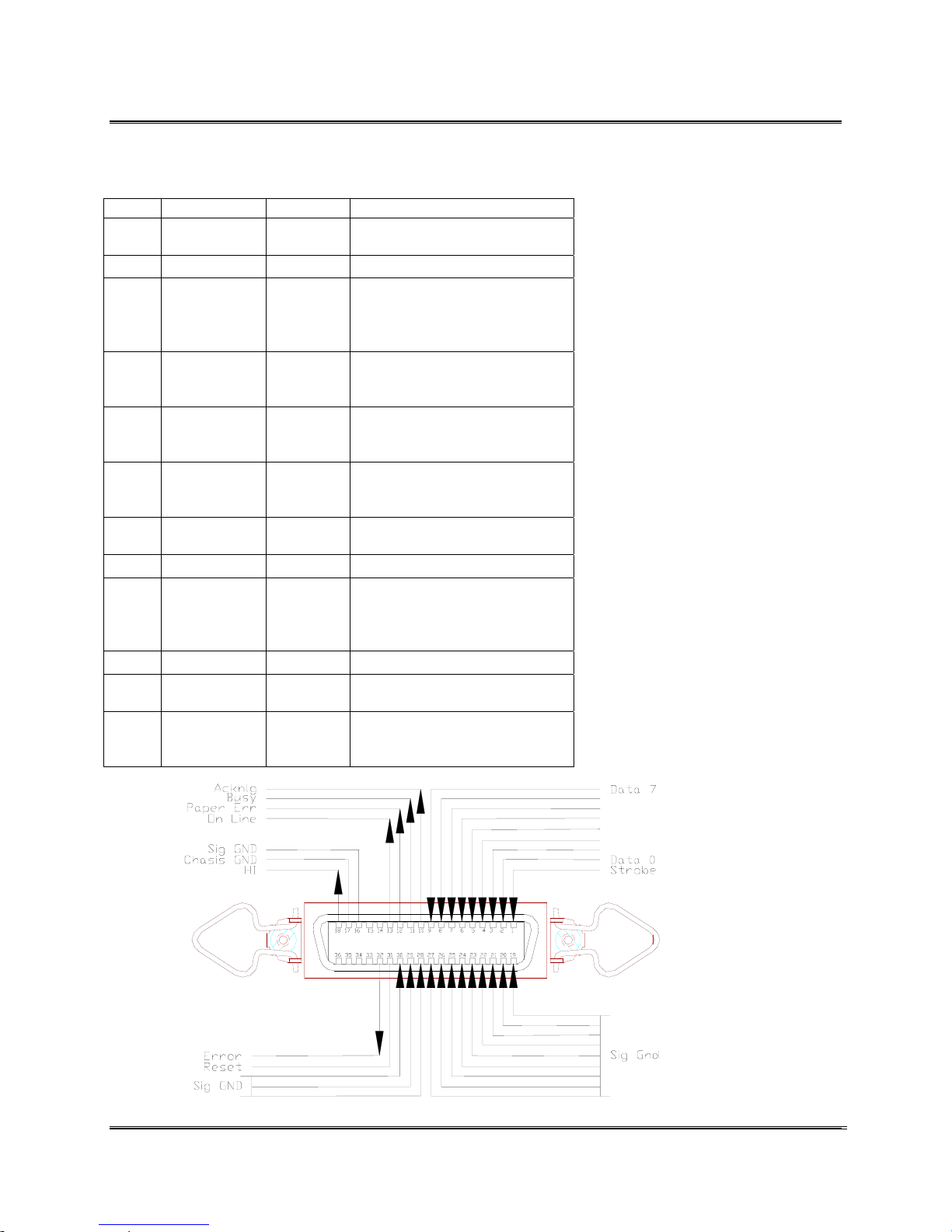
Appendix E Accessory Cable & Parallel Interface
The parallel interface port is a standard 36 pin Amphenol type
with two metal wire retaining clips.
Pin # Signal Direction Description
1 Strobe In A Low pulse causes the printer
to read one byte of data
2-9 Data 0 -Data7 In Data lines. Data 0 is the LSB
10 Acknowledge Out The printer sends a low pulse to
indicate that it has accepted a
byte of data and is ready for
more.
11 Busy Out The printer sends a High to
indicate that it cannot receive
data to data entry, a full buffer.
12 Paper Error Out The printer sends a High logic
level to indicate to the computer
that it is out of paper.
13 On Line Out The printer sends a High logic
level to indicate to the computer
that it is in an On Line status.
16 Sig Gnd These pins are tied to signal
ground
17 Chassis Gnd Chassis Ground
18 HI Out The printer outputs a High logic
level (+5V through a 2.2K ohm
resister) on this pin while it is
turned on.
19-30 Sig Gnd In Signal Interface Ground
31 Reset /Input
Prime
32 Error Out The printer sends a Low logic
The printer may not work when
this line is low.
level to the printer to indicate
that it is in an error state.
Data 6
Data 5
Data 4
Data 3
Data 2
Data 1
Parallel
Communication
(Centronics
Cable)
Revision C 30K USERS MANUAL Section E -
P/N 90-00203-001
1
Page 98
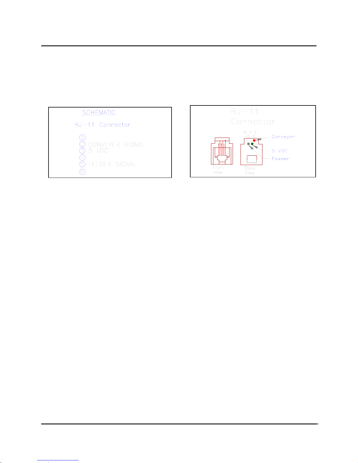
Appendix E Accessory Cable & Parallel Interface
The Accessory Port allows the printer to work in conjunction
with a Conveyor.
Use the Accessory Port to connect the printer to a Bryce Pulse
Box (optional) or to a 5 VDC relay connected to the conveyor
(See Section Connecting to the Conveyor Port for more
information.)
Accessory Port
Revision C 30K USERS MANUAL Section E -
P/N 90-00203-001
2
Page 99

Appendix F Printing with Software
The industrial printer comes with Windows drivers that allow
the use of graphics and a virtually unlimited number of True
Type Fonts. Unlike printing with ASCII text: a non-GUI
operating system that is normally associated with operating
systems like DOS / Unix / Linux, where the printer draws on
the internal fonts, Windows downloads a representation of the
fonts for the printer to make use of.
Driver Information for DOS / Unix / Linux or Windows
3.0, 3.1 & 3.11
Most software packages allow you to select or setup a printer
driver. Use one of the following printer drivers.
Generic Printer
DOS Text Printer
Typewriter
Teletype
TTYCRLF Printer
TTYCR Printer (This requires the Setup Menu
CR = CR + LF option to be turned on)
Printer Software
If none of these choices are available one of the following may
work:
HP Laserjet Series II or any Laserjet II listed
(excluding Postscript)
HP Laserjet 4
Note: When using DOS set the MODE COMMAND!!!
Type the MODE command at the DOS prompt or add the
MODE command to the AUTOEXEC.BAT file. The
AUTOEXEC.BAT will load the command when the computer
is first booted up.
Example:
When printing to the parallel port load MODE
LPT1:,,P
When printing to the serial port load MODE
COM1:9600,N,8,1,P
Note: The parameter settings may vary from the
preceding examples. For DOS version 5.0 or later, a
,,B may be substituted for the ,,P)
Revision C 30K USERS MANUAL Section F – 1
P/N 90-00203-001
Page 100

Appendix F Printing with Software
MICROSOFT WINDOWS™ Applications
Software Driver Information
Microsoft Windows 3.xx Software Driver Information
When using Microsoft Windows 3.0, 3.1 or 3.11, select
the Generic / Text printer driver. The Generic / Text
printer driver is the least complicated and
straightforward driver to use with the printer. Generic /
Text printer drivers only print text and cannot support
the printing of graphics. Some software may list a
Bryce or BOS driver to use with that software package.
Contact the software company for specifics on the
printer driver before using it for it may have been
written specifically for a particular model of Bryce
printer.
Microsoft Windows 95/98, NT 4.0 & XP/2000 Software
Driver Information
Printer Drivers for the aforementioned operating
systems are included with the printer. To take
advantage of the printers’ graphics capabilities and of
True Type Fonts the right printer driver has to be
installed. Once the driver is installed for Windows 95/
98, NT 4.0 or XP/2000 you are ready to print text and
graphics. Use the printer drivers to also set the paper
size, margins, orientation, and to even configure some
of the printers’ control panel settings. The printer
driver will override most control panel settings in the
printer.
Updating the Printer Drivers
Periodically updates of printer drivers are made available on
the World Wide Web. To obtain the most recent drivers or
additional drivers go to
http://www.BryceUSA.com.
Revision C 30K USERS MANUAL Section F – 2
P/N 90-00203-001
 Loading...