

Page 1
PH4Z
SINGLE--PACKAGED HEAT PUMP SYSTEM
WITH PURONr (R--410A) REFRIGERANT
SINGLE PHASE
2 TO 5 NOMINAL TONS (SIZES 024--060)
Product Data
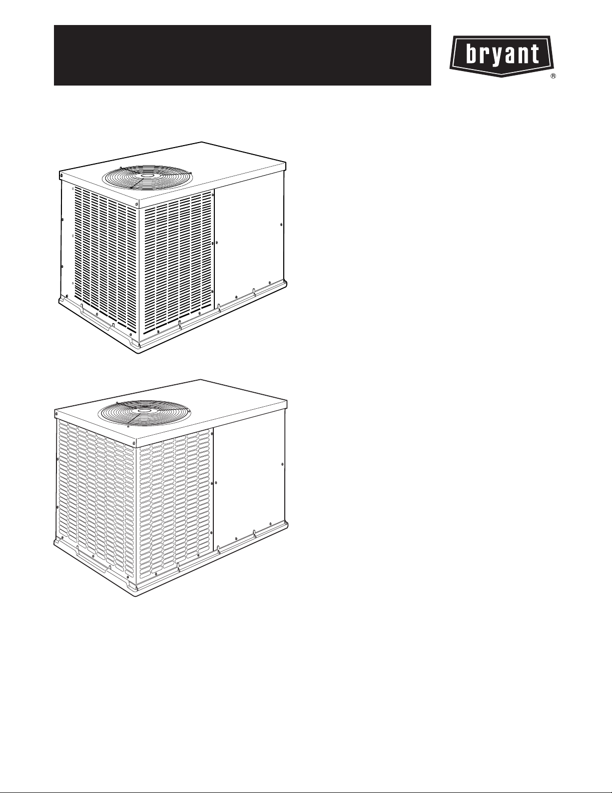
A10165
024--048 Size
A150067
060 Size
Fig. 1 -- Unit PH4Z
Single--Packaged Heat Pump Units with:
S Easy installation design
S Corrosion--proof unit base
S Class leading sound ratings
S Sloped drain for improved indoor air quality
S Scroll compressors
S Front and side service access
S Louvered panel coil protection
FEATURES/BENEFITS
This unit is a packaged heat pump for manufactured housing,
residential, and light commercial applications. Factory assembled
packageis a compact, horizontal supply and return unit, combining
easy installation and maintenance with efficient performance.
EASY TO INSTALL—The units are lightweight, compact single
package units that are easy to handle. Every size unit has an
identical 32 by 51--in. (813 by 1295 mm) footprint to make job
site planning simple. The efficient design uses less sheet metal and
makes the PH4Z units lighter than competitive units. The unit can
be easily positioned on the job site with the hand--holds built into
the unit basepan.
AERODYNAMIC FAN BLADE DESIGN reduces overall sound
by up to 3dBA; low as 73dBA.
SERVICE ACCESS—The units are designed to be serviced from
both front and side. Routine maintenance tasks, such as coil
cleaning, are sped up with the multiple side panels design.
CORROSION PROOF UNIT BASE—The unit features a tough,
high--tech, single--piece composite material unit base with an
integrated drain. The composite material eliminates the potential
problem of rust and premature replacement which are common
with standard metal pans. Each unit base is sloped to eliminate
standing water. This feature minimizes the amount of standing
water inside the unit, which limits mold and mildew growth.
DURABLE STEEL CABINET—The watertight construction
and corrosion--resistant finish will keep it looking like new for
years. A specialized paint treatment process ensures quality
protection against the elements. A compact, low--profile design
utilizes a louvered coil enclosure for maximum protection against
hail damage and vandalism.
SCROLL COMPRESSORS—Each unit comes standard with a
scroll compressor. Each scroll compressor is hermetically sealed
against contamination to help promote longer life and dependable
operation. All scroll compressors have internal high--pressure and
overcurrent protection.
COIL EFFICIENCY—Indoor and outdoor coils are computer
designed for optimum heat transfer and cooling efficiency.
DEFROST SYSTEM—The system provides time/
temperature--based defrost cycles to maintain unit efficiency. This
highly reliable system monitors coil temperature and initiates a
defrost cycle only if it is required. The defrost cycle ends as soon as
defrosting is complete.
ACCESSORY ELECTRIC HEATERS —A variety of accessory
electric heaters are available for these units. These heaters are
comprised of a separate heater module mounted on the blower inlet
and remote mounted controls located in the unit control box.
Single point electrical connections are provided for powering both
the heater and the unit.
START COLLARS—Start collars are provided with each unit to
provide easy connection to the structure ductwork.
DEPENDABLE COMPONENTS—Direct--drive, multi--speed
blower motor is standard on all models.
DIRECT--DRIVE, PSC OUTDOOR--FAN MOTORS are
designed to help reduce energy consumption and provide for
cooling operation down to 40F(4.4C). It’s high efficiency design
ensures high performance with most duct systems.
1
Page 2

REFRIGERANT SYSTEM is designed to provide dependability.
Liquid refrigerant filter driers are used to promote clean,
unrestricted operation. Each unit leaves the factory with a full
MODEL NUMBER NOMENCLATURE
refrigerant charge and is fully run tested. Refrigerant service
connections make checking operating pressure easier.
PH4Z
Typ e of Un i t
P H 4 Z --- S i n g l e Pa c k a g e d
Heat Pump System
Electrical Supply
N --- 208/230---1 ---60
Services
A
Nominal Cooling Capacity
024 --- 2.0 Tons
030 --- 2.5 Tons
036 --- 3.0 Tons
042 --- 3.5 Tons
048 --- 4.0 Tons
060 --- 5.0 Tons
PH4Z
N
A
024
000
Heat Input Size (Btuh)
N/A
A
Low NOx Indicator
A --- S t a n d a r d
N --- L o x N O x ( N / A )
A
TP
Options
TP --- Base unit with tin plated indoor coil hairpins
Only used if ordering an option
Series
TABLE OF CONTENTS
FEATURES/BENEFITS 1.........................................................................................
MODEL NUMBER NOMENCLATURE 2...........................................................................
AHRI CAPACITY RATINGS 3....................................................................................
PHYSICAL DATA 4.............................................................................................
ACCESSORIES 5...............................................................................................
DIMENSIONAL DRAWINGS 6...................................................................................
SELECTION PROCEDURE 9.....................................................................................
PERFORMANCE DATA 11.......................................................................................
TYPICAL WIRING SCHEMATICS 21..............................................................................
CONTROLS 23.................................................................................................
APPLICATION DATA 23.........................................................................................
GUIDE SPECIFICATIONS 24.....................................................................................
PAGE
2
Page 3
AHRI* CAPACITIES
Cooling Capacities and Efficiencies
UNIT SIZE NOMINAL TONS
024 2 800 24,000 11.50 14.50
030 2.5 1000 29,800 11.50 14.50
036 3 1200 36,000 11.50 14.50
042 3.5 1400 42,000 11.50 14.50
048 4 1600 46,500 11.50 14.00
060 5 1700 55,000 11.00 14.00
STANDARD
CFM
Heat Pump Heating Capacities and Efficiencies
NET HEATING
UNIT SIZE
024 23,400 3.7 13,400 2.4 8.0
030 28,600 3.7 15,600 2.4 8.0
036 34,400 3.5 20,200 2.4 8.0
042 40,000 3.5 23,400 2.4 8.0
048 45,000 3.5 26,600 2.3 8.0
060 56,000 3.5 34,000 2.4 8.0
LEGEND
dB---Sound Levels (decibels)
db—Dry Bulb
SEER—Seasonal Energy Efficiency Ratio
wb—Wet Bulb
COP---Coefficient of Performance
* Air Conditioning Heating & Refrigeration Institute
† At "A" conditions--80°F (26.7°C) indoor db/67°F (19.4°C) indoor wb & 95°F (35°C) outdoor db.
** Rated in accordance with U.S. Government DOE Department of Energy) test procedures and/or AHRI Standards 210/240.
Notes:
1. Ratings are net values, reflecting the effects of circulating fan heat.
Ratings are based on:
Cooling Standard: 80°F (26.7°C) db, 67°F wb (19.4°C) indoor entering---air temperature and 95°F db (35°C) outdoor entering---air temperature.
2. Before purchasing this appliance, read important energy cost and efficiency information available from your retailer.
CAPACITY AT 47° F
(8.3° C) (Btuh)
COP @ 47° F
(8.3° C)
NET COOLING CAPA-
CITY AT 95° F (35° C)
(Btuh)
NET HEATING
CAPACITY AT 17° F
(-8.3° C) (Btuh)
EER† SEER**
COP @ 17° F
(-8.3° C)
HSPF**
PH4Z
Use of the AHRI Certified
TM Mark indicates a
manufacturer’s
participation in the
program For verification
of certification for individual
products, go to
www.ahridirectory.org.
A--Weighted Sound Power Level (dBA)
UNIT
SIZE
STANDARD RATING
(dBA)
24 73 54.4 54.9 58.8 67.5 53.7 48.5 39.4
30 75 55.4 63.9 62.8 59.0 54.7 45.5 37.9
36 77 66.2 67.6 72.3 72.6 68.6 62.6 52.5
42 76 64.5 68.1 69.9 69.4 67.0 64.0 58.3
48 75.6 59.9 64.4 64.8 65.0 59.7 55.5 48.9
60 79 67.6 65.7 68.6 70.5 65.3 59.8 50.0
NOTE: Tested in accordance with AHRI Standard 270--- 1995 (not listed in AHRI).
TYPICAL OCTAVE BAND SPECTRUM (dBA without tone adjustment)
125 250 500 1000 2000 4000 8000
3
Page 4
PHYSICAL DATA
UNIT SIZE 024 030 036 042 048 060
NOMINAL CAPACITY (ton) 2 2.5 3 3.5 4 5
SHIPPING WEIGHT (lb)
COMPRESSOR TYPE SCROLL
REFRIGERANT R-410A
REFRIGERANT QUANTITIY (lb)
OUTDOOR METERING DEVICE TXV Piston TXV Piston
ORIFICE ID (in.)
OUTDOOR COIL
ROWS...FINS/in.
FACE AREA (s q. ft)
OUTDOOR FAN
NOMINAL AIRFLOW (cfm)
DIAMETER (in.)
DIAMETER (mm)
MOTOR HP (RPM)
INDOOR METERING DEVICE Piston TXV
ORIFICE ID (in.)
PH4Z
NOMINAL COOLING AIRFLOW (cfm)
HIGH-PRESSURE SWITCH (psig)
*Required filter sizes shown are based on the AHRI (Air Con ditioning, Heating & Refrigeration Institute) rated airflow at a velocity of 300 ft/min (91 m) for thr owaway type or 450 ft/min (137 m) for high capacity type. Recommended filters are 1 - --in. (25 mm) thick.
INDOOR COIL
ROWS...FINS/in.
FACE AREA (s q. ft)
INDOOR BLOWER
NOMINAL SIZE D x L (in.)
MOTOR (HP)
CUTOUT
RESET (AUTO)
LOW-PRESSURE SWITCH (psig)
CUTOUT
RESET (AUTO)
RETURN-AIR FILTERS
THR OWAWAY (in.)
(kg)
QUANTITY (kg)
(mm)
(mm)
(mm)
(mm)
312
142
7.00
3.18
---
---
2...20
9.1
2000
20
508
1/8 (825)
0.059
1.499
3...12
4.3
800
10 x 8
254 x 203
1/3
20x20x1
508x508x25
333
151
7.20
3.27
0.049
1.245
2...20
10.2
2000
20
508
1/8 (825)
0.059
1.499
3...14
4.3
1000
11 x 9
279 x 229
1/3
610x762x25
24x30x1
334
152
6.30
2.86
0.057
1.448
2...20
10.2
2800
20
508
1/4 (1100)
0.067
1.702
3...12
4.9
1200
11 x 9
279 x 229
1/2
650 +/- 15
420 +/- 25
20 +/- 5
45 +/- 10
388
177
9.10
4.13
0.059
1.499
2...20
13.0
3100
20
508
1/4 (1100)
0.076
1.9304
3...14
4.9
1400
11 x 9
279 x 229
1/2
407
185
7.70
3.49
---
---
2...20
15.5
3100
20
508
1/4 (1100)
---
---
3...14
4.9
1600
11 x 9
279 x 229
3/4
24x36x1
610x914x25
475
215
11.5
5.22
0.070
1.778
2...20
15.5
3300
20
508
1/3 (1100)
---
---
3...14
4.9
1700
12 x 11
305 x 279
1
4
Page 5
OPTIONS AND ACCESSORIES
FACTORY
ITEM DESCRIPTION
Coil Options Base unit with tin plated indoor coil hairpins X
Compressor Start Kit
Corporate Thermostats
Crankcase Heater
Electric Heaters Electric Heat Supplement X
Low Ambient Kit
Time Guard II
Refer to Price Pages for available accessories.
Compressor Start Kit assists compressor start- --up by providing
additional starting torque.
Thermostats provide control for the system heating and cooling
functions.
Crankcase Heater provides anti ---floodback protection for low --load cooling applications.
Low Ambient Kit (Motormaster II Control) allows the use of mechanical cooling down to outdoor temperatures as low as 0°F
( ---18° C) when properly installed.
Automatically prevents the compressor from restarting for at least
4 minutes and 45 seconds after shutdown of the compressor. Not
required when a corporate programmable thermostat is applied.
INSTALLED
OPTION
Accessory Electric Heater Usage
CATALOG
ORDERING NO.
NOMINAL
CAPACITY (kW)
CIRCUIT
BREAKER
(Yes/No)
STAGES
024 030 036 042 048 060
CPHEATER125A0* 3.8 / 5.0 No 1
CPHEATER126A0* 3.8 / 5.0 Yes 1
CPHEATER127A0* 5.6 / 7.5 No 2
CPHEATER128A0* 5.6 / 7.5 Yes 2
CPHEATER129A0* 7.5 / 10.0 No 2 NONE
CPHEATER130A0* 7.5 / 10.0 Yes 2
CPHEATER131A0* 11.3 / 15.0 Ye s 2
CPHEATER132A0* 15.0 / 20.0 Ye s 2
Approved combination
USED WITH SIZES
FIELD
INSTALLED
ACCESSORY
X
X
X*
X
X
PH4Z
Multiplication Factors
HEATER kW RATING VOLTAGE DISTRIBUTION MULTIPLICATION FACTOR
200 .69
240
Example: 15.0 kW (at 240v) heater on 208v
=15.0(.75multfactor)
= 11.25 capacity at 208v
208 .75
230 .92
240 1.00
5
Page 6
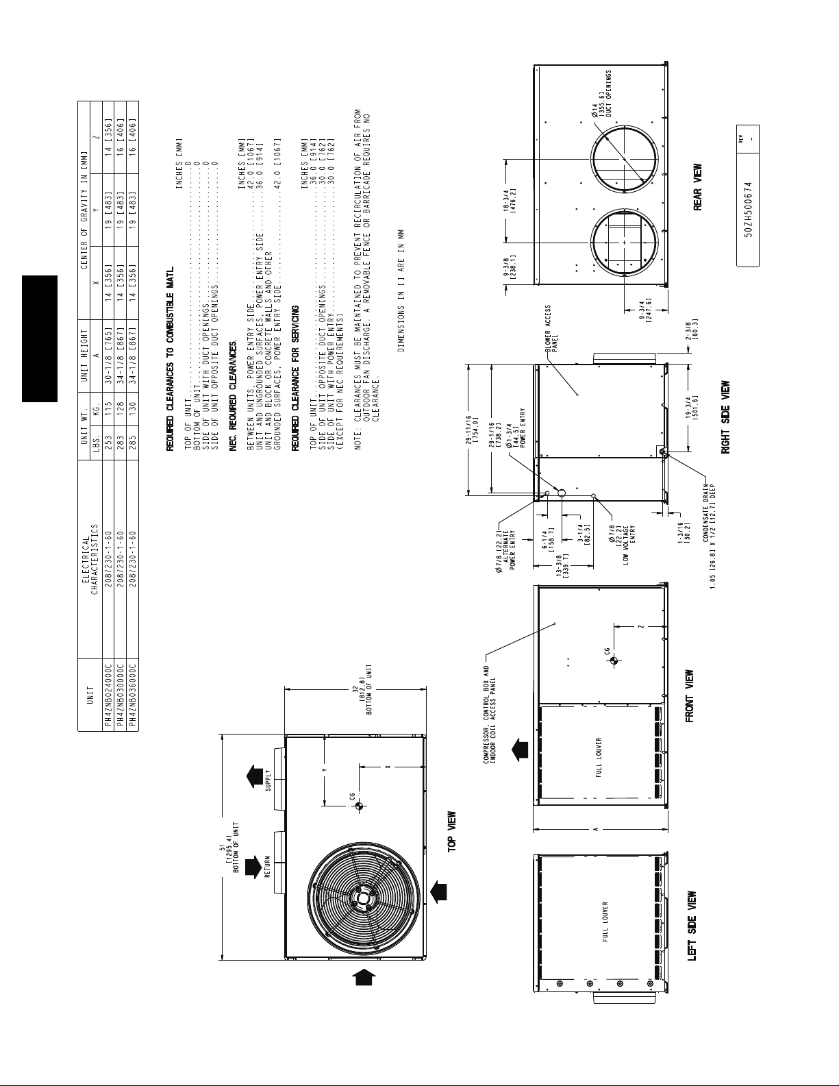
BASE UNIT DIMENSIONS—024--036
PH4Z
A14556
6
Page 7
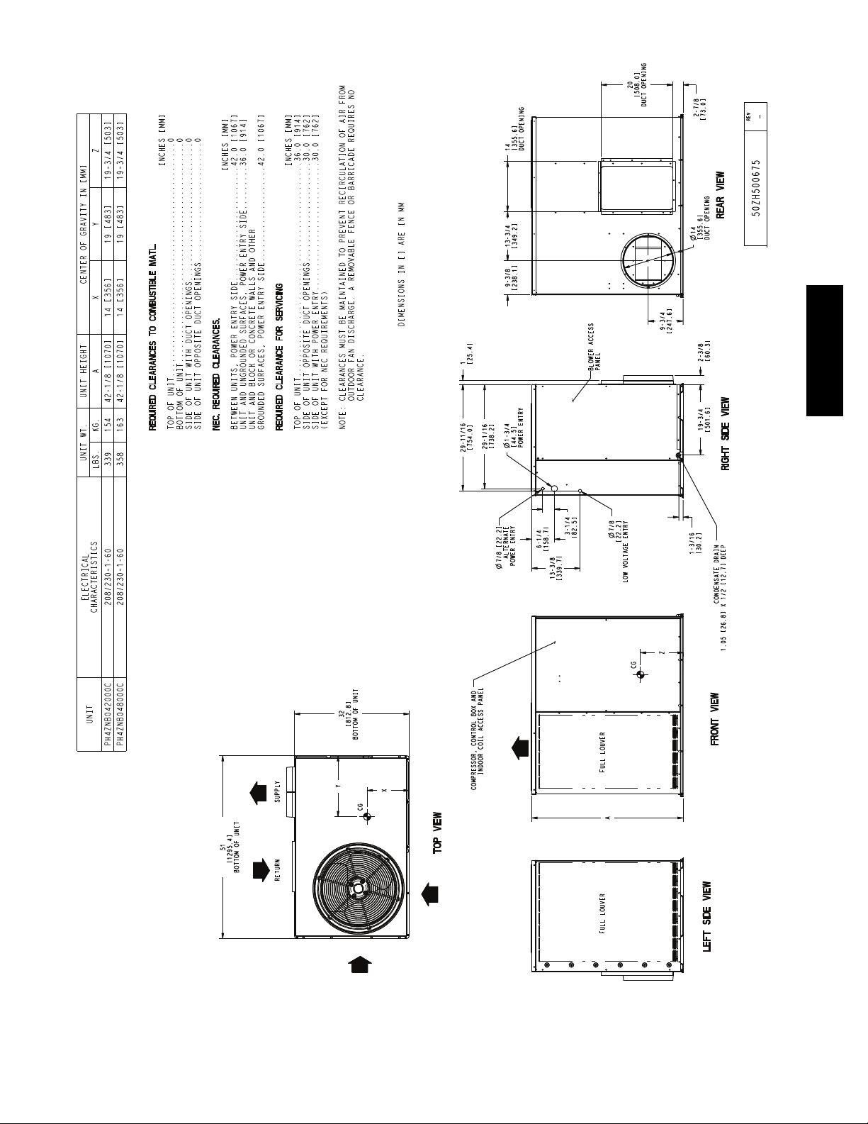
BASE UNIT DIMENSIONS—042--048
PH4Z
A14557
7
Page 8
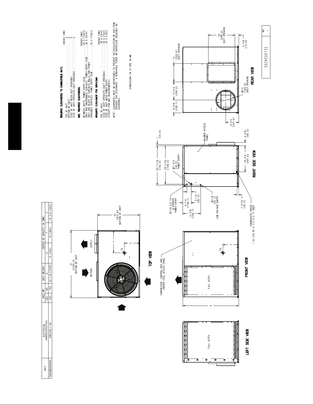
BASE UNIT DIMENSIONS—060
PH4Z
A150072
8
Page 9

SELECTION PROCEDURE
I. DETERMINE COOLING AND HEATING
REQUIREMENTS AT DESIGN CONDITIONS
Given:
Required Cooling Capacity (TC 28,000 Btuh...........
Sensible Heat Capacity (SHC) 20,500 Btuh............
Required Heating Capacity 28,550 Btuh...............
Outdoor Entering--Air Temperature 95F(35C)........
Outdoor--Air Winter Design Temperature 20F(--6.7C)..
Indoor--Air Winter Design Temperature ............70F
(21.1C)
Indoor Entering--Air Temperature . . . . . . . . . . . . . 80F (26.7C)
edb, 67F ewb (19.4C)
Indoor--Air Quantity ........................1000 CFM
ExternalStaticPressure ...................0.20IN.W.C.
ElectricalCharacteristics(V--Ph--Hz)..........230--1--60
edb — entering dry bulb
ewb — entering wet bulb
The required heating capacity is 28,550 Btuh. Therefore, 11,810
Btuh (28,550 -- 16,740) additional electric heat is required.
Determine additional electric heat capacity in kW.
11,810 Btuh
3414 Btuh/kW
3.46 kW of heat required
=
Enter the Accessory Electric Heater Usage table on page 4 for
208/240v. single--phase, 030 unit. The 5--kW heater at 240v most
closely satisfies the heating required. To calculate kW at 230v,
multiply the heater kW by multiplication factor 0.92 found in the
Multiplication Factors table on page 4.
5 kW x 0.92 = 4.6 kW
4.6 x 3414 = 15,704 Btuh
To calculate kW at 208 v, see Multiplication Factors table on page
4.
Total unit heating capacity is 32,444 Btuh (16,740 +15,704).
II. SELECT UNIT BASED ON REQUIRED COOLING
CAPACITY
Enter Cooling Capacities table at condenser entering temperature
of 95F(35C), indoor air entering at 1000 cfm and 67F (19.4C)
ewb (entering wet bulb). The 030 unit will provide a total cooling
capacity of 28,800 Btuh and a sensible heat capacity of 21,600
Btuh.
For indoor--air temperature other than 80F edb (entering dry
bulb), calculate sensible heat capacity correction, as required, using
the formula found in Note 3 following the cooling capacities
tables.
NOTE: Unit ratings are net capacities.
III. SELECT ELECTRIC HEAT
Enter the 030 Heating Capacities table at 1000 CFM. At 70F
(21.1C) return indoor air and 20F(--6.7C) air entering outdoor
coil, the integrated heating capacity is 16,740 Btuh. (Select
integrated heating capacity value since deductions for outdoor--coil
frost and defrosting have already been made. No correction is
required.)
IV. DETERMINE FAN SPEED AND POWER
REQUIREMENTS AT DESIGN CONDITIONS
Before entering the air delivery tables, calculate the total static
pressure required. From the given, the Accessory Electric Heat
Pressure Drop table, and the Filter Pressure Drop table, find:
External static pressure 0.20 IN. W.C.
Filter 0.09 IN. W.C.
Electric heat 0.04
IN. W.C.
Total static pressure 0.33 IN. W.C.
Enter the table for Dry Coil Air Delivery — Horizontal Discharge
at 1000 CFM and 230v high speed. The blower will deliver 1036
CFM @ 0.40 IN W.C. static pressure. This will adequately handle
job requirements.
PH4Z
9
Page 10

kW
PH4Z
23.4
20.5
60
17.6
48
14.6
42
36
11.7
30
8.8
24
5.9
2.9
BASED ON INDOOR ENT. AIR
AT 70 ºF AND AT RATED CFM
0.0
BALANCE POINT WORKSHEET
80
70
60
50
40
30
OUTDOOR TEMPERATURE, ºF
-10 0 10 20 30 40 50 60 70
20
10
0
MBTUH
BUILDING HEAT LOSS, UNIT INTEGRATED HEATING CAPACITY,
A150088
10
Page 11

kW
Sys
kW
Sys
Total
MBtuh
Capacity
kW
Sys
Total
MBtuh
Capacity
Tot a l
MBtuh
Capacity
kW
Sys
Tot a l
MBtuh
Capacity
kW
Sys
Tot a l
PH4Z
MBtuh
kW
Sys
Total
MBtuh
Capacity
Capacity
kW
Sys
Tot a l
MBtuh
Capacity
kW
Sys
Total
MBtuh
Capacity
OUTDOOR COIL ENTERING AIR TEMPERATURES ° F (° C)
CONDENSER ENTERING AIR TEMPERATURES _F(°C)
kW
Sys
Total
MBtuh
Capacity
kW
Sys
Total
75 (24) 85 (29) 95 (35) 105 (41) 115 (46) 125 (52)
MBtuh
Capacity
Total Sens Total Sens Total Sens Total Sens Total Sens Total Sens
-10 (-23) 0 (-18) 10 (-12) 20 (-7) 30 (-1) 40 (4) 50 (10) 60 (16)
kW
Sys
Tot a l
MBtuh
Capacity
kW
Sys
Tot a l
MBtuh
Capacity
kW
Sys
Tot a l
MBtuh
Capacity
kW
Sys
Tot a l
MBtuh
Capacity
Tot a l Integ To t a l Integ To t a l Integ Tot a l Integ To t a l Integ To t a l Integ Tot a l Integ To t a l Integ
PERFORMANCE DATA
EVAPORATOR
COOLING CAPACITY
024
57 (14) 24.13 24.13 1.40 22.67 22.67 1.71 21.20 21.20 2.06 19.18 19.18 2.47 17.23 17.23 2.96 15.34 15.34 3.54
62 (17) 24.96 21.58 1.40 23.28 20.60 1.71 21.59 19.65 2.06 19.26 19.17 2.47 17.27 17.27 2.96 15.37 15.37 3.54
67 (19) 27.16 18.15 1.41 25.39 17.31 1.71 23.57 16.44 2.07 21.73 15.60 2.50 19.32 14.52 2.99 16.69 13.34 3.56
72 (22) 29.39 14.74 1.41 27.59 14.01 1.72 25.69 13.23 2.08 23.72 12.42 2.51 21.74 11.67 3.02 19.42 10.81 3.59
57 (14) 25.10 25.10 1.41 23.59 23.59 1.72 22.07 22.07 2.08 20.33 20.33 2.50 18.25 18.25 2.99 16.19 16.19 3.57
62 (17) 25.55 23.03 1.41 23.84 22.03 1.72 22.15 21.95 2.08 20.37 20.37 2.50 18.29 18.29 2.99 16.22 16.22 3.57
67 (19) 27.67 19.15 1.42 25.86 18.33 1.73 24.00 17.45 2.09 22.11 16.59 2.51 19.85 15.73 3.00 17.17 14.46 3.59
72 (22) 29.86 15.30 1.42 28.03 14.57 1.73 26.11 13.76 2.09 24.08 12.98 2.53 22.06 12.21 3.04 19.80 11.48 3.62
57 (14) 25.89 25.89 1.43 24.34 24.34 1.74 22.76 22.76 2.10 21.17 21.17 2.52 19.11 19.11 3.02 16.95 16.95 3.60
62 (17) 26.06 24.33 1.43 24.36 24.36 1.74 22.78 22.78 2.10 21.19 21.19 2.52 19.15 19.15 3.02 16.99 16.99 3.60
67 (19) 28.05 20.05 1.43 26.22 19.25 1.74 24.32 18.35 2.10 22.40 17.50 2.53 20.23 16.79 3.03 17.60 15.54 3.62
AIR
CFM EWB
63* (17) 25.41 17.66 1.40 23.69 16.80 1.71 21.95 15.92 2.07 19.64 14.77 2.48 17.12 13.57 2.96 14.73 12.42 3.53
700
63* (17) 25.93 18.68 1.42 24.17 17.81 1.72 22.39 16.92 2.08 20.25 15.91 2.50 17.60 14.64 2.98 15.13 13.44 3.55
800
63* (17) 26.33 19.62 1.43 24.53 18.74 1.74 22.72 17.85 2.10 20.71 17.02 2.51 18.05 15.69 3.00 15.48 14.40 3.57
900
72 (22) 30.22 15.79 1.44 28.37 15.07 1.75 26.41 14.26 2.11 24.36 13.48 2.54 22.29 12.72 3.05 20.07 12.05 3.64
700 7.21 6.64 1.43 9.32 8.58 1.49 11.68 10.72 1.55 14.33 13.00 1.61 17.38 15.23 1.68 20.83 20.83 1.76 24.83 24.83 1.84 29.30 29.30 1.93
800 7.25 6.67 1.43 9.36 8.61 1.48 11.71 10.75 1.53 14.37 13.03 1.59 17.43 15.27 1.65 20.89 20.89 1.71 24.92 24.92 1.79 29.46 29.46 1.86
900 7.29 6.70 1.43 9.39 8.64 1.47 11.75 10.78 1.52 14.40 13.06 1.57 17.47 15.31 1.62 20.95 20.95 1.68 25.00 25.00 1.75 29.60 29.60 1.81
700 7.13 6.56 1.50 9.22 8.48 1.56 11.56 10.61 1.62 14.18 12.86 1.69 17.18 15.06 1.76 20.59 20.59 1.84 24.54 24.54 1.93 28.93 28.93 2.02
800 7.16 6.58 1.50 9.25 8.51 1.55 11.58 10.63 1.61 14.20 12.88 1.67 17.22 15.09 1.73 20.64 20.64 1.80 24.62 24.62 1.88 29.07 29.07 1.95
900 7.19 6.61 1.50 9.28 8.53 1.55 11.61 10.65 1.60 14.23 12.91 1.65 17.25 15.12 1.71 20.69 20.69 1.77 24.69 24.69 1.84 29.20 29.20 1.90
700 7.06 6.50 1.57 9.14 8.41 1.64 11.45 10.51 1.71 14.05 12.74 1.78 17.01 14.90 1.85 20.37 20.37 1.94 24.26 24.26 2.03 28.56 28.56 2.12
800 7.09 6.52 1.57 9.16 8.43 1.63 11.47 10.53 1.69 14.06 12.76 1.75 17.03 14.92 1.82 20.41 20.41 1.89 24.32 24.32 1.97 28.69 28.69 2.05
900 7.12 6.55 1.57 9.18 8.45 1.63 11.49 10.54 1.68 14.08 12.77 1.74 17.06 14.95 1.80 20.45 20.45 1.86 24.38 24.38 1.93 28.80 28.80 2.00
65
70
INDOOR AIR
Seepage17forcoolingnotes.
HEATING CAPACITY
024
EDB CFM
(18)
(21)
75
(24)
11
Page 12

PH4Z
kW
Sys
kW
Sys
Total
MBtuh
Capacity
kW
Sys
Total
MBtuh
Capacity
kW
Sys
Total
MBtuh
Capacity
Tot a l
MBtuh
Capacity
kW
Sys
Tot a l
MBtuh
Capacity
kW
Sys
Tot a l
MBtuh
Capacity
kW
Sys
Tot a l
MBtuh
Capacity
kW
Sys
Total
MBtuh
Capacity
OUTDOOR COIL ENTERING AIR TEMPERATURES ° F (° C)
CONDENSER ENTERING AIR TEMPERATURES _F(°C)
kW
Sys
Total
MBtuh
Capacity
kW
Sys
Total
75 (24) 85 (29) 95 (35) 105 (41) 115 (46) 125 (52)
MBtuh
Capacity
kW
Sys
Tot a l
MBtuh
Capacity
kW
Sys
Tot a l
MBtuh
Capacity
kW
Sys
Tot a l
MBtuh
Capacity
kW
Sys
Tot a l
Total Sens Total Sens Total Sens Total Sens Total Sens Total Sens
-10 (-23) 0 (-18) 10 (-12) 20 (-7) 30 (-1) 40 (4) 50 (10) 60 (16)
MBtuh
Capacity
Tot a l Integ To t a l Integ To t a l Integ To t a l Integ To t a l Integ To t a l Integ Tot a l Integ Tot a l Integ
875 7.47 6.87 1.56 10.12 9.31 1.65 13.30 12.21 1.75 16.77 15.21 1.86 20.50 17.96 1.97 24.97 24.97 2.10 30.32 30.32 2.25 36.79 36.79 2.43
875 7.19 6.61 1.64 9.84 9.05 1.73 12.91 11.85 1.83 16.57 15.03 1.96 20.24 17.73 2.07 24.62 24.62 2.20 29.87 29.87 2.35 36.22 36.22 2.53
1000 7.58 6.97 1.57 10.25 9.43 1.65 13.66 12.54 1.76 16.93 15.35 1.85 20.71 18.15 1.95 25.24 25.24 2.07 30.70 30.70 2.21 37.28 37.28 2.38
1125 7.67 7.06 1.57 10.37 9.54 1.65 13.77 12.64 1.75 17.06 15.47 1.84 20.88 18.30 1.94 25.47 25.47 2.05 30.98 30.98 2.18 37.61 37.61 2.36
875 6.90 6.35 1.71 9.54 8.78 1.81 12.58 11.55 1.92 16.37 14.85 2.05 20.00 17.53 2.17 24.29 24.29 2.30 29.43 29.43 2.46 35.66 35.66 2.65
1000 7.30 6.72 1.64 9.97 9.18 1.73 13.08 12.01 1.83 16.72 15.16 1.94 20.45 17.91 2.05 24.89 24.89 2.17 30.24 30.24 2.31 36.69 36.69 2.48
1125 7.40 6.81 1.65 10.09 9.29 1.73 13.24 12.16 1.82 16.86 15.29 1.93 20.61 18.06 2.03 25.11 25.11 2.15 30.52 30.52 2.28 37.03 37.03 2.46
1000 7.01 6.45 1.72 9.68 8.91 1.81 12.76 11.71 1.91 16.53 14.99 2.03 20.19 17.69 2.14 24.54 24.54 2.27 29.78 29.78 2.41 36.12 36.12 2.59
1125 7.11 6.55 1.72 9.80 9.02 1.81 12.90 11.84 1.91 16.65 15.10 2.03 20.34 17.83 2.13 24.76 24.76 2.25 30.07 30.07 2.39 36.45 36.45 2.56
57 (14) 29.24 29.24 1.83 27.70 27.70 2.15 26.11 26.11 2.52 24.49 24.49 2.96 22.75 22.75 3.50 20.93 20.93 4.14
62 (17) 30.19 27.55 1.83 28.33 26.42 2.15 26.44 25.27 2.52 24.56 24.41 2.96 22.80 22.80 3.50 20.97 20.97 4.14
63* (17) 30.79 22.41 1.84 28.86 21.37 2.16 26.91 20.34 2.53 24.89 19.29 2.97 22.79 18.22 3.50 20.56 17.11 4.12
67 (19) 33.31 23.34 1.87 31.27 22.30 2.18 29.18 21.25 2.56 27.03 20.20 3.00 24.77 19.12 3.54 22.46 18.03 4.18
72 (22) 36.86 19.05 1.91 34.65 18.09 2.23 32.38 17.13 2.61 30.03 16.15 3.06 27.59 15.16 3.61 25.07 14.15 4.25
57 (14) 30.61 30.61 1.86 28.97 28.97 2.18 27.29 27.29 2.56 25.55 25.55 3.01 23.72 23.72 3.55 21.82 21.82 4.19
62 (17) 31.02 29.70 1.86 29.13 28.47 2.18 27.33 27.33 2.56 25.59 25.59 3.01 23.75 23.75 3.55 21.84 21.84 4.19
63* (17) 31.52 23.91 1.87 29.53 22.85 2.19 27.49 21.77 2.56 25.40 20.69 3.00 23.23 19.57 3.54 20.97 18.43 4.16
67 (19) 34.09 24.95 1.90 31.97 23.88 2.21 29.80 22.80 2.59 27.56 21.70 3.04 25.24 20.58 3.58 22.85 19.44 4.22
72 (22) 37.71 20.07 1.94 35.41 19.09 2.26 33.04 18.10 2.65 30.61 17.10 3.10 28.09 16.07 3.65 25.47 15.04 4.30
57 (14) 31.77 31.77 1.89 30.04 30.04 2.22 28.28 28.28 2.60 26.44 26.44 3.05 24.52 24.52 3.59 22.52 22.52 4.24
62 (17) 31.81 31.81 1.90 30.08 30.08 2.22 28.32 28.32 2.60 26.48 26.48 3.05 24.55 24.55 3.60 22.55 22.55 4.24
63* (17) 32.11 25.37 1.90 30.05 24.27 2.21 27.96 23.16 2.59 25.81 22.03 3.04 23.58 20.87 3.57 21.30 19.67 4.21
67(19) 34.70 26.52 1.93 32.52 25.41 2.25 30.28 24.29 2.62 27.99 23.15 3.08 25.60 21.98 3.62 23.16 20.79 4.26
72 (22) 38.37 21.05 1.97 35.99 20.05 2.30 33.56 19.03 2.68 31.06 18.00 3.14 28.45 16.95 3.69 25.78 15.89 4.34
AIR
PERFORMANCE DATA (CONT)
COOLING CAPACITY
EVAPORATOR
030
CFM EWB
875
1000
1125
65
70
INDOOR AIR
Seepage17forcoolingnotes.
HEATING CAPACITY
030
EDB CFM
75
12
Page 13

kW
Sys
kW
Sys
To t a l
MBtuh
Capacity
kW
Sys
To t a l
MBtuh
Capacity
Tot a l
MBtuh
Capacity
kW
Sys
Tot a l
MBtuh
Capacity
kW
Sys
Tot a l
PH4Z
MBtuh
kW
Sys
To t a l
MBtuh
Capacity
Capacity
kW
Sys
Tot a l
MBtuh
Capacity
kW
Sys
To t a l
MBtuh
Capacity
OUTDOOR COIL ENTERING AIR TEMPERATURES _F(°C)
CONDENSER ENTERING AIR TEMPERATURES ° F (° C)
kW
Sys
To t a l
MBtuh
Capacity
kW
Sys
To t a l
75 (24) 85 (29) 95 (35) 105 (41) 115 (46) 125 (52)
MBtuh
Capacity
To t a l Sens To t a l Sens To t a l Sens To t a l Sens To t a l Sens To t a l Sens
57 (14) 35.93 35.93 2.36 33.75 33.75 2.70 31.52 31.52 3.08 29.19 29.19 3.52 26.69 26.69 4.03 23.44 23.44 4.55
62 (17) 37.16 32.72 2.36 34.64 31.84 2.70 32.05 30.86 3.08 29.38 29.75 3.52 26.74 26.74 4.03 23.49 23.49 4.55
63* (17) 37.80 26.59 2.36 35.24 25.75 2.70 32.57 24.84 3.08 29.78 23.85 3.52 26.72 22.69 4.03 22.54 20.97 4.53
67 (19) 40.63 27.40 2.36 38.07 26.70 2.70 35.38 25.86 3.09 32.52 24.93 3.54 29.45 23.92 4.05 25.85 22.65 4.64
72 (22) 43.93 21.95 2.37 41.38 21.32 2.72 38.64 20.59 3.12 35.74 19.79 3.57 32.68 18.87 4.08 29.43 17.90 4.66
57 (14) 37.48 37.48 2.39 35.25 35.25 2.73 32.94 32.94 3.12 30.53 30.53 3.56 27.93 27.93 4.08 24.77 24.77 4.64
62 (17) 38.06 35.03 2.39 35.55 34.11 2.73 33.04 32.82 3.12 30.58 30.58 3.56 27.97 27.97 4.08 24.83 24.83 4.64
63* (17) 38.56 28.13 2.39 35.95 27.33 2.73 33.26 26.45 3.12 30.41 25.47 3.56 27.26 24.30 4.08 23.13 22.62 4.58
67 (19) 41.32 28.90 2.39 38.73 28.26 2.74 36.00 27.47 3.13 33.12 26.57 3.58 30.03 25.59 4.09 26.44 24.43 4.67
72 (22) 44.53 22.75 2.41 41.96 22.17 2.76 39.19 21.46 3.16 36.22 20.68 3.61 33.12 19.74 4.12 29.83 18.82 4.70
57 (14) 38.67 38.67 2.42 36.40 36.40 2.76 34.04 34.04 3.15 31.58 31.58 3.60 28.94 28.94 4.12 25.94 25.94 4.71
62 (17) 38.83 36.99 2.42 36.44 36.44 2.76 34.09 34.09 3.15 31.62 31.62 3.60 28.98 28.98 4.12 25.98 25.98 4.71
63* (17) 39.12 29.53 2.42 36.50 28.79 2.77 33.77 27.94 3.16 30.89 26.97 3.60 27.73 25.85 4.11 23.68 24.16 4.64
67(19) 41.83 30.27 2.43 39.21 29.67 2.77 36.45 28.95 3.17 33.55 28.08 3.62 30.48 27.11 4.13 26.96 26.05 4.71
72 (22) 44.95 23.44 2.44 42.38 22.92 2.80 39.58 22.24 3.20 36.58 21.46 3.65 33.42 20.55 4.16 30.10 19.65 4.75
AIR
-10 (-23) 0 (-18) 10 (-12) 20 (-7) 30 (-1) 40 (4) 50 (10) 60 (16)
kW
Sys
Tot a l
MBtuh
Capacity
kW
Sys
Tot a l
MBtuh
Capacity
kW
Sys
Tot a l
MBtuh
Capacity
kW
Sys
Tot a l
MBtuh
Capacity
Tot a l Integ Tot a l Integ Tot a l Integ Tot a l Integ To t a l Integ Tot a l Integ Tot a l Integ To t a l Integ
1050 10.63 9.78 2.08 13.98 12.86 2.18 17.60 16.15 2.29 21.69 19.67 2.41 26.19 22.94 2.56 30.74 30.74 2.70 36.06 36.06 2.85 41.91 41.91 3.00
1200 10.83 9.96 2.09 14.19 13.05 2.19 17.87 16.40 2.30 22.40 20.31 2.42 26.47 23.19 2.54 31.10 31.10 2.66 36.49 36.49 2.79 42.00 42.00 2.93
1350 11.01 10.13 2.11 14.39 13.24 2.21 18.09 16.61 2.31 22.61 20.51 2.42 26.70 23.40 2.53 31.39 31.39 2.65 36.68 36.68 2.76 41.92 41.92 2.89
1050 10.08 9.27 2.15 13.46 12.38 2.26 17.08 15.67 2.38 21.12 19.15 2.51 25.84 22.64 2.67 30.33 30.33 2.82 35.56 35.56 2.99 41.41 41.41 3.14
1200 10.27 9.45 2.17 13.66 12.57 2.27 17.36 15.94 2.38 21.43 19.44 2.50 26.11 22.88 2.65 30.67 30.67 2.78 36.02 36.02 2.92 41.55 41.55 3.07
1350 10.45 9.61 2.19 13.86 12.75 2.29 17.59 16.14 2.39 21.70 19.68 2.50 26.35 23.09 2.64 30.96 30.96 2.77 36.27 36.27 2.89 41.52 41.52 3.02
1050 9.51 8.75 2.24 12.91 11.88 2.35 16.55 15.19 2.48 20.59 18.68 2.61 25.51 22.35 2.79 29.92 29.92 2.95 35.06 35.06 3.13 40.90 40.90 3.29
1200 9.70 8.92 2.26 13.14 12.09 2.37 16.82 15.44 2.48 20.89 18.95 2.60 25.78 22.59 2.76 30.26 30.26 2.91 35.52 35.52 3.06 41.07 41.07 3.21
1350 9.86 9.07 2.28 13.33 12.27 2.38 17.04 15.64 2.49 21.15 19.18 2.61 26.00 22.78 2.75 30.54 30.54 2.89 35.82 35.82 3.02 41.08 41.08 3.16
PERFORMANCE DATA (CONT)
COOLING CAPACITY
036
EVAPORATOR
65
70
CFM EWB
1050
1200
1350
Seepage17forcoolingnotes.
HEATING CAPACITY
INDOOR AIR
036
(18)
EDB CFM
(21)
75
(24)
13
Page 14

PH4Z
kW
Sys
kW
Sys
To t a l
MBtuh
Capacity
kW
Sys
To t a l
MBtuh
Capacity
kW
Sys
To t a l
MBtuh
Capacity
Tot a l
MBtuh
Capacity
kW
Sys
Tot a l
MBtuh
Capacity
kW
Sys
Tot a l
MBtuh
Capacity
kW
Sys
Tot a l
MBtuh
Capacity
kW
Sys
To t a l
kW
Sys
Tot a l
MBtuh
Capacity
MBtuh
Capacity
OUTDOOR COIL ENTERING AIR TEMPERATURES _F(°C)
CONDENSER ENTERING AIR TEMPERATURES ° F (° C)
kW
Sys
Tot a l
MBtuh
Capacity
kW
Sys
Tot a l
MBtuh
Capacity
kW
Sys
Tot a l
75 (24) 85 (29) 95 (35) 105 (41) 115 (46) 125 (52)
kW
Sys
To t a l
MBtuh
Capacity
kW
Sys
To t a l
MBtuh
Capacity
To t a l Sens To t a l Sens To t a l Sens To t a l Sens To t a l Sens To t a l Sens
-10 (-23) 0 (-18) 10 (-12) 20 (-7) 30 (-1) 40 (4) 50 (10) 60 (16)
MBtuh
Capacity
Tot a l Integ To t a l Integ To t a l Integ Tot a l Integ To t a l Integ To t a l Integ To t a l Integ To t a l Integ
57 (14) 42.14 42.14 2.64 39.63 39.63 3.08 37.01 37.01 3.57 33.27 33.27 4.08 29.84 29.84 4.70 26.47 26.47 5.43
62 (17) 43.42 36.94 2.64 40.45 35.78 3.09 37.42 34.53 3.57 33.34 33.34 4.09 29.89 29.89 4.70 26.52 26.52 5.43
67 (19) 47.88 31.26 2.67 44.54 30.15 3.11 41.19 29.02 3.61 37.71 27.83 4.17 32.76 26.04 4.76 28.12 24.34 5.46
72 (22) 53.01 25.46 2.69 49.32 24.38 3.15 45.63 23.29 3.64 41.90 22.17 4.21 38.07 21.00 4.86 33.06 19.39 5.57
57 (14) 44.02 44.02 2.68 41.35 41.35 3.13 38.61 38.61 3.62 35.22 35.22 4.16 31.40 31.40 4.77 27.77 27.77 5.50
62 (17) 44.58 39.74 2.69 41.57 38.42 3.13 38.66 38.66 3.62 35.31 35.31 4.16 31.46 31.46 4.78 27.82 27.82 5.50
67 (19) 48.95 33.40 2.71 45.46 32.26 3.16 42.00 31.10 3.65 38.44 29.89 4.22 33.67 28.17 4.82 28.82 26.35 5.52
72 (22) 54.17 26.80 2.73 50.34 25.70 3.19 46.51 24.59 3.69 42.63 23.44 4.25 38.72 22.26 4.91 34.00 20.78 5.64
57 (14) 45.62 45.62 2.73 42.79 42.79 3.18 39.93 39.93 3.67 36.90 36.90 4.24 32.77 32.77 4.84 28.92 28.92 5.57
62 (17) 45.69 45.69 2.73 42.85 42.85 3.18 39.99 39.99 3.67 36.95 36.95 4.24 32.83 32.83 4.84 28.97 28.97 5.57
67 (19) 49.78 35.47 2.75 46.20 34.29 3.20 42.60 33.09 3.70 38.98 31.84 4.26 34.50 30.21 4.88 29.45 28.21 5.58
63* (17) 46.05 33.91 2.73 42.74 32.75 3.18 39.39 31.55 3.67 35.82 30.22 4.22 30.44 28.04 4.80 26.11 26.11 5.51
72 (22) 55.07 28.09 2.78 51.13 26.97 3.23 47.18 25.83 3.73 43.21 24.67 4.30 39.18 23.46 4.96 34.88 22.14 5.72
1225 12.34 11.36 2.53 15.76 14.50 2.57 19.85 18.22 2.65 25.09 22.75 2.79 29.92 26.22 2.93 35.54 35.54 3.11 42.06 42.06 3.32 49.79 49.79 3.56
1400 12.54 11.54 2.55 15.97 14.70 2.58 20.10 18.45 2.65 25.31 22.95 2.78 30.19 26.45 2.91 35.91 35.91 3.07 42.55 42.55 3.27 50.45 50.45 3.50
1575 12.71 11.69 2.57 16.16 14.87 2.59 20.31 18.64 2.65 25.49 23.12 2.78 30.42 26.65 2.89 36.21 36.21 3.04 42.96 42.96 3.23 50.96 50.96 3.46
1225 11.85 10.90 2.61 15.29 14.07 2.66 19.40 17.80 2.75 24.42 22.15 2.89 29.57 25.91 3.07 35.07 35.07 3.25 41.48 41.48 3.46 49.05 49.05 3.71
1400 12.06 11.09 2.63 15.53 14.29 2.67 19.67 18.05 2.75 25.02 22.69 2.90 29.86 26.16 3.04 35.46 35.46 3.21 41.97 41.97 3.41 49.70 49.70 3.64
1575 12.24 11.26 2.65 15.73 14.47 2.69 19.88 18.25 2.76 25.23 22.88 2.90 30.11 26.38 3.03 35.77 35.77 3.19 42.37 42.37 3.38 50.21 50.21 3.60
1225 11.26 10.36 2.68 14.75 13.57 2.75 18.88 17.33 2.86 23.67 21.47 3.00 29.23 25.61 3.20 34.61 34.61 3.39 40.89 40.89 3.61 48.32 48.32 3.87
1400 11.48 10.56 2.70 14.99 13.80 2.76 19.15 17.58 2.86 24.06 21.82 2.99 29.52 25.86 3.18 34.98 34.98 3.35 41.38 41.38 3.56 48.96 48.96 3.80
1575 11.67 10.74 2.73 15.21 13.99 2.78 19.39 17.80 2.87 24.38 22.11 2.99 29.75 26.06 3.16 35.30 35.30 3.33 41.78 41.78 3.52 49.46 49.46 3.76
AIR
63* (17) 44.22 29.99 2.65 41.17 28.91 3.09 38.00 27.77 3.58 33.40 26.01 4.08 29.10 24.34 4.69 24.87 22.66 5.40
63* (17) 45.24 31.99 2.69 42.05 30.87 3.13 38.79 29.71 3.62 34.39 28.04 4.14 29.80 26.25 4.74 25.51 24.46 5.45
PERFORMANCE DATA (CONT)
COOLING CAPACITY
042
EVAPORATOR
65
70
CFM EWB
1225
1400
1575
Seepage17forcoolingnotes.
HEATING CAPACITY
042
INDOOR AIR
(18)
EDB CFM
(21)
75
(24)
14
Page 15

kW
Sys
kW
Sys
To t a l
MBtuh
Capacity
kW
Sys
To t a l
MBtuh
Capacity
Tot a l
MBtuh
Capacity
kW
Sys
Tot a l
MBtuh
Capacity
kW
Sys
Tot a l
PH4Z
MBtuh
kW
Sys
To t a l
MBtuh
Capacity
Capacity
kW
Sys
Tot a l
MBtuh
Capacity
kW
Sys
To t a l
MBtuh
Capacity
OUTDOOR COIL ENTERING AIR TEMPERATURES _F(°C)
CONDENSER ENTERING AIR TEMPERATURES ° F (° C)
kW
Sys
To t a l
MBtuh
Capacity
kW
Sys
To t a l
75 (24) 85 (29) 95 (35) 105 (41) 115 (46) 125 (52)
MBtuh
Capacity
To t a l Sens To t a l Sens Tot a l Sens To t a l Sens To t a l Sens To t a l Sens
57 (14) 46.42 46.42 3.18 44.08 44.08 3.54 41.54 41.54 3.95 38.75 38.75 4.42 35.66 35.66 4.95 32.25 32.25 5.57
62 (17) 47.91 40.50 3.18 45.08 39.17 3.55 42.09 37.68 3.96 38.91 38.54 4.42 35.70 35.70 4.95 32.29 32.29 5.57
67 (19) 52.27 34.25 3.20 49.14 32.98 3.58 45.78 31.63 3.99 42.12 30.16 4.45 38.13 28.58 4.98 33.83 26.88 5.59
72 (22) 57.10 27.89 3.22 53.65 26.66 3.61 49.95 25.33 4.02 45.93 23.91 4.49 41.59 22.37 5.01 36.91 20.74 5.61
57 (14) 48.26 48.26 3.23 45.74 45.74 3.60 43.02 43.02 4.01 40.04 40.04 4.48 36.76 36.76 5.02 33.12 33.12 5.63
62 (17) 49.02 43.31 3.23 46.11 41.79 3.61 43.09 43.09 4.01 40.09 40.09 4.48 36.80 36.80 5.02 33.15 33.15 5.63
67 (19) 53.29 36.42 3.25 50.03 35.11 3.63 46.50 33.70 4.04 42.68 32.18 4.50 38.56 30.53 5.03 34.15 28.73 5.64
72 (22) 58.19 29.22 3.27 54.58 27.94 3.66 50.71 26.58 4.08 46.53 25.11 4.54 42.02 23.54 5.07 37.21 21.88 5.66
57 (14) 49.79 49.79 3.28 47.12 47.12 3.66 44.25 44.25 4.07 41.10 41.10 4.54 37.62 37.62 5.07 33.80 33.80 5.68
62 (17) 50.03 49.53 3.28 47.17 47.17 3.66 44.30 44.30 4.07 41.15 41.15 4.54 37.65 37.65 5.07 33.83 33.83 5.69
67 (19) 54.07 38.50 3.30 50.68 37.14 3.68 47.02 35.68 4.10 43.10 34.10 4.56 38.87 32.36 5.08 34.38 30.42 5.69
63* (17) 48.68 33.02 3.18 45.78 31.78 3.55 42.67 30.46 3.96 39.29 29.02 4.42 35.60 27.47 4.95 31.60 25.78 5.57
63* (17) 49.67 35.05 3.24 46.64 33.77 3.61 43.39 32.40 4.02 39.87 30.91 4.48 36.05 29.29 5.01 31.96 27.51 5.62
63* (17) 50.44 37.00 3.29 47.28 35.67 3.66 43.93 34.25 4.07 40.31 32.70 4.53 36.41 30.99 5.06 32.23 29.06 5.67
72 (22) 59.02 30.47 3.32 55.27 29.16 3.71 51.27 27.76 4.13 46.95 26.26 4.59 42.32 24.66 5.12 37.39 22.97 5.71
AIR
-10 (-23) 0 (-18) 10 (-12) 20 (-7) 30 (-1) 40 (4) 50 (10) 60 (16)
kW
Sys
Tot a l
MBtuh
Capacity
kW
Sys
Tot a l
MBtuh
Capacity
kW
Sys
Tot a l
MBtuh
Capacity
kW
Sys
Tot a l
MBtuh
Capacity
Tot a l Integ To t a l Integ To t a l Integ Tot al Integ To t a l Integ To t a l Integ Tot a l Integ To t a l Integ
1400 15.18 13.97 2.94 19.00 17.48 3.05 23.31 21.40 3.17 28.19 25.57 3.30 33.88 29.68 3.43 40.24 40.24 3.57 47.39 47.39 3.71 55.53 55.53 3.84
1600 15.30 14.07 2.96 19.11 17.58 3.07 23.43 21.50 3.17 28.32 25.68 3.29 34.03 29.82 3.41 40.45 40.45 3.53 47.70 47.70 3.65 55.99 55.99 3.76
1800 15.41 14.18 2.99 19.23 17.69 3.09 23.55 21.62 3.19 28.46 25.81 3.29 34.20 29.96 3.40 40.66 40.66 3.51 47.98 47.98 3.62 56.39 56.39 3.71
1400 15.09 13.89 3.06 18.87 17.37 3.18 23.15 21.25 3.31 27.98 25.37 3.44 33.59 29.43 3.58 39.86 39.86 3.72 46.87 46.87 3.86 54.85 54.85 4.01
1600 15.19 13.97 3.08 18.96 17.45 3.19 23.24 21.33 3.31 28.08 25.47 3.42 33.73 29.55 3.55 40.06 40.06 3.68 47.18 47.18 3.80 55.31 55.31 3.93
1800 15.29 14.07 3.11 19.07 17.54 3.21 23.35 21.43 3.32 28.20 25.58 3.43 33.87 29.68 3.54 40.25 40.25 3.66 47.45 47.45 3.77 55.70 55.70 3.87
1400 15.08 13.88 3.20 18.82 17.32 3.32 23.04 21.15 3.45 27.80 25.21 3.59 33.33 29.20 3.74 39.48 39.48 3.89 46.35 46.35 4.03 54.16 54.16 4.18
1600 15.16 13.95 3.22 18.89 17.38 3.33 23.12 21.22 3.45 27.89 25.30 3.57 33.45 29.31 3.70 39.67 39.67 3.84 46.65 46.65 3.97 54.61 54.61 4.09
1800 15.25 14.03 3.24 18.98 17.46 3.35 23.21 21.30 3.46 28.00 25.39 3.57 33.58 29.42 3.69 39.85 39.85 3.82 46.91 46.91 3.93 55.01 55.01 4.04
PERFORMANCE DATA (CONT)
COOLING CAPACITY
048
EVAPORATOR
65
70
CFM EWB
1400
1600
1800
Seepage17forcoolingnotes.
HEATING CAPACITY
048
INDOOR AIR
(18)
EDB CFM
(21)
75
(24)
15
Page 16

kW
Sys
kW
Sys
Total
MBtuh
Capacity
kW
Sys
Total
Tot al
MBtuh
Capacity
kW
Sys
Tot al
MBtuh
Capacity
kW
Sys
Tot al
PH4Z
MBtuh
Capacity
kW
Sys
Total
MBtuh
Capacity
kW
Sys
Total
CONDENSER ENTERING AIR TEMPERATURES _F(°C)
MBtuh
Capacity
MBtuh
Capacity
kW
Sys
Tot al
MBtuh
Capacity
kW
Sys
Tot al
MBtuh
Capacity
OUTDOOR COIL ENTERING AIR TEMPERATURES ° F (° C)
kW
Sys
Tot al
MBtuh
Capacity
PERFORMANCE DATA (CONT)
COOLING CAPACITY
Total
75 (24) 85 (29) 95 (35) 105 (41) 115 (46)
Capacity
AIR
EVAPORATOR
060
Sys
MBtuh
CFM EWB
kW
Total Sens Total Sens Total Sens Total Sens Total Sens
57 (14) 53.70 53.70 3.72 50.79 50.79 4.25 47.77 47.77 4.87 44.64 44.64 5.59 41.30 41.30 6.44
62 (17) 56.51 46.21 3.74 53.06 45.28 4.27 49.52 44.21 4.89 45.86 42.96 5.61 42.02 41.46 6.45
63* (17) 57.26 37.98 3.75 53.73 37.03 4.28 50.11 35.97 4.90 46.36 34.78 5.62 42.40 33.40 6.46
1500
67 (19) 61.62 39.46 3.78 57.81 38.52 4.32 53.91 37.46 4.94 49.85 36.25 5.67 45.56 34.86 6.51
72 (22) 67.09 32.70 3.83 62.88 31.73 4.36 58.56 30.66 4.99 54.07 29.45 5.72 49.38 28.08 6.58
57 (14) 55.91 55.91 3.78 52.81 52.81 4.32 49.60 49.60 4.94 46.27 46.27 5.67 42.73 42.73 6.52
62 (17) 57.92 49.22 3.80 54.33 48.19 4.33 50.68 47.03 4.95 46.90 45.63 5.68 42.89 42.89 6.52
63* (17) 58.63 40.05 3.81 54.95 39.07 4.34 51.18 37.98 4.96 47.27 36.73 5.68 43.17 35.30 6.53
1700
67 (19) 63.05 41.68 3.84 59.07 40.70 4.38 55.00 39.60 5.00 50.76 38.34 5.73 46.33 36.90 6.58
72 (22) 68.57 34.07 3.88 64.19 33.07 4.42 59.69 31.95 5.05 55.01 30.69 5.79 50.18 29.28 6.64
57 (14) 57.35 57.35 3.83 54.11 54.11 4.37 50.79 50.79 4.99 47.33 47.33 5.72 43.64 43.64 6.57
62 (17) 58.83 51.31 3.84 55.15 50.22 4.38 51.43 48.93 5.00 47.52 47.52 5.72 43.70 43.70 6.58
67 (19) 63.92 43.28 3.88 59.83 42.27 4.42 55.65 41.14 5.04 51.31 39.85 5.78 46.77 38.38 6.63
63* (17) 59.48 41.54 3.85 55.69 40.53 4.38 51.83 39.41 5.00 47.83 38.14 5.73 43.62 36.67 6.57
1850
16
72 (22) 69.49 35.05 3.93 64.99 34.02 4.46 60.36 32.87 5.10 55.59 31.59 5.83 50.64 30.14 6.69
kW
Sys
Tot al
MBtuh
Capacity
kW
Sys
Tot al
-10 (-23) 0 (-18) 10 (-12) 20 (-7) 30 (-1) 40 (4) 50 (10) 60 (16)
MBtuh
Capacity
Tot al Integ To t a l Integ To t a l Integ To t al Int eg To t a l Integ To t a l Integ Tot al Integ To t a l Integ
1500 20.53 18.88 3.42 24.97 22.98 3.56 30.06 27.59 3.71 35.90 32.56 3.88 42.74 37.45 4.07 50.54 50.54 4.32 59.05 59.05 4.52 68.78 68.78 4.75
1700 20.57 18.92 3.41 24.98 22.99 3.54 30.04 27.57 3.67 35.85 32.51 3.82 42.65 37.37 3.99 50.44 50.44 4.21 58.95 58.95 4.38 68.71 68.71 4.56
1850 20.61 18.96 3.41 25.01 23.01 3.53 30.04 27.57 3.65 35.83 32.50 3.79 42.61 37.33 3.94 50.39 50.39 4.15 58.90 58.90 4.30 68.69 68.69 4.46701500 20.52 18.88 3.60 24.95 22.96 3.76 30.01 27.55 3.92 35.80 32.47 4.10 42.58 37.31 4.30 50.25 50.25 4.55 58.66 58.66 4.77 68.28 68.28 5.02
1700 20.57 18.92 3.59 24.97 22.98 3.73 29.99 27.53 3.87 35.75 32.42 4.03 42.49 37.23 4.21 50.15 50.15 4.43 58.55 58.55 4.61 68.19 68.19 4.81
1850 20.62 18.97 3.59 25.00 23.00 3.72 29.99 27.53 3.85 35.73 32.41 4.00 42.44 37.19 4.16 50.11 50.11 4.37 58.50 58.50 4.53 68.15 68.15 4.69751500 20.49 18.85 3.80 24.92 22.93 3.97 29.95 27.49 4.14 35.71 32.39 4.34 42.41 37.16 4.55 49.95 49.95 4.80 58.27 58.27 5.03 67.78 67.78 5.30
1700 20.55 18.91 3.78 24.94 22.95 3.94 29.94 27.48 4.09 35.66 32.34 4.26 42.32 37.08 4.45 49.85 49.85 4.67 58.15 58.15 4.86 67.67 67.67 5.08
1850 20.60 18.96 3.78 24.97 22.98 3.92 29.94 27.48 4.07 35.64 32.32 4.22 42.28 37.05 4.39 49.80 49.80 4.60 58.09 58.09 4.77 67.63 67.63 4.95
Seepage17forcoolingnotes.
HEATING CAPACITY
060
INDOOR AIR
EDB CFM
65
Page 17

PH4Z
ewb --
h
4.5xCFM
total capacity (Btuh)
lwb =
h
PERFORMANCE DATA (CONT)
LEGEND
lwb)
(Btuh)
1.10 x CFM
Sensible capacity
--
edb
t
ldb =
BF— Bypass Factor
d b --- D r y Bu l b
edb— Entering Dry ---Bulb
Ewb — Entering Wet---Bulb
kW — Total Unit Power Input
ldb— Leaving Dry ---Bulb
lwb— Leaving Wet--- Bulb
SHC — Sensible Heat Capacity (1000 Btuh)
TC — Total Capacity (1000 Btuh) (net)
*At 75_F (23.9_C) entering dry bulb (Tennessee Valley Authority [TVA] rating conditions); all other at 80_F (26.75_C) entering dry bulb.
COOLING NOTES:
1. Ratings are net; they account for the effects of the evaporator --- fan motor power and heat.
2. Direct interpolation is permissible. Do not extrapolate.
t
3. The following formulas may be used:
h
ewb = Enthalpy of air entering evaporator coil
Wet--bulb temperature corresponding to enthalpy
air leaving evaporator coil (
h
lwb =
t
Where:
4. The SHC is based on 8 0_F (26.7_C) edb temperature of air entering evaporator coil. Below 80_F (26.7_C) edb, subtract (corr factor x CFM) from SHC.
Above 80_F (26.7_C) edb, add (corr factor x CFM) to SHC.
Correction Factor = 1.10 x (1 --- BF) x (edb --- 80).
17
Page 18

PERFORMANCE DATA (CONT)
Filter Pressure Drop (IN. W.C.)
FILTER SIZE
in. (mm)
20X20X1
(508X508X25)
20X24X1
(508X610x25)
24X30X1
(610X762x25)
24X36X1
(610X914X25)
500 600 700 800 900 1000 1100 1200 1300 1400 1500 1600 1700 1800 1900 2000 2100 2200
0.05 0.07 0.08 0.10 0.12 0.13 0.14 0.15 — — — — — — — — — —
— — — 0.08 0.09 0.10 0.11 0.13 0.14 0.15 0.16 — — — — — — —
— — — 0.04 0.05 0.06 0.07 0.07 0.08 0.09 0.10 — — — — — — —
— — — — — — — 0.06 0.07 0.07 0.08 0.09 0.09 0.10 0.11 0.12 0.13 0.14
Accessory Electric Heat Pressure Drop (IN. W.C.)
HEATER
kW
800 1000 1200 1400 1600 1800 2000 2200
5--20 0.033 0.037 0.042 0.047 0.052 0.060 0.067 0.075
Wet Coil Air Delivery*
(Deduct 10 percent for 208 Volt Operation)
PH4Z
UNIT
SIZE
024
030
036
042
048
060
*Air delivery values are based on operating voltage of 230v, wet coil, without filter or electric heater. Deduct filter and electric heater pressure drops to obtain
static pressure available for ducting.
NOTES:
1. Do not operate the unit at a cooling airflow that is less than 350 cfm for each 12,000 Btuh of rated cooling capacity. Evaporator coil frosting may occuratairflows below this point.
2. Standard Cubic Feet per Minute
SPEED TAP AIR DELIVERY
1 SCFM 933 799 758 707 675 608 549 497 435 394
2 SCFM 1016 921 882 854 809 761 711 668 599 552
3 SCFM 1079 1041 1003 970 944 909 866 810 764 724
1 SCFM 1052 1018 984 943 914 879 833 795 732 678
2 SCFM 1141 1107 1069 1036 1006 974 932 899 856 784
3 SCFM 1246 1213 1181 1144 1108 1078 1043 1015 973 931
1 SCFM 1311 1253 1195 1136 1083 1023 958 895 818 729
2 SCFM 1413 1364 1313 1256 1203 1148 1084 1022 969 882
3 SCFM 1571 1525 1473 1423 1364 1313 1261 1210 1156 1090
1 SCFM 1499 1434 1394 1349 1307 1273 1232 1169 1108 1038
2 SCFM 1568 1532 1497 1459 1407 1381 1346 1304 1252 1185
3 SCFM 1635 1593 1560 1523 1484 1439 1406 1369 1335 1264
1 SCFM 1657 1625 1590 1554 1517 1486 1448 1417 1381 1340
2 SCFM 1707 1673 1644 1614 1586 1549 1515 1479 1449 1407
3 SCFM 1931 1900 1870 1840 1809 1778 1749 1714 1683 1646
1 SCFM 1774 1746 1717 1678 1639 1590 1538 1492 1461 1418
2 SCFM 1857 1820 1784 1752 1720 1671 1625 1579 1532 1509
3 SCFM 2183 2144 2115 2079 2049 2018 1986 1933 1859 1733
2
230 VOLT HORIZONTAL DISCHARGE
0.1 0.2 0.3 0.4 0.5 0.6 0.7 0.8 0.9 1.0
CFM
CFM
EXTERNAL STATIC PRESSURE (IN. W.C.)
18
Page 19

ELECTRICAL DATA
Units
Nominal
V-PH-HZ
Voltage
Range
MIN MAX FLA FLA kW* 208 240 208 230
24 208/230-1-60 197 253 10.3 61.6 0.9 2.8
30 208/230-1-60 197 253 13.5 72.5 0.9 2.8
36 208/230-1-60 197 253 14.7 75.0 1.7 4.1
42 208/230-1-60 197 253 16.3 112.3 1.7 4.1
48 208/230-1-60 197 253 18.3 108.0 1.7 6.0
60 208/230-1-60 197 253 26.2 144.2 1.9 7.6
*kW @ 208/240
** HACR Type Circuit Breaker
LEGEND
F L A --- Fu l l L o a d Am p s
LRA --- Locked Rotor Amps
MCA --- Minimum Circuit Amps
MOCP --- Maximum Overcurrent Protection
RLA --- Rated Load Amps
NOTES:
1. In compliance with NEC (National Electrical Code) requirements for multimotor and combination load equipment (refer to NEC Articles 430 and 440), the
overcurrent protective device for the unit shall be Power Supply fuse or circuit breaker.
2. Minimum wire size is based on 60_Ccopperwire.Ifotherthan60_C wire is used, or if length exceeds wire length in table, determine size from NEC.
*Heater capacity (kW) based on heater voltage of 208v & 240v. If power distribution voltage to unit varies from rated heater voltage, heater kW will va ry accordingly.
Compressor Electrical Heat Power Supply
RLA LRA
OFM IFM Nominal FLA MCA
-/- - - 16.6 16.6 25
3.8/5 18 20.8 39.1 42.6 40/45
5.6/7.2 27 31.3 50.3 55.7 60/60
7.5/10 36.1 41.7 61.7 68.7 70/70
-/- - - 20.6 20.6 30
3.8/5 18 20.8 43.1 46.6 45/50
5.6/7.2 27 31.3 54.3 59.7 60/60
7.5/10 36.1 41.7 65.7 72.7 70/80
-/- - - 24.2 24.2 35
3.8/5 18 20.8 46.7 50.2 50/60
5.6/7.2 27 31.3 57.9 63.3 60/70
7.5/10 36.1 41.7 69.3 76.3 70/80
11.3/15 54.1 62.5 91.8 102.3 100/110
-/- - - 26.1 26.1 40
3.8/5 18 20.8 48.7 52.5 50/60
5.6/7.2 27 31.3 59.9 65.3 60/70
7.5/10 36.1 41.7 71.3 78.3 80/80
11.3/15 54.1 62.5 93.8 104.3 100/110
-/- - - 30.6 30.6 45
3.8/5 18 20.8 53.1 56.6 60/60
5.6/7.2 27 31.3 64.3 69.7 70/70
7.5/10 36.1 41.7 75.7 82.7 80/90
11.3/15 54.1 62.5 98.2 108.7 100/110
15.0/20.0 72.1 83.3 120.7 134 125/150
-/- - - 42.3 42.3 60
3.8/5 18 20.8 64.8 68.3 70/70
5.6/7.2 27 31.3 76.0 81.4 80/90
7.5/10 36.1 41.7 87.4 94.4 90/100
11.3/15 54.1 62.5 109.9 120.4 110/125
15.0/20.0 72.1 83.3 132.4 146.4 150/150
MOCP**
PH4Z
19
Page 20

TYPICAL INSTALLATION
RETURN
AIR
INDOOR
THERMOSTAT
PH4Z
TOP COVER
Power W iring
Control Wiring
Condenser Airflow
Evaporator Airflow
LOW VOLTAGE
ENTRY
POWER
ENTRY
COMPOSITE
RUST-PROOF
BASEPAN
CONDENSATE
DRAIN
CONNECTION
FROM
POWER
SOURCE
DISCONNECT
PER NEC
(UNIT AND
ELECTRIC
HEATER)
A10135
20
Page 21

TYPICAL CONNECTION WIRING SCHEMATIC—208/230--1--60
PH4Z
21
A14563
Page 22

TYPICAL LADDER WIRING SCHEMATIC—208/230--1--60
PH4Z
22
A14564
Page 23

TYPICAL WIRING SCHEMATIC (CONT)
Wires to be removed
PH4Z
Accessory Electric Heater Wiring
CONTROLS
Sequence of operation
When power is supplied to unit, the transformer (TRAN) is
energized.
Cooling Operation — With a call for cooling (O,Y,G), the
reversing valve, contactor, and indoor fan are energized. When the
cooling demand is met, Y and G are de--energized, shutting off the
contactor (compressor, outdoor fan). The indoor fan stops after a
60 second delay.
Heating Operation — With a call for heating (Y,G), the contactor
and indoor fan are energized. When the heating demand is met, Y
and G are de--energized, shutting off the contactor (compressor,
outdoor fan). The indoor fan stops after a 60 second delay.
Continuous Fan — With the continuous indoor fan option
selected on the thermostat, G is continuously energized keeping the
indoor fan running at all times.
Defrost — The defrost control is a time/temperature control which
includes a field--selectable time period between defrost cycles of
30, 60, and 90 minutes. Electronic timer and defrost cycle start
only when contactor is energized and defrost thermostat (DFT) is
closed.
Defrost mode is identical to cooling mode, except outdoor fan
motor stops and a bank of optional electric heat turns on to warm
air supplying the conditioned space.
A14444
APPLICATION DATA
Condensate trap — A 2--in. (51 mm) condensate trap must be field
supplied.
1” (25 mm) MIN
Maximum cooling airflow — To minimize the possibility of
condensate blow--off from the evaporator, airflow through the units
should not exceed 450 CFM/ton.
Minimum cooling airflow — The minimum cooling airflow is
350 cfm/ton.
Minimum cooling operating outdoor air temperature —All
standard units have a minimum ambient operating temperature of
40F(4.4C). With accessory low ambient temperature kit, units
can operate at temperatures down to 0F (--17.8C).
Maximum operating outdoor air temperature —Maximum
outdoor operating air temperature for cooling is 125F (51.7C).
.
TRAP
OUTLET
2” (51 mm) MIN.
23
Page 24

GUIDE SPECIFICATIONS
SMALL PACKAGED PRODUCT AIR--TO--AIR
HEAT PUMP CONSTANT VOLUME APPLICATION
HVAC GUIDE SPECIFICATIONS
SIZE RANGE: 2 TO 5 TONS, NOMINAL (COOLING)
PART I -- GENERAL
SYSTEM DESCRIPTION
Outdoor packaged, electrically controlled, air--to--air heat
pump utilizing a scroll compressor for heating and cooling
duty. Unit shall discharge supply air horizontally as shown on
contract drawings.
QUALITY ASSURANCE
A. Unit shall be rated in accordance with AHRI Standards
210/240, and 270. Designed in accordance with UL
Standard 1995.
B. Unit shall be designed to conform to ASHRAE 15.
C. Unit shall be UL listed as a total package for safety
requirements.
D. Insulation and adhesive shall meet NFPA 90A
PH4Z
requirements for flame spread and smoke generation.
DELIVERY, STORAGE, AND HANDLING
Unit shall be stored and handled per manufacturer’s
recommendations.
PART 2-- PRODUCTS
EQUIPMENT
A. General:
Factory--assembled, single piece, air--to--air heat pump.
Contained within the unit enclosure shall be all factory wiring,
piping, controls, and refrigerant charge (R--410A).
B. Unit Cabinet:
1. Unit cabinet shall be constructed of phosphated,
bonderized, zinc--coated, prepainted steel.
2. Basepan shall be made of a single--piece non--corrosive,
composite material.
3. Indoor fan compartment cabinet surfaces shall be insulated
with a minimum 1/2 in. (12.7 mm) thick, flexible
insulation, coated on the air side, with aluminum foil--faced
insulation.
4. Cabinet panels shall be easily removable for servicing.
5. Unit shall have a factory--installed, sloped, noncorrosive,
condensate drain.
6. Unit insulation conforms to ASHRAE 62P.
C. Fans:
1. Indoor Blower (Indoor Fan):
a. Fan shall be multispeed, direct drive as shown on the
equipment drawings.
b. Fan wheel shall be made from steel, be double--inlet
type. It shall have forward--curved blades with a
corrosion--resistant finish and shall be dynamically
balanced.
2. Outdoor fan shall be of the direct--driven propeller type
with aluminum blades, riveted to corrosion--resistant steel
spiders. It shall be dynamically balanced, and shall
discharge air upwards.
D. Compressor:
Fully--hermetic scroll type with external vibration isolation.
E. Coils:
1. Indoor and outdoor coils shall have aluminum--plate fins
mechanically bonded to seamless copper tubes with all
joints brazed.
2. Tube sheet openings shall be bellied to prevent tube wear.
3. Outdoor coil shall be protected by metal louvered panels.
F. Refrigerant Components:
1. TXV and AccuRater feed system.
2. Service gauge connections on suction and discharge lines.
3. Equipped with liquid line filter drier.
4. Equipped with accumulators on all sizes.
G. Controls and Safeties:
1. Unit Controls:
a. Unit shall be complete with self--contained low voltage
control circuit.
b. Unit shall incorporate an outdoor coil defrost system to
prevent excessive frost accumulation during heating
cycle and shall be controlled as follows:
(1.) Defrost shall be initiated on the basis of time and
coil temperature.
(2.) A 30/60/90--minute timer shall activate defrost
cycle only if coil temperature is low enough to
indicate a heavy frost condition.
(3.) Defrost cycle shall terminate when defrost
thermostat is satisfied or shall have a positive
termination time of 10 minutes.
2. Safeties:
a. High Pressure Switch
b. Loss of Charge Switch
H. Operating Characteristics:
1. Unit shall be capable of starting and running at 125F
(51.7C) ambient outdoor temperature (60 size max ambient is 115F [46.1C]).
2. Compressor with standard controls shall be capable of
operation down to 40F(4.4C) ambient outdoor
temperature in cooling duty.
3. Compressor shall be capable of operation in heating cycle
down to --20F (--28.9C) ambient outdoor--air temperature.
4. Unit shall be capable of simultaneous heating duty and
defrost cycle operation when using electric heaters indicated
in Section L, Special Features.
I. Electrical Requirements:
All unit power wiring shall enter unit cabinet at a single
location.
J. Motors:
1. Compressor motors shall be of the refrigerant--cooled type
with line break thermal and current overload protection.
2. All fan motors shall have permanently lubricated bearings
and inherent automatic--reset thermal overload protection.
3. Outdoor--fan motor shall be totally enclosed.
24
Page 25

GUIDE SPECIFICATIONS (CONT)
K. Grille
1. Louvered Grille:
Louvered grille shall be standard on all units.
L. Special Features Available
1. Coil Options:
Shall include factory--installed optional tin--plated indoor
coil.
2. Thermostat:
To provide for two--stage heating and one--stage cooling in
addition to manual or automatic changeover and indoor fan
control.
3. Low--Ambient Package:
Shall consist of a solid--state control and outdoor coil
temperature sensor for controlling outdoor fan motor
operation, which shall allow unit to operate down to 0F
(--17.8C) outdoor ambient temperature in cooling.
4. Crankcase Heater:
Shall provide anti--floodback protection for low--load
cooling applications.
5. Electric heaters:
a. Electric heater shall be available as a field--installed
option.
b. Heater elements shall be open wire type, adequately
supported and insulated with ceramic bushings.
c. Electric heater packages must provide single point
power connection capability.
6. Compressor Start Kit:
Shall be available to give a boost to the compressor motor
at each start--up.
7. Outdoor Thermostat Kit:
Thermostat allows for staging of electric heaters based on
outdoor air temperature.
PH4Z
25
Page 26

PH4Z
26
Page 27

PH4Z
27
Page 28

PH4Z
E2017 Bryant Heating & Cooling Systems D 7310 W. Morris St. D Indianapolis, IN 46231 Edition Date: 07/17
Manufacturer reserves the right to discontinue, or change at any time, specifications or designs without notice and without incurring obligations.
28
Catalog No. PDSPH4Z ---04
Replaces: PDSPH4Z --- 03
 Loading...