

Page 1
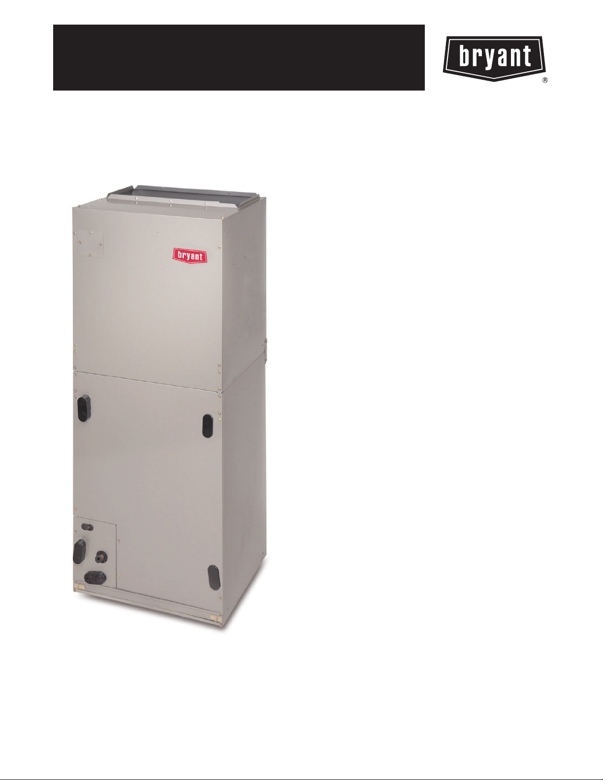
FV4B
PREFERREDt SERIES F AN COIL
SIZED 002 THRU 006
Produc t Data
PREMIUM ENVIRONMENTALLY
SOUND FAN COIL
The FV4B is the premium air handler combining the proven
technology of Bryant fan coils with environmentally sound Purone
refrigerant. The FV4B achieves an operational advantage when the
ECM (Electronically Commutated Motor) is combined with a
Bryant Preferredt heat pump with Purone refrigerant.
With attention to quiet, efficient, and comfortable operation, Bryant
has developed a new benchmark for superior indoor comfort and
control.
Bryant’s heat pump and air conditioning systems now feature
Purone refrigerant (R--410A), the chlorine--free refrigerant that is
the future for the residential heating and cooling industry. The
FV4B using Purone refrigerant maximizes performance for
environmentally sound systems. In addition to environmental
safety, these systems are 30 to 40% more efficient than standard
heating and cooling systems, thereby combining excellence in
efficiency and environmental safety.
The FV4B provides these benefits due to Bryant’s command of
ECM technology. These motors are extremely efficient at all
speeds, and enable the FV4B to operate at the correct speed to
deliver airflow precisely, ensuring proper performance across a
wide range of duct static pressures. This adaptive efficiency also
makes installation quality easier to achieve for today’s demanding
homeowner.
Bryant’s command of ECM technology may be most evident in the
comfort advantages that ECM can deliver. Operation set up steps
on the Easy Selectt Board provide the installing technician with
alternatives to maximize comfort and efficiency. For true indoor
comfort, the homeowner can achieve command of both
temperature and humidity in cooling and heating modes.
Another feature which sets the FV4B apart is the factory--installed
TXV , which enhances efficiency and provides compressor
protecting operation at all recommended conditions. Grooved
copper tubing, louvered aluminum fins, and the large face areas of
the FV4B refrigerant coils also provide superior efficiency, for high
SEER and HSPF performance. Bryant leads the way in condensate
control, a hallmark of these multipoise fan coils. All of these
featured components are protected within a rugged, prepainted
metal cabinet lined with super thick, high density insulation. For
neat, high quality installations the unit exterior features sweat
refrigerant connections for simple leak free performance, and
multiple electrical entry for both high and low voltage service.
For superior technology and unmatched comfort, the
environmentally sound and efficient FV4B can’t be beat.
Page 2

FEATURES
Environmentally Sound Refrigerant Technology
Puronr, chlorine--free non--ozone depleting refrigerant
S
S Thermostatic Expansion Valve (TXV) designed to maximize performance with Puronr refrigerant
Energy Efficient Operation
Electronically Commutating Motor (ECM) operates efficiently at all speeds
S
S Maximizes efficiency of heating and cooling systems
S Ultra low power consumption during fan only operation
Indoor Weather Control
Warm, comfortable heating air temperatures
S
S Unmatched humidity control, especially with Bryant’s Thermidistatt Control
Airflow and Sound Technology
Diffuser air discharge section for high airflow efficiency and quiet, smooth operation
S
S High duct static capability
FV4B
S Unique cabinet design that meets new stringent regulations for air leakage. Meets requirements of a 2% cabinet leakage rate when
tested at 1.0 inches of static pressure
Condensate Control and Disposal Technology
Minimal standing water -- less microbial growth for improved IAQ and reduced condensate line clogging and related condensate
S
leakage
S Condensate fittings relocated away from turbulent airflow patterns at the blower entrance for improved condensate control
performance
S Overflow feature for slope coil units allows condensate to exit the unit without damage to product under clogged primary and
secondary line conditions
S Tested for condensate disposal at conditions much more severe than those required by ARI
S Primary and secondary drain connections to comply with HUD
S All pans constructed of an injection molded glass--filled polycarbonate engineered resin material, with brass drain connections.
S High density, super thick cabinetry insulation with vapor barrier
S Pre--painted galvanized sheet metal cabinet
Heat Transfer Technology
Grooved copper tubing
S
S Lanced sine wave aluminum fins
S Discreet refined counterflow refrigerant circuitry
S Bi--flow hard shut--off TXV metering device
Quality Assisting, Ease of Installation and Service Features
All units multipoise
S
S Provision made for suspending from roof or ceiling joints
S Modular cabinet on 003 thru 006 units
S Sweat connections for leak free service
S Multiple electrical entry for application flexibility (high and low voltage)
S Low voltage terminal strip, to safely hold connections within the cabinet
S Inspection plate on A--coil models for quick coil cleanliness inspection
S Cabinet construction features innovations designed to prevent cabinet sweating
Controls and Electrical Features
Easy Selectt Board to maximize comfort, efficiency, and safe heater airflow operation
S
S Easy plug connection provided for quick installation of accessory heater packages
S 40VA 208/230v transformer
S Replaceable 5--amp blade--type auto fuse protects against transformer secondary short
Filter Features
Factory supplied filter
S
S Cleanable polyester filter media
S Filter “springs” out for easy access -- no tools required
S Newly improved filter rack area -- filter door insulation added for an improved air seal
2
Page 3
MODEL NUMBER NOMENCLATURE
1 2 3 4 5 6 7 --- 9 1 0 --- 1 2
F V 4 B N B 003 000
Product Type Position Series Electrical Cabinet/
F = Fan Coil V = Preferredt
Puronr refrigerant
the environmentally sound refrigerant
4 = Multipoise B N = 208/230v,
1ph---60hz
CERTIFICATION APPLIES ONLY WHEN THE
COMPLETE SYSTEM IS LISTED WITH ARI
Insulation
B= Modular
F=Singlepiece
Capacity Heating
002 = 18 --- 36,000
003 = 24 --- 42,000
005 = 30 --- 48,000
006 = 30 --- 60,000
Size
000 = No Heat
005 = 5 kW
075 = 7.5 kW
008 = 8 kW
010 = 10 kW
011 = 11 kW
015 = 15 kW
ISO 9001:2000
REGISTERED
SPECIFICATIONS
MODEL FV4B 002 003 005 006
COIL
Refrigerant Metering Device Puronr Refrigerant (R---410A)
TXV Size 2Ton 3Ton 4Ton
Rows/Fins Per In. 3 / 14.5
Face Area (Sq Ft) 3.46 5.93 7.42
Configuration A Slope A
BLOWER & MOTOR
Air Discharge Upflow, Downflow, Horizontal
525 / 470
CFM (Nominal Clg/Htg)
700 / 630
875 / 785
1050 / 945
Motor HP (ECM) 1/2 3/4
Filter Cleanable (In.) 21--- 1/2 x 16 ---3/8 21--- 1/2 x 19 ---7/8 21 ---1/2 x 23--- 5/16
CABINET CONFIGURATION OPTIONS
1Piece 1PieceorModular Modular
700 / 630
875 / 785
1050 / 945
1225 / 1100
875 / 785
1050 / 945
1225 / 1100
1400 / 1260
1050 / 945
1225 / 1100
1400 / 1260
1750 / 1575
FV4B
3
Page 4
FV4B
A B C D E H J
In. In. In. In. In. In. In.
UNIT SIZE
FV4BNF 002 42--- 11/16 17---5/8 15--- 3/4 15---5/8 10---3/4 — —
FV4BNF 003 53 ---7/16 21--- 1/8 19---1/4 19---1/8 19--- 3/16 — 19
FV4BNB 003 53---7/16 21 ---1/8 19 --- 1/4 19---1/8 19 ---3/16 28---5/16 19
FV4BNB 005 53---7/16 21 ---1/8 19 --- 1/4 19---1/8 19 ---3/16 28---5/16 —
FV4BNF 005 53 ---7/16 21--- 1/8 19---1/4 19---1/8 19 --- 1/2 — —
FV4BNB 006 59---3/16 24---11/16 22--- 3/4 22---11/16 25---1/4 34---1/16 —
DIMENSIONS
4
Page 5
FV4B
F G COIL C ONFIGURATION SHIPPING WEIGHT
In. In. SLOPE “A” Lb
UNIT SIZE
FV4BNB 003 26---15/16 27 ---1/2 Ye s — 150
FV4BNB 005 26---15/16 27 ---1/2 — Ye s 172
FV4BNB 006 32---15/16 32 ---5/8 — Ye s 207
FV4BNF 002 18 ---9/16 18--- 1/4 — Ye s 135
FV4BNF 003 26 --- 15/16 27---1/2 Ye s — 150
FV4BNF 005 27---1/4 26 ---15/16 — Yes 172
DIMENSIONS
5
Page 6
PERFORMANCE DATA
FV4V ADVANCED FAN COIL AIRFLOW DELIVERY CHART (CFM)
OPERATING MODE—COOLING
UNIT
SIZE
OUTDOOR
UNIT
CAPACITY*
018
002
024
030
036
024
003
030
036
042
030
005
FV4B
006
036
042
048
036
042
048
060
*Consult ARI ratings before matching outdoor unit with FV4B fan coil.
NOTES:
1. The above airflows result with the AC/HP CFM ADJUS T select ju mper set on NOM.
2. Airflow can be adjusted +15% or --- 10% by selecting HI or LO respectively for all modes except fan only.
3. Dry coil at 230 volts and with 10---kW hea ter and filter installed.
4. Airflows shown are at standard air conditions. (0.075 lb/ft
Single--- Speed Application
Nominal
A/C
Cooling
525
700
875
1050
700
875
1050
1225
875
1050
1225
1400
1050
1225
1400
1750
A/C
Cooling
Dehumidity
420
560
700
840
560
700
840
980
700
840
980
1120
840
980
1120
1400
3
High Speed Low Speed
Nominal
A/C
Cooling
—
735
—
1100
735
—
1100
—
—
1100
—
1470
1100
—
1470
1835
at 29.92 in---Hg).
Two--- Speed Application
A/C
Cooling
Dehumidify
—
590
—
880
590
—
880
—
—
880
—
1175
880
—
1175
1470
Nominal
A/C
Cooling
—
440
—
660
440
—
660
—
—
660
—
880
660
—
880
1100
A/C
Cooling
Dehumidify
—
350
—
530
415
—
530
—
—
530
—
705
530
—
705
880
FAN ONLY
Lo/Med/Hi
350/350/525
350/440/700
440/550/875
525/660/1050
415/440/700
440/550/875
525/660/1050
610/770/1225
440/550/875
525/660/1050
610/770/1225
700/880/1400
525/660/1050
610/770/1225
700/880/1400
875/1100/1750
FV4B ADVANCED FAN COIL AIRFLOW DELVERY CHART (CFM)
OPERATING MODE—HEAT PUMP ONLY HEATING
UNIT
SIZE
002
003
005
006
*Consult ARI ratings before matching outdoor unit with FV4B fan coil.
NOTES:
1. The above airflows result with the AC/HP CFM ADJUS T select ju mper set on NOM.
2. Airflow can be adjusted +15% or --- 10% by selecting HI or LO respectively for all modes except fan only.
3. Dry coil at 230 volts and with 10---kW hea ter and filter installed.
4. Airflows shown are at standard air conditions. (0.075 lb/ft
OUTDOOR
UNIT
CAPACITY*
018
024
030
036
024
030
036
042
030
036
042
048
036
042
048
060
Single--- Speed Application
Heat Pump
Comfort
470
630
785
945
630
785
945
1100
785
945
1100
1260
945
1100
1260
1575
Heat Pump
Efficiency
525
700
875
1050
700
875
1050
1225
875
1050
1225
1400
1050
1225
1400
1750
3
High Speed Low Speed
Heat Pump
Comfort
—
660
—
990
660
—
990
—
—
990
—
1320
990
—
1325
1655
at 29.92 in---Hg).
Two--- Speed Application
Heat Pump
Heat Pump
Efficiency
—
735
—
1100
735
—
1100
—
—
1100
—
1470
1100
—
1470
1835
Comfort
—
395
—
595
415
—
595
—
—
595
—
795
595
—
795
990
Heat Pump
Efficiency
—
440
—
660
440
—
660
—
—
660
—
880
660
—
880
1100
FAN ONLY
Lo/Med/Hi
350/350/470
350/395/630
440/495/785
525/595/945
415/415/630
440/495/785
525/595/945
610/695/1100
440/495/785
525/595/945
610/695/1100
700/795/1260
540/595/945
610/695/1100
700/795/1260
875/990/1575
6
Page 7

PERFORMANCE DATA (cont)
AIRFLOW DELIVERY CHART (CFM) — ELECTRIC HEATING MODES
UNIT SIZE
OUTDOOR UNIT
CAPACITY BTUH
18,000
002
003
005
006
Where dash (—) appears indicates airflow not recommended for heater/system size.
NOTE: LO, NOM and HI refer to the AC/HP CFM ADJUST selection.
24,000
30,000
36,000
24,000
30,000
36,000
42,000
30,000
36,000
42,000
48,000
36,000
42,000
48,000
60,000
Lo Nom Hi Lo Nom Hi Lo Nom Hi Lo Nom Hi
625
650
815
980
675
815
980
1140
975
980
1140
1305
1100
1140
1305
1630
0–5 0–10 0–15 0–20
625
725
905
1085
725
905
1085
1270
975
1085
1270
1450
1100
1270
1450
1810
625
835
1040
1250
835
1040
1250
1460
1040
1250
1460
1665
1250
1460
1665
2085
675
980
875
875
980
1140
1100
1100
1140
1305
1350
1350
1350
1630
ELECTRIC HEATER kW RANGE
—
—
675
725
905
1085
875
905
1085
1270
1100
1100
1270
1450
1350
1350
1450
1810
675
835
1040
1250
875
1040
1250
1460
1100
1250
1460
1665
1350
1460
1665
2085
MINIMUM CFM FOR ELECTRIC HEATER APPLICATION
UNIT SIZE
002
003
005
006
NOTES:
1. Heater Only — Air Conditioner with electric heater application.
2. Th ese airflows are minimum acceptable airflows as UL listed.
3. Actual airflow delivered will be per the airflow delivery chart for Electric Heating Modes.
HEAT PUMP
UNIT SIZE
Heater O n ly
018
024
030
036
Heater O n ly
024
030
036
042
Heater O n ly
030
036
042
048
Heater O n ly
036
042
048
060
5 8, 9, 10 15 18, 20 24, 30
625
625
650
800
970
675
675
800
975
1125
675
800
975
1125
1305
1050
1100
1125
1300
1625
625
625
725
875
970
700
875
875
975
1125
700
875
975
1125
1305
1050
1100
1125
1300
1625
—
875
900
980
1100
1100
1140
1250
1250
1305
1525
1525
1630
Heater Size kW
1085
—
1100
1100
1270
—
1250
1270
1450
—
1525
1525
1810
CFM
725
—
875
875
970
1050
—
1100
1100
1125
1050
1100
1100
1125
1305
1050
1350
1350
1350
1625
—
875
900
—
—
—
—
875
1040
1250
—
1100
1250
1460
—
1250
1460
1665
—
1525
1665
2085
875
—
—
1040
1040
1050
—
—
1225
1225
1050
—
1225
1225
1305
1050
1350
1350
1465
1750
—
—
1100
1100
—
—
1225
1225
—
—
—
1500
—
—
1750
1750
—
—
1100
1100
—
—
1225
1270
—
—
—
1500
—
—
1750
1810
—
—
—
—
—
—
—
—
—
—
1400
—
—
—
1400
1750
—
—
1750
1750
—
—
1100
1250
—
—
1250
1460
—
—
—
1665
—
—
1750
2085
FV4B
7
Page 8

PERFORMANCE DATA (cont)
0.7
0.6
0.5
0.4
ACCEPTABLE RANGE
0.3
0.2
SUPPLY STATIC PRESSURE, IN.W.C.
TOO HIGH
RETURN STATIC
PRESSURE
(DIFFICULT TO MAKE
TRAP)
FV4B
0.1
0
0
0.1 0.2 0.3 0.4 0.5 0.6
ACCEPTABLE DUCT CONDITIONS
For satisfactory operation (specifically making dry secondary trap),
subject fan coils must be installed with duct systems which fall
within the “Acceptable Range” illustrated above.
The airflow performance charts for the FV4B fan coil depict
nominal airflow delivery for heating and cooling mode operation
versus duct system static pressure drop. Cooling mode operation is
shown as solid vertical lines for all 4 system size selections.
Heating mode operation for the 4 system size selections are shown
as dashed vertical lines.
The dotted curved lines are static pressure drop characteristics for
several fixed--duct systems. These lines can be used to predict the
RETURN STATIC PRESSURE, IN.W.C.
A02296
system static pressure drop at any airflow given the actual drop at 1
known point.
For example, a duct system is designed for 0.15 in. water gauge
(iwg) drop at 1200 CFM. The FV4BNF005 operating at nominal
cooling airflow would deliver 1050 CFM with a duct system drop
of 0.11 iwg. (See point 1.) On the same duct system, the
FV4BNF005 operating at nominal heating airflow would deliver
945 CFM with a duct system drop of 0.09 iwg. (See point 2.)
This example is but one of many possible duct system designs. The
FV4BNF005 will deliver the above airflows against much higher
static pressures.
A02341
8
Page 9

0.9
0.8
0.7
0.6
0.5
AIRFLOW PERFORMANCE
FV4B
0.4
EXTERNAL STATIC PRESSURE (iwg)
0.3
0.2
0.1
018
0
400
500 600 700 800 900 1000 1100 1200 1300
024
030
SCFM
036
036
Hi Cooling
A01339
FV4BNF002
——— Nominal Cooling and Heat Pump Efficiency airflow for each size selection. Airflow can be adjusted +15% to ---10%.
--- --- --- --- N o m i n a l H e a t P u m p C o m f o r t a i r f l o w f o r e a c h s i z e s e l e c t i o n . A i r f l o w c a n b e a d j u s t e d + 1 5 % t o --- 1 0 % .
· --- · --- Maximum cooling airflow for largest size selection. Adjusted +15% from nominal.
······ FixedDuctSystems(SeedescriptionunderAcceptableDuctConditions.)
9
Page 10

1.3
1.2
1.1
1.0
AIRFLOW PERFORMANCE
FV4B
0.9
0.8
0.7
0.6
EXTERNAL STATIC PRESSURE (iwg)
0.5
0.4
0.3
0.2
0.1
024
0
500
600 700 800 900 1000 1100 1200 1300 1400 1500
030
036
SCFM
042
Hi Cooling
FV4BN(B,F)003
——— Nominal Cooling and Heat Pump Efficiency airflow for each size selection. Airflow can be adjusted +15% to ---10%.
--- --- --- --- N o m i n a l H e a t P u m p C o m f o r t a i r f l o w f o r e a c h s i z e s e l e c t i o n . A i r f l o w c a n b e a d j u s t e d + 1 5 % t o --- 1 0 % .
· --- · --- Maximum cooling airflow for largest size selection. Adjusted +15% from nominal.
······ FixedDuctSystems(SeedescriptionunderAcceptableDuctConditions.)
10
042
A01336
Page 11

1.3
1.2
1.1
1.0
AIRFLOW PERFORMANCE
0.9
0.8
0.7
0.6
EXTERNAL STATIC PRESSURE (iwg)
0.5
0.4
0.3
FV4B
0.2
0.1
030
0
600
700 800 900 1000 1100 1200 1300 1400 1500 1600 1700
036 048
042
SCFM
Hi Cooling
FV4BN(B,F)005
——— Nominal Cooling and Heat Pump Efficiency airflow for each size selection. Airflow can be adjusted +15% to ---10%.
--- --- --- --- N o m i n a l H e a t P u m p C o m f o r t a i r f l o w f o r e a c h s i z e s e l e c t i o n . A i r f l o w c a n b e a d j u s t e d + 1 5 % t o --- 1 0 % .
· --- · --- Maximum cooling airflow for largest size selection. Adjusted +15% from nominal.
······ FixedDuctSystems(SeedescriptionunderAcceptableDuctConditions.)
11
048
A01337
Page 12

1.7
1.6
1.5
1.4
1.3
AIRFLOW PERFORMANCE
FV4B
1.2
1.1
1.0
0.9
0.8
0.7
EXTERNAL STATIC PRESSURE (iwg)
0.6
0.5
0.4
0.3
0.2
0.1
036 042
0
800
900 1000 12001100 1300 1400 1500 1600 1700 1800 1900 2000 2100
048
060
SCFM
FV4BNB006
——— Nominal Cooling and Heat Pump Efficiency airflow for each size selection. Airflow can be adjusted +15% to ---10%.
--- --- --- --- N o m i n a l H e a t P u m p C o m f o r t a i r f l o w f o r e a c h s i z e s e l e c t i o n . A i r f l o w c a n b e a d j u s t e d + 1 5 % t o --- 1 0 % .
· --- · --- Maximum cooling airflow for largest size selection. Adjusted +15% from nominal.
······ FixedDuctSystems(SeedescriptionunderAcceptableDuctConditions.)
12
060
Hi Cooling
A01338
Page 13

COOLING CAPACITIES (MBtuh)
UNIT
SIZE
002
003
005
006
EVAPORATOR
AIR Cfm BF
500
0.04
650
0.07
875
0.10
1000
0.11
1250
0.13
800
0.20
1000
0.22
1200
0.25
1400
0.27
750
0.04
950
0.06
1150
0.07
1500
0.10
1700
0.11
1050
0.01
1300
0.02
1750
0.04
2050
0.05
2300
0.06
35 40 45 50 55
72 67 62 72 67 62 72 67 62 72 67 62 72 67 62
40 32 26 36 28 22 32 24 18 27 19 14 21 13 11
18 18 19 16 16 17 14 14 15 12 12 13 10 10 11
50 40 32 45 36 27 39 30 22 33 24 18 26 17 14
21 22 23 19 20 21 16 17 18 14 15 16 12 13 14
58 49 38 53 42 32 46 35 27 39 28 22 31 20 18
24 26 28 22 24 25 19 21 22 17 19 19 15 16 18
62 51 41 56 45 35 50 38 29 42 30 24 33 22 20
26 28 31 23 26 28 21 23 25 18 20 21 16 18 20
67 55 45 61 49 39 54 42 33 46 34 28 37 25 24
29 33 36 27 30 33 24 27 30 22 24 26 19 21 24
59 48 38 53 42 32 46 35 24 39 27 20 30 18 16
28 29 31 25 27 28 22 23 24 19 20 20 16 16 16
68 56 45 61 49 37 54 41 29 45 32 25 35 22 20
32 34 37 29 31 33 26 28 28 23 24 25 19 20 20
75 62 49 68 54 42 60 45 34 50 36 29 40 25 23
35 39 42 32 36 38 29 32 33 26 28 29 22 23 23
80 67 54 73 59 46 64 49 38 54 39 32 43 28 27
38 43 47 35 39 43 32 36 37 28 32 32 24 26 27
61 49 39 55 43 33 48 37 27 41 29 20 33 21 17
27 27 28 24 25 25 21 22 22 18 18 18 15 15 15
74 60 48 67 53 40 59 45 33 50 35 25 39 24 21
32 34 35 29 30 31 25 26 27 22 23 23 18 18 19
89 72 57 79 63 48 69 52 38 58 41 31 44 29 25
37 39 41 33 35 36 29 31 32 25 26 27 20 22 22
103 84 66 92 73 56 81 61 46 67 48 39 52 34 31
43 46 49 38 41 44 34 37 39 29 32 33 25 27 27
110 89 71 99 78 60 86 65 49 72 51 42 56 37 35
45 50 53 41 45 48 36 39 42 31 34 36 27 29 30
77 62 50 69 55 43 61 47 35 52 38 27 41 27 22
34 36 37 31 32 33 27 28 29 23 25 24 20 20 20
100 82 65 90 71 55 79 60 45 66 47 37 49 32 27
42 45 47 37 40 42 33 35 37 29 31 32 23 25 24
117 96 77 106 84 65 93 71 53 78 56 46 60 40 34
48 53 57 44 48 52 39 43 46 34 38 39 29 31 31
126 103 83 114 91 71 99 76 59 84 60 50 65 44 39
52 58 63 48 53 57 43 47 51 37 42 43 33 35 35
132 108 87 119 95 75 105 80 63 88 63 54 70 47 42
55 62 68 50 57 61 45 51 54 40 45 46 35 39 38
PERFORMANCE DATA (cont)
COIL REFRIGERANT TEMPERATURE (°F)*
Evaporator Air — Entering Wet---Bulb Temperature (°F)
FV4B
NOTES:
1. Contact manufacturer for cooling capacities at conditions other than
shownintable.
2. Formulas:
Leaving db
Leaving wb = wb corresponding to enthalpy of air leaving coil (h
h
lwb=hewb
where h
permissible. Do n ot extrapolate.
3. S HC is based on 80_F db temperature of air entering coil. Below
80_F db, subtract (Correction Factor x CFM) from SHC. Above 80_F
db, add (Correction Factor x CFM) to SHC.
4. Bypass Factor = 0 indicates no psychometric solution. Use bypass
factor of next lower EWB for approximation.
Interpolation is permissible.
Correction Factor = 1.09 x (1 --- BF) x (db --- 80)
= entering db --- sensible heat cap.
1.09 x CFM
---total capacity (Btuh)
4.5 x CFM
= enthalpy of air entering coil. Direct interpolation is
ewb
lwb
SHC CORRECTION F ACTOR
ENTERING AIR DRY -- BULB TEMPERATURE (_F)
BYPASS
)
FACTOR
0.10 .098 1.96 2.94 3.92 4.91 Use
0.20 0.87 1.74 2.62 3.49 4.36
0.30 0.76 1.53 2.29 3.05 3.82
13
79 78 77 76 75 Under 75
81 82 83 84 85 Over 85
Correction Factor
formula
shown
below
Page 14

PERFORMANCE DATA (cont)
ESTIMATED SOUND POWER LEVEL (dBA)*
UNIT
SIZE
F V --- 0 0 2
F V --- 0 0 3
FV4B
F V --- 0 0 5
F V --- 0 0 6
* Estimated sound power levels have been derived using the method described in the 1987 ASHRAE Systems & Applications Handbook, chapter 52, p. 52.7.
CFM --- Cubic Ft Per Minute
ESP --- External Static Pressure
RPM --- Revolutions Per Minute
CONDITIONS OCTAVE BAND CENTER FREQUENCY
CFM ESP 63 125 250 500 1000 2000 4000
400 0.25 63.0 59.0 55.0 52.0 50.0 48.0 44.0
600 0.25 64.7 60.7 56.7 53.7 51.7 49.7 45.7
800 0.25 66.0 62.0 58.0 55.0 53.0 51.0 47.0
1000 0.25 67.0 63.0 59.0 56.0 54.0 52.0 48.0
1200 0.25 67.8 63.8 59.8 56.8 54.8 52.8 48.8
1400 0.25 68.4 64.4 60.4 57.4 55.4 53.4 49.4
400 0.25 63.0 59.0 55.0 52.0 50.0 48.0 44.0
600 0.25 64.7 60.7 56.7 53.7 51.7 49.7 45.7
800 0.25 66.0 62.0 58.0 55.0 53.0 51.0 47.0
1000 0.25 67.0 63.0 59.0 56.0 54.0 52.0 48.0
1200 0.25 67.8 63.8 59.8 56.8 54.8 52.8 48.8
1400 0.25 68.4 64.4 60.4 57.4 55.4 53.4 49.4
636 0.25 65.0 61.0 57.0 54.0 52.0 50.0 46.0
400 0.25 63.0 59.0 55.0 52.0 50.0 48.0 44.0
600 0.25 64.7 60.7 56.7 53.7 51.7 49.7 45.7
800 0.25 66.0 62.0 58.0 55.0 53.0 51.0 47.0
1000 0.25 67.0 63.0 59.0 56.0 54.0 52.0 48.0
1200 0.25 67.8 63.8 59.8 56.8 54.8 52.8 48.8
1400 0.25 68.4 64.4 60.4 57.4 55.4 53.4 49.4
1600 0.25 69.0 65.0 61.0 58.0 56.0 54.0 50.0
600 0.25 64.7 60.7 56.7 53.7 51.7 49.7 45.7
800 0.25 66.0 62.0 58.0 55.0 53.0 51.0 47.0
1000 0.25 67.0 63.0 59.0 56.0 54.0 52.0 48.0
1200 0.25 67.8 63.8 59.8 56.8 54.8 52.8 48.8
1400 0.25 68.4 64.4 60.4 57.4 55.4 53.4 49.4
1600 0.25 69.0 65.0 61.0 58.0 56.0 54.0 50.0
1800 0.25 69.5 65.5 61.5 58.5 56.5 54.5 50.5
2000 0.25 70.0 66.0 62.0 59.0 57.0 55.0 51.0
2150 0.25 70.3 66.3 62.3 59.3 57.3 55.3 51.3
AIRFLOW PERFORMANCE CORRECTION FACTORS
STATIC PRESSURE
HEATER kW ELEMENTS
0 0 +.02 +.03
5 1 +.01 +.02
8, 10 2 0 0
9, 15 3 –.02 –.03
20 4 –.04 –.06
18, 24, 30 6 –.06 –.10
The FV4B airflow performance table was developed using fan coils with 10---kW electric heaters (2 elements) in the units. For fan coils with heaters made up
of a different number of elements, the external available static at a given CFM from the table may be corrected by adding or subtracting pressure. Use table
for this correction.
Sizes 002–005 Size 006
CORRECTION (in. wc)
FACTORY--INSTALLED FILTER STATIC PRESSURE DROP (in. wc)
UNIT
SIZE
002 0.020 0.044 0.048 0.072 0.100 — — — —
003 — 0.020 0.035 0.051 0.070 0.092 — — —
005 — — 0.035 0.051 0.070 0.092 0.120 — —
006 — — — — 0.070 0.092 0.120 0.152 0.187
400 600 800 1000 1200 1400 1600 1800 2000
CFM
14
Page 15

PERFORMANCE DATA (cont)
AIR DELIVERY PERFORMANCE CORRECTION COMPONENT PRESSURE DROP (in. wc)
AT INDICATED AIRFLOW (DRY TO WET COIL)
UNIT
SIZE
002 0.012 0.016 0.022 0.028 0.034 0.040 0.049 — — — —
003 — 0.026 0.034 0.042 0.052 0.063 0.075 0.083 0.091 0.098 0.110
005 — 0.006 0.008 0.010 0.012 0.015 0.017 0.020 0.023 0.027 0.030
006 0.013 0.016 0.018 0.020 0.023 0.027 0.030 0.034 0.039 0.044 0.048
600 700 800 900 1000 1100 1200 1300 1400 1500 1600
1100 1200 1300 1400 1500 1600 1700 1800 1900 2000 2100
CFM
CFM
UNITS WITHOUT ELECTRICAL HEAT
MIN
UNIT SIZE V O L T S --- P H A S E FLA
002 208/230--- 1 4.3 5.4 14 15
003 208/230--- 1 4.3 5.4 14 15
005 208/230--- 1 4.3 5.4 14 15
006 208/230--- 1 6.8 8.5 14 15
* Use copper wire only to connect unit. If other than uncoated (nonplated) 75˚F ambient, copper wire (solid wire for 10 AWG and smaller, stranded wire for
larger than 10 AWG) is used consult applicable tables of the National Electric Code (ANSI/NFPA 70).
NOTE: If bra nch circuit wire len gth exceeds 100 ft, consult NEC 210 ---19a to determine ma ximum wire length. Use 2% voltage drop.
FLA — Full Load Amps
CKT
AMPS
BRANCH CIRCUIT
Min Wire
Size Awg*
Fuse/Ckt Bkr
Amps
ELECTRIC HEATERS
HEATER
PAR T NO.
KFCEH0501N05 5 230/1 5 None All 15,700 —
KFCEH0801N08 8 230/1 8 None All 25,100 —
KFCEH0901N10 10 230/1 10 None All 31,400 —
KFCEH3001F15 15 230/1 5, 15 Fuses** All 47,100 5, 10, 15
KFCEH3201F20 20 230/1 5, 20 Fuses** All 62,800 5, 10, 15, 20
KFCEH2901N09 9 230/1* 3, 9 None All 28,300 3, 6, 9
KFCEH1601315 15 230/3 5, 15 None All 47,100 —
KFCEH2001318 18 230/3 6, 12, 18 None 003, 005, 006 56,500 —
KFCEH3401F24 24 230/3† 8, 16, 24 Fuses 005, 006 78,500 8, 16, 24
KFCEH3501F30 30 230/3† 10, 20, 30 Fuses 005, 006 94,200 10, 20, 30
KFCEH2401C05 5 230/1 5 Ckt Bkr All 15,700 —
KFCEH2501C08 8 230/1 8 Ckt Bkr All 25,100 —
KFCEH2601C10 10 230/1 10 Ckt Bkr All 31,400 —
KFCEH3101C15 15 230/1 5, 15 Ckt Bkr All 47,100 5, 10, 15
KFCEH3301C20 20 230/1 5, 20 Ckt Bkr All 62,800 5, 10, 15, 20
* Field convertible to 3 phase.
† These heaters field convertible to single phase.
‡ Blower motor heat not included.
** Sin gle point wirin g kit required for these heaters in Canada.
†† Heaters designated with kW Operating Values are Intelligent Heat capable when used with corporate 2 ---speed programmable thermostat
(TSTATBBP2S01 ---B), Thermidistatt Control (TSTATBBPRH01---B), or Zone Perfect Plus.
kW
@ 240V
VOLTS/
PHASE
STAGES (kW
OPERATING)
INTERNAL
CIRCUIT
PROTECTION
FAN COIL
SIZE USED
WITH
HEATING
CAP. @
230V‡
INTELLIGENT
HEAT
CAPABLE†† (kW
OPERATING)
FV4B
ELECTRIC HEATER INTERNAL PROTECTION
HEATER kW PHASE FUSES QTY/SIZE CKT BKR QTY/SIZE*
5 1 — 1/60
8 1 — 1/60
9 1/3 — —
10 1 — 1/60
15 1 2/30, 2/60 2/60
15 3 — —
18 3 — —
20 1 4/60 2/60
24 3/1 6/60 —
30 3/1 6/60 —
*All circuit breakers are 2 pole.
15
Page 16

Dual Circuit
208/230V (Ft)‡‡
Max Wire Length
Single
Circuit
Dual Circuit
208/230V
Max Fuse/Ckt Bkr Amps
Single
Circuit
208/230V (FT)‡‡
MAX WIRE LENG TH
208/230V
MAX FUSE/CKT BKR AMPS
Dual Circuit
208/230V
FV4B
Min Gnd Wire Size
BRANCH CI RCUIT
Single
Circuit
MIN GND
208/230V
WIRE SIZE
Min W ire S ize (AWG)
Min Ampacity
208/230V
HEATER AMPS
INTERNAL
PHA
Dual Circuit
208/230V††
Single
Circuit
Dual Circuit
208/230V**
Single
Circuit
Dual Circuit
Single
Circuit
TION
CIRCUIT
PROTEC-
E
S
208/230V††
MIN WIRE SIZE (AWG)
208/230V**
MIN AMPACITY
208/230V
HEATER AMPS
PHASE
ACCESSORY ELECTRIC HEATER ELECTRICAL DATA
KW
HEATER
PART NO.
5 3.8 1 None 18.1/20.0 — — 26.0/28.4 — — 10/10 — — 10/10 — — 30/ 30 — — 66/ 66 — —
5 3.8 1 None 18. 1/20.0 — — 31.2/33.5 — — 8/8 — — 10/10 — — 35/35 — — 85/88 — —
5 3.8 1 Ckt Bkr 18.1/ 20.0 — — 26.0/28.4 — — 10/10 — — 10/ 10 — — 30/30 — — 66/66 — —
240v 208v L1,l2 L3,L4 L1,L2 L3,L4 L1, L2 L3, L4 L1, L2 L3,L4 L1,L2 L3,L4 L1,L2 L3,L4
1
KFCEH0401N03 3 2.3 1 None 10.9/12.0 — — 15.9/17.3 — — 12/12 — — 12/ 12 — — 20/20 — — 67/68 — —
KFCEH0501N05
5 3.8 1 Ckt Bkr 18.1/ 20.0 — — 31.2/33.5 — — 8/8 — — 10/10 — — 35/35 — — 85/88 — —
2
1
2
KFCEH0801N08 8 6.0 1 None 28.9/32.0 — — 44.7/48. 5 — — 8/8 — — 10/10 — — 45/50 — — 59/60 — —
KFCEH0501N05
KFCEH2401C05
KFCEH2501C08 8 6.0 1 Ckt Bkr 28.9/32.0 — — 44.7/ 48.5 — — 8/ 8 — — 10/10 — — 45/50 — — 59/60 — —
KFCEH2401C05
KFCEH0901N10 10 7.5 1 None 36.2/ 40.0 — — 53.8/58.5 — — 6/6 — — 10/10 — — 60/60 — — 78/80 — —
KFCEH2901N09* 9 6.8 1 None 32.8/36.0 — — 49.5/53.5 — — 8/6 — — 10/10 — — 50/60 — — 54/ 87 — —
KFCEH2601C10 10 7.5 1 Ckt Bkr 36.2/40. 0 — — 53.8/58.5 — — 6/ 6 — — 10/ 10 — — 60/60 — — 78/80 — —
KFCEH2901N09‡* 9 6.8 3 None 18.8/ 20.8 — — 32.0/34.5 — — 8/8 — — 10/10 — — 35/35 — — 83/85 — —
KFCEH1601315 15 11.3 3 None 31.3/34.6 — — 47.7/51.8 — — 8/6 — — 10/10 — — 50/60 — — 56/90 — —
KFCEH3001F15* 15 11.3 1 Fuse 54.2/59.9 36.2/ 40.0 18.1/ 20.0 76.3/ 83.4 53.8/58.5 22.7/25.0 4/ 4 6/6 10/10 8/8 10/ 10 10/10 80/ 90 60/60 25/25 88/89 78/80 75/76
KFCEH3101C15* 15 11.3 1 Ckt Bkr — 36.2/ 40.0 18.1/ 20.0 — 53. 8/58.5 22.7/25. 0 — 6/ 6 10/10 — 10/10 10/10 — 60/60 25/25 — 78/80 75/76
24 18.0 3 Fuse 50. 1/55.4 — — 71.2/77.8 — — 4/4 — — 8/8 — — 80/ 80 — — 94/ 95 — —
24 18.0 1 Fuse 86. 7/95.5 — — 116.9/127.9 — — 1/1 — — 6/6 — — 125/ 150 — — 115/116 — —
30 22.5 3 Fuse 62. 6/69.2 — — 86.8/95.0 — — 3/3 — — 8/8 — — 90/ 100 — — 97/ 98 — —
30 22.5 1 Fuse 109.0/120.0 — — 144.8/158.5 — — 0/00 — — 6/6 — — 150/175 — — 117/150 — —
KFCEH2001318 18 13.5 3 None 37.6/41.5 — — 55.5/60.4 — — 6/6 — — 10/8 — — 60/70 — — 76/77 — —
KFCEH3201F20* 20 15.0 1 Fuse 72.3/79.9 36.2/ 40.0 36.2/ 40.0 98.9/108.4 53. 8/58.5 45.3/50. 0 3/2 6/6 8/8 8/6 10/10 10/10 100/110 60/60 50/50 85/ 109 78/80 59/59
KFCEH3301C20* 20 15.0 1 Ckt Bkr — 36.2/ 40.0 36.2/ 40.0 — 53. 8/58.5 45.3/50. 0 — 6/ 6 8/8 — 10/10 10/10 — 60/60 50/50 — 78/80 59/59
KFCEH3401F24†*
KFCEH3501F30†*
KW
240V 208V L1,L2 L3,L4 L5,L6 L1,L2 L3,L4 L5,L6 L1,L2 L3,L4 L5 ,L6 L1,L2 L3,L4 L5,L6 L1 ,L2 L3,L4 L5,L6
Zone Perfect Plust or Evolutiont Control.
{ Field convertible to 1 phase, single or multiple supply circuit.
* Heaters are Intelligent Heat capable when used with the FE, FK and FV fan coils and corporate 2 ---speed programmable thermostat (TSTATBBP2S01---B), Thermidistatt Control (TSTATBBPRH01---B),
KFCEH3401F24†* 24 18.0 1 28.9/32.0 28.9/32.0 28.9/32.0 44.7/48.5 36.2/40.0 36.2/40.0 8/8 8/8 8/8 10/10 45/50 40/40 40/40 59/60 73/73 73/73
HEATER PART NO.
FIELD MULTIPOINT WIRING OF 24--AND 30--KW SINGLE PHASE
KFCEH3501F30†* 30 22.5 1 36.2/40.0 36.2/40.0 36.2/40.0 53.8/58.5 45.3/50.0 45.3/50.0 6/6 8/8 8/8 10/10 60/60 50/50 50/50 78/80 59/59 59/59
tables of the National Electric Code (ANSI/NFPA 70).
} Field convertible to 3 phase.
** Includes blower motor amps of largest fan coil used with heater.
{{ Copper wire must be used. If other than uncoated (non---plated), 75_C ambient, copper wire (solid wire for 10 AWG and smaller, stranded wire for larger than 10 AWG) is used, consult applicable
}} Length shown is as measured 1 way along wire path between unit and service panel for a voltage drop not to exceed 2%.
NOTES:
1. For fan coil sizes 018---036.
2. For fan coil sizes 042---060.
3. Single circuit application of F15 and F20 heaters requires single ---point wiring kit accessory.
16
Page 17

ACCESSORIES
ITEM ACCESSORY PART NO.* FAN COIL SIZE USED WITH
1. Disconnect Kit KFADK0201DSC Cooling controls and heaters 3--- through 10 ---kW
KFACB0201CFB 002
2. Downflow Base Kit
3. Downflow Conversion Kit
4. Single --- Point Wiring Kit KFASP0101SPK O n l y w i t h 1 5 --- a n d 2 0 --- k W F u s e d H e a t e r s
5. Filter Kit (12 Pack)
6.
7.
(Perfect Airt Purifier Replacement Cartridge)
8. PVC Condensate Trap Kit (50 pack) KFAET0150ETK All
9. Air Cleaner 240---volt Conversion Kit KEAVC0201240 All
10. Downflow/Horizontal Conversion Gasket Kit KFAHD0101SLP All
11. Airflow Sensor Kit (Air Cleaner) KEAAC0101AAA All
12. ECM Motor Test KFASD0301VSP All
13. Horizontal Water Management Kit (25 pack) KFAHC0125AAA All
* Factory authorized and listed, field installed.
Fan Coil Filter Cabinet
(Fan Coil Filter Media)
Perfect Airt Purifier
KFACB0301CFB 003, 005
KFACB0401CFB 006
KFADC0201SLP 003
KFADC0401ACL 002, 005, 006
KFAFK0212MED 002
KFAFK0312LRG 003, 005
KFAFK0412XXL 006
FNCCABBB0017
(FILBBFNC0017)
FNCCABBB0021
(FILBBFNC0021)
FNCCABBB0024
(FILBBFNC0024)
GAPABXBB1620
(GAPCBBAR1620)
GAPABXBB2020
(GAPCBBAR2020)
GAPABXBB2420
(GAPCBBAR2420)
002
003, 005
006
002
003, 005
006
FV4B
ACCESSORY KITS DESCRIPTION SUGGESTED AND REQUIRED USE
1. Disconnect Kit
The kit is used to disconnect electrical power to the fan coil so service or maintenance may be performed safely.
SUGGESTED USE: Units for 3-- through 10--kW electric resistance heaters and cooling controls.
2. Downflow Base Kit
This kit is designed to provide a 1--in. minimum clearance between unit discharge plenum, ductwork, and combustible materials. It
also provides a gap--free seal with the floor.
REQUIRED USE: This kit must be used whenever fan coils are used in downflow applications.
3. Downflow Conversion Kit
Fan coils are shipped from the factory for upflow or horizontal--left applications. Downflow conversion kits provide proper condensate
water drainage and support for the coil when used in downflow applications. Separate kits are available for slope coils and A--coils.
REQUIRED USE: This kit must be used whenever fan coils are used in downflow applications.
4. Single Point Wiring Kit
The single point wiring kit acts as a jumper between L1 and L3 lugs, and between the L2 and L4 lugs. This allows the installer to run
2 heavy--gauge, high--voltage wires into the fan coil rather than 4 light--gauge, high--voltage wires.
SUGGESTED USE: Fan coils with 15-- and 20--kW fused heaters only.
5. Filter Kit (12 pack)
The kit consists of 12 fan coil framed filters. These filters collect large dust particles from the return air entering the fan coil and
prevents them from collecting on the coil. This process helps to keep the coil clean, which increases heat transfer and, in turn, the
efficiency of the system.
SUGGESTED USE: To replace filters in fan coils.
REQUIRED USE: All units unless a filter grille is used.
6. Fan Coil Filter Cabinet
This cabinet is mounted to the fan coil on the return air end and designed to slip over the outer fan coil casing. The cabinets are
insulated using the same insulation as production fan coils. They are designed for the removal of particulates from indoor air using
FILBBFNC00(14, 17, 21, 24) media filter cartridges. These fan coil media filter cartridge kits are designed for the removal of particles
from indoor air. The cartridge is installed in the return air duct next to the air handler or further upstream.
SUGGESTED USE: All fan coils.
7. Perfect Airt Purifier
The Perfect Air Purifier wires directly to fan coil and requires no duct transitions with Bryant units. These purifiers both capture and
kill airborne viruses, bacteria, mold spores, and allergens. It comes with an airflow sensor. Maintenance is limited to replacement of
the purification cartridge, GAPCBBAR (1620/2020/or 2420), and inspection/brush cleaning of the ionization array.
SUGGESTED USE: All fan coils.
17
Page 18

8. Condensate Drain Trap Kit
This kit consists of 50 PVC condensate traps. Each trap is pre--formed and ready for field installation. This deep trap helps the system
make and hold proper condensate flow even during blower initiation.
SUGGESTED USE: All fan coils.
9. Air Cleaner 240--volt Conversion Kit
The AIRA electronic air cleaner comes ready for 115--v operation.
REQUIRED USE: This kit is required when running 240--volt circuit to air cleaner.
10. Downflow/Horizontal Conversion Gasket Kit
This kit provides the proper gasketing of units when applied in either a downflow (FE4A or FE5A) or horizontal (FE4A only)
application.
REQUIRED USE: Fan coils in either downflow or horizontal applications.
11. Airflow Sensor Kit (Air Cleaner)
The AIRA electronic air cleaner comes ready for 115--v operation
REQUIRED USE: This kit is required whenever an electronic air cleaner is used.
12. ECM Motor Test Kit
Operates variable speed blower at several speeds independent of circuit board and wiring harness.
13. Horizontal Water Management Kit
This kit provides proper installation of fan coils under conditions of high static pressure and high relative humidty.
FV4B
SUGGESTED USE: All fan coils.
E2007 Bryant Heating & Cooli ng Systems 7310 W. Morris St. Indianapolis, IN 46231 Printed in U.S.A. Edition Date: 01/07
Manufacturer reserves the right to discontinue, or c hange at any time, specifications or designs without notice and without incurring obligations.
18
Catalog No: PDSFV4B.02.4
Replaces: PDSFV4B.03.3
 Loading...