

Page 1
FFMA
Base Series Fan Coil
Sizes 018 thru 037
Product Data
The FFMA Series Fan Coil unit is primarily designed for
apartment applications as an upflow only indoor fan coil for
split--system heat pumps for use with Puron refrigerant.
Accessory field--installed electric heat kits are available in 5, 7.5 or
10 kW sizes. The 018, 024, 030, and 036 size units use a piston
refrigerant metering device. The 019, 025, 031 and 037 size units
come equipped with a TXV. All unit sizes are factory--configured
for Puron refrigerant. However, they can be used for R--22
applications with the addition of an accessory R--22 TXV kit.
This fan coil may be installed in a frame mount or wall hung
applications. The cabinet sizes allow units to fit between standard
stud spacings. No return--air ductwork is required if the application
provides for return air in the front of the cabinet through a louvered
closet door or optional louvered wall panel. This unit is field
convertible to bottom return without the need for an additional
accessory kit.
The cabinet exterior is made of galvanized sheet metal and is sealed
to limit cabinet air leakage to 2% when tested at 1.0 inches of static
pressure and 1.4% when tested at 0.5 inches of static pressure. The
cabinet is fully insulated to meet applications in conditioned space.
This unit is not approved for installation in unconditioned spaces.
The FFMA 018, 024, 030, and 036 sizes use a 3--speed PSC motor.
The FFMA 019, 025, 031, and 037 sizes use a 5--speed multi--tap
ECM motor for efficiency. Motors are suspended at three points
on rubber grommets for quieter operation. Coils are tin--plated
copper tube, aluminum fin.
Refrigerant lines and thermostat low voltage connections are made
through the top while the high voltage connections are made from
either the right, left or top side of the fan coil. Sweat--type
refrigerant connections on both liquid and vapor lines make for
swift, low--cost installation. All service access to the unit is
conveniently located in the front.
A13417
Primary and secondary drain connections exit from the bottom or
either side of the cabinet. Fresh air intake holes measuring 3.4” (35
mm) are located on each side of the unit cabinet and come capped
from the factory.
FEATURES
Page 2
MODEL NUMBER NOMENCLATURE
123456789101112
FFMANP018T00
Product
F=FanCoil Heating Size
0 0 = N o F a c t o r y --- I n s t a l l e d
Type Electric Heat
F = T h r u --- t h e --- Wa l l
Tube Ty p e
Position 0 = Copper
M=Upflow/Apartment T=TinPlate
Series
A
Electrical Capacity
N = 208/230v, 1ph--- 60 Hz 018, 019 = 18,000
024, 025 = 24,000
Refrigerant 030, 031 = 30,000
P=Puron (R---410A)
036, 037 = 36,000
the environmentally sound refrigerant
Use of the AHRI Certified
TM Mark indicates a
manufacturer’s
participation in the
program For verification
of certification for individual
products, go to
www.ahridirectory.org.
2
Page 3
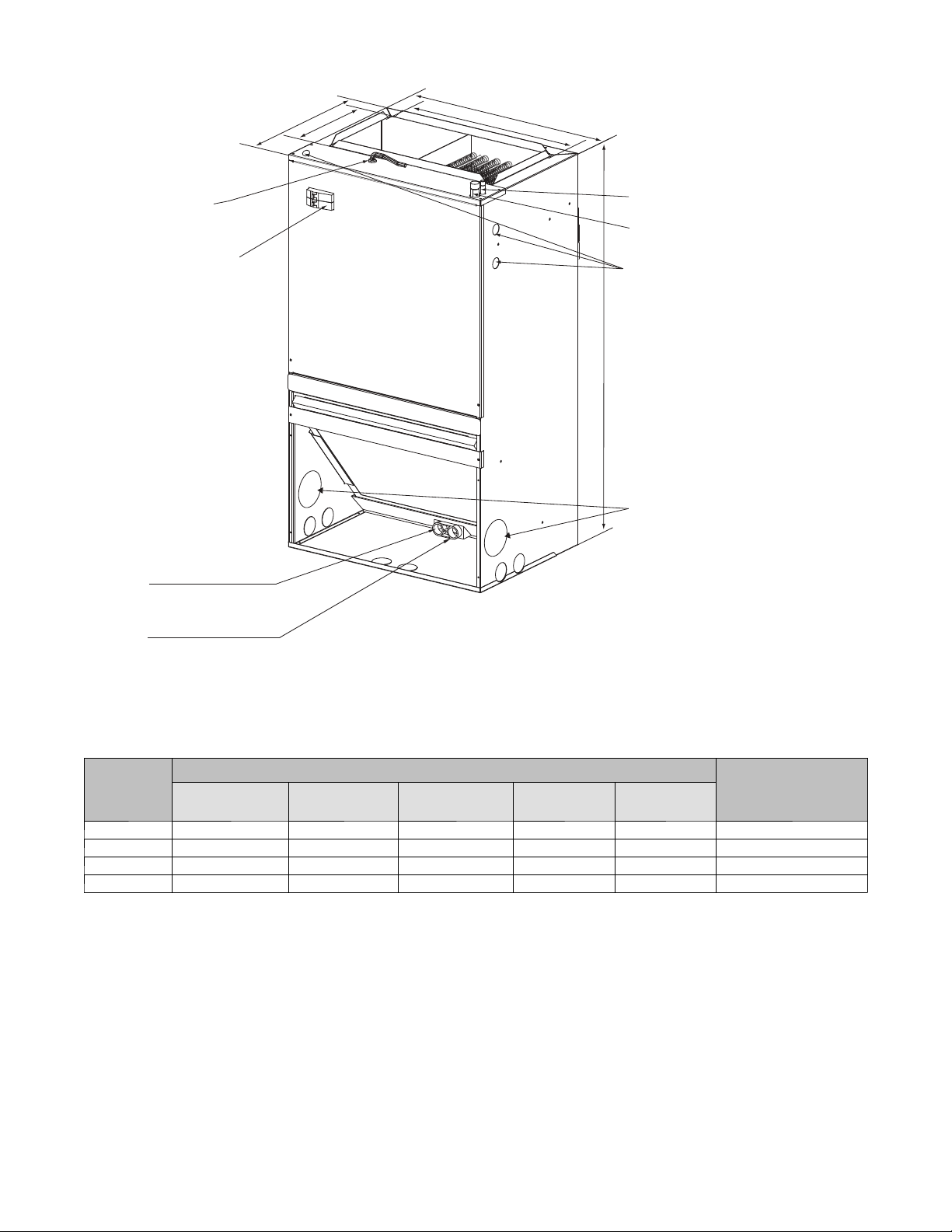
DIMENSIONS
Low voltage
connection
Breaker switch
(comes with accessory
electric heater only)
Front return shown. Units
may also be installed as
bottom return. See the
applications section for
more detail.
Primary drain connection
3/4” (19 mm) female
pipe thread (fpt)
D
D1
Return air opening
W
W1
Liquid line connection
copper (sweat)
Vapor line connection
copper (sweat)
High voltage connection
7/8” (22 mm) dia
knock outs
(both sides of unit)
Some heater sizes may
require a conduit larger than
H
the 7/8” (22 mm) opening;
in this situation the high-voltage
connection opening should be
enlarged to fit conduit.
Fresh air intakes,
3.4” (85.8 mm) dia
opening with
plastic cap
Auxiliary drain connection
3/4” (19 mm) female
pipe thread (fpt)
NOTE: Hand tighten only
All units are vertical upflow only.
Equipment shown with field-installed electric heat.
Fig. 1 -- Dimensional Drawing with Circuit Breaker
DIMENSIONAL DATA
Dimensions- In. (mm)
Model Size
18, 19 36-1/2 (928) 20-1/2 (521) 17-2/5 (452) 15 (381) 9-1/2 (242) 88 / 99 (40 / 45)
24, 25 36-1/2 (928) 20-1/2 (521) 17-2/5 (452) 15 (381) 9-1/2 (242) 88 / 99 (40 / 45)
30, 31 39-1/2 (1004) 22 (559) 18-4/5 (478) 19 (483) 9-1/2 (242) 110/ 121 (50 / 55)
36, 37 39-1/2 (1004) 22 (559) 18-4/5 (478) 19 (483) 9-1/2 (242) 110/ 121 (50 / 55)
Unit He ight
H
Unit Width
W
Unit Width
W1
Unit Depth
D
Unit Depth
D1
Unit Weight /
Shipping Weight
Lbs. (kg)
A150161
3
Page 4

SPECIFICATIONS
Unit Size
FFMANP0 18 24 30 36
Nominal Cooling Capacity (BTUH) 18,000 24,000 30,000 36,000
COIL
Puron- Refrigerant metering Device * (Piston) 50 57 65 72
Fins Per In. 17 17 17 17
Face Area Ft
Coil Configuration Slope
BLOWER & MOTOR
Air Discharge Upflow
Blower Type Direct Drive
CFM (Nominal) 600 800 1000 1200
Motor Type PSC PSC PSC PSC
Motor HP 1/6 1/4 1/3 1/2
Rated RPM 1075 1075 1075 1075
Motor Speeds 3 3 3 3
FILTER
Field Installed
CONNECTIONS (Sweat)
Suction --- in. (mm) 3/4 In. (19 mm)
Liquid --- in. (mm) 3/8 In. (9.5 mm)
Condensate (FPT) In. (mm) 3/4 In. (19 mm)
ELECTRICAL DATA
Voltage 208/230 208/230 208/230 208/230
Hertz 60 60 60 60
Circuit Amps 0.8 1.0 1.28 1.8
Minimum Circuit Ampacity 1 1.3 1.6 2.3
Maximum Circuit Protector 15 (A) 15 (A) 15 (A) 15 (A)
2
2.1 2.1 3.0 3.0
16x20x1
(406x508x25)
16x20x1
(406x508x25)
20x20x1
(508x508x25)
20x20x1
(508x508x25)
* The piston included with the fan coil is unique to this product and CANNOT be replaced with the piston shipped with outdoor unit. Refer to the AHRI ratings
to check if your combination can use the piston shipped with the unit or requires an accessory TXV.
Unit Size
FFMANP0 19 25 31 37
Nominal Cooling Capacity (BTUH) 18,000 24,000 30,000 36,000
COIL
Puron- Refrigerant metering Device TXV
Fins Per In. 17 17 17 17
Face Area Ft
Coil Configuration Slope
BLOWER & MOTOR
Air Discharge Upflow
Blower Type Direct Drive
CFM (Nominal) 600 800 1000 1200
Motor Type ECM ECM ECM ECM
Motor HP 1/3 1/3 1/2 1/2
Rated RPM 1050 1050 1050 1050
Motor Speeds 5 5 5 5
FILTER
Field Installed
CONNECTIONS (Sweat)
Suction --- in. (mm) 3/4 In. (19 mm)
Liquid --- in. (mm) 3/8 In. (9.5 mm)
Condensate (FPT) In. (mm) 3/4 In. (19 mm)
ELECTRICAL DATA
Voltage 208/230 208/230 208/230 208/230
Hertz 60 60 60 60
Circuit Amps 1.9 1.9 2.7 2.7
Minimum Circuit Ampacity 2.4 2.4 3.4 3.4
Maximum Circuit Protector 15 (A) 15 (A) 15 (A) 15 (A)
2
2.1 2.1 3.0 3.0
16x20x1
(406x508x25)
16x20x1
(406x508x25)
20x20x1
(508x508x25)
20x20x1
(508x508x25)
4
Page 5

PERFORMANCE DATA
PSC-- AIRFLOW PERFORMANCE (STANDARD CFM)
MODEL
SIZE
18
24
30
36
--- Shaded boxes represent airflow ou tside the required 300-450 cfm/ton.
NOTES:
1. Airflow based upon dry coil at 230V with no electric heat and fa ctory --- approved filter.
2. Airflow is equivalent for front or bottom return configurations.
BLOWER
SPEEDS
High 776 733 695 653 610 564 525 464
Med 661 624 585 546 502 454 415 354
Low 565 529 487 448 405 353 299 244
High 917 881 830 790 739 687 631 564
Med 819 785 745 703 654 604 544 480
Low 668 631 591 551 506 464 403 343
High 1236 1176 1115 1064 1000 936 861 793
Med 1113 1065 1014 962 908 842 772 701
Low 935 894 852 807 755 694 631 561
High 1350 1292 1228 1167 1108 1045 981 902
Med 1266 1198 1139 1088 1029 970 905 831
Low 1115 1066 1015 966 918 861 801 722
0 0.1 0.2 0.3 0.4 0.5 0.6 0.7
ECM AIRFLOW PERFORMANCE (STANDARD CFM)
MODEL SIZE BLOWER SPEEDS
Tap ( 5 ) 884 854 833 803 771 737 700 668 632
Tap ( 4 ) 796 767 737 709 675 645 612 579 538
19
25
31
37
--- Shaded boxes represent airflow ou tside the required 300-450 cfm/ton.
NOTES:
1. Airflow based upon dry coil at 230V with no electric heat and factory---approved filter. For 19, 25, 31 and 37 sizes, a irflow at 208V is approximately the same
as 230V because the multi--- tap ECM motor is a constant torque motor. The torque doesn’t drop off at the speeds in which the motor operates.
2. Airflow is equivalent for front or bottom return configurations.
Tap ( 3 ) 714 681 654 616 588 555 527 494 459
Tap ( 2 ) - Fa c t o r y 653 619 584 558 525 494 463 434 396
Tap ( 1 ) 581 545 511 472 440 407 374 344 329
Tap ( 5 ) 884 854 833 803 771 737 700 668 632
Tap ( 4 ) - Fa c t o r y 796 767 737 709 675 645 612 579 538
Tap ( 3 ) 714 681 654 616 588 555 527 494 459
Tap ( 2 ) 653 619 584 558 525 494 463 434 396
Tap ( 1 ) 581 545 511 472 440 407 374 344 329
Tap ( 5 ) 1309 1272 1236 1200 1164 1125 1088 1051 1010
Tap ( 4 ) 1122 1088 1056 1022 986 950 915 877 836
Tap ( 3 ) 1109 1073 1038 1003 973 937 901 867 828
Tap ( 2 ) - Fa c t o r y 1010 975 941 904 869 835 793 751 704
Tap ( 1 ) 936 899 862 833 793 755 710 664 619
Tap ( 5 ) 1309 1272 1236 1200 1164 1125 1088 1051 1010
Tap ( 4 ) - Fa c t o r y 1122 1088 1056 1022 986 950 915 877 836
Tap ( 3 ) 1109 1073 1038 1003 973 937 901 867 828
Tap ( 2 ) 1010 975 941 904 869 835 793 751 704
Tap ( 1 ) 936 899 862 833 793 755 710 664 619
0 0.1 0.2 0.3 0.4 0.5 0.6 0.7 0.8
EXTERNAL STATIC PRESSURE (In. W.C.)
EXTERNAL STATIC PRESSURE (IN WC.)
AIRFLOW PERFORMANCE (CFM)
Size Min Max
18 / 19 450 675
24 / 25 600 900
30 / 31 750 1125
36 / 37 900 1350
CFM
5
Page 6

PERFORMANCE DATA (CONT.)
GROSS COOLING CAPACITIES (mbh)
UNIT
SIZE
18 /
19
24 /
25
30 /
31
36 /
37
CFM --- C u b i c F t p e r M i n u t e EWB --- Entering Wet Bulb _F(_C) LWB --- L e a v in g W e t B u l b _F(_C) TC --- Gross Cooling Ca pacity 1000 Btuh
SHC --- Gross Sen sible Capacity 1000
Btuh
NOTES:
INDOOR
COIL AIR
CFM EWB TC SHC BF TC SHC BF TC SHC BF TC SHC BF TC SHC BF
72 (22) 38 18 0.00 35 17 0.00 31 15 0.00 27 14 0.00 22 12 0.00
67 (19) 32 19 0.00 28 18 0.00 25 16 0.00 20 14 0.00 15 12 0.00
525
62 (17) 26 20 0.00 22 18 0.00 19 17 0.01 15 15 0.07 13 13 0.21
72 (22) 42 20 0.00 38 18 0.00 34 17 0.00 30 15 0.00 24 13 0.00
67 (19) 34 21 0.00 31 19 0.00 26 17 0.00 22 16 0.00 17 14 0.01
600
62 (17) 28 22 0.01 24 20 0.01 20 19 0.01 17 17 0.08 14 14 0.22
72 (22) 45 21 0.00 41 20 0.00 37 18 0.00 32 16 0.00 26 14 0.00
67 (19) 37 23 0.01 33 21 0.01 29 19 0.01 24 17 0.01 18 15 0.01
675
62 (17) 30 24 0.01 26 22 0.01 22 20 0.01 19 19 0.10 16 16 0.24
72 (22) 46 22 0.00 43 20 0.00 38 19 0.00 33 17 0.00 27 15 0.00
67 (19) 38 24 0.01 35 22 0.01 30 20 0.01 25 18 0.01 19 16 0.01
700
62 (17) 31 25 0.01 27 24 0.01 23 22 0.02 20 20 0.11 17 17 0.24
72 (22) 50 24 0.00 46 22 0.00 41 20 0.01 36 18 0.01 30 16 0.01
67 (19) 41 26 0.01 37 24 0.01 32 22 0.01 27 20 0.01 21 18 0.02
800
62 (17) 34 28 0.01 30 26 0.01 25 25 0.03 22 22 0.14 19 19 0.26
72 (22) 53 25 0.01 48 24 0.01 44 22 0.01 38 20 0.01 32 17 0.01
67 (19) 44 28 0.01 39 26 0.01 34 24 0.01 29 22 0.02 22 19 0.02
900
62 (17) 36 30 0.02 32 28 0.02 27 27 0.05 24 24 0.16 21 21 0.28
72 (22) 67 33 0.00 61 30 0.00 54 27 0.00 46 23 0.00 37 20 0.00
67 (19) 55 34 0.01 49 31 0.01 41 28 0.01 33 24 0.01 23 20 0.01
875
62 (17) 44 35 0.01 38 32 0.01 30 28 0.01 24 24 0.07 20 20 0.23
72 (22) 74 37 0.00 67 33 0.00 59 30 0.00 50 26 0.00 40 22 0.01
67 (19) 61 38 0.01 54 34 0.01 46 31 0.01 37 27 0.01 25 22 0.01
1000
62 (17) 49 39 0.01 42 35 0.01 34 31 0.02 27 27 0.08 22 22 0.24
72 (22) 79 39 0.00 72 36 0.00 63 32 0.01 54 28 0.01 43 24 0.01
67 (19) 65 41 0.01 57 37 0.01 49 33 0.01 39 29 0.01 28 24 0.02
1100
62 (17) 52 42 0.02 45 38 0.02 36 34 0.02 29 29 0.09 24 24 0.25
72 (22) 73 36 0.00 67 33 0.00 59 29 0.01 51 26 0.01 41 22 0.01
67 (19) 60 38 0.01 54 34 0.01 46 31 0.01 37 27 0.01 27 23 0.02
1050
62 (17) 49 39 0.01 42 36 0.01 34 32 0.02 28 28 0.09 23 23 0.24
72 (22) 80 39 0.00 73 36 0.00 65 32 0.01 55 28 0.01 45 24 0.01
67 (19) 66 41 0.02 58 38 0.02 50 34 0.02 41 30 0.02 30 26 0.02
1200
62 (17) 53 43 0.02 46 40 0.02 38 36 0.02 32 32 0.11 26 26 0.25
72 (22) 85 42 0.00 78 39 0.01 69 35 0.01 59 31 0.02 48 27 0.02
67 (19) 71 45 0.02 63 41 0.02 54 37 0.02 44 33 0.02 32 28 0.03
1350
62 (17) 57 47 0.02 49 44 0.02 41 39 0.03 35 35 0.12 29 29 0.26
35 (2) 40 (4) 45 (7) 50 (10) 55 (13)
BF --- B y pa s s F a c to r MBH --- 1000 Btuh
1. Contact manufacturer for cooling capacities at conditions
other than shown in table.
2. Formulas:
Leaving db = entering db --sensible heat cap.
Leaving wb = wb corresponding to enthalpy of air leaving
coil (h
h
)
lwb
lwb=hewb
--total capacity (Btuh)
4.5xCFM
where h
= enthalpy of air entering coil. Direct interpola-
ewb
tion is permissible. Do not extrapolate.
3. SHC is based on 80_F(27_C) db temperature of air enter-
ing coil. Below 80_F(27_C) db, subtract (Correction Fact-
or x CFM) from SHC. Above 80_F(27_C) db, add (Cor-
rectionFactorxCFM)toSHC.
4. Bypass Factor = 0 indicates no psychometric solution. Use
bypass factor of next lower EWB for approximation.
SATURATED TEMPERATURE LEAVING EVAPORATOR _F(_C)
SHC CORRECTION FACTOR
ENTERING AIR DRY -- BULB TEMPERATURE (_F)
79 78 77 76 75 Under 75
81 82 83 84 85 Over 85
ENTERING AIR DRY -- BULB TEMPERATURE (_C)
26 25 25 24 24 Under 75
27 28 28 29 29 Over 85
1.09 x CFM
BYPASS
FACTOR
0.10 .098 1.96 2.94 3.92 4.91
0.20 0.87 1.74 2.62 3.49 4.36
0.30 0.76 1.53 2.29 3.05 3.82
Interpolation is permissible.
Correction Factor = 1.09 x (1 --- BF) x (db --- 80)
Correction Factor
Use
formula
shown
below
6
Page 7

PERFORMANCE DATA (CONT.)
ESTIMATED SOUND POWER LEVEL (dBA)
CONDITIONS OCTAVE BAND CENTER FREQUENCY
UNIT SIZE
18, 19 600 0.25 46 52.1 48.9 51.8 52.5 51.7 49.7
24, 25 800 0.25 54.1 57.1 58.6 59 61.5 59.8 57
30, 31 1000 0.25 51.6 52.6 52.6 53.3 56.1 52.8 59.7
36, 37 1200 0.25 52.6 52.3 54.6 54.3 57.2 53.8 50.4
* Estimated sound power levelshave been derived using the method described in the 1987 ASHRAE HVAC Systems & Applications Handbook,Chapter 52,p. 52.7.
ELECTRICAL DATA FOR FFMANP(018,024,030,036) PSC MOTOR UNITS WITH ELECTRIC HEAT
Heat
Kit
Model
EHK2-05B
EHK2-08B 7.5 22.2 25.6 34.9 40.1 50 50 8 8 10 10 76 77
EHK2-10B 10 24.6 32.8 46.2 53.1 60 60 6 6 10 10 92 92
EHK2-05B
EHK2-08B 7.5 22.2 25.6 35.2 40.4 50 50 8 8 10 10 76 76
EHK2-10B 10 24.6 32.8 46.4 53.4 60 60 6 6 10 10 91 92
EHK2-05B
EHK2-08B 7.5 22.2 25.6 35.5 40.7 50 50 8 8 10 10 75 76
EHK2-10B 10 24.6 32.8 46.8 53.7 60 60 6 6 10 10 91 91
EHK2-05B
EHK2-08B 7.5 22.2 25.6 36.2 41.4 50 50 8 8 10 10 74 74
EHK2-10B 10 24.6 32.8 47.4 54.4 60 60 6 6 10 10 90 90
* †† Copper wire must be used. If other than uncoated (non ---plated), 75_C ambient, copper wire (solid wire for 10 AWG and smaller, stranded wire for larger
than 10 AWG) is used, consult applicable tables of the National electric Code (ANSI/NGPA 70).
* ‡‡ Length shown is as measured 1 way along wire path between unit and service panel for a voltage drop not to exceed 2%.
CFM Ext Static Pressure 63 125 250 500 1000 2000 4000
MAX. Fuse
or Breaker
H e a t --- K i t
Ampacity
(HACR)
Min Wire
Size
(AWG) ††
Min Ground
Wire Size
Max Wire
Length (Ft)
‡‡
Used
on
Size
018
024
030
036
Nominal
Heat
Capacity
@ 240V
KW lbs. (kg) 208 240 208 240 208 240 208 240 208 240 208 240
5
5
5
5
Ship-
ping
Weight
5.1 (2.3)
5.1 (2.3)
5.1 (2.3)
5.1 (2.3)
Heater
Capacity
(MBH)
12.3 16.4 23.6 27.1 30 30 10 10 10 10 73 74
12.3 16.4 23.9 27.3 30 30 10 10 10 10 73 73
12.3 16.4 24.2 27.7 30 30 10 10 10 10 72 72
12.3 16.4 24.9 28.3 30 30 10 10 10 10 70 71
Minimum
Circuit
Ampacity
(MCA)
ELECTRICAL DATA FOR FFMANP(019,025,031,037) ECM MOTOR UNITS WITH ELECTRIC HEAT
Nominal
Heat
Kit
Model
EHK2-05B
EHK2-08B 7.5 22.2 25.6 36.3 41.5 50 50 8 8 10 10 73 74
EHK2-10B 10 24.6 32.8 47.6 54.5 60 60 6 6 10 10 89 90
EHK2-05B
EHK2-08B 7.5 22.2 25.6 36.3 41.5 50 50 8 8 10 10 73 74
EHK2-10B 10 24.6 32.8 47.6 54.5 60 60 6 6 10 10 89 90
EHK2-05B
EHK2-08B 7.5 22.2 25.6 37.3 42.5 50 50 8 8 10 10 71 72
EHK2-10B 10 24.6 32.8 48.6 55.5 60 60 6 6 10 10 87 88
EHK2-05B
EHK2-08B 7.5 22.2 25.6 37.3 42.5 50 50 8 8 10 10 71 72
EHK2-10B 10 24.6 32.8 48.6 55.5 60 60 6 6 10 10 87 88
* †† Copper wire must be used. If other than uncoated (non ---plated), 75_C ambient, copper wire (solid wire for 10 AWG and smaller, stranded wire for larger
than 10 AWG) is used, consult applicable tables of the National electric Code (ANSI/NGPA 70).
* ‡‡ Length shown is as measured 1 way along wire path between unit and service panel for a voltage drop not to exceed 2%.
Used
on
Size
019
025
031
037
Heat
Capacity
@ 240V
KW lbs. (kg) 208 240 208 240 208 240 208 240 208 240 208 240
5
5
5
5
Ship-
ping
Weight
5.1 (2.3)
5.1 (2.3)
5.1 (2.3)
5.1 (2.3)
Heater
Capacity
(MBH)
12.3 16.4 25 28.5 30 30 10 10 10 10 69 70
12.3 16.4 25 28.5 30 30 10 10 10 10 69 70
12.3 16.4 26 29.5 30 30 10 10 10 10 67 68
12.3 16.4 26 29.5 30 30 10 10 10 10 67 68
Minimum
Circuit
Ampacity
(MCA)
MAX. Fuse
or Breaker
H e a t --- K i t
Ampacity
(HACR)
Min Wire
Size
(AWG) ††
Min Ground
Wire Size
Max Wire
Length (Ft)
‡‡
7
Page 8

OTHER ACCESSORIES
Kit Number Description Used on sizes
KFBLG0106LGL Louvered Wall Panel with Frame (6 pack) 18, 19, 24, 25
KFBLG0206LGL Louvered Wall Panel with Frame (6 pack) 30, 31, 36, 37
KSATX0601HSO TXV Kit R-22 All
KSATX201PUR TXV Kit Puron (R-410A) 18, 19, 24, 25, 30, 31
KSATX301PUR TXV Kit Puron (R-401A) 36, 37
KFAET0150ETK PVC Condensate Trap Kit (50 pack) All
KFARA0110LGL Return Air Opening Grille (10 pack) 18, 19, 24, 25
KFARA0210LGL Return Air Opening Grille (10 pack) 30, 31, 36, 37
Copyright 2016 Carrier Corp. D 7310 W. Morris St. D Indianapolis, IN 46231 Edition Date: 01/16
Manufacturer reserves the right to change, at any time, specifications and designs without notice and without obligations.
8
Catalog No:FFMA--- 05PD
Replaces: FFMA ---04PD
 Loading...