

Page 1
50ZPC
Single---Packaged Air Conditioner System
With Puronr (R---410A) Refrigerant Single Phase
2 to 5 Nominal Tons (Sizes 024 ---060)
Product Data
such as coil cleaning are sped up with the multiple access side
panels.
NO--RUST BASEPAN WITH INTEGRATED DRAIN PAN is
standard on all units. The unit features a tough, hightech,
composite material basepan with integrated drain pan. The
composite material eliminates the potential problems of rust and
premature replacement which are common with standard metal
basepans.
DURABLE PRE--PAINTED STEEL CABINET protects
against harsh weather. The watertight construction and corrosion-resistant finish will keep it looking like new for years. The paint
treatment process ensures quality protection against the elements.
A compact, low-- profile design utilizes a louvered coil enclosure
for protection against vandalism and hail damage.
INDOOR AIR QUALITY is designed into the unit. A sloped
drain pan minimizes the amount of standing water inside the unit,
which limits mold and mildew growth. The drain pan is made of a
rust--proof material and will not deteriorate or release foreign
matter into the airstream.
A10165
Unit 50ZPC
Certified to leak 2% or less of nominal air conditioning CFM
delivered when pressurized to 1--in. W.C. with all present air
inlets, air outlets, and condensate drain port(s) sealed.
This unit is a packaged air conditioner for manufactured housing,
residential, and light commercial applications. The unit design is
the result of our firm commitment to the development of the finest
air conditioners that modern technology can offer.
The unit is built in one basic cabinet size and features a round or
rectangular side--by--side duct configuration.
FEATURES/BENEFITS
FACTORY--ASSEMBLED PACKAGE is a compact, fully
self--contained, electric cooling unit with horizontal supply and
return ducts. The unit is available in a variety of standard cooling
sizes to meet residential and light commercial requirements. Unit
installs easily on a ground level pad.
EASY TO INSTALL -- The unit is small, compact, and easy to
handle. Every unit has an identical 32 x 51--in. (813 x 1295 mm)
footprint to make planning simple. The concise design uses less
sheet metal and makes the unit lighter than other units. The unit
can be easily positioned on the job site with the hand holds built
into the unit basepan.
AERODYNAMIC FAN BLADE DESIGN reduces the overall
sound now as low as 72dBA.
SERVICE ACCESS makes installation and maintenance quicker
and easier. This unit is designed to be serviced from both the side
and front. The design allows easy access for installation and
maintenance procedures on the unit. Routine maintenance tasks
LIGHTWEIGHT, COMPACT CONSTRUCTION is ideal for
manufactured housing and residential applications. This unit is one
of the lightest, most compact packaged units ever designed. It’s
light weight (230 lb [104 kg]) for the 024 size) makes the unit
easier to handle. The low height keeps ductwork connections to a
minimum and makes units less visible.
This unit utilizes a structural beam design to form the four sides of
the cabinet. Only 12 different pieces of sheet metal are used in the
unit construction to simplify the unit for greater reliability.
EFFICIENT, DEPENDABLE PERFORMANCE with durable
compressors designed for efficiency. The unit offers up to 14.5
SEER (Seasonal Energy Efficiency Ratio) cooling performance
efficiencies. This performance level can reduce cooling expenses
by as much as 30% compared to older cooling equipment.
DURABLE, DEPENDABLE, COMPRESSORS are designed
for high efficiency. Each compressor is hermetically sealed against
contamination to help promote longer life and dependable
operation. Vibration isolation provides quiet operation.
Compressors have internal overcurrent protection.
DIRECT--DRIVE MULTISPEED, BLOWER MOTOR is
standard on all models. It’s high efficiency design ensures high
performance with most duct systems.
DIRECT--DRIVE, PSC CONDENSER--FAN MOTORS are
designed to help reduce energy consumption and provide for
cooling operation down to 40F(4.4° C).
1
Page 2
REFRIGERANT SYSTEM is designed to provide dependability.
Liquid refrigerant filter driers are used to promote clean,
unrestricted operation. Each unit leaves the factory with a full
refrigerant charge. Refrigerant service connections make checking
operating pressures easier.
ACCESSORY ELECTRIC HEATERS —Avarietyof
accessory electric heaters are available. These heaters are comprised
of a separate heater module mounted on the blower inlet and
remote mounted controls located in the unit control box. Single
point electrical connections are available for powering both the
heater and the unit.
TABLE OF CONTENTS
FEATURES/BENEFITS 1--2.......................................................................................
MODEL NUMBER NOMENCLATURE 2...........................................................................
AHRI CAPACITIES 3............................................................................................
PHYSICAL DATA 3.............................................................................................
ACCESSORIES 4...............................................................................................
BASE UNIT DIMENSIONS 5--6...................................................................................
SELECTION PROCEDURE 7.....................................................................................
PERFORMANCE DATA 8--12.....................................................................................
50ZPC
TYPICAL WIRING SCHEMATICS 13..............................................................................
ELECTRICAL DATA 15.........................................................................................
OPERATING SEQUENCE 15.....................................................................................
APPLICATION DA TA 16.........................................................................................
TYPICAL INSTALLATION 15....................................................................................
GUIDE SPECIFICATIONS 17.....................................................................................
Page
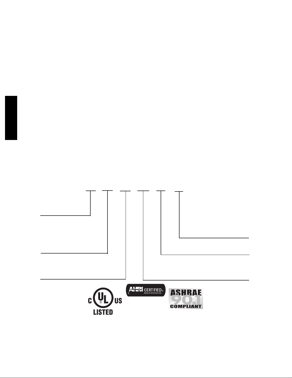
MODEL NUMBER NOMENCLATURE
024
Typ e o f U ni t
50ZPC---Single Packaged Air
Conditioner System
Nominal Cooling Capacity
024 --- 2.0 Tons
030 --- 2.5 Tons
036 --- 3.0 Tons
042 --- 3.5 Tons
048 --- 4.0 Tons
060 --- 5.0 Tons
N/A
50ZPC
--- --- ---
3
Electrical Supply
3 --- 208/230 ---1 ---60
Use of the AHRI Certified
TM Mark indicates a
manufacturer’s
participation in the
program For verification
of certification for individual
products, go to
www.ahridirectory.org.
0
--- ---
Options
TP --- B ase unit with tin plated indoor coil hairpins
Only used if ordering an option
Series
2
Page 3
AHRI* CAPACITY RATINGS
Cooling Capacities and Efficiencies
NET COOLING
UNIT SIZE NOMINAL TONS STANDARD CFM
024 2 800 22400 11.5 14
030 2.5 1000 28600 11.5 14
036 3 1200 35000 11.5 14
042 3.5 1400 41000 11.5 14.5
048 4 1600 47000 11.5 14
060 5 1850 54000 11.3 14
LEGEND
d B --- --- --- S o u n d L e v e l s ( d e c i b e l s )
db—Dry Bulb
SEER—Seasonal Energy Efficiency Ratio
wb—Wet Bulb
C O P --- --- --- C o e f f i cien t o f Pe r f o r m a n c e
* Air Conditioning Heating & Refrigeration Institute
† At ”A” conditions --- --- 80° F (26.7° C) indoor db/67° F
(19.4° C) indoor wb & 95° F (35° C) outdoor db.
** Rated in accordance with U.S. Government DOE
Department of Energy) test procedures and/or AHRI
Standards 210/240 ------ --- 08, 270 ---1995.
A--Weighted Sound Power Level (dBA)
UNIT SIZE STANDARD RATING (dBA)
024 72 54.4 54.9 58.8 67.5 53.7 48.5 39.4
030 75 55.4 63.9 62.8 59.0 54.7 45.5 37.9
036 75 60.4 58.9 62.8 63.0 58.7 52.5 45.4
042 75 59.9 64.4 69.3 68.0 65.2 63.0 60.4
048 76 58.4 61.9 65.3 65.5 59.7 55.0 47.4
060 80 72.9 65.4 68.8 70.5 65.2 60.5 50.9
CAPACITY
AT 95° F (35° c)
EER† SEER**
(Btuh)
Notes:
1. Ratings are net values, reflecting the effects of circulating fan heat.
Ratings are based on:
Cooling Standard: 80° F (26.7° C ) db, 67° F wb (19.4° C) indoor
e n t e r i n g --- --- --- a i r
t e m p e r a t u r e an d 9 5 ° F d b (35° C ) ou tdoor e n t e r i n g --- --- --- a i r te m p e r a t u r e .
2. Before purchasing this appliance, read important energy cost and efficiency information available from your retailer.
TYPICAL OCTAVE BAND SPECTRUM (dBA without tone adjustment)
125 250 500 1000 2000 4000 8000
50ZPC
PHYSICAL DATA
UNIT SIZE 024 030 036 042 048 060
NOMINAL CAPACITY (ton) 2 2.5 3 3.5 4 5
SHIPPING WEIGHT (lb)
COMPRESSOR TYPE RECIPROCATING SCROLL
REFRIGERANT R-410A
REFRIGERANT QUANTITY (lb)
METERING DEVICE ID Piston TXV
ORIFICE OD (in.)
OUTDOOR COIL
ROWS...FINS/in.
FACE AREA (s q. ft)
OUTDOOR FAN
NOMINAL AIRFLOW (CFM)
DIAMETER (in.)
DIAMETER (mm)
MOTOR HP (RPM)
INDOOR COIL
ROWS...FINS/in.
FACE AREA (s q. ft)
INDOOR BLOWER
NOMINAL COOLING AIRFLOW
NOMINAL SIZE W x D (in.)
HIGH-PRESSURE SWITCH (psig)
*Required filter sizes shown are based on the AHRI (Air Conditioning, Heating and Refrigeration Institute) rated air flow at a velocity of 300 ft/min for throwaway
type or 450 ft/min for high capacity type. Recommended filters are 1 ---in. (25.4 mm) thick.
(CFM)
MOTOR (HP)
CUTOUT
RESET (AUTO)
RETURN-AIR FILTERS
THR OWAWAY ( in.)
(kg)
QUANTITY (kg)
(mm)
(mm)
(mm)
286
130
3.3
1.5
0.057
1.45
1...20
9.1
2400
20
508
1/8 (825)
2...12
4.3
800
8x11
254 x 203
1/3
20x20x1
508x508x25
298
136
5.2
2.4
0.063
1.60
1...20
9.1
2400
20
508
1/8 (825)
3...12
4.3
1000
8x11
254 x 203
1/3
20x24x1
508x610x25
329
150
5.5
2.5
0.067
1.70
2...20
9.1
2700
20
508
1/4 (1100)
3...12
4.3
1200
9x12
279 x 229
1/2
650 +/- 15
420 +/- 25
24x30x1
610x762x25
352
160
7.3
3.3
0.076
1.93
2...20
10.2
2700
20
508
1/4 (1100)
3...12
4.9
1400
9x12
279 x 229
1/2
368
167
6.3
2.9
0.080
2.03
2...20
13.0
2700
20
508
1/4 (1100)
3...15
4.9
1600
11 x 12
279 x 229
3/4
24x36x1
610x914x25
402
183
7.5
3.4
N/A
2...20
15.5
3000
20
508
1/3 (1110)
3...15
6.1
1850
11 x 12
267 x 305
1
3
Page 4

OPTIONS AND ACCESSORIES
ITEM DESCRIPTION
Coil Options Base unit with tin pl ated indoor coil hairpins X
Compressor Start Kit
Corporate Thermostats
Crankcase Heater
Electric Heaters Electric Heat Supplement X
Low Ambient Kit
Time Guard II
*Refer to Price Page for application detail.
Accessory Electric Heaters
CATALOG
ORDERING NO.
50ZPC
CPHEATER125A0* 3.8 / 5.0 No 1
CPHEATER126A0* 3.8 / 5.0 Yes 1
CPHEATER127A0* 5.6 / 7.5 No 2
CPHEATER128A0*
CPHEATER129A0* 7.5 / 10.0 No 2
CPHEATER130A0* 7.5 / 10.0 Yes 2
CPHEATER131A0* 11.3 / 15.0 Yes 2
CPHEATER132A0* 15.0 / 20.0 Yes 2
=Approved combination
NOMINAL
CAPACITY
(kW)
5.6 / 7.5
FACTORY
INSTALLED
OPTION
Compressor Start Kit assists compressor start---up by providing
additional starting torque on sing phase units only.
Thermostats provide control for the system heating and cooling
functions.
Crankcase Heater provides anti ---floodback protection for low--load cooling applications.
Low Ambient Kit (Motormaster II Control) allows the use of mechanical cooling down to outdoor temperatures as low as 0°F
( ---18° C) when properly installed.
Automatically prevents the compressor from restarting for at least
4 minutes and 45 seconds after shutdown of the compressor. Not
required when a corporate programmable thermostat is applied.
USED WITH SIZES
CIRCUIT
BREAKER
(Y es/No)
ELECTRIC HEATERS (208/230 --SINGLE PHASE--60Hz)
Yes 2
STAGES 024 030 036 042 048 060
INSTALLED
ACCESSORY
FIELD
X
X
X*
X
X
Multiplication Factors
HEATER kW RATING VOLTAGE DISTRIBUTION MULTIPLICATION FACTOR
200 .69
240
Example: 15.0 kW (at 240v) heater on 208v
=15.0(.75multfactor)
= 11.25 capacity at 208v
208 .75
230 .92
240 1.00
4
Page 5
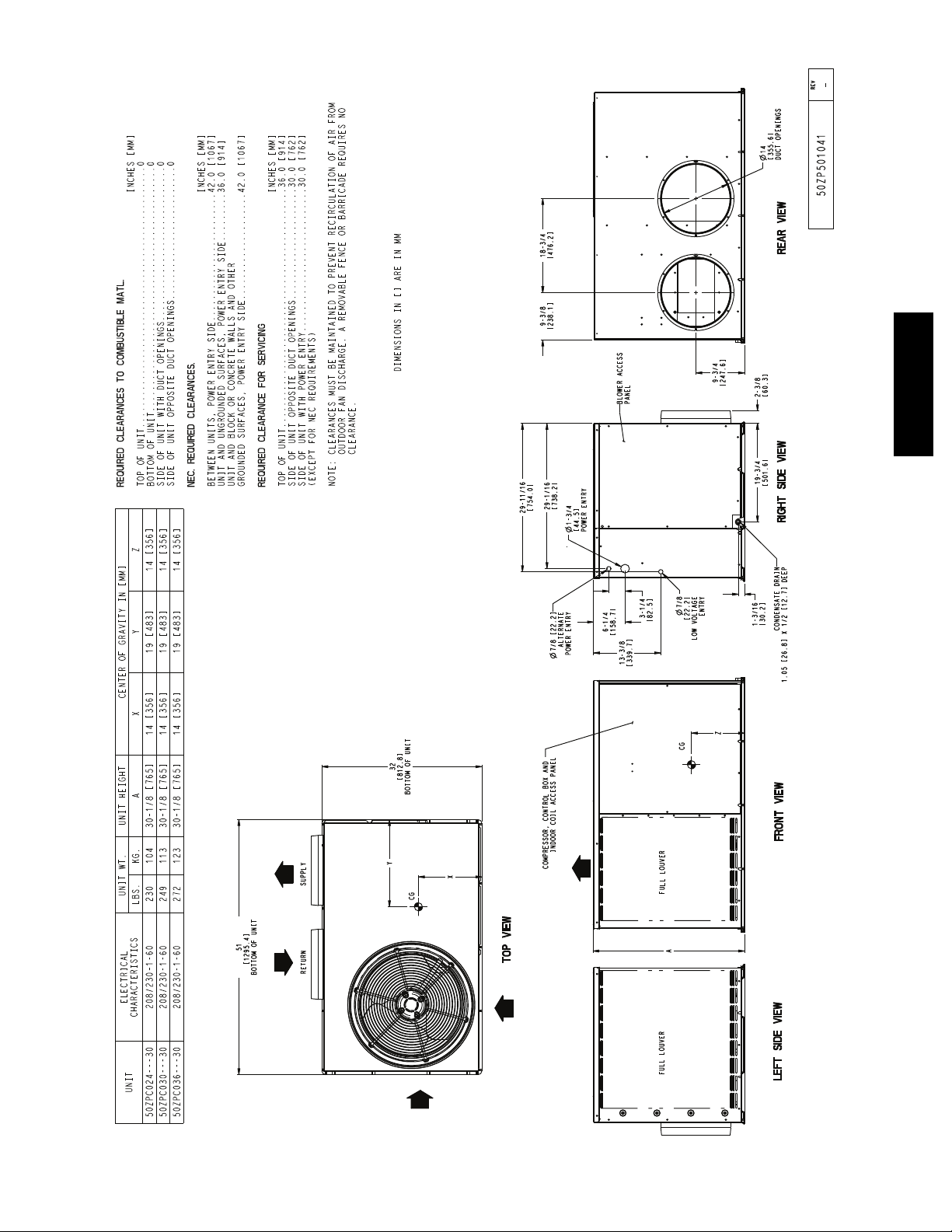
DIMENSIONAL DRAWINGS — 024--036
50ZPC
A14413
5
Page 6
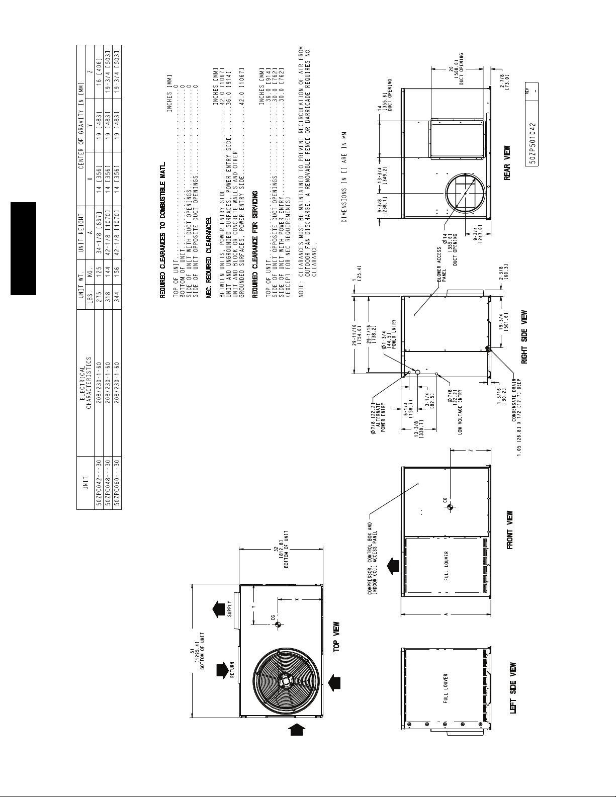
DIMENSIONAL DRAWINGS — 042--060
50ZPC
A14414
6
Page 7

SELECTION PROCEDURE
A. DETERMINE COOLING AND HEATING
REQUIREMENTS AT DESIGN CONDITIONS.
Given:
Required Cooling Capacity (TC) 34,000 Btuh..........
Sensible Heat Capacity (SHC) 25,000 Btuh............
Required Heating Capacity 15,000 Btuh...............
Outdoor Entering--Air Temperature 95° F(35° C)........
Indoor Entering--Air Temperature 80° F edb (26.7° C);...
67° F (19.4° C) ewb
Indoor--Air Quantity 1200 CFM.....................
External Static Pressure 0.20 IN. W.C..................
Electrical Characteristics (V--Ph--Hz) 230--1-- 60.........
B. SELECT UNIT BASED ON REQUIRED COOLING
CAPACITY (3 --TON EXAMPLE)
Enter Cooling Capacities table at condenser entering temperature
of 95° F(35° C), indoor air entering at 1200 CFM and 67° F
(19.4° C) ewb. The 036 unit provides a total cooling capacity of
34,500 Btuh and a sensible heat capacity of 26,040 Btuh.
For indoor--air temperature other than 80° F (26.7° C) edb,
calculate sensible heat capacity correction, as required, using the
formula found following the Cooling Capacities tables.
NOTE: Unit ratings are net capacities.
C. SELECT ELECTRIC HEAT.
The required heating capacity is 15,000 Btuh (given).
Determine the electric heat capacity in kW.
15,000 Btuh
3414 Btuh/kW
3.8 kW of heat required
=
Enter the Accessory Electric Heater table on page 4 for 208/230,
single--phase, 036 unit. The 5--kW heater at 240v most closely
satisfies the heating required. To calculate kW at 230 V, multiply
the heater kW by multiplication factor 0.92 found in the
Multiplication Factors table on page 4.
5 kW x 0.92 = 4.6 kW
4.6 kW x 3414 Btuh/kW = 15,704 Btuh
D. DETERMINE FAN SPEED AND POWER
REQUIREMENTS AT DESIGN CONDITIONS.
Before entering the air delivery tables, calculate the total static
pressure required. From the given, Filter Pressure Drop table, and
the Accessory Electric Heat Pressure Drop table find:
External static pressure 0.20 IN. W.C.
Filter 0.10 IN. W.C.
Electric Heat 0.04
IN. W.C.
Total static pressure 0.34 IN. W.C.
Enter the table for Dry Coil Air Delivery — Horizontal Discharge.
At 0.4 IN. W .C. external static pressure and medium speed, the
motor delivers 1236 CFM.
50ZPC
7
Page 8

Sys
KW
To t a l
Sys
KW
To t a l
50ZPC
Capacity MBtuh
KW
Sys
To t a l
Capacity MBtuh
KW
Sys
To t a l
Capacity MBtuh
Capacity MBtuh
KW
Sys
To t a l
Capacity MBtuh
KW
Sys
To t a l
Capacity MBtuh
KW
Sys
KW
Sys
To t a l
CONDENSER ENTERING AIR TEMPERATURES ° F (° C)
Capacity MBtuh
KW
Sys
To t a l
75 (24) 85 (29) 95 ( 35) 105 (41) 115 (46)
To t a l Sens Tot a l Sens Tot a l Sens Tot a l Sens To t a l Sens
Capacity MBtuh
(_C)
57 (14) 23.14 23.14 1.61 21.24 21.24 1.74 19.25 19.24 1.86 17.04 17.04 1.96 14.82 14.82 2.07
62 (17) 24.27 20.27 1.62 21.95 19.60 1.75 19.62 18.81 1.87 17.08 17.08 1.96 14.84 14.84 2.07
63 (17) 24.78 16.65 1.62 22.42 15.97 1.76 20.01 15.23 1.89 17.24 14.26 1.96 14.37 13.22 2.05
67 (19) 26.88 17.28 1.64 24.42 16.63 1.79 21.93 15.96 1.93 19.35 15.21 2.06 16.25 14.17 2.13
71 (22) 28.93 14.81 1.66 26.42 14.21 1.81 23.86 13.55 1.96 21.29 12.86 2.10 18.38 12.02 2.23
57 (14) 24.22 24.22 1.63 22.22 22.22 1.77 20.22 20.22 1.91 17.96 17.96 2.01 15.58 15.58 2.12
62 (17) 24.93 21.65 1.63 22.58 20.97 1.77 20.25 20.22 1.91 18.01 18.01 2.02 15.61 15.61 2.12
67 (19) 27.49 18.23 1.66 24.95 17.62 1.80 22.40 16.95 1.95 19.79 16.23 2.08 16.66 15.24 2.16
57 (14) 25.14 25.14 1.65 23.05 23.05 1.79 20.97 20.97 1.93 18.76 18.76 2.06 16.25 16.25 2.16
62 (17) 25.51 22.89 1.65 23.16 22.17 1.79 20.99 20.99 1.93 18.80 18.80 2.07 16.27 16.27 2.16
63 (17) 25.88 18.45 1.66 23.38 17.81 1.80 20.87 17.11 1.93 18.08 16.21 2.03 15.08 15.10 2.11
67 (19) 27.96 19.09 1.68 25.39 18.51 1.82 22.76 17.88 1.97 20.11 17.19 2.10 17.01 16.23 2.19
71 (22) 29.97 16.02 1.70 27.36 15.45 1.85 24.70 14.82 2.00 21.98 14.14 2.15 19.16 13.46 2.28
AIR
63 (17) 25.39 17.60 1.64 22.96 16.93 1.78 20.50 16.21 1.91 17.69 15.26 2.00 14.75 14.19 2.08
EWB _F
71 (22) 29.52 15.44 1.68 26.95 14.86 1.83 24.33 14.21 1.98 21.69 13.53 2.13 18.83 12.79 2.26
To t a l
CONDENSER ENTERING AIR TEMPERATURES ° F (° C)
Capacity MBtuh
KW
Sys
To t a l
75 (24) 85 (29) 95 (35) 105 (41) 115 (46)
To t a l Sens To t a l Sens To t a l Sens Tot a l Sens Tot a l Sens
Capacity MBtuh
(_C)
57 (14) 29.36 29.36 1.98 27.29 27.29 2.18 25.09 25.09 2.38 22.44 22.44 2.55 19.75 19.75 2.74
62 (17) 30.31 26.51 1.99 27.78 25.23 2.19 25.20 24.98 2.39 22.49 22.49 2.55 19.80 19.80 2.74
63 (17) 30.88 21.56 1.99 28.27 20.35 2.20 25.55 19.11 2.40 22.14 17.60 2.54 18.72 16.09 2.69
67 (19) 33.55 22.45 2.02 30.80 21.29 2.23 28.03 20.09 2.45 24.81 18.76 2.65 21.11 17.24 2.80
71 (22) 36.25 19.13 2.05 33.44 18.02 2.27 30.56 16.92 2.50 27.57 15.80 2.73 23.82 14.43 2.92
57 (14) 30.74 30.74 2.01 28.55 28.55 2.22 26.32 26.32 2.44 23.64 23.64 2.63 20.76 20.76 2.81
62 (17) 31.21 28.48 2.02 28.78 26.89 2.23 26.36 26.36 2.44 23.68 23.68 2.63 20.80 20.80 2.81
67 (19) 34.29 23.85 2.05 31.45 22.70 2.27 28.60 21.50 2.49 25.44 20.23 2.70 21.63 18.64 2.85
57 (14) 31.88 31.88 2.05 29.60 29.60 2.26 27.29 27.29 2.48 24.63 24.63 2.70 21.60 21.60 2.88
62 (17) 31.96 31.67 2.05 29.63 29.63 2.26 27.33 27.33 2.49 24.67 24.67 2.70 21.64 21.64 2.88
63 (17) 31.61 22.92 2.02 28.92 21.71 2.23 26.15 20.48 2.44 22.71 18.94 2.58 19.19 17.36 2.74
EWB _F
71 (22) 36.94 20.07 2.07 34.08 18.99 2.30 31.12 17.87 2.53 28.07 16.75 2.76 24.30 15.42 2.97
63 (17) 32.18 24.17 2.05 29.42 23.00 2.26 26.61 21.75 2.47 23.18 20.21 2.63 19.65 18.50 2.79
67 (19) 34.84 25.17 2.08 31.96 24.02 2.30 29.03 22.83 2.52 25.96 21.57 2.74 22.07 19.95 2.90
71 (22) 37.48 20.94 2.10 34.56 19.87 2.33 31.50 18.78 2.56 28.44 17.64 2.80 24.69 16.39 3.02
PERFORMANCE DATA
EVAPORATOR
Cooling Capacities
024
CFM
700
800
900
See Legend and Notes on page 11.
030
8
CFM
EVAPORATOR AIR
875
1000
1125
See Legend and Notes on page 11.
Page 9

Sys
KW
To t a l
Sys
KW
To t a l
Capacity MBtuh
KW
Sys
To t a l
Capacity MBtuh
KW
Sys
To t a l
50ZPC
Capacity MBtuh
KW
Sys
To t a l
Capacity MBtuh
Capacity MBtuh
KW
Sys
To t a l
Capacity MBtuh
KW
Sys
To t a l
CONDENSER ENTERING AIR TEMPERATURES ° F (° C)
Capacity MBtuh
KW
Sys
To t a l
75 (24) 85 (29) 95 (35) 105 (41) 115 (46)
To t a l Sens To t a l Sens To t a l Sens Tot a l Sens Tot a l Sens
Capacity MBtuh
(_C)
57 (14) 34.95 34.95 2.39 32.78 32.78 2.65 30.54 30.54 2.91 28.13 28.13 3.18 25.17 25.17 3.42
62 (17) 36.15 32.02 2.40 33.49 31.07 2.66 30.78 29.99 2.92 28.17 28.17 3.18 25.21 25.21 3.42
63 (17) 36.83 26.05 2.40 34.09 25.10 2.67 31.22 24.06 2.93 28.11 22.91 3.17 24.25 21.41 3.37
67 (19) 39.89 27.04 2.42 37.06 26.18 2.70 34.15 25.24 2.99 31.05 24.22 3.28 27.26 22.90 3.51
71 (22) 43.61 21.93 2.45 40.81 21.13 2.74 37.84 20.24 3.04 34.70 19.28 3.34 31.35 18.25 3.66
57 (14) 36.52 36.52 2.43 34.27 34.27 2.70 31.94 31.94 2.99 29.43 29.43 3.26 26.39 26.39 3.51
62 (17) 37.10 34.24 2.43 34.48 33.26 2.70 31.97 31.97 2.99 29.47 29.47 3.27 26.44 26.44 3.51
67 (19) 40.69 28.57 2.46 37.82 27.76 2.74 34.80 26.85 3.03 31.65 25.87 3.32 27.90 24.63 3.58
57 (14) 37.79 37.79 2.47 35.48 35.48 2.74 33.04 33.04 3.03 30.50 30.50 3.33 27.45 27.45 3.59
62 (17) 37.98 36.24 2.47 35.53 35.53 2.74 33.08 33.08 3.03 30.54 30.54 3.33 27.50 27.50 3.60
63 (17) 37.64 27.56 2.44 34.83 26.64 2.71 31.89 25.65 2.98 28.72 24.50 3.23 24.81 22.99 3.43
EWB _F
71 (22) 44.31 22.79 2.48 41.49 22.03 2.77 38.44 21.17 3.07 35.23 20.23 3.39 31.83 19.23 3.70
63 (17) 38.27 28.95 2.47 35.39 28.07 2.74 32.40 27.11 3.02 29.23 26.00 3.29 25.31 24.46 3.49
67 (19) 41.27 29.95 2.49 38.36 29.20 2.77 35.29 28.34 3.06 32.11 27.40 3.36 28.45 26.26 3.64
71 (22) 44.83 23.55 2.51 41.97 22.83 2.80 38.88 22.01 3.11 35.62 21.09 3.42 32.18 20.13 3.74
CONDENSER ENTERING AIR TEMPERATURES ° F (° C)
75 (24) 85 (29) 95 (35) 105 (41) 115 (46)
KW
Sys
To t a l
Capacity MBtuh
KW
Sys
To t a l
To t a l Sens To t a l Sens To t a l Sens Tot a l Sens Tot a l Sens
Capacity MBtuh
(_C)
57 (14) 41.68 41.68 2.75 38.94 38.94 3.11 35.98 35.98 3.49 32.25 32.25 3.87 28.66 28.66 4.32
62 (17) 42.95 38.93 2.75 39.78 36.79 3.12 36.43 34.57 3.50 32.28 32.28 3.87 28.71 28.71 4.32
63 (17) 43.70 31.61 2.75 40.44 29.72 3.12 36.99 27.79 3.51 32.43 25.38 3.87 27.98 23.06 4.30
67 (19) 47.16 32.78 2.77 43.74 30.91 3.13 40.27 29.04 3.52 36.10 26.97 3.96 31.37 24.61 4.39
71 (22) 51.59 26.51 2.78 47.98 24.89 3.15 44.33 23.26 3.55 40.57 21.60 3.99 36.10 19.78 4.49
57 (14) 43.43 43.43 2.79 40.56 40.56 3.15 37.56 37.56 3.55 33.84 33.84 3.94 30.06 30.06 4.39
62 (17) 44.02 41.66 2.79 40.84 39.39 3.16 37.60 37.60 3.55 33.90 33.90 3.94 30.11 30.11 4.40
67 (19) 48.06 34.74 2.81 44.57 32.83 3.17 41.00 30.90 3.56 37.08 28.93 4.01 32.09 26.48 4.45
57 (14) 44.86 44.86 2.83 41.89 41.89 3.19 38.82 38.82 3.59 35.20 35.20 4.02 31.25 31.25 4.47
62 (17) 45.00 44.04 2.83 41.94 41.94 3.20 38.88 38.88 3.59 35.25 35.25 4.02 31.28 31.28 4.47
63 (17) 44.60 33.50 2.79 41.26 31.57 3.16 37.77 29.61 3.55 33.24 27.21 3.92 28.66 24.78 4.36
EWB _F
71 (22) 52.46 27.65 2.82 48.78 26.00 3.19 45.03 24.35 3.59 41.21 22.67 4.03 36.86 20.91 4.53
63 (17) 45.28 35.25 2.83 41.88 33.29 3.20 38.36 31.31 3.59 33.90 28.93 3.98 29.21 26.39 4.41
67 (19) 48.74 36.57 2.84 45.17 34.62 3.21 41.56 32.62 3.60 37.71 30.65 4.05 32.66 28.22 4.50
71 (22) 53.13 28.71 2.86 49.38 27.04 3.23 45.55 25.35 3.63 41.66 23.65 4.07 37.49 21.93 4.58
COOLING CAPACITIES (CONT)
036
CFM
EVAPORATOR AIR
1050
1200
1350
See Legend and Notes on page 11.
042
9
CFM
EVAPORATOR AIR
1225
1400
1575
See Legend and Notes on page 11.
Page 10

Sys
KW
To t a l
Sys
KW
To t a l
50ZPC
Capacity MBtuh
KW
Sys
To t a l
Capacity MBtuh
KW
Sys
To t a l
Capacity MBtuh
Capacity MBtuh
KW
Sys
To t a l
Capacity MBtuh
KW
Sys
To t a l
Capacity MBtuh
KW
Sys
To t a l
CONDENSER ENTERING AIR TEMPERATURES ° F (° C)
Capacity MBtuh
KW
Sys
To t a l
75 (24) 85 (29) 95 (35) 105 (41) 115 (46)
To t a l Sens To t a l Sens To t a l Sens To t a l Sens Tot a l Sens
Capacity MBtuh
(_C)
57 (14) 46.69 46.69 3.18 43.96 43.96 3.55 41.20 41.20 3.97 38.15 38.15 4.45 34.26 34.26 4.96
62 (17) 48.24 40.86 3.19 45.07 40.07 3.56 41.86 39.18 3.99 38.39 38.02 4.46 34.32 34.32 4.97
63 (17) 49.13 33.18 3.19 45.86 32.38 3.57 42.55 31.50 4.00 38.89 30.43 4.47 34.04 28.78 4.95
67 (19) 53.03 34.45 3.21 49.63 33.69 3.59 46.16 32.87 4.03 42.51 31.94 4.54 38.08 30.67 5.10
71 (22) 58.07 27.87 3.25 54.53 27.15 3.63 50.89 26.37 4.07 47.09 25.48 4.58 43.08 24.48 5.17
57 (14) 48.69 48.69 3.24 45.86 45.86 3.62 42.97 42.97 4.06 39.87 39.87 4.56 35.98 35.98 5.08
62 (17) 49.45 43.78 3.24 46.24 42.96 3.62 43.08 42.83 4.06 39.93 39.93 4.56 36.04 36.04 5.08
67 (19) 54.04 36.51 3.27 50.57 35.78 3.65 47.00 35.00 4.09 43.31 34.10 4.60 39.07 33.00 5.18
57 (14) 50.32 50.32 3.30 47.39 47.39 3.68 44.38 44.38 4.12 41.24 41.24 4.63 37.45 37.45 5.19
62 (17) 50.52 46.35 3.30 47.46 47.46 3.68 44.44 44.44 4.12 41.29 41.29 4.63 37.50 37.50 5.19
63 (17) 50.14 35.19 3.25 46.79 34.40 3.62 43.38 33.54 4.06 39.71 32.52 4.55 34.85 30.91 5.04
EWB _F
71 (22) 59.08 29.08 3.31 55.45 28.38 3.69 51.71 27.61 4.13 47.83 26.75 4.64 43.74 25.74 5.24
63 (17) 50.90 37.05 3.30 47.50 36.30 3.68 44.02 35.46 4.12 40.35 34.49 4.62 35.52 32.90 5.12
67 (19) 54.81 38.44 3.33 51.26 37.75 3.70 47.64 36.98 4.14 43.89 36.11 4.65 39.74 35.07 5.24
71 (22) 59.83 30.17 3.37 56.13 29.51 3.75 52.32 28.76 4.19 48.35 27.90 4.70 44.21 26.91 5.30
CONDENSER ENTERING AIR TEMPERATURES ° F (° C)
75 (24) 85 (29) 95 (35) 105 (41) 115 (46)
KW
Sys
To t a l
50ZPC060 Outdoor Section With NA Indoor Section
Capacity MBtuh
KW
Sys
To t a l
To t a l Sens To t a l Sens To t a l Sens Tot a l Sens Tot a l Sens
Capacity MBtuh
(_C)
57 (14) 52.95 52.95 3.74 50.23 50.23 4.14 47.43 47.43 4.61 44.47 44.47 5.15 41.30 41.30 5.78
62 (17) 55.05 45.97 3.75 51.84 44.39 4.16 48.53 42.78 4.62 45.08 41.06 5.16 41.48 39.18 5.78
63 (17) 56.01 37.50 3.76 52.73 36.05 4.17 49.33 34.54 4.63 45.76 32.97 5.17 42.01 31.33 5.79
67 (19) 59.99 38.77 3.80 56.43 37.29 4.20 52.75 35.77 4.67 48.90 34.18 5.21 44.88 32.53 5.83
71 (22) 65.50 31.45 3.84 61.58 30.06 4.25 57.53 28.62 4.72 53.33 27.13 5.26 48.93 25.58 5.89
57 (14) 54.98 54.98 3.81 52.11 52.11 4.21 49.12 49.12 4.68 45.98 45.98 5.23 42.63 42.63 5.85
62 (17) 56.20 49.14 3.82 52.89 47.48 4.22 49.49 45.72 4.69 46.04 46.04 5.23 42.69 42.69 5.86
67 (19) 61.05 41.09 3.86 57.35 39.56 4.26 53.53 37.99 4.73 49.57 36.36 5.27 45.42 34.64 5.89
57 (14) 56.30 56.30 3.86 53.30 53.30 4.27 50.20 50.20 4.74 46.93 46.93 5.28 43.46 43.46 5.91
62 (17) 56.95 51.37 3.87 53.60 49.58 4.27 50.27 50.27 4.74 46.99 46.99 5.28 43.52 43.52 5.91
63 (17) 57.05 39.66 3.83 53.64 38.16 4.23 50.11 36.61 4.70 46.43 34.99 5.23 42.56 33.29 5.85
EWB _F
71 (22) 66.61 32.86 3.91 62.53 31.43 4.31 58.37 29.96 4.78 54.02 28.44 5.33 49.49 26.85 5.95
63 (17) 57.68 41.23 3.87 54.17 39.68 4.27 50.58 38.10 4.74 46.82 36.45 5.28 42.89 34.72 5.90
67 (19) 61.67 42.77 3.90 57.88 41.20 4.31 54.00 39.60 4.78 49.95 37.93 5.32 45.73 36.18 5.94
71 (22) 67.25 33.87 3.95 63.10 32.42 4.36 58.84 30.93 4.83 54.41 29.38 5.37 49.81 27.77 6.00
COOLING CAPACITIES (CONT)
048
CFM
EVAPORATOR AIR
1400
1600
1800
See Legend and Notes on page 11.
060
10
CFM
EVAPORATOR AIR
1500
1700
1850
See Legend and Notes on page 11.
Page 11

50ZPC
4.5xcfm
total capacity (Btuh)
ewb = Enthalpy of air en tering evaporator coil3. The SHC is
ewb --
h
h
lwb =
h
Where:
based on 80 F (26.7C) edb temperature of air entering indoor coil.
Below 80 F (26.7C) edb, subtract (corr factor x cfm) from SHC.
Above 80 F (26.7C) edb, add (corr factor x cfm) to SHC.
Correction Factor = 1.10 x (1 --- BF) x (edb --- 80).
lwb)
(Btuh)
Sensible capacity
--
edb
t
ldb =
LEGEND
BF — Bypass Factor
Ewb — Entering Wet--- Bulb
kW — Total Unit Power Input
SHC — Sensible Heat Capacity (1000 Btuh)
*At75° F entering dry bulb --- Tennessee Valley Authority (TVA) rating conditions; all others at 80° Fdrybulb.
TC — Total Capacity (1000 Btuh) (n et)
t
NOTES:
1. Direct interpolation is permissible. Do not extrapolate.
2. The following formulas may be used:
h
1.10 x cfm
Wet--bulb temperature corresponding to enthalpy
air leaving evaporator coil (
lwb =
t
11
Page 12

Filter Pressure Drop (IN. W.C.)
FILTER SIZE
in. (mm)
20X20X1
(508X508X25)
20X24X1
(508X610x25)
24X30X1
(610X762x25)
24X36X1
(610X914X25)
500 600 700 800 900 1000 1100 1200 1300 1400 1500 1600 1700 1800 1900 2000 2100 2200
0.05 0.07 0.08 0.10 0.12 0.13 0.14 0.15 — — — — — — — — — —
— — — 0.08 0.09 0.10 0.11 0.13 0.14 0.15 0.16 — — — — — — —
— — — 0.04 0.05 0.06 0.07 0.07 0.08 0.09 0.10 — — — — — — —
— — — — — — — 0.06 0.07 0.07 0.08 0.09 0.09 0.10 0.11 0.12 0.13 0.14
CFM
Accessory Electric Heat Pressure Drop (IN. W.C.)
HEATER kW
800 1000 1200 1400 1600 1800 2000 2200
5--20 0.033 0.037 0.042 0.047 0.052 0.060 0.067 0.075
CFM
Wet Coil Delivery*— (Deduct 10% for 208--Volt Operation)
UNIT SIZE SPEED TAP AIR DELIVERY
50ZPC
024
030
036
042
048
060
*Air delivery values are based on operating voltage of 230v, wet coil, without filter or electric heater. Deduct filter a nd el ectric heater pressure drops to obtain
static pressure available for ducting.
NOTES:
1. Do not operate the unit at a cooling airflow that is less than 350 cfm for each 12,000 Btuh of rated cooling capacity. Evaporator coil frosting may occuratairflows below this point.
2. Standard Cubic Feet per Minute.
1 SCFM 965 818 777 731 670 617 563 489 451 391
2 SCFM 1003 921 890 850 809 756 700 659 597 539
3 SCFM 1103 1068 1034 996 962 930 892 821 791 742
1 SCFM 1052 1018 984 943 914 879 833 795 732 678
2 SCFM 1141 1107 1069 1036 1006 974 932 899 856 784
3 SCFM 1246 1213 1181 1144 1108 1078 1043 1015 973 931
1 SCFM 1281 1225 1178 1142 1098 1053 1008 935 878 840
2 SCFM 1359 1321 1278 1236 1201 1160 1109 1068 992 941
3 SCFM 1476 1441 1403 1366 1323 1289 1245 1201 1159 1117
1 SCFM 1453 1408 1373 1337 1295 1255 1215 1177 1134 1068
2 SCFM 1544 1507 1475 1436 1397 1359 1326 1290 1246 1201
3 SCFM 1614 1575 1542 1509 1467 1430 1395 1358 1323 1267
1 SCFM 1657 1625 1590 1554 1517 1486 1448 1417 1381 1340
2 SCFM 1707 1673 1644 1614 1586 1549 1515 1479 1449 1407
3 SCFM 1931 1900 1870 1840 1809 1778 1749 1714 1683 1646
1 SCFM 1931 1881 1833 1787 1746 1698 1670 1622 1577 1514
2 SCFM 2038 1994 1935 1894 1851 1811 1774 1738 1691 1648
3 SCFM 2144 2113 2052 2001 1974 1928 1898 1860 1824 1773
2
0.1 0.2 0.3 0.4 0.5 0.6 0.7 0.8 0.9 1.0
EXTERNAL STATIC PRESSURE (in. W.C.)
12
Page 13

TYPICAL CONNECTION WIRING SCHEMATIC—208/230--1--60 024--060
50ZPC
13
A14548
Page 14

TYPICAL LADDER WIRING SCHEMATIC—208/230--1--60 024--060
50ZPC
14
A14549
Page 15

TYPICAL FIELD WIRING
Wires to be removed
50ZPC
NOTE: 20 kW shown. Smaller heaters have fewer elements and controls.
Single--Phase Accessory Electric Heater Wiring
A14444
15
Page 16

Electrical Data
Model
024 208/230-1-60 197 253 8.7 45 0.9 2.8
030 208/230-1-60 197 253 11.2 57 0.9 2.8
036 208/230-1-60 197 253 14.1 78 1.7 4.1
042 208/230-1-60 197 253 15.9 112.3 1.7 4.1
Nominal
V-PH-HZ
Voltage
Range
Min Ma x RLA LRA FLA FLA 208/240 208 240 208 230 208/230
Compressor OFM IFM
50ZPC
048 208/230-1-60 197 253 19.6 130 1.7 6.0
060 208/230-1-60 197 253 23.7 152.5 1.9 7.6
** HACR Type Circuit breaker
LEGEND
F L A --- Fu l l L o a d A m p s
LRA --- Locked Rotor Amps
MCA --- Minimum Circuit Amps
MOCP --- Maximum Overcurrent Protection
RLA --- Rated Load Amps
NOTES:
1. In compliance with NEC (National Electrical Code) requirements for multimotor and combination load equipment (refer to NEC Articles 430 and 440), the
overcurrent protective device for the unit shall be Power Supply fuse or circuit breaker.
2. Minimum wire size is based on 60_Ccopperwire.Ifotherthan60_C wire is used, or if length exceeds wire length in table, determine size from NEC.
*Heater capacity (kW) based on heater voltage of 208v & 240v. If power distribution voltage to unit varies from rated heater voltage, heater kW will vary accordingly.
Nominal
kW*
-/- - - 14.6 14.6 20
3.8/5 18.0 20.8 26.0 29.5 30/30
5.6/7.5 27.0 31.3 37.3 42.6 40/45
7.5/10 36.1 41.7 48.6 55.6 50/60
-/- - - 17.7 17.7 25
3.8/5 18.0 20.8 26.0 29.5 30/30
5.6/7.5 27.0 31.3 37.3 42.6 40/45
7.5/10 36.1 41.7 48.6 55.6 50/60
-/- - - 23.4 23.4 35
3.8/5 18.0 20.8 27.6 31.1 35/35
5.6/7.5 27.0 31.3 38.9 44.3 40/45
7.5/10 36.1 41.7 50.3 57.3 60/60
11.3/15 54.1 62.5 72.8 83.3 80/90
-/- - - 25.7 25.7 40
3.8/5 18.0 20.8 27.6 31.1 40/40
5.6/7.5 27.0 31.3 38.9 44.3 40/45
7.5/10 36.1 41.7 50.3 57.3 60/60
11.3/15 54.1 62.5 72.8 83.3 80/90
-/- - - 32.2 32.2 50
3.8/5 18.0 20.8 32.2 33.5 50/50
5.6/7.5 27.0 31.3 41.3 46.6 50/50
7.5/10 36.1 41.7 52.6 59.6 60/60
11.3/15 54.1 62.5 75.1 85.6 80/90
15/20 72.1 83.3 97.6 111.6 100/125
-/- - - 39.1 39.1 60
3.8/5 18.0 20.8 39.1 39.1 60/60
5.6/7.5 27.0 31.3 43.3 48.6 60/60
7.5/10 36.1 41.7 54.6 61.6 60/70
11.3/15 54.1 62.5 77.1 87.6 80/90
15/20 72.1 83.3 99.6 113.6 100/125
Heater
FLA
MCA MOCP**
OPERATING SEQUENCE
Cooling Operation
With a call for cooling (Y/G), the contactor is energized which
brings on the compressor and outdoor fan. The indoor fan is also
energized. When the cooling demand is met, Y and G are
de--energized shutting off the contactor. The indoor fan stops after
a 60 second delay.
Heating Operation
With a call for heating (W2), the auxiliary or electric heat energizes
along with the indoor blower. In case of staged heating, W3 is
energized if the demand is not met. The highest airflow selected is
run while the electric heat is in operation. When heating demand is
met, W3 and W2 sequentially de--energize shutting off the indoor
fan and the electric heater.
Continuous Fan
With the continuous indoor fan option selected on the thermostat,
G is continuously energized keeping the indoor fan running at all
times.
APPLICATION DATA
Condensate trap — A 2--in. (51 mm) condensate trap must be field
supplied.
1” (25 mm) MIN
Maximum cooling airflow — To minimize the possibility of
condensate blow--off from the evaporator, airflow through the units
should not exceed 450 CFM/ton.
Minimum cooling airflow — The minimum cooling airflow is
350 cfm/ton.
Minimum cooling operating outdoor air temperature —All
standard units have a minimum ambient operating temperature of
40F(4.4C). With accessory low ambient temperature kit, units
can operate at temperatures down to 0F (--17.8C).
Maximum operating outdoor air temperature —Maximum
outdoor operating air temperature for cooling is 125F (51.7C).
16
.
TRAP
OUTLET
2” (51 mm) MIN.
A08001
Page 17

TYPICAL INSTALLATION
RETURN
AIR
INDOOR
THERMOSTAT
TOP COVER
Power Wiring
Control Wiring
Condenser Airflow
Evaporator Airflow
LOW VOLTAGE
ENTRY
POWER
ENTRY
COMPOSITE
RUST-PROOF
BASEPAN
CONDENSATE
DRAIN
CONNECTION
FROM
POWER
SOURCE
DISCONNECT
PER NEC
(UNIT AND
ELECTRIC
HEATER)
50ZPC
A10135
17
Page 18

ENGINEERS’ SPECIFICA TION GUIDE
GENERAL
Furnish and install outdoor package, electrically controlled, air
conditioner utilizing a reciprocating or scroll compressor for
cooling duty. Unit shall discharge supply air horizontally as shown
on contract drawings.
Nominal unit electrical characteristics shall be ______ v, ______
ph, 60 Hz. The unit shall be capable of satisfactory operation
within voltage limits of ______ v to ______ v. Unit power wiring
shall enter unit cabinet at a single location.
Separate power supply shall not be required for electric heat.
COOLING CAPACITY
Total cooling capacity of the unit shall be _____ Btuh or greater,
and sensible capacity shall be ______ Btuh or greater at conditions
of ______ cfm indoor air entering unit at ______F dry bulb,
_____ F wet bulb and outdoor entering air of ______F dry bulb.
Total design conditions shall be a minimum of ______ Btuh/Watt.
The unit shall be capable of cooling operation down to 40_F
(4.4_C) as shipped from the factory.
50ZPC
CABINET
Unit cabinet shall be constructed of phosphated, bonderized,
zinc--coated, prepainted steel. Basepan shall be made of a
single-- piece non --corrosive, composite material.
Evaporator--fan compartment interior cabinet surfaces shall be
insulated with a minimum 1/2--in. (12.7 mm) thick, flexible
fiberglass insulation, coated on the air side with aluminum foil.
Cabinet panels shall be easily removable for servicing.
Outdoor coil shall be protected by metal louvered panels.
COMPRESSOR
Compressor shall be fully hermetic type with external vibration
isolation.
CONDENSER SECTION
Condenser fan shall be of the direct--driven propeller type blades,
riveted to corrosion--resistant spiders, and shall be dynamically
balanced and discharge air vertically upwards.
Condenser coils shall have aluminum--plate fins mechanically
bonded to copper tubes with all joints brazed.
Tube sheet openings shall be belled to prevent tube wear.
EVAPORATOR SECTION
Fan shall be multi--speed with direct drive motor as shown on the
equipment drawings.
Fan wheel shall be made from steel, be double--inlet type with
forward--curved blades with a corrosion--resistant finish and
dynamically balanced.
Evaporator coils shall have aluminum--plate fins mechanically
bonded to copper tubes with all joints brazed.
Tube sheet openings shall be belled to prevent tube wear.
MOTORS
Compressor motors shall be of the refrigerant cooled type with line
break thermal and current overload protection.
All fan motors shall have permanently lubricated bearings, and
inherent automatic reset thermal overload protection.
Condenser fan motor shall be totally enclosed.
REFRIGERANT SYSTEM
Refrigerant system shall include fixed orifice or TXV metering
system.
CONTROLS
Unit shall be complete with self--contained low voltage control
circuit.
APPROVALS
Unit shall be UL listed as a total package for safety requirements.
All wiring shall be in accordance with NEC.
Unit shall be rated in accordance with AHRI Standards 210/240.
Cabinet insulation shall conform to ASHRAE Standard 62.2
Insulation and adhesive shall meet NFPA 90A requirements for
flame spread and smoke generation.
Unit shall have a sloped drain pan that conforms to ASHRAE
Standard 62.2.
ACCESSORIES
Field--installed accessories shall include solid--state compressor
short--cycle device, outdoor thermostat, room thermostats, electric
heaters with single--point connection, crankcase heater, and
low--ambient kit.
Copyright 2015 Carrier Corp. S 7310 W. Morris St. S Indianapolis, IN 46231 Edition Date: 04/15
Manufacturer reserves the right to change, at any time, specifications and designs without notice and without obligations.
18
Catalog No: 50ZPC --- 02PD
Replaces: 50ZPC ---01PD
 Loading...