

Bryant ZONE PERFECT PLUS ZONEBB2KIT, ZONE PERFECT PLUS ZONEBB8KIT, ZONE PERFECT PLUS ZONEBB4KIT Zoning Design Manual
Page 1
zoning design guide
ZONE PERFECT PLUS
ZONEBB2KIT
ZONEBB4KIT
ZONEBB8KIT
Cancels: New AP17-2
4-98
TABLE OF CONTENTS
Page
INTRODUCTION........................................................................1
OVERVIEW OF ZONING.........................................................1
What is Zoning? .........................................................................1
Is a Zoning System Right for This Job? ...................................2
ZONE PERFECT PLUS FEATURES....................................2-3
Humidification Control...............................................................2
Dehumidification Control...........................................................2
Damper Control Scheme............................................................2
OUT Zones .................................................................................3
Bryant Access Home Zoning Software .....................................3
Eight-Zone Capacity...................................................................3
Ease of Installation and Installer Test .......................................3
ZONE PERFECT PLUS COMPONENTS............................3-4
User Interface..............................................................................3
Equipment Controller .................................................................4
Zone Sensors...............................................................................4
Remote Sensors.......................................................................4
Smart Sensors..........................................................................4
Equipment Sensors .....................................................................4
Zone Dampers.............................................................................4
DESIGNING A ZONE PERFECT PLUS
INSTALLATION ..................................................................4-10
Assigning Zones .........................................................................5
Task 1—Assess the homeowner’s goals
for comfort and energy savings...............................5
Task 2—Conduct a site survey and make
preliminary zone assignments..................................5
Conducting a Site Survey....................................................5
Making Preliminary Zone Assignments .............................5
Sizing the Equipment .................................................................6
Task 3—Calculate block load estimates
and zone load estimates...........................................6
Task 4—Size heating and cooling equipment .......................6
Task 5—Choose register and return locations.......................7
Determining the Number of Returns..................................7
Selecting Return Locations .................................................7
Selecting Register Locations...............................................7
Meeting Zoning Challenges in Two Story Homes ............7
Recording Return and Register Locations..........................7
Task 6—Determine Bypass Needs.........................................7
Task 7—Lay out supply ducts and locate dampers...............7
Task 8—Determine appropriate damper and duct sizes........8
Determining Duct Size Based on Damper Size.................8
Why Oversized Ducts are not a Problem
with Zone Perfect Plus........................................................8
Task 9—Choose locations for zone sensors..........................9
Considerations When Retrofitting an Installation .....................9
Installing the System..................................................................9
COMPONENTS REQUIRED FOR
SPECIFIC APPLICATIONS..................................................10
Thermostatic Expansion Valve ................................................10
Leaving Air Temperature Sensor.............................................10
Heat Pump Temperature Sensor ..............................................10
Outdoor Temperature Sensor ...................................................10
SPECIAL APPLICATIONS USING
ZONE PERFECT PLUS ....................................................10-12
Understanding the Requirements of Setback with Zoning .....10
Using Multi-Stage Equipment with Zoning.......................10-11
Using Variable-Speed Blowers with Zoning...........................11
Bypassing with Zoning .......................................................11-12
Bypassing to an Unconditioned Space.................................11
Bypassing to a Conditioned Space.......................................11
Bypassing Directly to the Air Return ..................................11
Bypassing Using OUT Zones...............................................12
GLOSSARY...........................................................................12-13
APPENDIX—WORKSHEETS............................................13-17
Zoning Design Checklist..........................................................14
Homeowner Survey.............................................................15-16
Floor Plan Worksheet...............................................................17
INTRODUCTION
This guide provides information to help you design a Zone Perfect
Plus installation. It discusses general topics related to designing a
residential zoning control system, as well as specific information
about Zone Perfect Plus.
Use this guide to help you design a zoning system that will:
• Meet or exceed the homeowner’s expectations regarding the
system’s capabilities. This goal will result in improved customer perception of your company, as well as repeat business
and referrals.
• Protect the heating and cooling equipment used in the system.
This goal will result in improved system reliability, longer life
of heating and cooling equipment, and reduced warranty costs.
To design a zoning system to perform well under all conditions, it
is essential to view the system as a whole at the design stage, rather
than to begin selecting and installing individual components
without a careful assessment of how they will work together. Be
sure to perform all of the tasks described in this guide before you
begin to install components.
This guide assumes that you have experience designing residential
heating and air conditioning systems. The information in this guide
is intended to supplement that experience. This guide does not
address commercial applications of Zone Perfect Plus.
OVERVIEW OF ZONING
Residential zoning systems bring the possibility of total comfort
control to the homeowner by providing exactly the right amount of
heating or cooling to each living space. Comfort can be described
as the absence of sensation. Ideally, a zoning system should keep
the occupants of the home comfortable without them being aware
of the system.
A. What is Zoning?
A zone is a conditioned space (one room or a group of rooms) that
is separately controlled by its own sensor. There are as many zones
in a home as there are sensors.
A zoning system is a heating and cooling control system that
maintains each zone of a home at a predetermined temperature and
that maintains the home at a predetermined humidity. In addition
to meeting these basic goals, Zone Perfect Plus is designed to:
—1—
Page 2

• Direct conditioned air proportionately based on the needs of
each zone, so that the zone(s) with the greatest demand receive
relatively more conditioned air.
• Keep the sound produced by the system low enough that
residents will not find it objectionable.
• Conveniently interface with and protect the home’s heating and
cooling equipment.
• Maintain at least the minimum airflow necessary to keep
heating and cooling equipment running efficiently.
B. Is a Zoning System Right for This Job?
When designing a zoning system, it is important to keep in mind
what a zoning system can and cannot do. A zoning system is only
part of a complete heating and cooling system for a residence. A
home’s heating and cooling system has a limited heating and
cooling capacity. A zoning system cannot increase that capac-
ity.
A zoning system reduces the effective size of the air distribution
system as dampers are adjusted and closed to meet the needs of
zones. The primary challenge when designing a zoning system is
to make sure that the air distribution system cannot become so
effectively small that the reduction in airflow causes one of the
following problems:
• Air noise becomes excessive.
• The heating or cooling equipment is shut down because
temperature limits are exceeded.
• The life of the equipment is reduced because of stresses related
to excess temperatures.
The addition of a zoning system will not correct existing duct
problems. A zoning system will compensate for oversized ducts,
but might make a bad situation worse in the case of undersized
ducts. There are many ways to make a marginal duct system
perform better. Most of these approaches involve changing ducts,
registers, and/or heating or cooling equipment.
PLUS
ZONE PERFECT
This section briefly describes features that are new in the Zone
Perfect Plus system and that distinguish this system from both
Zone Perfect and other residential zoning systems.
Zone Perfect Plus’s innovative features include:
• Humidification control
• Dehumidification control
• Sophisticated damper control scheme
• OUT zones
• Bryant Access Home Zoning Software
• Eight-zone capacity
• Improved ease of installation and installer testing.
A. Humidification Control
If a humidifier is included in the heating and cooling system, Zone
Perfect Plus can directly control it. A solid-state humidity sensor
is built into the User Interface to monitor and control humidity in
the home. The Equipment Controller’s HUM output controls any
humidifier with a 24-vac input.
The homeowner can set a humidify set point to any value between
10 percent and 45 percent relative humidity, or can turn off the
humidify feature. When the humidity drops 2 percent below the set
point in the heating mode, the system activates the HUM output to
turn on the humidifier. When the humidity rises 2 percent above
the set point in the heating mode, the system turns off the HUM
output. Humidification is provided only in the heating mode.
If the system includes an outdoor temperature (ODT) sensor, the
installer or homeowner can select an automatic humidity level
adjustment. This selection provides a 1 percent reduction in the
FEATURES
humidify set point for every 2°F reduction in outdoor temperature.
The homeowner can change the system’s humidify set point at any
time, and the system automatically adjusts the set point in response
to the outdoor temperature. This feature helps prevent sweating of
windows in very cold weather while allowing higher humidity
levels in warmer weather.
The system can be set to provide humidification only when there
is a humidify demand and any heat output (heat pump, furnace, or
auxiliary heat) is on. Alternatively, the system can be set to turn on
the HUM output and the blower when there is a humidify demand.
This selection allows humidification when there is no heat demand.
B. Dehumidification Control
The Equipment Controller’s dehumidify output can be used to
control any 24-vac device that decreases humidity when its control
signal is removed. Zone Perfect Plus includes an extensive set of
features for enhancing and controlling dehumidification, particularly when used with a variable-speed (ICM) blower.
The homeowner can set a dehumidify set point, separate from the
humidify set point, between 50 percent and 90 percent relative
humidity, or can turn off the dehumidify feature. When the
humidity rises 2 percent above the set point in the cooling mode,
the system turns off the dehumidify output. When the humidity
falls 2 percent below the set point in the cooling mode, the system
turns on the dehumidify output, supplying 24vac. Dehumidification is provided only in the cooling mode.
Zone Perfect Plus provides the following modes of humidification
control:
• Mode 1: When an ICM blower with a dehumidify input is used
with the system, the Equipment Controller’s dehumidify output
can be connected to it. This connection provides reduced
cooling airflow while dehumidification is needed, yielding
better moisture removal from cooling air.
• Mode 2: If the system has a 2-speed compressor and a PSC
blower, a dehumidify demand makes the compressor operate at
high speed only for any cooling demand. High-speed operation
provides better water removal than low-speed operation under
these circumstances.
• Mode 3: In a standard system with a PSC blower, Zone Perfect
Plus lowers the cooling set point up to 3°F in response to
dehumidify demand. This feature increases the equipment’s run
time and lowers the evaporator coil temperature.
• Mode 4: The vacation mode optional feature provides humidity
control by operating the cooling system when cooling is not
required. If the humidity rises above the dehumidify set point,
the system executes a special dehumidification routine. As long
as zone temperatures are not less than 70°F, a dehumidify
demand turns on the cooling equipment, limiting its ON time to
no more than 7 minutes at a time.
C. Damper Control Scheme
Up to 3 dampers can be wired in parallel and connected to 1 zone
output. A multi-damper enabler is not needed.
Using the set points and temperatures for each zone within the
system. Zone Perfect Plus determines whether active heating or
cooling is required, the zoning system:
1. Fully opens 1 or more dampers and positions others so that
all zones will be conditioned back to their set points at the
same time. Based on experience, the system learns the best
damper positions for meeting the home’s current demand
for heating and cooling and starts from these positions when
it determines that heating or cooling is required.
2. Turns on the necessary heating or cooling equipment.
3. While the equipment is on, once every 2 minutes makes
small adjustments in damper positions so that all zones
converge on their set points at the same time.
—2—
Page 3
4. Turns off the equipment when all zones reach their set
points.
5. Leaves dampers in their final positions while the equipment
is off.
6. If the equipment does not run for 2 hours, fully opens all
dampers.
Thus, the zoning system controls the damper(s) for each zone
based on the overall needs of the home and the relative need of the
zone. This scheme makes smooth and efficient use of the system’s
heating and cooling capacity.
When all zones require conditioning and all dampers are fully
open, there is some reduction in airflow velocity and the air
distribution system might not throw air as well as one might want.
The zoning system compensates for this reduction in airflow
velocity by partially closing dampers to zones that are improving
more quickly than others. This feature allows increased airflow
velocity in the remaining ducts, helping those zones become
conditioned more quickly than would otherwise be the case.
D. OUT Zones
Zone Perfect Plus has a new feature that lets the homeowner assign
OUT status to any zone with the touch of a button. By assigning
OUT status to a zone, the homeowner tells the system that the
selected zone is unoccupied and does not require conditioning. The
homeowner can set zones to OUT at any time, or OUT can be
programmed according to a schedule, like temperature set points
are programmed.
The system normally supplies no conditioning to an OUT zone. If
the temperature in an OUT zone exceeds 85°F or falls below 60°F,
the system supplies conditioning to maintain the zone within these
limits.
The system uses OUT zones to relieve the heating or cooling
equipment under equipment overload conditions. If the total
demand from all zones is such that the airflow is insufficient (or
bypassing is excessive), the leaving air temperature (LAT) sensor
or heat pump temperature (HPT) sensor detects this condition.
When temperatures begin to approach their limits, the system first
begins to open dampers in the OUT zones to relieve the overload
condition.
The system also monitors temperatures in the OUT zones and
never lets OUT zones become cooler than the coolest zone (in
cooling) or warmer than the warmest zone (in heating). This
feature prevents over conditioning of OUT zones while still using
them to relieve overload conditions.
Also, when a zone is set to OUT and the system is set up for
dehumidification, the OUT zone can be used to help remove
humidity by cooling it as much as possible. When there is a
dehumidify demand without a cooling demand, the system fully
opens the dampers in any zones set to OUT. The zones can be
cooled to as low as 70°F. If an OUT zone reaches 70°F, its damper
closes.
When all zones are set to OUT, the house is in vacation mode. The
cooling equipment comes on either to maintain the house below
85°F or to maintain the dehumidify set point by cooling the house
to as low as 70°F. This feature is extremely useful for unoccupied
homes in hot and damp climates.
E. Bryant Access Home Zoning Software
Bryant provides a software utility—Bryant Access Home Zoning
Software—that installers can use to assist them during a Zone
Perfect Plus installation. This software is provided free of charge
on the Zone Perfect Plus Introduction CD-ROM. It can be run
under Windows 3.1 or Windows’95 on a portable computer.
This software lets the installer:
• Monitor the zoning system during installation.
• Program the comfort schedule for the system.
• Perform additional setup tasks, if necessary.
F. Eight-Zone Capacity
Zone Perfect Plus is available in 2-zone, 4-zone, and 8-zone
models. Of course, not all zones have to be used in an installation
for the system to operate properly. For example, an 8-zone model
can be used for a system with 2 to 8 zones.
G. Ease of Installation and Installer Testing
Zone Perfect Plus has been designed to make it easy to install. For
example, connections on the Equipment Controller are color coded
to make them easy to identify.
Zone Perfect Plus provides an installer setup mode that makes it
easy to test the system during installation. By pressing buttons on
the User Interface, the installer can:
• Fully open a selected zone’s damper(s) and close all other
dampers.
• View the current temperature of any zone.
• Turn the blower on or off.
• Operate heating, cooling, or auxiliary heating for 2 minutes.
PLUS
ZONE PERFECT
COMPONENTS
The main components of a Zone Perfect Plus system are:
• A User Interface
• An Equipment Controller
• Zone sensors
• Equipment sensors
• Zone dampers
Each of these components is described in the following sections.
A. User Interface
The User Interface, show in Fig. 1, is the command center or
"brains" for the entire zoning system. Through the User Interface,
the homeowner can program the temperature and schedule requirements for each zone, and can view the actual temperatures for each
zone. The User Interface usually is located in the main living area
for convenient access.
A98337
Fig. 1—User Interface
The main function of the User Interface is to monitor signals from
the temperature sensors, determine what actions need to be taken
to maintain each zone at the temperature programmed for it, and
send the appropriate control signals to the zone dampers and the
heating or cooling equipment.
The User Interface also includes a temperature sensor, which
usually is used to monitor the temperature in its zone (Zone 1), as
well as a humidity sensor. In some cases, the need to mount the
User Interface in a location convenient for the homeowner might
make its location unsuitable for accurately sensing the zone
temperature. In such cases, a Remote Sensor can be used for the
zone instead of the User Interface’s built-in sensor.
—3—
Page 4
B. Equipment Controller
Fig. 2—Equipment Controller
The Equipment Controller, shown in Fig. 2, is essentially a
junction box for connecting all of the temperature sensor inputs,
and all of the outputs to the zone dampers and to the heating and
cooling equipment. It contains circuits and relays that provide
control of the zoning system, as well as control of the heating and
cooling equipment. The Equipment Controller operates under the
control of the User Interface.
C. Zone Sensors
Zone Perfect Plus kits include Remote Sensors. Optional Smart
Sensors also are available for use with the Zone Perfect Plus
system. Each of these types of sensors is described below.
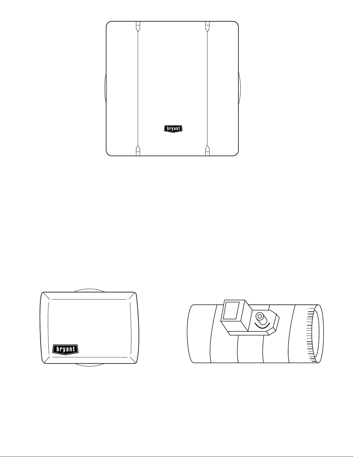
REMOTE SENSORS
Remote Sensors, shown in Fig. 3, are used to measure the
temperature in each zone. A Remote Sensor does not provide a
means to view or adjust the zone temperature; the User Interface
provides a means to view and adjust temperatures for all zones.
A98338
• Zone Perfect Plus installations must include a LAT (leaving
air temperature) sensor.
• If the installation includes a heat pump, an HPT (heat pump
temperature) sensor also must be installed.
•AnODT (outdoor temperature) sensor is optional in most
applications.
For more information about equipment sensors, see the section
"Components Required for Specific Applications."
E. Zone Dampers
Each zone must have at least 1 zone damper, shown in Fig. 4. If
more than 1 duct serves a single zone, up to 3 dampers may be
wired in parallel to a single output on the Equipment Controller.
Each zone damper is operated by an electric motor actuator, which
receives signals from the Equipment Controller. Dampers have 15
positions, ranging from fully closed to fully open. The position
selected for each damper at any given time is based on the relative
conditioning needs of each zone in the current mode.
A98339
Fig. 3—Remote Sensor
SMART SENSORS
The Smart Sensor measures and displays the temperature in the
zone. It also provides a means to adjust the temperature in that
zone only.
D. Equipment Sensors
The following equipment sensors are used in Zone Perfect Plus
installations:
—4—
A98340
Fig. 4—Zone Damper
PLUS
DESIGNING A ZONE PERFECT
INSTALLATION
The main objective when designing a zoning system is to maintain
at least the minimum airflow through the system when only 1 zone
requires conditioning, yet still provide sufficient airflow when all
zones require conditioning. The tasks described below provide
step-by-step instructions for designing an effective zoning system.
These tasks are grouped into the following phases:
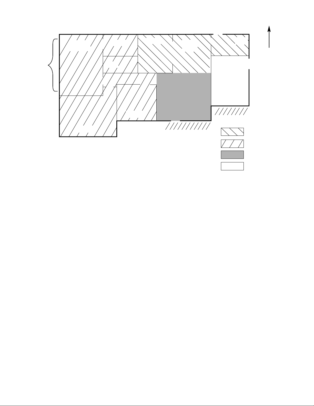
Page 5
N
Bath
Bath
Bedroom
Large
WIndow
Master
Bedroom
Bedroom
Fig. 5—Example of a Floor Plan
• Assigning Zones
Task 1—Assess the homeowner’s goals for comfort and energy
savings.
Task 2—Conduct a site survey and make preliminary zone
assignments.
• Sizing the Equipment
Task 3—Calculate block load estimates and zone load estimates.
Task 4—Size the heating and cooling equipment.
• Laying Out and Sizing the Duct System
Task 5—Choose register and return locations.
Task 6—Determine bypass needs.
Task 7—Lay out supply ducts and locate dampers.
Task 8—Determine appropriate damper and duct sizes.
• Laying Out Zone Components
Task 9—Choose locations for zone sensors.
A. Assigning Zones
TASK 1—ASSESS THE HOMEOWNER’S GOALS FOR
COMFORT AND ENERGY SAVINGS
For a zoning system to be successful, it must meet the homeowner’s goals for comfort and/or energy savings. Therefore, it is
essential to understand the homeowner’s goals before beginning to
design the system. In some situations, a homeowner’s expectations
might not be realistic and it would be impossible to design a
system to meet those expectations. By identifying this problem
from the start, you can help the homeowner revise these expectations and avoid creating a dissatisfied customer.
In addition to understanding the homeowner’s general goals for the
zoning system, you need to understand exactly how the home’s
occupants will use each room or area in the home. Use the
Homeowner Survey provided in the Appendix to help you gather
information from the homeowner.
TASK 2—CONDUCT A SITE SURVEY AND MAKE
PRELIMINARY ZONE ASSIGNMENTS
Conducting a Site Survey
The purpose of conducting a site survey is to gather the information that you need to:
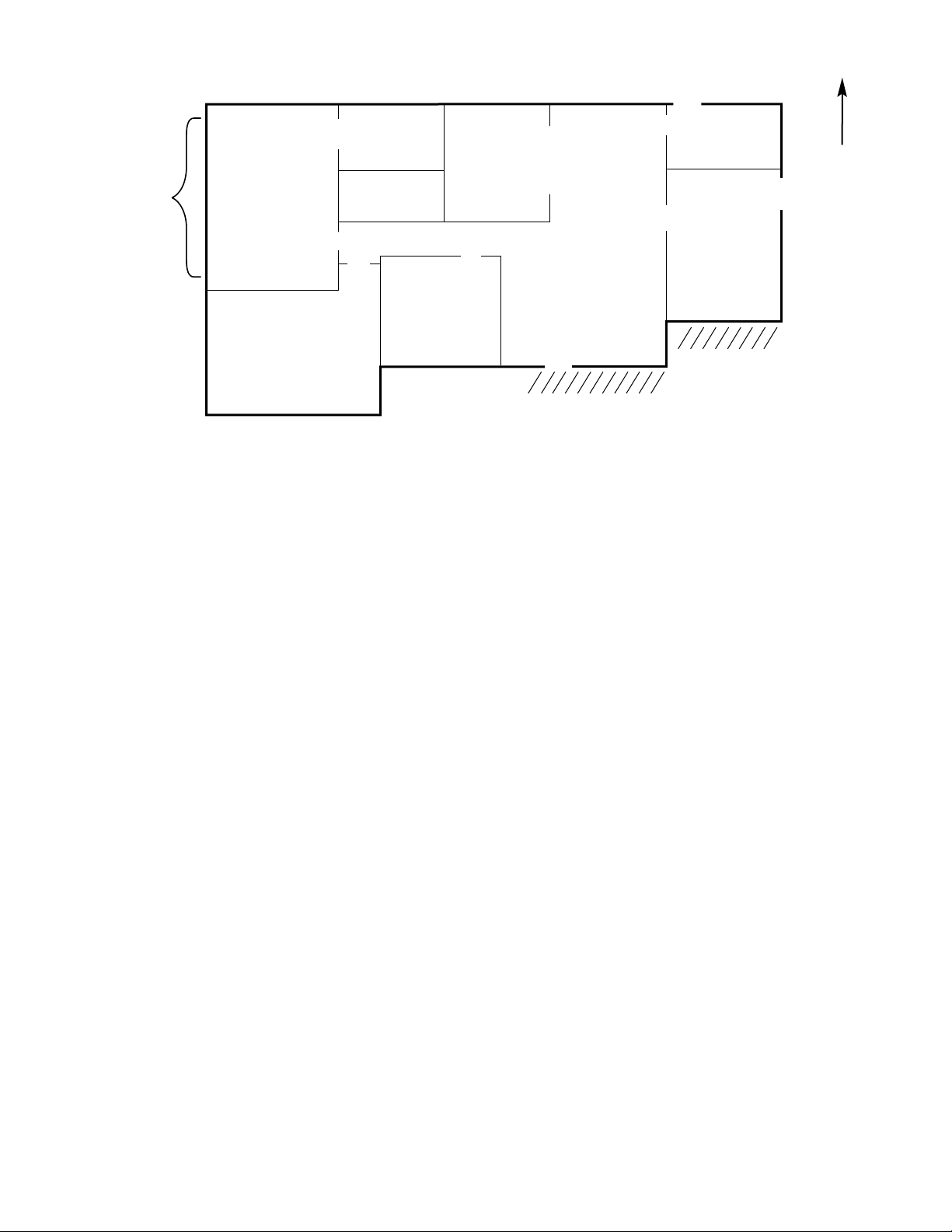
• Make zone assignments. Use the Floor Plan Worksheet
provided in the Appendix to draw a floor plan of the home.
Follow these guidelines:
Kitchen
Informal
Dining
Room
Living Room
Shaded
Family Room
Utility
Room
Shaded
— Provide the rough dimensions of each area or room.
— Indicate the location and relative size of doors, windows,
and skylights. In particular, identify any large glass areas
(exceeding 30 percent of the wall area).
— Indicate whether any trees or buildings cast shade on any of
the home’s exposures.
— Indicate the orientation of the home so you can determine
whether there are any rooms or areas facing south or west
where the solar heat load might be a factor when making zone
assignments.
Fig. 5 shows an example of a floor plan for a home, drawn as
part of a site survey.
• Calculate heating and cooling load estimates for the home
(Task 3). Gather the information required to use the method of
your choice for calculating these loads. If you have a worksheet
that you generally use to gather this information, feel free to
use it.
• Choose register and return locations (Task 5). Generally, the
Floor Plan Worksheet will provide sufficient information for
choosing register and return locations. In a retrofit installation,
indicate the location of existing duckwork, as well as heating
and cooling equipment.
• Lay out ducts and locate dampers (Task 6). Gather the
information about the home required to lay out ducts and locate
dampers using the method of your choice. If you have a
worksheet that you generally use to gather this information,
feel free to use it.
Making Preliminary Zone Assignments
The homeowner’s goals regarding comfort and energy savings
affect how many zones are appropriate for the system:
• In a system designed primarily for comfort, all zones usually
have comfort set points that remain relatively constant and that
have similar time schedules. Such a system may have a large
number of zones (5 to 8) of a relatively small size.
• In a system designed primarily for energy savings, there are
zones that are not used much of the time. Such a system must
have even larger ducts to guarantee proper airflow to the zones
that remain in use when some zones are unused. Such a system
generally must have a smaller number of zones of a relatively
larger size. In this case, you must be careful not to "over zone"
(assign too many zones).
When making zone assignments, use the information that you
gathered when conducting the site survey. Group areas that:
A98341
—5—
Page 6
N
Bath
Bath
Bedroom
Large
WIndow
Master
Bedroom
Bedroom
Fig. 6—Example of Zoning Assignments
• Are in use around the same time of day. For example, it often
makes sense to assign all bedrooms to a single zone because
they are occupied only during the night time when other rooms
in the home are not occupied.
• Have similar heating and cooling needs.
• Are physically separated from other areas.
• Are on the same level of the home. For example, the rooms on
the upstairs level often have a different heating or cooling
demand when compared to rooms downstairs. The differences
can be due to the tendency for heat to rise, different use of
occupancy, and the roof heat load.
• Have similar exposures to external heating gains and losses.
For example, it often makes sense to assign rooms with large
amounts of glass and western or southern exposure to the same
zone.
• The homeowner intends to "set back" at the same time.
• Let you avoid extremely small zones that would cause the
airflow through the unit to become extremely low when only 1
zone requires conditioning.
If possible, discuss these considerations with the homeowner. Get
the homeowner’s input before making initial zone assignments.
Mark your preliminary zone assignments on the Floor Plan
Worksheet provided in the Appendix. Fig. 6 shows an example of
zoning assignments marked on a floor plan worksheet.
At this point, consider your zone assignments to be preliminary.
The next task helps you check whether the zone assignments are
feasible.
B. Sizing the Equipment
TASK 3—CALCULATE BLOCK LOAD ESTIMATES AND
ZONE LOAD ESTIMATES
Using the information that you gathered in Task 2, calculate both
heating and cooling load estimates for the entire home. These
estimates are used primarily for sizing the heating and cooling
equipment for the system.
Kitchen
Shaded
Utility
Room
Zone 1
Zone 2
Zone 3
Zone 4
A98342
Informal
Dining
Room
Living Room
Shaded
Family Room
The standard Btu load calculations used for non-zoned systems
apply equally well to zoned systems. Use a reliable method with
which you are comfortable.
After you have tentatively defined the zones for a home, calculate
individual peak heating and cooling load estimates (in Btu’s) for
each of the zones. Use a reliable method with which you are
comfortable to calculate the peak zone load estimates. Refer to the
information that you gathered in Task 2.
The peak zone load estimates are used to determine whether the
zone assignments you have made make sense. They also are used
to size the zone dampers and ductwork.
When a zone is recovering from being set back, the system must
supply additional capacity beyond the zone’s losses to change the
temperature. The farther the desired setback, the more capacity
must be added.
For zones that will be set back and that need reliable recovery,
multiply their calculated zone loss by a recovery factor of 1.25.
Use the larger zone load estimate when determining the size of the
damper and duct required for the zone.
TASK 4—SIZE HEATING AND COOLING EQUIPMENT
Zone Perfect Plus is designed for use with a furnace or fan coil in
conjunction with a condensing unit or heat pump with a thermostatic expansion valve (TXV). Zone Perfect Plus operates within
an airflow range of 1.5 to 6 tons in the cooling mode.
How to determine the appropriate size of heating and cooling
equipment is a challenge that is subject to much debate. In a
residential zoning system, there is a very good possibility that a
system will use all zones on a given day. For that reason, we
recommend that you select the size of heating and air conditioning
units based on either the home’s block heating load or block
cooling load (whichever is greatest). Select the size of the air
handling unit based on the unit with the largest required CFM.
However, because the system has the capability to not condition
some zones at any given time, and because it is essential to
—6—
Page 7

maintain minimum airflow through the system at all times, it is
better to use slightly undersized equipment than slightly oversized
equipment in a zoning system.
Select heating and cooling equipment to meet the peak heating and
cooling block load estimates that you calculated in Task 3. Use the
Product Data Sheets for the equipment that you are considering to
determine whether the equipment can meet the system’s needs.
Verify that the selected indoor air handler can meet the heating and
cooling airflow requirements, as well as the system’s external
static pressure requirements.
NOTE: When you design the air distribution system, you need the
Product Data for the indoor air handler’s performance characteristics.
In a zoning system, it is especially important to select heating and
cooling equipment that is not too large. Equipment that is larger
than necessary compounds the problem of keeping the airflow in
the system above the minimum required by the equipment when
few zones require conditioning. Because the system shuts down
the equipment if the duct temperature falls outside the minimum or
maximum temperature limits, and limits the number of times the
equipment can restart to 4 times per hour, the actual capacity
provided by the system can be smaller with larger equipment.
To help avoid such problems, size the equipment based on the
calculated peak heating or cooling airflow (whichever is larger) of
the home. Do not add a fudge factor. Under even the heaviest
loads, the system has the capability to send its entire capacity to
less than the entire home. To redirect capacity where it is most
needed, the homeowner can easily set back some zones.
For information about the different types of heating and cooling
equipment that can be used with zoning systems, see the section
"Special Applications Using Zone Perfect Plus."
TASK 5—CHOOSE REGISTER AND RETURN
LOCATIONS
Determining the Number of Returns
Each zone should have a separate return with sufficient capacity to
return all of the air that is delivered to that zone. If you cannot
provide a separate return for a zone, use one of the following
methods to maintain airflow to that zone:
• Leave space under doors.
• Install grilles into or above doors.
• Provide a connection from the zone to another area that has an
adequate return.
When the air leaving a zone must pass into another zone, cross
conditioning occurs and it becomes difficult to maintain different
temperatures in the 2 zones. For this reason, a zone that is
significantly "set back" at times needs its own return.
Selecting Return Locations
The location of the returns for a zone significantly affects the
capacity that can be delivered to that zone. A high return removes
warmer air from the ceiling and a low return removes cooler air
from the floor. For a 2-story home, it is best to have both high and
low returns.
The location of the returns for a zone also has a significant effect
on the comfort in that zone. Because our feet are generally on the
floor and our heads are never closer than about 2 ft from the
ceiling. It is more important to keep the floor at a comfortable
temperature. In both cooling and heating, floors can become
uncomfortably cool and a low return can help alleviate this
problem.
In homes where the air handler is located in the basement, a return
near the basement floor will help avoid overcooling of the
basement. A low return also helps with the removal of dampness
and radon from the basement. However, a low return in the
basement lowers the return temperature cooling, increasing the
size of ducts required for proper operation of the system.
For homes with cathedral ceilings or multi-story rooms, a return at
the highest point can enhance both efficiency and comfort,
particularly during heating.
Selecting Register Locations
The general issues related to selecting register locations are the
same in zoned systems as they are in non-zoned systems. The only
exception is that the velocity of air leaving a register is likely to be
higher in a zoned system. Locate the register to take advantage of
the greater mixing of air that can be provided by the higher air
velocity and to minimize the discomfort caused downwind from
the register. As always, select register and return locations to avoid
stratification of air in the room and to maximize the mixing that
occurs when air swirls through a room.
Meeting Zoning Challenges in 2-Story Homes
In a 2-story home where cooling is the primary challenge, keep in
mind the principle of buoyancy—the tendency for cool air to sink
and warm air to rise. The lower level might tend to be over
conditioned or the upper level might tend to be under conditioned.
To help avoid such problems, on the upper level you can:
• Use high registers to mix the cooled air with the warm air near
the ceiling.
• For registers, direct or deflect the air upward and maintain high
grille velocity.
• Install returns near the ceiling.
• Close doors to rooms and minimize space below doors when
possible, but only if each room has its own return.
• Install a ceiling fan in each room.
Recording Return and Register Locations
You can mark the locations for returns and registers on the Floor
Plan Worksheet for the home. Indicate the approximate height of
each return and register.
TASK 6—DETERMINE BYPASS NEEDS
Bypass dampers have become a standard component in many
zoning systems produced today. When multi-stage equipment with
an ICM blower motor is used in a properly sized duct system, a
bypass is not always necessary.
The use of a bypass to add load to a system is most common in
commercial applications. In residential applications, a direct bypass is most common. Without proper precautions, the use of a
direct bypass can lead to poor comfort and/or equipment failure.
A direct bypass recycles either the coldest or hottest air in the
system back into the return air inlet when it is needed the least. In
cooling, the direct bypass can cause the coil to freeze and the
equipment to shut down due to the low temperature limit. In
heating, the direct bypass can cause overheating and the equipment
to shut down due to the high temperature limit. Either of these
situations reduces the comfort that the system can provide.
A direct bypass with Zone Perfect Plus using the out zone feature
is an excellent option. The bypass reduces air noise under
minimum load and the out zone feature keeps the equipment from
shutting down.
TASK 7—LAY OUT SUPPLY DUCTS AND
LOCATE DAMPERS
The supply air duct system for a zoning system has a different
layout than one designed for a conventional single zone system.
Provide a separate zone duct to carry all of the air for each zone.
The zone damper for each zone is located in its zone duct. Branch
ducts connect to each zone duct, downstream from the zone
damper. They supply conditioned air to individual rooms or areas
in the zone.
In some systems, it might not be convenient to connect all of the
branch ducts for a zone to a single zone damper. In such a case,
multiple branch ducts can be fed through multiple (up to 3) zone
dampers. All of the zone dampers for the zone are wired in parallel
so that they open and close the same amount at the same time.
—7—
Page 8

N
Bath
Bath
Bedroom
Large
WIndow
Master
Bedroom
Bedroom
Zone Damper
Fig. 7—Example of Supply Duct Layout and Damper Locations
You can mark the supply duct layout and damper location on the
Floor Plan Worksheet for the home. Fig. 7 shows an example of
supply duct layout and damper locations marked on a floor plan
worksheet.
TASK 8—DETERMINE APPROPRIATE DAMPER AND
DUCT SIZES
Airflow is the way that a zoning system moves heating or cooling
Btu’s to the load (the demand for heating or cooling in the home)
and back to the heating or cooling equipment. For the equipment
to perform properly, the system must maintain a minimum load on
the equipment. In a residential system, the necessary airflow
usually is measured in cubic feet per minute (CFM) exiting the
duct system. For most zoning systems, the system must maintain a
minimum of 300 CFM per ton exiting the duct system (not
recirculated).
A zoning system distributes air based on the differing load in each
zone. Most of the time, some of the dampers are partially closed;
some dampers may be completely closed. By using a larger duct
size for a zoning system that you would use in a non-zoned system,
you help assure that air flows at an appropriate velocity where it is
needed and that the sound level remains acceptable.
Because Zone Perfect Plus controls airflow based on the proportional needs of each zone, the logic used for selecting appropriate
damper and duct sizes is different than the logic you would use for
other zoning systems or a non-zoned system. It is not reasonable to
attempt to design an air distribution system that can handle 100
percent of the system’s airflow capacity through 1 zone. However,
it is reasonable to design the air distribution system to be able to
move the minimum airflow with one-third of the zones’ dampers
fully open.
NOTE: The use of multi-stage heating and/or cooling equipment
can significantly reduce the size of dampers and ducts required for
an installation. For more information, see the section "Using
Multi-Stage Equipment with Zoning."
Determining Duct Size Based on Damper Size
Kitchen
Informal
Dining
Room
Living Room
Shaded
Unit in
Basement
Family Room
Shaded
Utility
Room
Zone 1
Zone 2
Zone 3
Zone 4
A98343
The most logical way to determine the damper and duct size
requirements for a zoning system is to first determine the zone duct
size required for each zone. Select the damper size that will move
500 CFM per ton at the desired velocity as you normally would.
Do not undersize these dampers! Then, size ducts based on 500
CFM per ton of load to each zone. Zone ducts should always be as
large or larger than the selected damper.
NOTE: For zones that need quiet operation and fast setback
recovery, use 600 CFM per ton to size zone dampers and ducts.
Larger ducts are always better with an ICM blower system. With
a non-ICM blower in the system and excessively large ducts, one
or both of the following problems might occur:
• Humidity removal might suffer.
• Register "throw" might be reduced. Continuous fan use and
good register and return placement can solve this problem.
The combination of larger ducts and an ICM blower eliminates
many problems that can occur in a zoning installation.
It is wise to oversize the ducts for small zones so that the heating
and cooling equipment can continue to operate when only the
small zones need conditioning. The zoning system will maintain
proper temperature control even if the ducts are oversized.
When determining the duct size for a zoned system, keep in mind
that duct balancing, which is an important concept for designing
non-zoned systems, is not necessary in a zoned system. The zoning
system itself will balance the ducts.
Why Oversized Ducts Are Not a Problem
with Zone Perfect Plus
Example 1: When the air handling equipment is used on a system
with oversized ducts, it delivers less air through the ductwork. This
reduction in volume and velocity can cause conditioned air to
stratify and not reach the zone sensor in a zone. When this situation
occurs, the system assumes there is a greater demand in that zone
and opens the zone damper to increase airflow to that zone.
—8—
Page 9

User Interface
N
Large
WIndow
Master
Bedroom
Bedroom
Zone Damper
Fig. 8—Example of Zone Sensor Locations
Bath
Bath
X
Kitchen
X
Bedroom
= Zone Sensor Locations
X
Informal
Dining
Room
Living Room
Shaded
Basement
X
X
Unit in
Family Room
Shaded
Utility
Room
Zone 1
Zone 2
Zone 3
Zone 4
A98344
Example 2: In a 2-stage system the unit starts in low speed, the
system reacts the same as in Example 1 except, when more zones
demand conditioning and other zone dampers open, the system
switches the equipment to 2-stage mode, increasing the system
capacity and the airflow to the zones requiring conditioning.
TASK 9—CHOOSE LOCATIONS FOR ZONE SENSORS
One zone sensor is required for each zone. Generally, the User
Interface’s internal sensor serves as the zone sensor for its zone
(Zone 1). A Smart Sensor or Remote Sensor may be used in any
zone, except a Smart Sensor may not be used in Zone 1.
For proper operation of the Zone Perfect Plus system, each sensor
must accurately measure the temperature within its zone. Considerations for selecting a location for a sensor are essentially the
same as the considerations for selecting a location for any
thermostat.
When selecting a location for a sensor, follow these guidelines:
• Select a location close to the center of the sensor’s zone, on an
inside wall. In particular, avoid locations where the air from
another zone mixes with the air in the zone you are trying to
monitor. If the target temperatures for the 2 zones are different,
the system might not be able to determine the necessary amount
of conditioning to supply to each zone.
• Plan to mount the sensor approximately 5 ft (1.5 m) above the
floor.
• Select a section of wall without pipes or ductwork.
• If there are 2 or 3 bedrooms in a single zone, locate the sensor
in the hallway connecting the bedrooms, near the return grille
but not directly in the return airflow.
•Donot select a location:
— on an outside wall, close to a window, or next to a door
leading outside.
— exposed to direct light and heat from a lamp, the sun, a
fireplace, or any other heat-radiating object that might cause a
false reading.
— in direct airflow from supply registers and return grilles.
— in areas with poor circulation, such as behind a door or in an
alcove.
You can mark the locations for zone sensors on the Floor Plan
Worksheet for the home. Fig. 8 shows an example of zone sensor
locations marked on a floor plan worksheet.
C. Considerations When Retrofitting
an Installation
It is a far greater challenge to design a retrofitted zoning system
than it is to design a system for a new home. For a zoning system
to operate properly in a retrofitted installation, it usually is
necessary to use 1 or more of the following approaches to
compensate for an air distribution system that is too small for the
zoning system:
• Modify the existing ductwork and dampers to handle additional
airflow.
• Set mechanical minimum damper positions in some zones.
• Improve the home’s insulation to reduce the home’s demand
for heating and cooling (load) so that lower capacity equipment
can be used effectively in the installation.
• Use multi-stage heating and cooling equipment so the equipment capacity can match the load when only a limited number
of zones require conditioning.
• Select an air handler that is designed to overcome the high
static pressure in the ductwork and force more air through the
system. A unit with an ICM blower is a good choice.
When selecting the appropriate approach for a retrofitted system,
be sure to inform the homeowner of the tradeoffs between cost and
comfort when comparing approaches.
D. Installing the System
To install each component, follow the Zone Perfect Plus Installation Instructions provided with the Zone Perfect Plus kit and the
—9—
Page 10

Installation Instructions provided by Bryant with the selected
heating and cooling equipment. Thoroughly test the installation,
following the instructions provided, to ensure that it is installed
and set up properly.
COMPONENTS REQUIRED FOR SPECIFIC
APPLICATIONS
The following components are required in all Zone Perfect Plus
installations:
• a TXV (thermostatic expansion valve)
• a LAT (leaving air temperature) sensor, provided with all Zone
Perfect Plus kits
In a heat pump installation (not a dual fuel application), an HPT
(heat pump temperature) sensor is required.
In a dual fuel application, or any installation using the low
temperature lockout feature, the auxiliary heat lockout feature,
and/or the automatic humidity level adjustment feature, an ODT
(outdoor temperature) sensor is required. In other Zone Perfect
Plus applications, this sensor is optional.
Information about each of these components is provided in the
following sections.
A. Thermostatic Expansion Valve
A TXV is required in all Zone Perfect Plus installations. The
TXV replaces the fixed metering orifice, which regulates the
amount of liquid refrigerant entering the indoor evaporator. The
TXV assures that no liquid refrigerant leaves the evaporator,
possibly returning to the compressor and causing damage.
The likelihood of incomplete refrigerant evaporation is much
greater in a zoning system than in a non-zoned system because of
the reduced airflow when only a few zones require conditioning.
Thus, the TXV protects the compressor from possible damage
when airflow is very low.
NOTE: The purpose of the TXV is not to protect the coil from
freezing. The leaving air temperature (LAT) sensor performs this
function.
B. Leaving Air Temperature Sensor
A LAT sensor is required for all types of equipment. When
used with fossil fueled furnaces and air conditioned systems, locate
the LAT sensor in the air supply duct downstream of the furnace
and cooling coil. The LAT sensor must be upstream of the bypass
damper, if one is included in the system, or the first zone damper.
The LAT sensor monitors the leaving air temperature during both
heating and cooling. The User Interface is programmed with
temperature limits and prevents equipment operation if the leaving
air temperature exceeds the upper limit during heating or falls
below the lower limit during cooling.
When used with a heat pump, locate the LAT sensor downstream
of the accessory electric heaters. The LAT sensor monitors the air
temperature leaving the accessory electric heaters during heating,
as well as the temperature leaving the indoor coil during cooling.
C. Heat Pump Temperature Sensor
An HPT sensor is required in a heat pump installation, unless it is
a dual fuel application. Locate the HPT sensor in the air stream
between the indoor coil and the accessory heaters.
This sensor serves a similiar purpose to the LAT sensor, but does
not sense the temperature of the air leaving the electric heaters.
The HPT sensor monitors the air temperature leaving the indoor
coil during heating by the heat pump, and prevents the operation of
the heat pump if the leaving air temperature exceeds the fixed
temperature limit of 115°F.
D. Outdoor Temperature Sensor
An ODT sensor is required in all dual fuel applications. An ODT
sensor also is required to use the low temperature lockout feature,
the auxiliary heat lockout feature, and/or the automatic humidity
level adjustment feature in any installation.
For dual fuel systems, this sensor is used to control the switch from
electric to fossil fuel operation when the outdoor temperature
reaches the preset temperature. When used with the low temperature lockout feature, the ODT sensor is used to prevent equipment
operation during cooling when the outdoor temperature falls below
the preset lower limit.
When used with the auxiliary heat lockout feature, the ODT sensor
is used to prevent electric heat operation in a heat pump installation when the outdoor temperature rises above the preset limit.
When used with the automatic humidity level adjustment feature
during heating, the system automatically reduces the humidity set
point by 1 percent for every 2°F reduction in outdoor temperature.
In other Zone Perfect Plus applications, this sensor is optional.
SPECIAL APPLICATIONS USING ZONE PERFECT
This section discusses special Zone Perfect Plus applications that:
• Emphasize energy savings or "setback."
• Include multi-stage equipment.
• Include variable-speed blowers.
• Include a barometric bypass damper.
A. Understanding the Requirements of Setback with
Zoning
If you are designing a zoning system for energy savings, it is
important to understand the additional challenges that you face
before you begin to design the air distribution system. The energy
savings achieved by setting zone temperatures back (lower for
heating or higher for cooling) can be substantial. However,
"setback" brings additional requirements to the system.
The zones that are not set back might be surrounded by zones that
are. This situation results in the need to deliver additional capacity
to the zone that is not set back since the zone duct and damper need
to deliver the capacity required to meet the zone’s needs and to
compensate for the conditioning that spills over to the neighboring
zones that are set back.
Thus, the effective block load of any zone increases above the
value normally calculated for it when its neighboring zones are set
back. The amount of the increased load depends on the extent to
which the neighboring zones are set back. This need for additional
capacity increases the size of damper and duct required for the
zone.
When a zone has been set back, the system eventually must return
the zone to a more comfortable conditioning level. This need
increases the capacity that must be delivered to the zone. The
amount of additional capacity that is necessary is the capacity
required to match the zone’s load plus the capacity required to
implement recovery within a reasonable time period. The amount
of capacity required for recovery depends on the extent to which
the zone had been set back and the desired recovery time. Again,
this need for additional capacity increases the size of damper and
duct required for the zone.
The improved insulation found in today’s homes compounds the
demands imposed by setback. The better insulated the home, the
smaller the size of heating and cooling equipment required for the
home. However, the requirements of setback recovery are determined by the heat capacity of the zone, not by its losses, and heat
capacity is not changed by insulation. Improved insulation also
increases the challenge of maintaining different temperatures
between zones since the interior walls appear more transparent to
heat flow when the outer walls are better insulated. The opportunity for energy savings in addition to the savings already achieved
through better insulation is reduced in a well insulated home.
B. Using Multi-Stage Equipment with Zoning
When dampers are closed in some zones and the air distribution
system becomes effectively smaller in a system with single-stage
equipment, airflow may drop below the system’s minimum,
causing the equipment to shut down. In this situation, it is difficult
to maintain comfort in the home due to excessive equipment
cycling.
PLUS
—10—
Page 11

In contrast, multi-stage equipment shifts to low-stage operation
(typically 60 percent of total capacity) when the air distribution
system becomes effectively smaller. Because the equipment reduces its minimum airflow limit, it is able to continue to operate.
The reduced capacity generally is adequate to supply the necessary
conditioning since only 1 or 2 zones need conditioning under these
circumstances.
The following multi-stage equipment can be used with the zoning
system:
• Two-speed air conditioners.
• Two-speed heat pumps.
• Two-stage furnaces.
• Two-stage electric heat used without a heat pump.
NOTE: When using multi-stage heating or cooling equipment
with Zone Perfect Plus, the zoning system must be allowed to
control the equipment staging. Therefore, there must be separate
inputs for low-stage and high-stage operation, and the equipment
must be configured to operate from these inputs only. Outdoor
temperature switches, staging algorithms, and so forth should not
be used.
C. Using Variable-Speed Blowers with Zoning
PSC blowers are single-speed blowers. A PSC blower runs at a
fixed speed and cannot change speed as the dampers move. A PSC
blower usually can produce about 0.5 in. of static pressure.
In contrast, ICM blowers are variable-speed blowers. Air handlers
using ICM blowers are designed to supply a fixed quantity of air
into a duct system regardless of the external static pressure. The air
handler can "sense" the external static pressure and change the
motor speed to deliver the desired airflow. An ICM blower
typically can produce about 0.9 in. of static pressure.
In a properly-designed system, the use of an ICM blower can help
assure adequate airflow through the system regardless of damper
positions. Air handlers using ICM blowers typically are programmed to produce 325 CFM per ton (of equipment capability).
The use of such an air handler does not reduce the damper or duct
size requirements of a system, but does help the system run
properly and quietly without a bypass.
D. Bypassing with Zoning
When only 1 zone requires conditioning, airflow through the
ductwork can fall below the system’s minimum requirements. This
situation can cause problems for the system’s equipment and can
lead to discomfort for the home’s occupants.
There are 3 standard methods that have been developed to
maintain minimum airflow, reduce duct velocity, and reduce duct
noise:
• Bypass air to an unconditioned space.
• Bypass air to a conditioned space.
• Bypass air directly to the return.
The term "bypass" means to allow additional air through the
system that bypasses the zone dampers, the zones, or both. The 3
methods described above use a bypass damper, which receives air
from the supply plenum. A barometric damper, which opens when
the supply air pressure reaches a preset value, generally is used for
the bypass. Thus, the barometric bypass damper acts as a pressure
regulator, releasing enough air to reduce the supply plenum
pressure to an appropriate level.
In addition to the 3 standard bypass methods, Zone Perfect Plus
provides an additional bypassing method—OUT zones. OUT
zones can serve as an excellent bypassing method. You can think
of an OUT zone as a temporary dump zone. Ideally, an OUT zone
should be available in the system at all times.
Each of the conventional bypass methods, as well as bypassing
using OUT zones, is discussed in the sections below. As you
evaluate the usefulness of these methods for a particular installation, keep in mind that bypassing using OUT zones can work well
in conjunction with a barometric bypass.
NOTE: A bypass damper reduces air noise by reducing airflow
velocity in the ducts. A direct bypass to the return does not add
load to the system.
BYPASSING TO AN UNCONDITIONED SPACE
Conditioned air can be bypassed to an unconditioned space. This
type of bypass is considered an indirect bypass.
Although there is no limit on the amount of air that can be
bypassed using this method, this type of bypass wastes energy. In
addition, this method creates negative indoor pressure, which pulls
unconditioned air into the home. This method is rarely used in
zoning installations and we do not recommend it.
BYPASSING TO A CONDITIONED SPACE
Conditioned air also can be bypassed to a conditioned space, called
a dump zone. This type of bypass also is considered an indirect
bypass.
Although there is no limit on the amount of air that can be
bypassed using this method, this type of bypass reduces the
effectiveness of the zoning system. The dump zone tends to be
over conditioned and uncomfortable.
This method is acceptable if you have a zone that can function as
a dump zone, such as a large basement. However, there rarely is a
zone suitable for this use.
BYPASSING DIRECTLY TO THE AIR RETURN
There are advantages and disadvantages to bypassing directly to
the air return using a barometric damper. The advantages of a
direct barometric bypass include:
• A direct bypass serves as a pressure regulator, bypassing
enough air to hold the static pressure in the plenum to a safe
level. Thus, a direct bypass prevents excessive air velocities,
which can cause noise and drafts.
• Because a direct bypass returns conditioned air back into the air
handler, it makes the leaving air colder in cooling and warmer
in heating. A direct bypass increases the Btu content of the air
entering the duct system while airflow (CFM) remains at the
same level. The result is that more capacity can be forced into
the system without increasing the airflow.
• During cooling, the process of making the leaving air colder
removes more water from the air. When a system is bypassing
a large amount of air (only a small portion of the zones require
conditioning), there is relatively little total demand on the
system. During such periods of light load, humidity often can
be a problem. The direct bypass automatically increases the
removal of water when it is most needed.
The disadvantages of a direct barometric bypass include:
• It is very difficult, if not impossible, to determine how much air
is being bypassed under a given condition. Traditional calculation methods can assure that the bypass is large enough, but
do not prevent the bypass from becoming too large. The
amount of air that can be bypassed often is greater than the
amount that the equipment can tolerate.
NOTE: The dimensions and attachment points of the bypass
ductwork have more influence on the amount of air that is
bypassed than the ratings of the bypass damper.
• Airflow into the ductwork might be reduced excessively,
resulting in insufficient conditioning.
• Because too much air can be bypassed, entering and leaving air
temperatures can range outside safe values for the heating and
cooling equipment, possibly resulting in equipment failures or
shortened equipment life. A direct bypass, unlike an indirect
bypass, does not remove Btu’s from the equipment, although it
does allow more airflow through the equipment.
Although it is commonly believed that the equipment is
protected as long as proper airflow is maintained, this belief is
true for an indirect bypass but not for a direct bypass. A direct
—11—
Page 12

bypass provides no protection for the equipment even though it
increases the airflow through it. Particularly for furnaces, a
direct bypass can harm rather than help by overheating internal
components. Therefore, the amount of air bypassed during
heating with a direct bypass must be limited.
• If bypassing results in excessive temperature in the supply duct
and a limit is tripped, the equipment shuts down. To protect the
equipment, the zoning system does not allow the equipment to
be turned on more than 4 times per hour. If the limit is tripped
repeatedly, the amount of heating or cooling delivered to the
zones might decrease dramatically. Thus, a direct bypass might
initially help the performance of a system during a period of
limited demand, but it might eventually result in an abrupt loss
of conditioning.
NOTE: A leaving air temperature (LAT) sensor is required in
every Zone Perfect Plus system. If the system is programmed
properly, this sensor ensures that the equipment turns off when the
leaving air temperature exceeds a safe range. Although it might be
tempting to omit the LAT sensor to increase the system’s performance, you risk eventual equipment failure. The equipment’s
internal limits are not intended to be tripped repeatedly.
Similarly, if the LAT range is not programmed properly, you can
cause the equipment’s internal limits to trip repeatedly. Again, you
risk eventual equipment failure.
BYPASSING USING OUT ZONES
Although the OUT zone feature can be used to provide energy
savings to the homeowner, its primary use is to give the system a
place to direct excess airflow to avoid tripping limits that protect
the heating or cooling equipment when the airflow falls below the
minimum required to operate safely. By closing an OUT zone’s
damper(s) if the zone becomes cooler than the coolest zone (in
cooling) or warmer than the warmest zone (in heating), the system
avoids over conditioning the OUT zone. Thus, using OUT zones
for bypassing provides the advantages of bypassing to a dump
zone, but avoids the disadvantages.
The following scenario illustrates bypassing in a system that has
both a direct barometric bypass damper and several OUT zones.
This example illustrates the operation of the system in the cooling
mode. Keep in mind that the system would operate similarly in the
heating mode.
Imagine a zoning system is running in cooling mode and less than
1/3 of the zones have a cooling demand. The air pressure in the
ducts starts to build and the barometric bypass damper starts to
open. As the air recirculates to the return of the air handler and into
the evaporator coil, the leaving air temperature drops.
When the leaving air temperature, as measured by the leaving air
temperature (LAT) sensor, falls to 46°F, the system opens all OUT
zone dampers 3 positions. This action relieves the duct pressure
and may allow the bypass to close. If the temperature drops
another degree, the OUT zone dampers open another 3 positions.
The system continues to progressively open the OUT zone
dampers as the temperature falls until 1 of the following events
occurs:
• The leaving air temperature stabilizes and the OUT zone
dampers maintain position. (This result is the most common.)
• The demand is met for all zones and the system shuts down.
• The OUT zone dampers are fully open (position 15).
• The OUT zones become colder than the lowest cooling system
set point and their dampers close.
• In extreme cases, the leaving air temperature can fall to 40°F.
Usually this situation is caused by factors outside the heating
and cooling system, such as doors and windows left open when
the rest of the home is satisfied. In this extreme case, the limit
for the system is reached and the system shuts down the cooling
equipment.
GLOSSARY
Barometric Bypass Damper
Device used to control noise and maintain airflow in a heating or
cooling system during minimum airflow. When the supply airflow
reaches a preset value, the barometric bypass damper opens.
Block Load
Heating or cooling load of the home as 1 space.
Btu
British thermal unit. A standard unit of heat—the amount of heat
required to raise the temperature of 1 lb of water 1°F.
Bypass
Configuration that allows additional air through the system that
bypasses the zone dampers, the zones, or both.
Cooling Demand
The difference between the current temperature in a zone and the
zone’s cooling set point (when the temperature is higher than the
cooling set point).
Condition
Process of ventilating, heating, or cooling (and sometimes humidifying or dehumidifying) an area.
Dump Zone
Conditioned zone to which air is bypassed.
Equipment Controller
Device that interfaces with the home’s heating and cooling
equipment so Zone Perfect Plus can control that equipment.
External Static Pressure
Measured static in inches wc from the inlet to the outlet of the air
handling unit.
Heat Pump Temperature (HPT) Sensor
Device that measures the temperature of air leaving the indoor coil.
Zone Perfect Plus uses this temperature under certain circumstances to adjust the operation of the heating or cooling system.
Heating Demand
The difference between the current temperature in a zone and the
heating set point (when the temperature is lower than the heating
set point.)
ICM (Integral Control Motor) Blower
Variable-speed blower. Air handlers using ICM blowers are
designed to supply a fixed quantity of air into a duct system
regardless of the external static pressure.
Leaving Air Temperature (LAT) Sensor
Device that measures the temperature of air leaving the air handler
in heating or cooling. Zone Perfect Plus uses this temperature
under certain circumstances to adjust the operation of the heating
or cooling system.
Multi-Stage Equipment
Heating or cooling equipment that can adjust the capacity in
response to the demand of the zoning system.
OUT Zones
Zones (usually unoccupied) that have been selected to receive no
conditioning for a period of time unless the temperature exceeds
85°F or falls below 60°F. Zone Perfect Plus also uses OUT zones
to relieve the heating or cooling equipment under overload
conditions.
Outdoor Temperature (ODT) Sensor
Device that measures the temperature of the air outside. Zone
Perfect Plus uses this temperature under certain circumstances to
adjust the operation of the heating or cooling system.
PSC (Permanent Split Capacitor) Blower
Single-speed blower. A PSC blower runs at a fixed speed and
cannot change speed as the dampers move.
—12—
Page 13

Remote Sensor
Device that measures the temperature in a zone, but does not
provide a means to view or adjust the temperature.
Set Points
Temperatures selected to determine the acceptable temperature
range for each zone. The zone’s higher set point determines when
the zone needs to be cooled. The zone’s lower set point determines
when the zone needs to be heated.
Set Back
Process of significantly reducing the set point of a zone during
heating or increasing the set point of a zone during cooling to
reduce the amount of conditioning required in the zone.
Smart Sensor
Device that measures the temperature in a zone, and that provides
a means to view and adjust the temperature in that zone.
Thermostatic Expansion Valve (TXV)
Device that senses both the pressure and temperature at the outlet
of the evaporator, and adjusts the refrigerant flow into the
evaporator. The TXV ensures that no liquid refrigerant leaves the
evaporator, possibly returning to the compressor and causing
damage.
Ton
Measurement of heating or cooling equipment capacity equivalent
to 12,000 Btu’s per hour.
User Interface
Command center of Zone Perfect Plus. Includes displays and
buttons that let the homeowner select features and see information
about the system.
Zone
Distinct area within a building where the airflow is controlled by
a zone damper.
Zone Damper
Motorized air volume control damper, which regulates the flow of
conditioned air into the zone.
Zone Duct
The main air supply duct to a zone, which carries all of the air and
contains the Zone Damper for the zone.
Zone Load
Heating or cooling load of a single zone.
Zoning System
Equipment that allows cooling and/or heating equipment to regulate the temperature independently in different areas of a home.
APPENDIX—WORKSHEETS
This appendix provides the following worksheets for you to copy
and use when designing a Zone Perfect Plus installation:
• Zoning Design Checklist
• Homeowner Survey
• Floor Plan Worksheet
—13—
Page 14

A. Zoning Design Checklist
Use this checklist to make sure that you have completed each necessary task when designing a Zone Perfect Plus installation.
Assigning Zones
[] Task 1—Assess the homeowner’s goals for comfort and energy savings.
[] Task 2—Conduct a site survey and make preliminary zone assignments.
Sizing the Equipment
[] Task 3—Calculate block load estimates and zone load estimates.
[] Task 4—Size the heating and cooling equipment.
Laying Out and Sizing the Duct System
[] Task 5—Determine bypass needs.
[] Task 6—Choose register and return locations.
[] Task 7—Lay out supply ducts and locate dampers.
[] Task 8—Determine appropriate damper and duct sizes.
Laying Out Zone Components
[] Task 9—Choose locations for zone sensors.
—14—
Page 15

Homeowner Survey
1. How many members are there in your household?
2. Describe the activities in your household on an unusual day. In particular, are
there activities that might require extra cooling or heating?
3. Describe the typical usage of the various areas of your home throughout the day.
4. What areas, if any, in your home that are used infrequently, such as a formal dining
room, or that are unoccupied for large periods of time during the day or night?
5. What areas, if any, in your home that are closed off from the rest of the house
(for example, a room where you always keep the door closed?)
6. Is there an area in your home that will be used for exercise?
7. Describe the entertaining that you do in your home:
How often do you entertain in the summer? In the winter?
During what times of the day do you typically entertain?
How many people do you usually entertain?
What areas of your home do you use when you entertain?
Are there times when people go in and out of the house frequently (for example,
if you entertain outdoors)?
—15—
A98345
Page 16

8. What temperature do you normally want to maintain in your home during the day
in the summer? The night in the summer? The day in the winter? The night in the
winter?
9. Are there any times when you want significantly different temperatures in all or
part of your home? If so, in what areas or rooms? How quickly do you want the
temperature change to occur?
10. To what extent do you want to be able to control the temperature in your home?
11. What do you expect from your indoor comfort system?
Additional Questions for an Existing Home
1. Are there any areas or rooms in your home that are too hot or cold in the winter?
In the summer?
2. Do you have a humidity problem in your home? Too much? Too little?
3. How long do you plan to live in your present home?
4. What do you like about your present heating and cooling system? What do you
dislike?
A98346
—16—
Page 17

Floor Plan Worksheet
—17—
A98347
Page 18

© 1998 Bryant Heating & Cooling Systems 7310 W. Morris St. Indianapolis, IN 46231
—18—
Printed in U.S.A. ap172 Catalog No. BY-809-650
 Loading...