

Page 1

Zoning Design Guide
ZONE PERFECT PLUS
Cancels: AP17–2 AP17–5
8-00
NOTE: Read the entire instruction manual before starting the
installation.
TABLE OF CONTENTS
INTRODUCTION..........................................................................1
OVERVIEW OF ZONING............................................................1
WHAT IS ZONING?.....................................................................1
IS A ZONING SYSTEM RIGHT FOR THIS JOB?....................1
DESIGNING A ZONE PERFECT PLUS INSTALLATION......1
ASSIGNING ZONES...............................................................2
SIZING THE EQUIPMENT....................................................3
SIZING THE DUCT SYSTEM ...............................................3
REFERENCE FOR DUCT SIZING WORKSHEET:
STEP 6......................................................................................4
REFERENCE FOR DUCT SIZING WORKSHEET:
STEP 7......................................................................................5
APPENDIX ....................................................................................5
INTRODUCTION
Zone Perfect Plus is a zoning system capable of providing zone
control requirements for 2, 4, or 8 living or business areas. This
system allows the home or business owner to control the living
environment in an individualized way. The Zone Perfect Plus kit
includes the User Interface, Equipment Controller, Remote Sensors, an Outdoor Temperature Sensor, and Leaving Air Temperature (LAT) Sensor. See Fig. 1 for components which make up an
8–zone kit.
This guide provides information to help you design a Zone Perfect
Plus installation. It discusses general topics related to designing a
zoning control system.
Use this guide to help you design a zoning system that will:
• Meet or exceed the expectations regarding the system’s capabilities. This goal will result in improved customer perception
of your company, as well as repeat business and referrals.
• Protect the heating and cooling equipment used in the system.
This goal will result in improved system reliability, longer life
of heating and cooling equipment, and reduced warranty costs.
To design a zoning system to perform well under all conditions, it
is essential to viewthe systemas awhole atthe designstage, rather
than to begin selecting and installing individual components
without a careful assessment of how they will work together. Be
sure to perform all of the Tasks described in this guide before you
begin to install components.
OVERVIEW OF ZONING
Zoning systems bring the possibility of total comfort control to the
occupants by providing the right amount of heating or cooling to
each space. Comfort can be described as the absence of sensation.
Ideally, a zoning system should keep the occupants of the space
comfortable without them being aware of the system.
WHAT IS ZONING?
A zone is a conditioned space (one room or a group of rooms) that
is separately controlled by its own sensor. There are as many
sensors in a designed system as there are zones.
A zoning system is a heating and cooling control system that
maintains each zone at a predetermined temperature set point and
maintains the overall space at a predetermined humidity set point.
In addition to meeting these basic goals, Zone Perfect Plus is
designed to:
• Direct conditioned air proportionately based on the needs of
each zone, so that the zone(s) with the greatest demand receive
relatively more conditioned air.
• Keep the sound produced by the system low enough that
occupants will not find it objectionable.
• Conveniently interface with and protect the system’s heating
and cooling equipment.
• Maintain at least the minimum airflow necessary to keep
heating and cooling equipment running efficiently.
IS A ZONING SYSTEM RIGHT FOR THIS JOB?
When designing a zoning system, it is important to keep in mind
what a zoning system can and can not do. A zoning system is only
part of a complete heating and cooling system. A properly selected
heating and cooling system has a limited heating and cooling
capacity. A zoning systemmay ormay notincrease theeffective
capacity. This depends on whetherthe system isbeing designed
for comfort (no increase) or energy savings (some increase in
overall effective system capacity).
A zoning system reduces the effective size of the air distribution
system as dampers are adjusted and closed to meet the needs of the
zone. The primary challenge when designing a zoning system is to
make sure that the air distribution system cannot become so
effectively small that the reduction in airflow causes one of the
following problems:
• Air noise or draft becomes excessive.
• The heating or cooling equipment is shut down because
temperature limits are exceeded.
• The life of the equipment is reduced because of stresses related
to excess temperatures.
The addition of a zoning system will not correct undersized
duct problems. A zoning system will compensate for oversized
ducts, but might make a bad situation worse in the case of
undersized ducts. There are many ways to make a marginal duct
system perform better. Most of these approaches involve changing
ducts, registers, and/or heating or cooling equipment.
DESIGNING A ZONE PERFECT PLUS INSTALLATION
The main objective when designing a zoning system is to maintain
at least minimum airflow through the system when only one zone
requires conditioning, yet still provide sufficient airflow when all
zones require conditioning. The tasks described below provide
step-by-step instructions for designing an effective zoning system.
These tasks are grouped in the following phases:
Assigning Zones
Task 1–Assess the goals for comfort and energy savings.
Task 2–Conduct a site survey and make preliminary zone assign-
ments.
—1—
Page 2

Sizing the equipment
Fig. 1–Zone Perfect Plus 8 Zone Kit
Task 3–Calculate block load estimates and zone load estimates.
Task 4–Size the heating and cooling equipment.
Sizing the duct system
Task 5–Determine bypass needs/options.
Task 6–Explanation of the Duct Sizing Worksheet.
I. ASSIGNING ZONES
A. Task 1–Assess the goals for comfort and energy
savings
For a zoning system to be successful, it must meet the customer’s
goals for comfort and/or energy savings. Therefore, it is essential
to understand the goals before beginning to design the system. In
some situations, a customer’s expectations might not be realistic
and it would be impossible to design a system to meet those
expectations. By identifying this problem from the start, you can
help revise these expectations and avoid creating a dissatisfied
customer.
In addition to understanding the general goals for the zoning
system, you need to understand exactly how each space/zone will
be used. Use Owner Survey sheet provided. The appendix will
help you gather information from the owner/customer.
B. Task 2–Conduct a site survey and make preliminary
zone assignments
The purpose of conducting a site survey is to gather the information that you need to make zone assignments. Use the Floor Pan
Worksheet provided in the Appendix. Follow these guidelines:
8 Zone Kit
A99247
• Provide the rough dimensions of each area or room.
• Indicate the location and relative size of doors, windows, and
skylights. In particular, identify any large glass areas (exceeding 30 percent of the wall area).
• Indicate any equipment that may add a sensible/latent load
(Light Commercial: computers, copiers, and waiting rooms.
Residential: hot tubs, etc.).
• Indicate whether any trees or buildings cast shade on any of the
building’s exposures.
• Indicate the orientation of the home/building so you can
determine whether there are any rooms or areas facing south or
west where solar heat load may be a factor when making zone
assignments.
Considerations for a Retrofitting Installation
It is a far greater challenge to design a retrofitted zoning system
than it is to design a system for a new home or office. For a zoning
system to operate properly in a retrofitted installation, it usually is
necessary to use one or more of the following approaches to
compensate for an air distribution system that is too small for the
zoning system:
• Modify the existing ductwork and dampers tohandle additional
airflow.
• Set mechanical minimum damper positions in some zones.
• Improve the home/building’s insulation to reduce the demand
for heating and cooling (load) so that lower capacity equipment
can be used effectively in the installation.
—2—
Page 3

• Use multi-stage heating and cooling equipment so the equipment capacity can match the load when only a limited number
of zones require conditioning.
• Select an air handler that is designed to overcome the high
static pressure in the ductwork and force more air through the
system. ECM is a good choice.
When selecting the appropriate approach for a retrofitted system,
be sure to inform the owner of the trade-offs between cost and
comfort when comparing approaches.
Return-air Ductwork
The return-air system should be able to remove the same amount
of air from each zone as was supplied to it. If each zone does not
have its own return, then a cross-contamination of zone temperatures could occur. A good sizing method would be to size the
return at least as large as the main trunk of that particular zone.
Making Preliminary Zone Assignments
The owner’s/customer’s goals regarding comfort and energy
savings affect how many zones are appropriate for the system:
• In a system designed primarily for comfort, all zones usually
have comfort set points that remain relatively constant and that
have similar time schedules. Such a system may have a large
number of zones (5 to 8) of a relatively small size.
• In a system designed primarily for energy savings, zones must
be larger to guarantee proper airflow to the zones that need
conditioning (occupied), while the remaining zones will be
closed (unoccupied). Such a system generally must have a
smaller number of zones of a relatively larger size. In this case,
you must be careful not to “over zone” (i.e., assign too many
zones).
When making zone assignments, use the information that you
gathered when conducting the site survey. Group areas that:
• Are in use around the same time of day. For example, it often
makes sense to assign all bedrooms to a single zone because
they are occupied only during the night time when other rooms
in the home are not occupied.
• Have similar heating and cooling needs.
• Are physically separated from other areas.
• Are on the same level of the home. For example, the rooms on
the upstairs level often have a different heating and cooling
demand when compared to rooms downstairs. The differences
can be due to the tendency for heat to rise, different use or
occupancy, and the roof heat load.
• Have similar exposures to external heating gains and losses.
For example, it often makes sense to assign rooms with large
amounts of glass and western or southern exposure to the same
zone.
If possible, discuss these considerations with the owner. Get the
owner’s input before making initial zone assignments. Mark your
preliminary zone assignments on the Floor Plan Worksheet provided in the Appendix. At this point, consider your zone assignments to be preliminary.
II. SIZING THE EQUIPMENT
A. Task 3–Calculate block load estimates and zone
load estimates
Using the information that you gathered in Task 2, calculate both
heating and cooling load estimates (block load) for the entire
home/building.
The standard Btu load calculations used for non-zoned systems
apply equally well to zoned systems. Use a reliable method with
which you are comfortable. This information will be submitted in
Step 1 of the Duct Sizing Worksheet.
Next calculate individual “room-by-room” heating and cooling
load estimates (in Btu’s) for the home/building. This information
will be submitted in Step 2 of the Duct Sizing Worksheet. Then,
tentatively choose zone loads by adding rooms together and
writing them into Step 3 of the Duct Sizing Worksheet.
The zone load estimates are used to determine whether the zone
assignments you have make sense. They are also used to size the
zone dampers and ductwork.
B. Task 4–Size heating and cooling equipment
Zone Perfect Plus is designed for use with residential furnaces, fan
coils and light commercial products. Whenever possible, a thermostatic expansion valve (TXV)should beused. ZonePerfect Plus
is designed to operate with equipment in arange of 1.5 to 12.5 tons
in cooling mode.
How to determine the appropriate size of heating and cooling
equipment is a challenge that is subject to many debates. In a
zoning system, there is a very good possibility that a system will
use all zones on a given day. For that reason, we recommend that
you select the size of heating and air conditioning units based on
either the home’s/building’s block heating load or block cooling
load. Select the size of the air handling unit based on the load with
the largest required CFM (heating or cooling CFM, whichever is
larger). However, because the zoning system has the capability to
not condition some zones at any given time, and because it is
essential to maintain minimum airflow through the system at all
times, it is better to use slightly undersized equipment than slightly
oversized equipment in a zoning system.
Select heating and cooling equipment to meet the block heating
and cooling block load estimates that you have written into Step 1
of the Duct Sizing Worksheet. Use the Product Data for the
equipment that you are considering, determining whether the
equipment can meet the system’s needs. Verify that the selected
indoor air handler can meet the heating and cooling airflow
requirements. Write this information into Step 4 of the Duct Sizing
Worksheet.
In a zoning system, it is especially important to select heating and
cooling equipment that is not too large. Equipment that is larger
than necessary compounds the problem of keeping the airflow in
the system above the minimum required by the equipment when
few zones require conditioning. Because the zoning system shuts
down the equipment if the duct temperature falls outside the
minimum or maximum temperature limits, and limits the number
of times the equipment can restart to four times per hour, the actual
capacity provided by the system can be smaller with larger
equipment.
To help avoid such problems, size the equipment based on the
calculated block heating and cooling airflow (whichever is larger)
of the space. Do not add a fudge factor. Under even the heaviest
loads, the system has the capability to send its entire capacity to
less than the entire space. To redirect capacity where it is most
needed, the owner can easily set back some zones.
Protecting equipment with a Zoning System
Any time zoning is applied to heating and cooling equipment,
additional requirements must be performed. Variable-speed or
multi-speed residential equipment must have the logic removed,
which allows the zoning system to be in charge of staging.
Any cooling equipment that is going to run below its standard
minimum outdoor temperature must have low ambient kits and
wind baffles installed. Freeze-stats are required to protect the
equipment in the case the Leaving Air Temperature (LAT) sensor
cannot react quickly enough or has been disabled. For residential
equipment, consult the Application and Service manuals for the
required accessories. For Light Commercial (Tyler) products, see
the Product Data for the descriptions of the freeze-stats, wind
baffles, and MotorMaster options. When matched with zoning,
varying speed condensor motors are recommended over the less
expensive fan cycling controls.
III. SIZING THE DUCT SYSTEM
A. Task 5–Determine bypass needs
A way of bypassing air in the worst-case scenario (only one room
zone open while the other zones are closed) needs to be considered. Traditionally, a Barometric Bypass has been the only option.
—3—
Page 4
Direct bypassing only slows the inevitable, the bonnet/plenum
temperature will get too hot or cold and eventually shut down the
equipment. Barometric Bypassing to an open ceiling or open foyer
is another option. With this type of zoning system, there are some
other options to Barometric Bypassing.
“Controlled Leakage” is a way to divert air to otherwise closed
zones if the smallestzone isthe onlyone open.Each dampermotor
has a setscrew to allow a MIN setting. By not allowing the damper
to close all the way, we have created a controlled leakage. This
works great for retrofit application, when ductwork may not be
able to be oversized as much as needed.
“Out Zones” are another alternative to eliminating excess air. This
principle works from the duct temperature. If the bonnet/plenum
becomes too hot or cold, the system will open an “Out Zone”.
Bottom Line: If the smallest zone plus any controlled leakage can
not handle 60 percent of the nominal CFM, then some type of
“Bypassing Option” must be considered. It may not be used very
often, based on patented damper movement (the system tries to
achieve setpoints in all the zones at the same time). When
designing with comfortin mind, rarely will only one zone be open,
while the others are closed. Bypass Determination will be
completed in Step 5 of the Duct Sizing Worksheet.
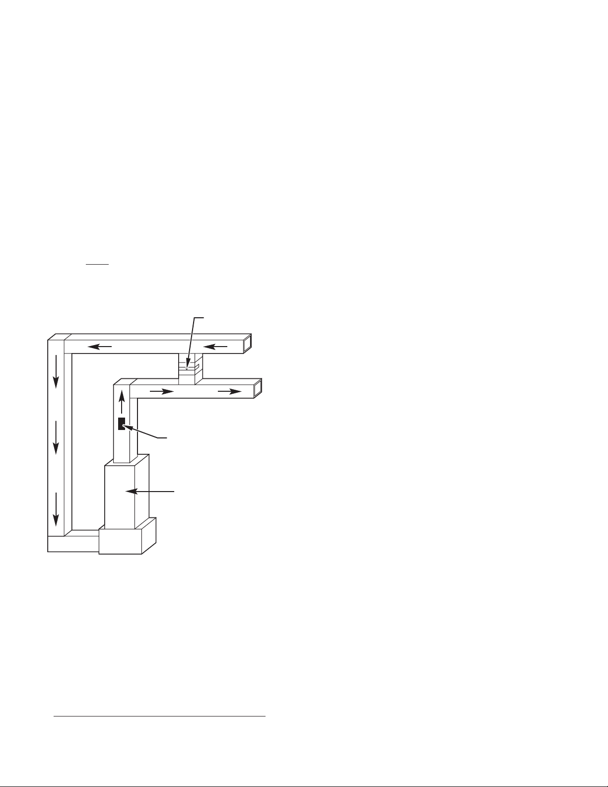
Installation of the Bypass Damper can either be a “Direct-Return”
or “Dump-Zone”. (See Fig. 2 and Fig. 3.)
Location of the Bypass Damperis very important.Listed beloware
a few guidelines for proper location.
BYPASS
RETURN AIR DUCTWORK
SUPPLY AIR DUCTWORK
LEAVING AIR
TEMPERATURE
SENSOR
INDOOR
UNIT
A00190
Fig. 2–Direct Return Installation
1. Location must be accessible for inspection and maintenance.
2. Location must be in an area that has allowed the airflow on
the supply side to become smooth and allows bypassed air
to mix with return-air, before entering the equipment.
3. The leaving air temperature (LAT) must be installed upstream (ahead of) from the bypass inlet.
4. Do not locate too closely to an open return. The bypassed
air could cause the return to become positively pressured.
5. Consult Bypass Damper Installation Instruction for more
information.
B. Task 6–Explanation of the Duct Sizing Worksheet
The Duct Sizing Worksheet will help size the supply ductwork for
a zoning system. Traditional methods, whether zoning was being
applied or not, have been to design duct work at .1 in. wc supply
and .08 in. wc return. But not everyone knew that this was based
on 100 ft of equivalent ductwork. Factoring in the equivalent
lengths of fittings could cause the Total Equivalent Length (TEL)
to go past 100 ft This could leave the ductwork undersized.
When zoning was to be applied to the system, we recommend 25
percent overissuing of the ductwork to handle the varying conditions of airflow in the system. Some distributors/dealers have a
built-in “safety-factor” by designing the system with 30 percent
oversizing. Other manufacturers of zoning products have recommended as much as 50–75 percent oversizing. In most cases, the
oversizing took care of any TEL’s over 100 ft.
The reason for this new Design Guide Worksheet is to help ease
the fear of designing a zoning system. The way the worksheet is
put together was to look at as many scenarios as possible, then
apply three design techniques to each example. Each scenario was
designed at:
1. 25 percent oversizing at .1 in. wc supply
2. 25 percent oversizing at .08 in. wc supply (to compensate
for TEL over 100’)
3. 30 percent oversizing at .1 in. wc supply (to compensate for
TEL over 100’)
In 99 percent of the applications, the ductwork sizes “crunched
out” to the same size.
So, if you have designed a zoning systemin the past, use this guide
to see if the sizes match. If this if your first zoning design, have
faith that the sizes are not too large. Our patented damper
movement will adjust the airflow to where it’s needed. If you are
applying zoning to an existing duct system, compare what you
have to what you need. Then make the necessary adjustments to
the ductwork.
You should have completed Tasks 1–5 of the Duct Sizing
Worksheet by following Tasks 1–5.
NOTE: The use of good take-offs and fittings are critical to the
TEL of any ductwork system. Take-off and fitting Total Equivalent Length (TEL) examples are further explained in the Residential Air System Design (Catalog #791–443).
IV. REFERENCE FOR DUCT SIZING WORKSHEET:
(SEE STEP 6 OF DUCT SIZING WORKSHEET, PAGE 9)
Using Table 1 determine the minimum Main Duct square inches
and the minimum Total Branch square inches by locating the
desired Zone CFM (from Task 3) along the left-verticle column. If
your desired Zone CFM falls between the listed CFM’s, use the
one closest to your calculated CFM. Follow the desired Zone CFM
across until you reach the Equipment Capacity, along the top,
required for your application. Write these values for each zone in
the area provided in Task 6.
NOTE: If two or more zones share a main duct (see Fig. 6) then
add the zone CFM’s together and use that CFM to size the Main
Duct. Then as each zone is “branched-off”, it becomes the zone
“Main Branch” and would be sized based on the individual zone
square inches.
The listed areas (square inches) will providea maximum zone duct
pressure drop of approximately 0.1 in. wc / 100 ft and a maximum
of 900 fpm for main ducts and 700 fpm for branch ducts for sheet
metal ductwork. For “Duct board”, multiply areas by 1.1, or for
“flex-duct” multiply areas by 1.25 to maintain same duct pressure
drop and fpm. If CFM in Step 3 is based on cooling and the design
is NOT based on 400 CFM/ton, divide that CFM by 400. Multiply
the areas by this number (Example: a system design of 350
CFM/ton of airflow, multiply areas by: 350/400 = .88).
NOTE: The “grey-shaded” boxes represent zone CFM’s of less
than 20 percent of the total CFM. The square inches were
increased approximately 10 percent to help deal with situations
where limited zones may be open.
—4—
Page 5
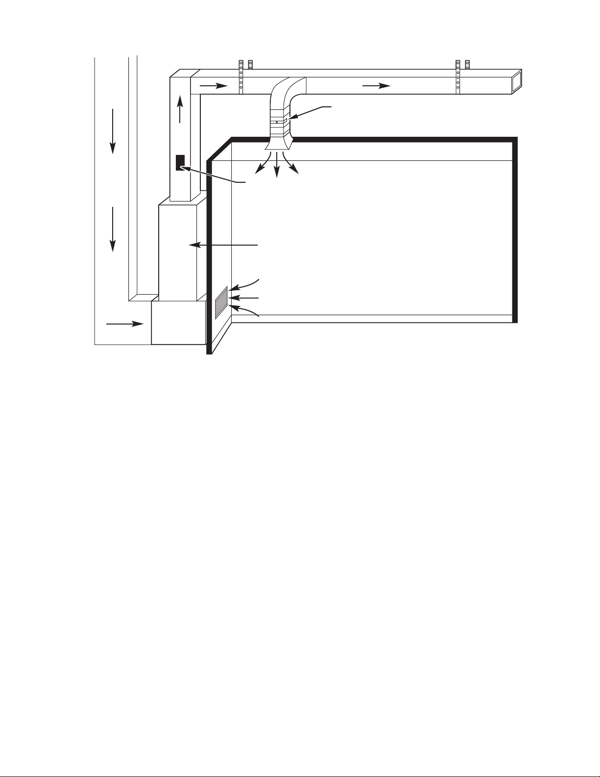
RETURN AIR
DUCT
SUPPLY AIR DUCT
BAROMETRIC
BYPASS
LEAVING AIR
TEMPERATURE
SENSOR
INDOOR UNIT
RETURN AIR
Fig. 3–Dump Zone Installation
V. REFERENCE FOR DUCT SIZING WORKSHEET: (SEE
STEP 7 AT DUCT SIZING WORKSHEET, PAGE 9)
Using Table 2A locate the Minimum Main Duct Area from Step
6 (duct sizing worksheet) to determine the Main Duct size. Select
a damper/duct size at least as large as the area required. Refer to
the Product Data for sizes of dampers. If the Main Duct is split or
runs in two directions, divide up the total zone CFM needed to
each main, locate the square inch areas to meet the required CFM
and then size the dampers.
Using Table 2B locate the Minimum Branch Area from Step 6 to
determine the Branch Duct size(s). Any combination can be used,
as long as the total of the Branch Duct area meets or exceeds the
required amount.
APPENDIX
The following appendix provides worksheets for you to copy and
use when designing a Zone Perfect Plus installation:
• Owner Survey
• Floor Plan Worksheet
A00191
• Duct Sizing Worksheet
• Examples
We will show three examples of the zoning design guide.
Example 1
Light Commercial — Doctor’s Office
Heating Load: 125,000 Btu
Cooling Load: 115,000 Btu
Equipment selected: 581B120125
Example 2
Residential Ranch
Heating Load: 90,000 Btu
Cooling Load: 52,000 Btu
Equipment Selected: 355MAV060100 and 598B060
Example 3
Taking Example 2 and substitute Duct-Board as main and FlexPipe as branch runs. We will begin at Step 6.
—5—
Page 6

Owner Survey
1. How many members are there in your household/building?
2. Describe the activities in your household on an unusual day. In particular, are
there activities that might require extra cooling or heating?
3. Describe the typical usage of the various areas of your home/office throughout the day.
4. What areas, if any, in your home/office that are used infrequently, such as a formal
dining/meeting room, or that are unoccupied for large periods of time during the
day or night?
5. Is there an area in your home/office that will be used for physical activity?
6. Describe the entertaining that you do in your home:
How often do you entertain in the summer? In the winter?
During what times of the day do you typically entertain?
How many people do you usually entertain?
What areas of your home do you use when you entertain?
Are there times when people go in and out of the house frequently (for example,
if you entertain outdoors)?
—6—
A00153
Page 7

7. What temperature do you normally want to maintain in your home/office during the day
in the summer? The nights in the summer? The days in the winter? The nights in the
winter?
8. Are there any times when you want significantly different temperatures in all or part of
your home? If so, in what areas or rooms? How quickly do you want the temperature
change to occur?
9. To what extent do you want to be able to control the temperature in your home?
10. What do you expect from your indoor comfort system?
Additional Questions for an Existing Home/Office Building
1. Are there any areas or rooms in your home/office that are too hot or cold in the winter?
In the summer?
2. Do you have a humidity problem in your home/office? Too much? Too little?
3. How long do you plan to live in your present home?
4. What do you like about your present heating and cooling system? What do you dislike?
A00154
—7—
Page 8

Floor Plan Worksheet
—8—
A98347
Page 9

DUCT SIZING WORKSHEET
Step 1:Calculate Block Load
Heating Load:_____________________ Btuh Cooling Load:____________________ Btuh
Step 2:Room by Room Load
Room Heating Load (Btuh) Cooling Load (Btuh) Airflow (CFM )* Zone Number
____________ ____________ ____________ ____________ _____________
____________ ____________ ____________ ____________ _____________
____________ ____________ ____________ ____________ _____________
____________ ____________ ____________ ____________ _____________
____________ ____________ ____________ ____________ _____________
____________ ____________ ____________ ____________ _____________
____________ ____________ ____________ ____________ _____________
____________ ____________ ____________ ____________ _____________
____________ ____________ ____________ ____________ _____________
____________ ____________ ____________ ____________ _____________
____________ ____________ ____________ ____________ _____________
____________ ____________ ____________ ____________ _____________
____________ ____________ ____________ ____________ _____________
____________ ____________ ____________ ____________ _____________
____________ ____________ ____________ ____________ _____________
____________ ____________ ____________ ____________ _____________
*Highest CFM determined from Heat/Cool Btuh
Step 3: Zone CFM totals
Zone 1 ____________ CFM Zone 5 _____________CFM
Zone 2 ____________ CFM Zone 6 _____________CFM
Zone 3 ____________ CFM Zone 7 _____________CFM
Zone 4 ____________ CFM Zone 8 _____________CFM
Step 4: Equipment Selection
Indoor Section ____________ Outdoor Section _____________
Heating Capacity/CFM ____________ _____________
Cooling Capacity/CFM ____________ _____________
Design CFM ____________
Step 5: Bypass Determination
System Design CFM * ____________ X 0.60 = ______________
* Design CFM can be: Step 1C from above OR if Two Speed/Variable Speed equipment is selected, select low speed CFM value.
Step 6: Zone Minimum Area (sq. in.)(from Table 1, page 21)
CFM Main Duct (sq. in.) Branch Area (sq. in.)
Zone 1 ____________ ____________ ____________
Zone 2 ____________ ____________ ____________
Zone 3 ____________ ____________ ____________
Zone 4 ____________ ____________ ____________
Zone 5 ____________ ____________ ____________
Zone 6 ____________ ____________ ____________
Zone 7 ____________ ____________ ____________
Zone 8 ____________ ____________ ____________
—9—
Page 10

Step 7:Main Trunk (Table 2A) and Branch Duct (Table 2B) Sizes
Zone 1
Main Duct (sq. in.):____________________ = Main Duct Size:____________
Branch (sq. in.):_______________________
Size:__ Qty:___ Area (from Table 2B) =________________+
Size:__ Qty:___ Area (from Table 2B) =________________+
=________________ Total Sq. In.
Zone 2
Main Duct (sq. in.):____________________ = Main Duct Size:____________
Branch (sq. in.):_______________________
Size:__ Qty:___ Area (from Table 2B) =_________________+
Size:__ Qty:___ Area (from Table 2B) =_________________+
=_________________ Total Sq. In.
Zone 3
Main Duct (sq. in.):____________________ = Main Duct Size:____________
Branch (sq. in.):_______________________
Size:__ Qty:___ Area (from Table 2B) =________________+
Size:__ Qty:___ Area (from Table 2B) =________________+
=________________ Total Sq. In.
Zone 4
Main Duct (sq. in.):____________________ = Main Duct Size:____________
Branch (sq. in.):_______________________
Size:__ Qty:___ Area (from Table 2B) =________________+
Size:__ Qty:___ Area (from Table 2B) =________________+
=________________ Total Sq. In.
Zone 5
Main Duct (sq. in.):____________________ = Main Duct Size:____________
Branch (sq. in.):_______________________
Size:__ Qty:___ Area (from Table 2B) =________________+
Size:__ Qty:___ Area (from Table 2B) =________________+
=________________ Total Sq. In.
Zone 6
Main Duct (sq. in.):____________________ = Main Duct Size:____________
Branch (sq. in.):_______________________
Size:__ Qty:___ Area (from Table 2B) =________________+
Size:__ Qty:___ Area (from Table 2B) =________________+
=________________ Total Sq. In.
Zone 7
Main Duct (sq. in.):____________________ = Main Duct Size:____________
Branch (sq. in.):_______________________
Size:__ Qty:___ Area (from Table 2B) =________________+
Size:__ Qty:___ Area (from Table 2B) =________________+
=________________ Total Sq. In.
Zone 8
Main Duct (sq. in.):____________________ = Main Duct Size:___________
Branch (sq. in.):_______________________
Size:__ Qty:___ Area (from Table 2B) =________________+
Size:__ Qty:___ Area (from Table 2B) =________________+
=________________ Total Sq. In.
—10—
Page 11

Waiting Room Room 1 Room 2 Room 3 Room 4
Bath
Office Office Lab
Bathrooms
Fig. 4–Light Commercial Application-Doctor’s Office (unzoned)
A00121
Waiting Room
Bathrooms
Room 1 Room 2 Room 3 Room 4
Office Office Lab
Zone 1
Zone 2
Zone 3
Zone 4
Zone 5
Zone 6
Fig. 5–Light Commercial Application-Doctor’s Office (zoned)
Bath
A00122
—11—
Page 12

DUCT SIZING WORKSHEET-EXAMPLE 1
Step 1:Calculate Block Load
Heating Load:______________125,000 Btuh Cooling Load:_____________115,000 Btuh
Step 2:Room by Room Load
Room Heating Load (Btuh) Cooling Load (Btuh) Airflow (CFM )* Zone Number
Waiting Room ___________ ____________ ____1,000___ _______6_____
Room 1_____ ___________ ____________ _____250____ _______1_____
Room 2_____ ___________ ____________ _____250____ _______1_____
Room 3_____ ___________ ____________ _____250____ _______2_____
Room 4_____ ___________ ____________ _____250____ _______2_____
Back Bathroom ___________ ____________ _____150____ _______4_____
Lab________ ___________ ____________ _____550____ _______4_____
Office_______ ___________ ____________ _____600____ _______3_____
Office/Restrooms ___________ ____________ _____700____ _______5_____
____________ ___________ ____________ ____________ _____________
____________ ___________ ____________ ____________ _____________
____________ ___________ ____________ ____________ _____________
____________ ___________ ____________ ____________ _____________
____________ ___________ ____________ ____________ _____________
____________ ___________ ____________ ____________ _____________
____________ ___________ ____________ ____________ _____________
*Highest CFM determined from Heat/Cool Btuh
Step 3: Zone CFM totals
Zone 1 _________500 CFM Zone 5 __________700 CFM
Zone 2 _________500 CFM Zone 6 ________1,000 CFM
Zone 3 _________600 CFM Zone 7 _____________ CFM
Zone 4 _________700 CFM Zone 8 _____________ CFM
Step 4: Equipment Selection
Indoor Section ____________ Outdoor Section ______581B120
Heating Capacity/CFM ______125,000 _________4,000
Cooling Capacity/CFM ______115,000 _________4,000
Design CFM ________4,000
Step 5: Bypass Determination
System Design CFM * 4,000________ X 0.60 = 2,400_________
(Value MUST be less than smallest zone CFM; otherwise Bypass Damper may be required)
* Design CFM can be: Step 1C from above OR if Two Speed/Variable Speed equipment is selected, select low speed CFM value.
—12—
Page 13

Step 6: Zone Minimum Area (Sq.In.) (From Table 1)
Zone 1 CFM__ 500____
Zone 2 CFM__ 500____
Zone 3 CFM__ 600____
Zone 4 CFM__ 700____
Zone 5 CFM__ 700____
Zone 6 CFM_1,000____
Zone 7 CFM _________
Zone 8 CFM _________
Main Duct __123___Sq.In.
Main Duct __123___Sq.In.
Main Duct __133___Sq.In.
Main Duct __154___Sq.In.
Main Duct __154___Sq.In.
Main Duct __189___Sq.In.
Main Duct ________Sq.In.
Main Duct ________Sq.In.
Branch Area__179___Sq.In.
Branch Area__179___Sq.In.
Branch Area__208___Sq.In.
Branch Area__246___Sq.In.
Branch Area__246___Sq.In.
Branch Area__330___Sq.In.
Branch Area________Sq.In.
Branch Area________Sq.In.
Table 1 Main Duct Area (sq.in.)
Zone CFM Equipment Capacity
2 2.5 3 3.5 4 5 6 7.5 8 8.5 10
200 Main 57 57 57 64 64 64
Branch 66 66 66 75 75 75
300 Main 79 79 79 79 79 87 87
Branch 99 99 99 99 99 110 110
400 Main 86 86 86 86 86 86 104 104 104
Branch 132 132 132 132 132 132 140 140 140
500 Main 113 113 113 113 113 113 113 123 123 123 123
Branch 165 165 165 165 165 165 165 179 179 179 179
600 Main 123 123 123 123 123 123 123 123 133 133 133
Branch 198 198 198 198 198 198 198 198 208 208 208
700 Main 143 143 143 143 143 143 143 143 154 154
Branch 231 231 231 231 231 231 231 231 246 246
Zone 1 & 2
Main Duct Square Inches __ 123 ____ = Main Duct Size___8x18____
Branch Square Inches_____179__
Size__10"___Qty___2___ Area (from Table 2B)=__180___+
Size_______ Qty_______ Area (from Table 2B)=________+
=__180___Total Sq.In.
A00132
Table 2A Main Duct Sizing
Equivalent Areas for Ducts (sq.in.)
Duct Height (in.) Round
Duct Width 8 10 Dia-Inch Sq.In.
86080 850
10 80 87 10 79
12 90 110 12 113
14 105 135 14 154
16 115 157 16 201
18 125 167
Zone 3
Main Duct Square Inches __ 133 ____ = Main Duct Size___10x14____
Branch Square Inches_____208__
Size__7"___Qty___2___ Area (from Table 2B)=__76___+
Size__8"___Qty___2___ Area (from Table 2B)=__135___+
=__211___Total Sq.In.
Table 2B Branch Duct Area (Sq.In.)
Duct Diameter - in.
Quantity 5 6 7 8 10
1 20283860 79
2 40 56 76 135 180
3 60 84 114 180 330
4 80 112 152 235 465
5 100 140 190 300 530
6 120 168 228 365 660
7 140 196 266 430 760
8 160 224 304 500 825
A00133
—13—
Page 14

Zone 4
Main Duct (sq. in.):_________________154 = Main Duct Size:_______10x16
Branch (sq. in.):____________________246
Size:8″ Qty:_3 Area (from Table 2B) =_____________180+
Size:10″ Qty:__1 Area (from Table 2B) =______________79+
=_____________259 Total Sq. In.
Zone 5
Main Duct (sq. in.):_________________154 = Main Duct Size:_______10x16
Branch (sq. in.):____________________246
Size:8″ Qty:__ 3 Area (from Table 2B) =_____________180+
Size:10″ Qty:__1 Area (from Table 2B) =______________79+
=_____________259 Total Sq. In.
Zone 6
Main Duct (sq. in.):_________________189 = Main Duct Size:_______10x20
Branch (sq. in.):____________________330
Size:10″ Qty:__3 Area (from Table 2B) =_____________330+
Size:__ Qty:___ Area (from Table 2B) =________________+
=_____________330 Total Sq. In.
Zone 7
Main Duct (sq. in.):____________________ = Main Duct Size:____________
Branch (sq. in.):_______________________
Size:__ Qty:___ Area (from Table 2B) =________________+
Size:__ Qty:___ Area (from Table 2B) =________________+
=________________ Total Sq. In.
Zone 8
Main Duct (sq. in.):____________________ = Main Duct Size:___________
Branch (sq. in.):_______________________
Size:__ Qty:___ Area (from Table 2B) =________________+
Size:__ Qty:___ Area (from Table 2B) =________________+
=________________+ Total Sq. In.
Zn 6
10x20
Main Duct “A” Main Duct “B”
Zn 5
10x16
Main Duct “A”= 1 + 5 + 6
Zns 1 + 5 + 6= 2200cfm
2200cfm = 346 sq.in.
346 sq.in. = 10x42
Fig. 6–Doctor’s Office Duct Work Layout
Zn 1
8x18
Zn 2
8x18
Zn 4
8x16
Zn 3
8x14
Main Duct “B”= 2 + 3 + 4
Zns 2 + 3 + 4= 1800cfm
1800cfm = 299 sq.in.
299 sq.in. = 10x36
A00134
—14—
Page 15

Living Room Dining Room Kitchen Family Room
Laundry
Master Bedroom
Bedroom 3Bedroom 2Bath
Master Bath
Fig. 7–Residential Application-House Floor Plan (unzoned)
A00186
Master Bedroom
Master Bath
Zone 1 Zone 2 Zone 3 Zone 4
Dining RoomLiving Room
Kitchen Family Room
Laundry
Bedroom 3Bedroom 2Bath
Bedroom 4
Fig. 8–Residential Application-House Floor Plan (zoned into four areas)
A00187
—15—
Page 16

DUCT SIZING WORKSHEET-EXAMPLE 2
Step 1:Calculate Block Load
Heating Load:__________90,000_____ Btuh Cooling Load:_________52,000_____ Btuh
Step 2:Room by Room Load
Room Heating Load (Btuh) Cooling Load (Btuh) Airflow (CFM)* Zone Number
Living Room_ ___________ ____________ ______150___ _______3_____
Dining Room/Foyer ___________ ____________ ______150___ _______3_____
Kitchen/Dinette ___________ ____________ ______200___ _______4_____
Family Room_ ___________ ____________ ______200___ _______4_____
Laundry Room ___________ ____________ ______300___ _______4_____
Master Bedroom/Bathroom ___________ ____________ ______400___ _______1_____
Bedrooms 2-4/Bathroom ___________ ____________ ______500___ _______2_____
____________ ___________ ____________ ____________ _____________
____________ ___________ ____________ ____________ _____________
____________ ___________ ____________ ____________ _____________
____________ ___________ ____________ ____________ _____________
____________ ___________ ____________ ____________ _____________
____________ ___________ ____________ ____________ _____________
____________ ___________ ____________ ____________ _____________
____________ ___________ ____________ ____________ _____________
____________ ___________ ____________ ____________ _____________
*Highest CFM determined from Heat/Cool Btuh
Step 3: Zone CFM totals
Zone 1 _____400____ CFM Zone 5 _____________CFM
Zone 2 _____500____ CFM Zone 6 _____________CFM
Zone 3 _____300____ CFM Zone 7 _____________CFM
Zone 4 _____700____ CFM Zone 8 _____________CFM
Step 4: Equipment Selection
Indoor Section ____355MAV06100__ Outdoor Section _________598B060__
Heating Capacity/CFM ____95,000/62,000__ __________1320/860__
Cooling Capacity/CFM ____53,000/34,000__ _______2,000/1,200__
Design CFM _____1,200 (low speed A/C)
Step 5: Bypass Determination
System Design CFM * ___1,200____ X 0.60 = _______720____
(Value MUST be less than smallest zone CFM; otherwise Bypass Damper may be required)
* Design CFM can be: Step 1C from above OR if Two Speed/Variable Speed equipment is selected, select low speed CFM value...used 2-speed A/C unit/low CFM=1200CFM
—16—
Page 17

Step 6: Zone Minimum Area (Sq.In.) (From Table 1)
Zone 1 CFM__ 400____
Zone 2 CFM__ 500____
Zone 3 CFM__ 300____
Zone 4 CFM__ 700____
Zone 5 CFM_________
Zone 6 CFM_________
Zone 7 CFM _________
Zone 8 CFM _________
Main Duct ___86___Sq.In.
Main Duct __113___Sq.In.
Main Duct ___87___Sq.In.
Main Duct __143___Sq.In.
Main Duct ________Sq.In.
Main Duct ________Sq.In.
Main Duct ________Sq.In.
Main Duct ________Sq.In.
Branch Area__132___Sq.In.
Branch Area__165___Sq.In.
Branch Area__110___Sq.In.
Branch Area__231___Sq.In.
Branch Area________Sq.In.
Branch Area________Sq.In.
Branch Area________Sq.In.
Branch Area________Sq.In.
Table 1 Main Duct Area (sq.in.)
Zone CFM Equipment Capacity
2 2.5 3 3.5 4 5 6 7.5 8
200 Main 57 57 57 64 64 64
Branch 66 66 66 75 75 75
300 Main 79 79 79 79 79 87 87
Branch 99 99 99 99 99 110 110
400 Main 86 86 86 86 86 86 104 104 104
Branch 132 132 132 132 132 132 140 140 140
500 Main 113 113 113 113 113 113 113 123 123
Branch 165 165 165 165 165 165 165 179 179
600 Main 123 123 123 123 123 123 123 123 133
Branch 198 198 198 198 198 198 198 198 208
700 Main 143 143 143 143 143 143 143 143
Branch 231 231 231 231 231 231 231 231
A00135
Step 7:Main Trunk (Table 2A) and Branch Duct (Table 2B) Sizes
Zone 1
Main Duct (sq. in.):__________________86 = Main Duct Size:________8x12
Branch (sq. in.):____________________132
Size:6″ Qty:__2 Area (from Table 2B) =_______________56+
Size:7″ Qty:__2 Area (from Table 2B) =_______________76+
=______________132 Total Sq. In.
Zone 2
Main Duct (sq. in.):_________________113 = Main Duct Size:________8x16
Branch (sq. in.):___________________165
Size:6″ Qty:__2 Area (from Table 2B) =_______________56+
Size:7″ Qty:__3 Area (from Table 2B) =______________114+
=______________165 Total Sq. In.
Zone 3
Main Duct (sq. in.):__________________87 = Main Duct Size:________8X12
Branch (sq. in.):____________________110
Size:7″ Qty:__3 Area (from Table 2B) =______________114+
Size:__ Qty:___ Area (from Table 2B) =_________________+
=______________114 Total Sq. In.
—17—
Page 18

Zone 4
Main Duct Square Inches__143____ = Main Duct Size __8x20_____
Table 2A Main Duct Sizing
Equivalent Areas for Ducts (sq.in.)
Duct Height (in.) Round
Duct Width 8 10 Dia-Inch Sq.In.
86080 850
10 80 87 10 79
12 90 110 12 113
14 105 135 14 154
16 115 157 16 201
18 125 167
20 145 190
22 155 210
24 165 215
Branch Square Inches_____231__
Size__6"___Qty___2___ Area (from Table 2B)=___56___+
Size__8"___Qty___3___ Area (from Table 2B)=__180___+
=__236___Total Sq.In.
Table 2B Branch Duct Area (Sq.In)
Duct Diameter - in.
Quantity 5 6 7 8 10
1 20283860 79
2 40 56 76 135 180
3 60 84 114 180 330
4 80 112 152 235 465
5 100 140 190 300 530
6 120 168 228 365 660
7 140 196 266 430 760
8 160 224 304 500 825
A00136
Zn 1
8x12
Zn 3
8x12
Fig. 9–Residential Duct Work Layout
Zn 4
8x20
Zn 2
8x16
A00137
—18—
Page 19

DUCT SIZING WORKSHEET-EXAMPLE 3
Starting from Step 6, we need to multiply the Main Duct Square Inches by 1.1 and the Branch Area
by 1.25.
Example: Zone 1 - Main Duct - 86x1.1 = 95 Sq.In.
Branch Area - 132x1.25 = 165 Sq.In.
Step 6: Zone Minimum Area (Sq.In.) (From Table 1)
Zone 1 CFM ___400____Main Duct ___95____Sq.In. Branch Area__165____Sq.In.
Zone 2 CFM ___500____Main Duct __124____Sq.In. Branch Area__206____Sq.In.
Zone 3 CFM ___300____Main Duct ___96____Sq.In. Branch Area__138____Sq.In.
Zone 4 CFM ___700____Main Duct __157____Sq.In. Branch Area__289____Sq.In.
Zone 5 CFM __________Main Duct _________Sq.In. Branch Area_________Sq.In.
Zone 6 CFM __________Main Duct _________Sq.In. Branch Area_________Sq.In.
Zone 7 CFM __________Main Duct _________Sq.In. Branch Area_________Sq.In.
Zone 8 CFM __________Main Duct _________Sq.In. Branch Area_________Sq.In.
Step 7: Main Trunk (Table 2A) and Branch Duct Size (Table 2B) Sizes
Zone 1
Main Duct Square Inches ___95____ Main Duct Size___8x14____
Table 2A Main Duct Sizing
Equivalent Areas for Ducts (sq.in.)
Duct Height (in.) Round
Duct Width 8 10 Dia-Inch Sq.In.
86080 850
10 80 87 10 79
12 90 110 12 113
14 105 135 14 154
16 115 157 16 201
18 125 167
A00138
—19—
Page 20

Branch Square Inches_____165__
Table 2B Branch Duct Area (Sq.In)
Duct Diameter - in.
Quantity 5 6 7 8 10
1 20283860 79
2 40 56 76 135 180
3 60 84 114 180 330
4 80 112 152 235 465
5 100 140 190 300 530
6 120 168 228 365 660
7 140 196 266 430 760
8 160 224 304 500 825
Size_______Qty_______ Area (from Table 2B)=________+
Size__8"___Qty___3___ Area (from Table 2B)=__180___+
=__180___Total Sq.In.
Zone 2
Main Duct Square Inches___124____ =Main Duct Size ___8x18___
Branch Square Inches ___206____
Size_______Qty_______ Area (from Table 2B)=________+
Size__8"___Qty___4___ Area (from Table 2B)=__235___+
=__235___Total Sq.In.
Zone 3
Main Duct Square Inches___96____ =Main Duct Size ___8x14___
Branch Square Inches ___138____
Size_______Qty_______ Area (from Table 2B)=________+
Size__7"___Qty___4___ Area (from Table 2B)=__152___+
=__152___Total Sq.In.
Zone 4
Main Duct Square Inches___157____ =Main Duct Size ___8x24___
Branch Square Inches ___289____
Size__8"___Qty___5___ Area (from Table 2B)=__300___+
Size_______Qty_______ Area (from Table 2B)=________+
=__300___Total Sq.In.
A00139
—20—
Page 21

TABLE 1–ZONE CFM
MAIN & BRANCH DUCT AREA (SQ. IN.)
Equipment Capacity
2 2.5 3 3.5 4 5 6 7.5 8 8.5 10 12.5
200
300
400
500
600
700
800
900
1000
1100
1200
1300
1400
1500
1600
1700
1800
1900
2000
2100
2200
2300
2400
2500
Shaded areas represent less than 20 percent of total CFM, increased by one size.
*Main Duct sq in. aredetermined by multiplying CFM by 1.3 (200x1.3=260). Then size duct based on square inches of round pipe. Example: 260CFM.1 in. wc = 8.5” round
pipe=57sqin.
**Branch duct sq in. are based on 6” pipe delivering 100 CFM .1 in. wc X 1.3 = 130 CFM. Take 130 CFM .1 in. wc =6.5”pipe = 33 sq in. Example: 33 sq in. /100 CFM X
2=66CFM
Main 57** 57 57 64 64 64
Branch 66*** 66 66 75 75 75
Main 79 79 79 79 79 87 87
Branch 99 99 99 99 99 110 110
Main 86 86 86 86 86 86 104 104 104
Branch 132 132 132 132 132 132 140 140 140
Main 113 113 113 113 113 113 113 123 123 123 123
Branch 165 165 165 165 165 165 165 179 179 179 179
Main 123 123 123 123 123 123 123 123 133 133 133 133
Branch 198 198 198 198 198 198 198 198 208 208 208 208
Main 143 143 143 143 143 143 143 143 154 154 154
Branch 231 231 231 231 231 231 231 231 246 246 246
Main 154 154 154 154 154 154 154 154 154 154 165
Branch 264 264 264 264 264 264 264 264 264 264 273
Main 165 165 165 165 165 165 165 165 165 177
Branch 297 297 297 297 297 297 297 297 297 311
Main 189 189 189 189 189 189 189 189 189 201
Branch 330 330 330 330 330 330 330 330 330 330
Main 201 201 201 201 201 201 201 201 201
Branch 363 363 363 363 363 363 363 363 363
Main 214 214 214 214 214 214 214 214 214
Branch 396 396 396 396 396 396 396 396 396
Main 227 227 227 227 227 227 227 227
Branch 429 429 429 429 429 429 429 429
Main 241 241 241 241 241 241 241 241
Branch 462 462 462 462 462 462 462 462
Main 254 254 254 254 254 254 254
Branch 495 495 495 495 495 495 495
Main 269 269 269 269 269 269 269
Branch 528 528 528 528 528 528 528
Main 284 284 284 284 284 284
Branch 561 561 561 561 561 561
Main 299 299 299 299 299 299
Branch 594 594 594 594 594 594
Main 314 314 314 314 314
Branch 627 627 627 627 627
Main 314 314 314 314 314
Branch 660 660 660 660 660
Main 330 330 330 330
Branch 693 693 693 693
Main 346 346 346 346
Branch 726 726 726 726
Main 363 363
Branch 759 759
Main 363 363
Branch 792 792
Main 380 380
Branch 825 825
—21—
Page 22

TABLE 2A-MAIN DUCT SIZING
EQUIVALENT AREAS FOR DUCTS (SQ. IN.)
Duct Height Round
Duct Width 8(in.) 10(in.) Dia-in. Sq-in.
8 60 80 8 50
10 80 87 10 79
12 90 110 12 113
14 105 135 14 154
16 115 157 16 201
18 125 167 18 269
20 145 190 20 314
22 155 210 22 380
24 165 215
26 227
28 241
30 254
32 269
34 284
36 299
38 314
40 330
42 346
44 363
TABLE 2B-BRANCH DUCT AREA (SQ. IN.)
DUCT DIAMETER - IN.
Quantity 5 6 7 8 10121416
1 20 28 38 50 79 113 154 201
2 40 56 76 135* 180 365 565 760
3 60 84 114 180 330 530 795 825
4 80 112 152 235 465 730 825
5 100 140 190 300 530 825
6 120 168 228 365 660
7 140 196 266 430 760
8 160 224 304 500 825
9 180 252 342 565
10 200 280 380 630
11 220 308 418 660
12 240 336 456 726
13 260 364 494 795
14 280 392 532
15 300 420 570
Two 8” pipes have approximately the same volume of five 6” pipes. To keep static approximately .1 in. wc, the numbers were adjusted to handle same CFM .1 in. wc.
Example:
6”pipe=100CFM.1in.wcX5=500CFM
8”pipe=240CFM.1in.wcX2=480CFM.
Square inches adjusted to match sizes with Table 1 — Branch values.
—22—
Page 23

—23—
Page 24

© 2000 Bryant Heating & Cooling Systems 7310 W. Morris St. Indianapolis, IN 46231
—24—
Printed in U.S.A. ap17–5 Catalog No. 809–651
 Loading...