

Page 1
CONTENTS
Page
GENERAL ......................................1
CONFIGURATION ...............................1,2
I. Thermostat Display .........................1
II. Heat or Cool Indicator ......................1
III. Thermostat Front Panel Buttons ..............1
IV. Thermostat Inner Panel Buttons ..............2
OPERATION ....................................3
I. Mode .....................................3
II. Two-Stage Operation .......................3
III. Electric Heat ..............................3
IV. Dry Contact Switch/External Device ...........3
V. Remote Temperature Sensor .................3
VI. Outdoor Temperature Sensor ................3
IMPORT ANT: Read entire instructions before configuringthe
thermostat.
GENERAL
Bryant’scommercial, non-programmable thermostats are wallmounted, low-voltage thermostats which maintain room temperature by controlling the operation of an HVAC (heating,
ventilation, and air conditioning) system. Separate heating
and cooling set points and auto-changeover capability allow
flexibility. Dry contacts are provided for optional wiring to
field-supplied external output device to control thermostat to
occupied and unoccupied set points for energy savings.
Batteries are not required. During power interruption the internal NEVERLOST™ memory stores thermostat configuration for an unlimited time.
IMPORT ANT: The thermostat has a configurable security level.
If certain functions are not available (such as changing set
points), the thermostat security level may be configured to
exclude those functions. Call the installer to reconfigure the
security level.
CONFIGURATION
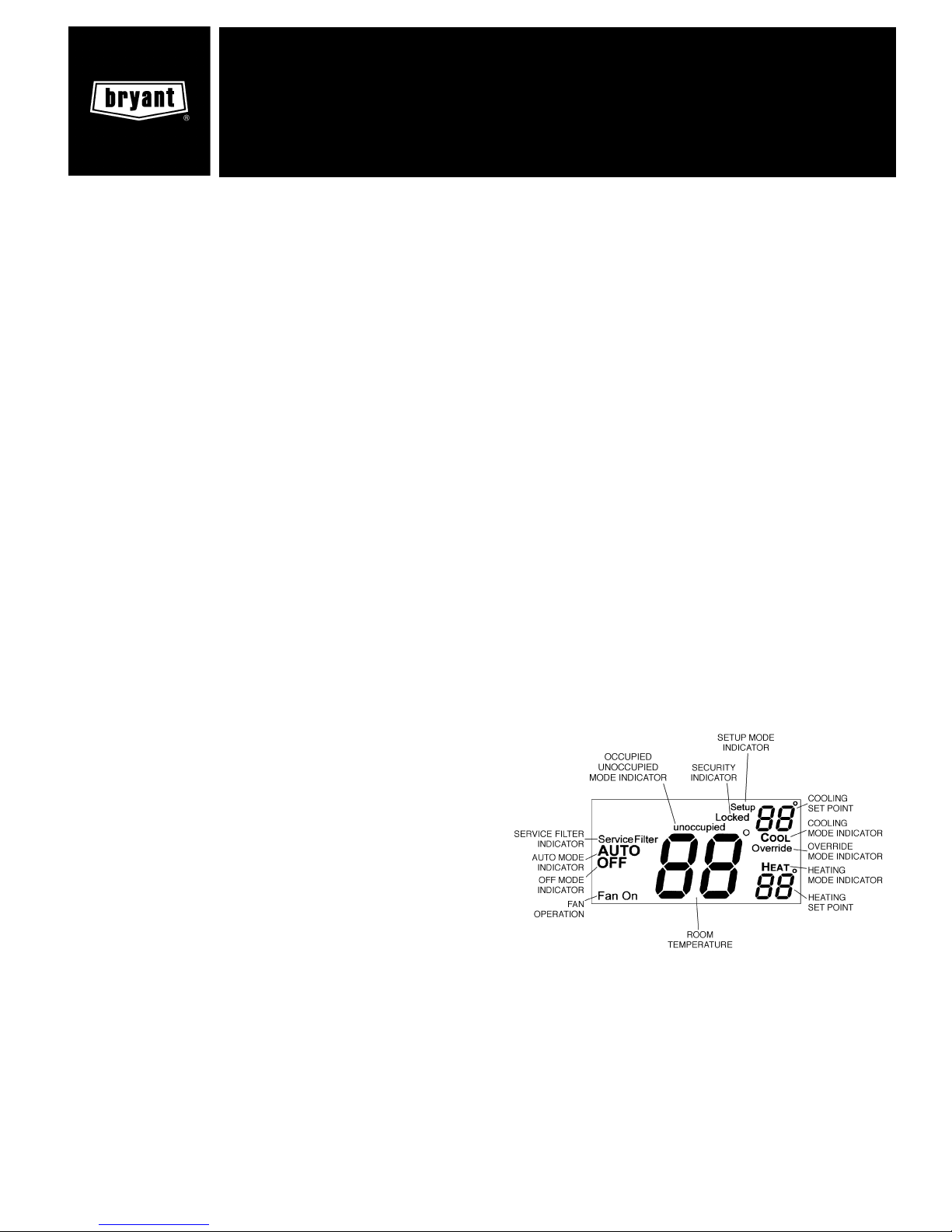
I. THERMOSTAT DISPLAY
The thermostat display is located in the center of the thermostat. See Fig. 1. The following information can be displayed on the screen:
• mode (OFF, HEAT, COOL, or AUTO)
• fan setting (FAN ON or blank)
• override indication
• room temperature
• desired temperature
• service filter indicator
• outside temperature
• Occupied or Unoccupied mode (with dry contact connection to external device)
• setup indicator (configuration mode)
• lock indicator
II. HEAT OR COOL INDICATOR
A Heat or Cool indicator is located on the bottom left cover of
the thermostat. See Fig. 2. The light will be red if the thermostat is in Heating mode. The light will be green if the thermostat is in Cooling mode.
III. THERMOSTAT FRONT PANEL BUTTONS
The thermostat has buttons on the front cover which are used
to raise or lower the desired set point and override the current program. See Fig. 2.
A. Set Point Buttons
The UP ARROW and DOWN ARROW buttons will raise or
lower the current desired temperature set point. If the thermostat is in AUTO mode, pressing the UP ARROW or DOWN
ARROW buttons will adjust both the heating and cooling set
points. Pressing the UP ARROW or DOWN ARROW buttons
in Cooling mode will adjust only the cooling set points. Pressing the UP ARROW or DOWN ARROW buttons in Heating
mode will adjust only the heating set points. The UP ARROW and DOWN ARROW buttons are also used in Programming mode.
Fig. 1 — Thermostat Display
user’s information manual
TEMPSURE COMMERCIAL
THERMOSTAT-PROGRAMMABLE
(P/N TSTATBBP071-01)
Cancels: New OM TSTAT-5
11/15/98
Page 2
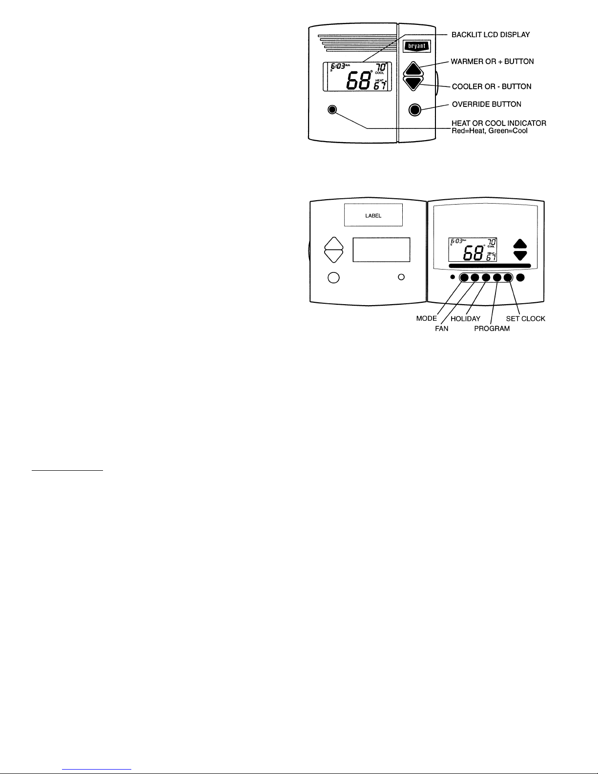
B. Override Button
The Override button is used to force the thermostat from Unoccupied mode into the Occupied mode comfort settings when
used with dry contacts and an external device. The Override
period will be set at 30 minutes. The thermostat will then
return to Unoccupied mode. To increase the amount of time
in Override mode, press the Override button again. Thirty
minutes of override time will be added for each time the Override button is pressed up to a maximum of 4 hours. After the
4-hour limit has been reached, press the Override button again
to cancel Override mode.
While in Override mode, the Override icon and the Occupied
icon will be displayed on the thermostat. The time of day and
the minutes remaining in Override mode will alternate on
the thermostat display.
The set points are adjustable with the UPARROW and DOWN
ARROW keys during Override mode.
NOTE: The Unoccupied mode is configured by the installer.
IV. THERMOSTAT INNER PANELS BUTTONS
The thermostat has inner panel buttons which are used to
change the configuration of the thermostat, set the mode, and
reset the filter. The buttons are accessible from underneath
the thermostat cover. To access the inner panel buttons, pull
on the hinged thermostat cover. See Fig. 3. The programming buttons are: Mode, Fan, Emergency Heat, Backlight,
and Reset Filter.
The UP ARROW and DOWN ARROW buttons are used to
choose configuration settings. The buttons are also used to
answer yes or no.
A. Mode Button Operation
The Mode button selects the operating mode of the thermostat. If OFF is selected, the thermostat will not enter Heating or Cooling mode. If HEAT is selected, the thermostat will
only enter Heating mode (if the room temperature is below
the heating set point). If COOL is selected, the thermostat
will only enter Cooling mode (if the room temperature is above
the cooling set point). If AUTO is selected, the thermostat will
enter Heating or Cooling mode based on the room temperature and the heating and cooling set points.
Auto-Changeover
When the thermostat mode is set to AUTO, the thermostat
will provide automatic changeover from Heating to Cooling
mode and Cooling to Heating mode when required. The thermostat will automatically switch to maintain the desired temperature setting. The thermostat does not need to be manually changed from heating to cooling or cooling to heating
operation.
B. Fan Button Operation
The Fan button selects fan operation. When the fan is set to
FAN ON, the fan will run continuously for improved air
circulation.
NOTE: When the thermostat is in Unoccupied mode (with
Dry Contact Switch), the fan will run only during heating or
cooling operation, even if the fan is set to FAN ON.
When the fan is not set to FANON (no icon displayed on thermostat screen), the fan will run during heating and cooling
operation only.
C. Emergency Heat Button
Emergency heat is available for heat pump applications. To
turn on emergency heat, press the Emergency Heat button.
An ‘‘EH’’ will be displayed. During emergency heat, the fan
will operate and the second stage of heat will be energized
(locking out the first stage compressor). To exit emergency
heat, press the Emergency Heat button. During emergency
heat, only OFF and HEAT modes are available.
D. Backlight Button
The Backlight button is used to change the setting of the Backlight display. If the configuration is set to Yes, the backlight
will be lit continuously. If the configuration is set to No, the
display will be lit only after a button is pushed. The display
will stay lit until action has ceased.
E. Reset Filter Button
The Reset Filter button is used by the service person to reset
the Service Filter icon display.
If the Reset Filter button is pressed during normal thermostat operation, the number of hours of fan operation is
displayed.
F. Keypad Lock
The thermostat has a keypad lockout feature which will not
acknowledge front panel buttons until the lockout sequence
is entered. To disable or lock the keypad, press and hold the
Mode button. While holding down the Mode button, press the
UP and DOWN ARROW buttons simultaneously.The‘‘Locked’’
icon will appear on the display.
The thermostat is unlocked by performing the same procedure. Press and hold the Mode button. While holding down
the Mode button, press the UP and DOWN ARROW buttons
simultaneously. The ‘‘Locked’’ icon will be removed from the
display.
Fig. 2 — Thermostat Front Panel Buttons
Fig. 3 — Thermostat Inner Panel Buttons
—2—
Page 3

OPERATION
I. MODE
The Mode button selects the operating mode of the thermostat. If OFF is selected, the thermostat will not enter Heating or Cooling mode. If HEAT is selected, the thermostat will
only enter Heating mode (if the room temperature is below
the heating set point). If COOL is selected, the thermostat
will only enter Cooling mode (if the room temperature is above
the cooling set point). If AUTO is selected, the thermostat will
enter Heating or Cooling mode based on the room temperature and the heating and cooling set points.
II. TWO-STAGE OPERATION
The second stage of heat or cool is turned on when the first
stage has been on for a minimum of 2 minutes and the temperature differential from the set point is equal to or greater
than the set point plus the deadband plus 2 degrees.
III. ELECTRIC HEAT
When the Electric Heat option in the advanced set up is set
to ON, the thermostat will turn on the fan immediately any
time there is a heat demand. This feature should only be used
on electric heating applications. Do not use with gas heat.
IV. DRY CONTACT SWITCH/EXTERNAL DEVICE
A dry contact switch is provided to allow an external device
to force the thermostat into Unoccupied mode. When the thermostat is forced into Unoccupied mode via the dry contact
closure, the Unoccupied mode icon will blink each second.
A. Soft Start
When multiple thermostats are controlled by the same external device, a Soft Start option can be used to stagger the start
times of the HVAC equipment. This feature may cause a delay in operation after entering or leaving Unoccupied mode.
V. REMOTE TEMPERATURE SENSOR
A remote temperature sensor is available to read the temperature from a space. If a remote temperature sensor is connected, the thermostat will ignore the reading of its internal
sensor. When the thermostat is using a reading from a remote sensor, the degree symbol above the temperature reading will blink.
VI. OUTDOOR TEMPERATURE SENSOR
An outdoor temperature sensor may be provided to read the
outside temperature. Outside temperature can be viewed by
pressing and holding the Mode button for 2 seconds.
—3—
Page 4

Copyright 1998 Bryant Heating & Cooling Systems CATALOG NO. 809-695Printed in U.S.A.
 Loading...