

Page 1
Installation and Start-Up Instructions
EVOLUTION NETWORK INTERFACE MODULE
SYSTXBBNIM01
Network Interface Module
SYSTXBBNIM01
NOTE: Read the entire instruction manual before starting the
installation.
This symbol → indicates a change since the last issue.
TABLE OF CONTENTS
SAFETY CONSIDERATIONS.....................................................1
INTRODUCTION..........................................................................1
INSTALLATION...........................................................................1
Check Equipment and Job Site...........................................1
Component Location and Wiring Considerations..............1
Install Components..............................................................2
Ventilator (HRV/ERV) Wiring...........................................2
Dual Fuel with 1-Speed Heat Pump Wiring......................2
Var.-Spd. Indoor Units with 2-Spd. Outdoor Unit Wiring.2
SYSTEM START-UP....................................................................2
LED INDICATORS.......................................................................2
FUSE ..............................................................................................2
24 VAC POWER SOURCE..........................................................2
SAFETY CONSIDERATIONS
Read and follow manufacturer instructions carefully. Follow all
local electrical codes during installation. All wiring must conform
to local and national electrical codes. Improper wiring or installation may damage Evolution Control System. Recognize safety
information. This is the safety-alert symbol
symbol on the equipment and in the instruction manual, be alert to
the potential for personal injury. Understand the signal words
DANGER, WARNING, and CAUTION. These words are used
with the safety-alert symbol. DANGER identifies the most serious
hazards, which will result in severe personal injury or death.
WARNING signifies a hazard, which could result in personal
injury or death. CAUTION is used to identify unsafe practices,
which would result in minor personal injury or product and
property damage. NOTE is used to highlight suggestions which
will result in enhanced installation, reliability, or operation.
. When you see this
A03231
Cancels: NEW II NIM01-0-1
02-04
INTRODUCTION
The Network Interface Module (NIM) is used to interface the
following devices to the Evolution ABCD bus so they can be
controlled by the Evolution System. The following devices do not
have communication ability and the NIM is required to control:
• A Heat Recovery Ventilator / Energy Recovery Ventilator
(HRV/ERV) (when zoning is not applied).
• A non-communicating single-speed heat pump with a variablespeed furnace (dual fuel application only).
• A non-communicating two-speed outdoor unit (R-22 Series-A
unit).
INSTALLATION
I. CHECK EQUIPMENT AND JOB SITE
INSPECT EQUIPMENT — File claim with shipping company,
prior to installation, if shipment is damaged or incomplete.
II. COMPONENT LOCATION AND WIRING CONSIDERATIONS
WARNING: ELECTRICAL SHOCK HAZARD
Failure to follow this warning could result in personal
injury or possible equipment damage.
Disconnect power before beginning installation.
NOTE: All wiring must comply with national, local, and state
codes.
LOCATING NETWORK INTERFACE MODULE (NIM)
— Select a location near the variable-speed furnace or fan coil
where wiring from equipment can come together easily.
NOTE: Do not mount NIM in outdoor unit. The NIM is
approved for indoor use only and should never be installed with
any of its components exposed to the elements.
The NIM may be installed in any area where temperature remains
between 32° and 158° F, and there is no condensation. Remember
that wiring access is likely the most important consideration.
CAUTION: ELECTRICAL OPERATION HAZARD
Failure to follow this caution will result in equipment
damage or improper operation.
To prevent possible damage to NIM, do not mount on
plenum, duct work, or flush against furnace.
WIRING CONSIDERATIONS — Ordinary thermostat wire is
ideal when wiring the Evolution System (shielded cable is not
necessary). Use 18 - 22 AWG or larger for typical installations.
Lengths over 100 ft. should use 18 AWG or larger wire. Cut off or
fold back and tape any unneeded conductors. Plan the routing of
wiring early to avoid possible problems later.
NOTE: ABCD bus wiring only requires a four-wire connection;
however, it is good practice to run thermostat cable having more
than four wires in the event of a damaged or broken wire during
installation.
—1—
Page 2

The following color-code is recommended for each ABCD bus
connection:
A — Green = Data A
B — Yellow = Data B
C — White = 24VAC (Common)
D — Red = 24VAC (Hot)
It is not mandatory that the above color code be used, but each
ABCD connector in the system MUST be wired consistently.
NOTE: Improper wiring of the ABCD connector will cause the
Evolution System to operate improperly. Check to make sure all
wiring is correct before proceeding with installation or turning on
power.
III. INSTALL COMPONENTS
INSTALL NETWORK INTERFACE MODULE — Plan wire
routing before mounting. The Evolution Network Interface Module is designed so that wires can enter it from the sides.
1. Remove top cover and mount NIM to wall using screws and
wall anchors provided.
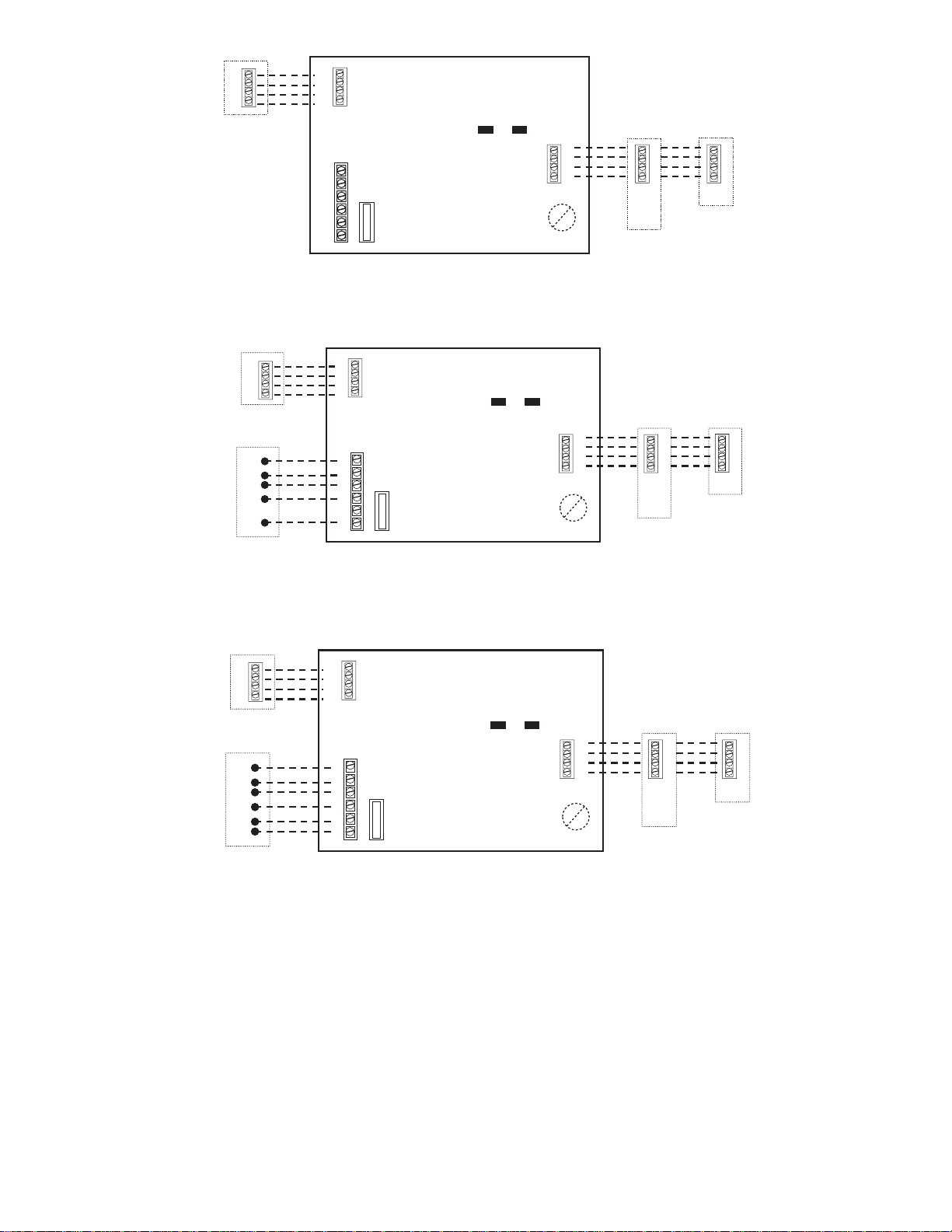
IV. VENTILATOR (HRV/ERV) WIRING
HRV / ERV INSTALLATION — The NIM can control a Bryant
Heat Recovery Ventilator / Energy Recovery Ventilator (HRV /
ERV). Connect four wires from ventilator control board (see
ventilator installation instructions for details) to connector labeled
(YRGB). This label identifies the color of the wire to match the
ventilator wire colors (Y=yellow, R=red, G=green, B=blue or
black). See Fig. 2 for ventilator (HRV / ERV) connection.
NOTE: If system is zoned (contains an Evolution Damper Control Module), the ventilator may be connected either directly to the
Damper Control module or to the NIM. In either case, the
Evolution Zone Control will properly discover the ventilator.
V. DUAL FUEL WITH 1-SPEED HEAT PUMP WIRING
DUAL FUEL INSTALLATION WITH 1-SPEED HEAT
PUMP — The NIM is needed when a variable-speed furnace is
applied with a Bryant single-speed (non-communicating) heat
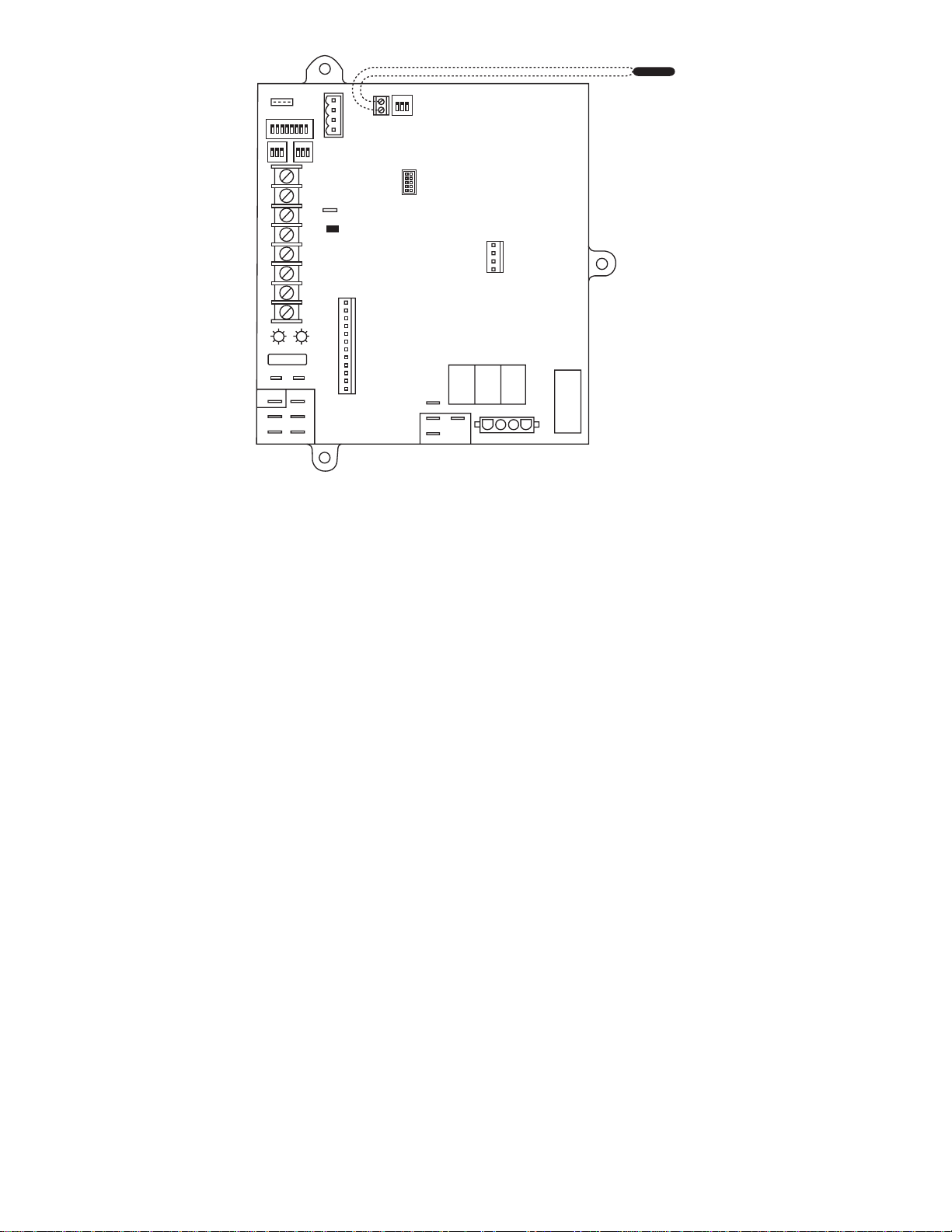
pump. See Fig. 3 for wiring details. An outdoor air temperature
sensor MUST be connected to furnace control board for proper
operation (see Fig. 5 for details).
VI. VARIABLE-SPEED INDOOR UNIT WITH 2-SPEED
OUTDOOR UNIT WIRING
2-SPEED NON-COMMUNICATING OUTDOOR UNIT —
The NIM can control a 2-speed non-communicating air conditioner or heat pump (R-22 Series-A unit) with a variable-speed
indoor unit. See Fig. 4 for wiring details.
SYSTEM START-UP
Follow the system start-up process outlined in the Evolution Zone
Control or Evolution Control installation instructions.
LED INDICATORS
Under normal operation, the Yellow and Green LEDs will be on
continuously (solid). If the NIM does not successfully communicate with the Evolution Control, the Green LED will not be on. If
there are faults present, the Yellow LED indicator will blink a
two-digit status code. The first digit will blink at a fast rate, the
second at a slow rate.
STATUS CODE DESCRIPTION
16 = Communication Failure
45 = Board Failure
46 = Low Input Voltage
FUSE
A 3-amp automotive type fuse is used to protect the NIM from
overloading the outdoor unit R output. If this fuse fails, there is
likely a short in the wiring to the device being controlled by the
NIM. After short in wiring is fixed, fuse should be replaced with
an identical 3 amp automotive fuse.
24 VAC POWER SOURCE
The NIM receives its 24 VAC power from the indoor unit C and
D terminals (via ABCD connector bus). In most applications, there
is sufficient power (VA capacity) available from the indoor unit
transformer to accommodate a ventilator and / or outdoor unit
connection. No additional transformer is required.
—2—
Page 3
B
G
R
Y
Ventilator
Connection
B
G
R
Y
Yellow
Green
C
W
O
Y1
Y2
R
FUSE
A
B
C
D
Indoor
A
B
C
D
A
B
C
D
User
Interface
Unit
B
G
R
Y
Ventilator
(if used)
C
W2
O
Y
R
1 Spd. Heat Pump
Fig. 3 — Variable-Speed Furnace with 1-Spd. Heat Pump (Dual Fuel)
B
G
R
Y
V entilator
(if used)
C
W2
O
Y1
Y2
R
Outdoor 2-Spd.
AC or HP
(R-22 Series-A unit)
Fig. 4 — 2-Spd Non-Communicating AC or HP (R-22 Series-A Unit)
Fig. 2 — Ventilator (HRV / ERV) Connection
B
G
R
Y
YellowGreen
A
B
C
W
O
Y1
Y2
FUSE
R
B
G
R
Y
Yellow
Green
C
W
O
Y1
Y2
FUSE
R
C
D
A
B
C
D
with Variable-Speed Indoor Unit
A
B
C
D
Furnace
Indoor
Unit
A
B
C
D
A03143
A
B
C
D
User
Interface
A03144
User
Interface
A03145
A
B
C
D
—3—
Page 4
PL4
1
1
ABCD
HUM
OAT
PL9
1
PL7
1
PL8
OAT
Sensor
GDHUMY1W2
24Y
RY/Y2W/W1COM
STATUS
CODE
FUSE 3-AMP
SEC-2 SEC-1
FAC-2
LEDS
ACRDJ
COMM
PL1
CARRIER PN
NEUTRAL-L2
1
1-AMPS 115VAC
EAC-1
L1
PL3
1
PL2
VS HSI HI LO
Fig. 5 — HK42FZ022 Furnace Board with
Outdoor Air Temperature Connection
1
A03230
© 2004 Bryant Heating & Cooling Systems 7310 W. Morris St. Indianapolis, IN 46231
—4—
Printed in U.S.A. iinim01-0-1 Catalog No. 809-60014
 Loading...