

Page 1
582J
LEGACY LINE™
SINGLE PACKAGED ROOFTOP 14 SEER
GAS HEAT/ELECTRIC COOLING
3 to 5 NOMINAL TONS
Product Data
Copyright 2019 Bryant Corporation Form PDS582J-4-6-06
Page 2
TABLE OF CONTENTS
PAGE
FEATURES/BENEFITS. . . . . . . . . . . . . . . . . . . . . . . . . . . . . 3
MODEL NUMBER NOMENCLATURE . . . . . . . . . . . . . . . 4
AHRI CAPACITY RATINGS . . . . . . . . . . . . . . . . . . . . . . . . 5
PHYSICAL DATA . . . . . . . . . . . . . . . . . . . . . . . . . . . . . . . . . 7
OPTIONS AND ACCESSORIES . . . . . . . . . . . . . . . . . . . . 11
BASE UNIT DIMENSIONS . . . . . . . . . . . . . . . . . . . . . . . . 15
PA GE
APPLICATION DATA. . . . . . . . . . . . . . . . . . . . . . . . . . . . . .19
PERFORMANCE DATA . . . . . . . . . . . . . . . . . . . . . . . . . . . .21
ELECTRICAL DATA . . . . . . . . . . . . . . . . . . . . . . . . . . . . . .41
SEQUENCE OF OPERATION . . . . . . . . . . . . . . . . . . . . . . .44
GUIDE SPECIFICATIONS. . . . . . . . . . . . . . . . . . . . . . . . . .47
The Bryant rooftop unit (RTU) was designed by customers for customers. With “no-strip screw” collars, handled access panels, and
more, we’ve made your unit easy to install, easy to maintain and easy to use.
Easy to install:
All Legacy Line™ units are field-convertible to horizontal air flow, which makes it easy to adjust to unexpected job site complications. Lighter units make easy replacement. Bryant 582J rooftops fit on existing Bryant curbs dating back to 1989. Also, our large
control box gives you room to work and room to mount Bryant accessory controls.
Easy to maintain:
Easy access handles by Bryant provide quick and easy access to all normally serviced components. Our “no-strip” screw system has
superior holding power and guides screws into position while preventing the screw from stripping the unit’s metal. Take accurate
pressure readings by reading condenser pressure with panels on. Simply remove the black, composite plug, route your gage line(s)
through the hole, and connect them to the refrigeration service valve(s).
Easy to use:
The newly designed central terminal board by Bryant puts all your connections and troubleshooting points in one convenient place,
standard. Most low voltage connections are made to the same board, which makes it easy to find what you’re looking for and easy
to access it. Bryant rooftops have high and low pressure switches, a filter drier, and 2-in. (51mm) filters standard.
2
Page 3

FEATURES/BENEFITS
Key features
• Single cooling stage models are available from 3-5 tons.
• SEERs up to 14.1.
• EERs up to 12.0.
• Up to 28% lighter than similar industry units. Lighter rooftop units make for easier replacement jobs.
• Utility connections are the same because 3-5 ton units fit on existing Bryant rooftop curbs. This saves time and money on replacement jobs.
• Standardized components and layout. Standardized components and controls make service and stocking parts easier.
• Scroll compressors on all units. This makes service, stocking parts, replacement, and troubleshooting easier.
• Field-convertible airflow. Being able to convert a unit from vertical airflow to horizontal makes it easy to overcome job site complications.
• Standard Direct Drive - ECM indoor motor with optional belt drive system to meet nearly all applications.
• Provisions for bottom or side condensate drain.
• Capable of thru-the-base or thru-the-curb gas line routing.
• Single-point gas/electrical connection.
• Sloped, composite drain pan sheds water and won’t rust.
• Standardized controls and control box layout. Standardized components and controls make stocking parts and service easier.
• Tool-less filter access door.
• Clean, large, easy to use control box.
• Color-coded wiring.
• Large, laminated wiring and power wiring drawings are affixed to unit, making troubleshooting easy.
• Single, central terminal board for test and wiring connections.
• Fast-access, handled, panels for easy access on normally accessed service panels.
• “No-strip” screw system guides screws into the panel and captures them tightly without stripping the screw, the panel, or the unit.
• Mechanical cooling (115°F to 40°F or 46°C to 4°C) standard on all models. Winter Start Kit allows cooling operation down to
25°F (–4°C) and Motormaster
• High efficiency gas heat with induced-draft flue exhaust design.
• Induced draft motor ensures no flue gas can escape into the indoor air stream.
• Bryant-designed naturally draining heat exchanger, unlike positive pressure heat exchangers, do not need to be periodically, manually drained. This saves labor and maintenance expense.
• 2-in. (51mm) disposable filters on all units.
• Refrigerant filter-drier on each circuit.
• Each circuit is protected with a high pressure and low pressure switch.
• Many factory-installed options ranging from air management economizers, 2 position dampers, plus convenience outlets, disconnect switches and smoke detectors.
• Standard (parts only) Warranty: 15 yr. Stainless steel, 10 yr. aluminized heat exchanger, 5 yr. compressor, 1 yr. parts.
• Factory-installed Perfect Humidity
Motormaster
®
I controller.
®
to –20°F (–29°C).
™
dehumidification system on all sizes with round tube/plate fin condenser coils, includes
3
Page 4
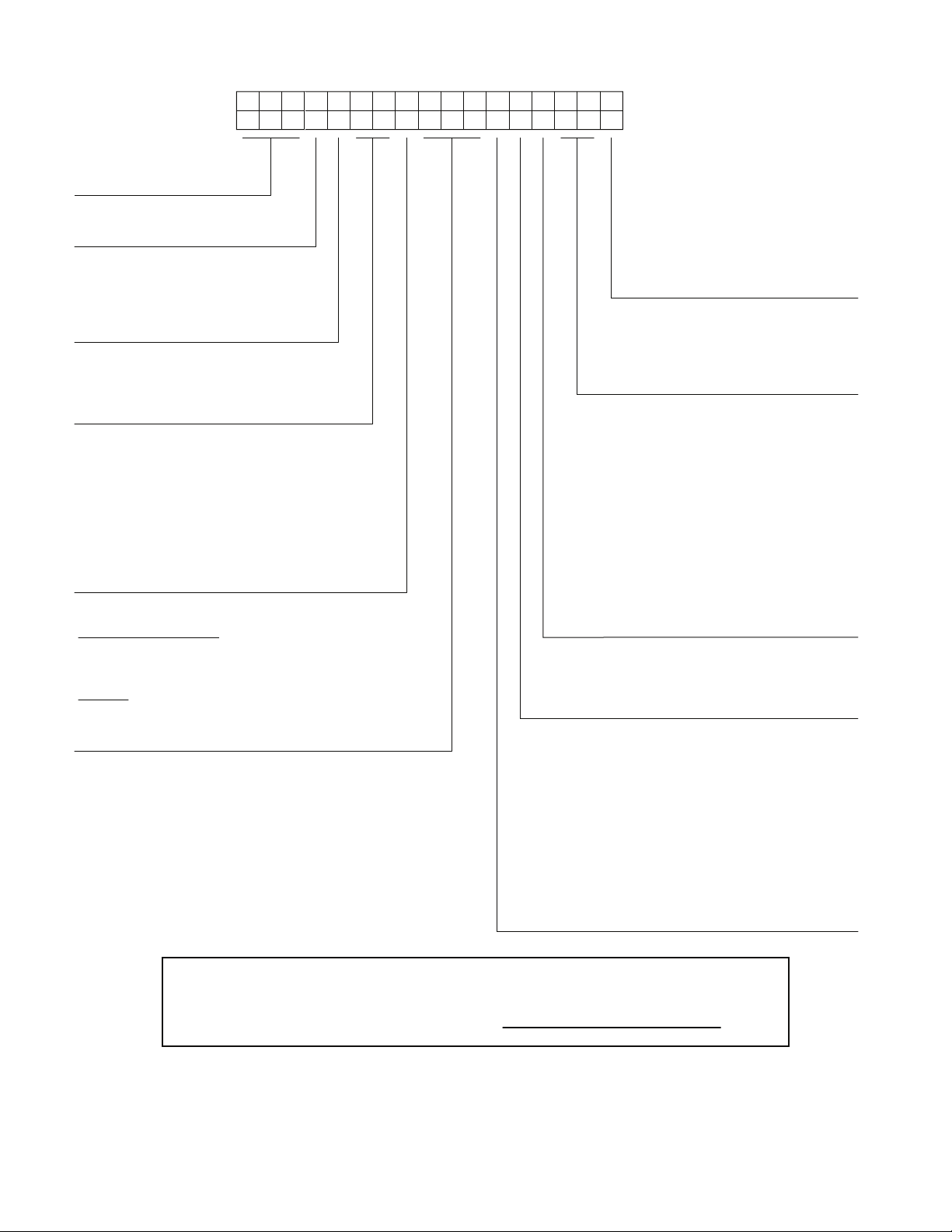
Model
J - Puron
®
(R-410A) Refrigerant
Unit Type
582 - Gas Heat RTU, Legacy Series
Packaging and Control
A = Standard Packaging, electro-mechanical
controls that require W7212 EconoMi$er® IV
B = LTL Packaging
, electro-mechanical
controls that require W7212 EconoMi$er IV
C = Standard Packaging, electro-mechanical
controls that require W7220 EconoMi$er X
F = LTL Packaging, electro-mechanical
controls that require W7220 EconoMi$er X
Cooling Tons
04 - 3 tons
05 - 4 tons
06 - 5 tons
Heat Level Input
Standard / Stainless Steel
072 = 72,000
115 = 115,000
150 = 150,000
Low NOx
060 = 60,000
090 = 90,000
120 = 120,000
Indoor Fan Options
0 = Direct Drive ECM
2 = Medium Static Option
3 = High Static Option
Refrig. System/Gas Heat Options
A = Standard One Stage cooling models/Nat. Gas Heat
B = Standard One Stage cooling models/Low NO
x
Heat
C = Standard One Stage cooling models/SS HX Heat
G = One-Stage cooling models/Alum Heat Exchanger
with Perfect Humidity™
H = One-Stage cooling models/Low NO
x
Heat
with Perfect Humidity
J = One-Stage cooling models/Stainless Steel Exchanger
with Perfect Humidity
Coil Options (RTPF) (Outdoor - Indoor - Hail Guard)
A = Al/Cu - Al/Cu
B = Precoat Al/Cu - Al/Cu
C = E-coat Al/Cu - Al/Cu
D = E-coat Al/Cu - E-coat Al/Cu
E = Cu/Cu - Al/Cu
F = Cu/Cu - Cu/Cu
M = Al/Cu -Al/Cu — Louvered Hail Guard
N = Precoat Al/Cu - Al/Cu — Louvered Hail Guard
P = E-coat Al/Cu - Al/Cu — Louvered Hail Guard
Q = E-coat Al/Cu - E-coat Al/Cu — Louvered Hail Guard
R = Cu/Cu - Al/Cu — Louvered Hail Guard
S = Cu/Cu - Cu/Cu — Louvered Hail Guard
Voltage
E = 460-3-60
J = 208/230-1-60
P = 208/230-3-60
T = 575-3-60
Outdoor Air Options
A = None
B = Temperature Economizer, Barometric Relief,
Standard Leak (W7212 or W7220)
E = Temperature Economizer, Barometric Relief,
Standard Leak w/CO
2
(W7212 or W7220)
H =
Enthalpy
Economizer, Barometric Relief,
Standard Leak (W7212 or W7220)
L =
Enthalpy
Economizer, Barometric Relief,
Standard Leak w/CO
2
(W7212 or W7220)
Q = Motorized 2 Position Damper
U = Temperature
Economizer,
Barometric
Relief,
Ultra Low Leak (W7220)
W =
Enthalpy Economizer,
Barometric
Relief, Ultra Low Leak
(W7220)
Example:
Position:
582JE06A072A0B0A
A
1234567891011 12 13 14 15 16
17
Factory Installed Options
0A = None
NOTE: See the 582J 3 to 5 ton Price Pages
for a complete list of factory installed
options.
Note: On single phase(-J) voltage code) models, the
following are not available as a factory installed option:
- Perfect Humidity
- Coated Coils or Cu Fin Coils
- Louvered Hail Guards
- Economizer or 2 Position Damper
- Powered 115 Volt Convenience Outlet
For California Residents:
For installation in SCAQMD only: This furnace does not meet the SCAQMD Rule 1111 14 ng/J
NOx emission limit, and thus is subject to a mitigation fee of up to $450. This furnace is not
eligible for the Clean Air Furnace Rebate Program: www.CleanAirFurnaceRebate.com.
MODEL NUMBER NOMENCLATURE
\
4
Page 5
®
C
S
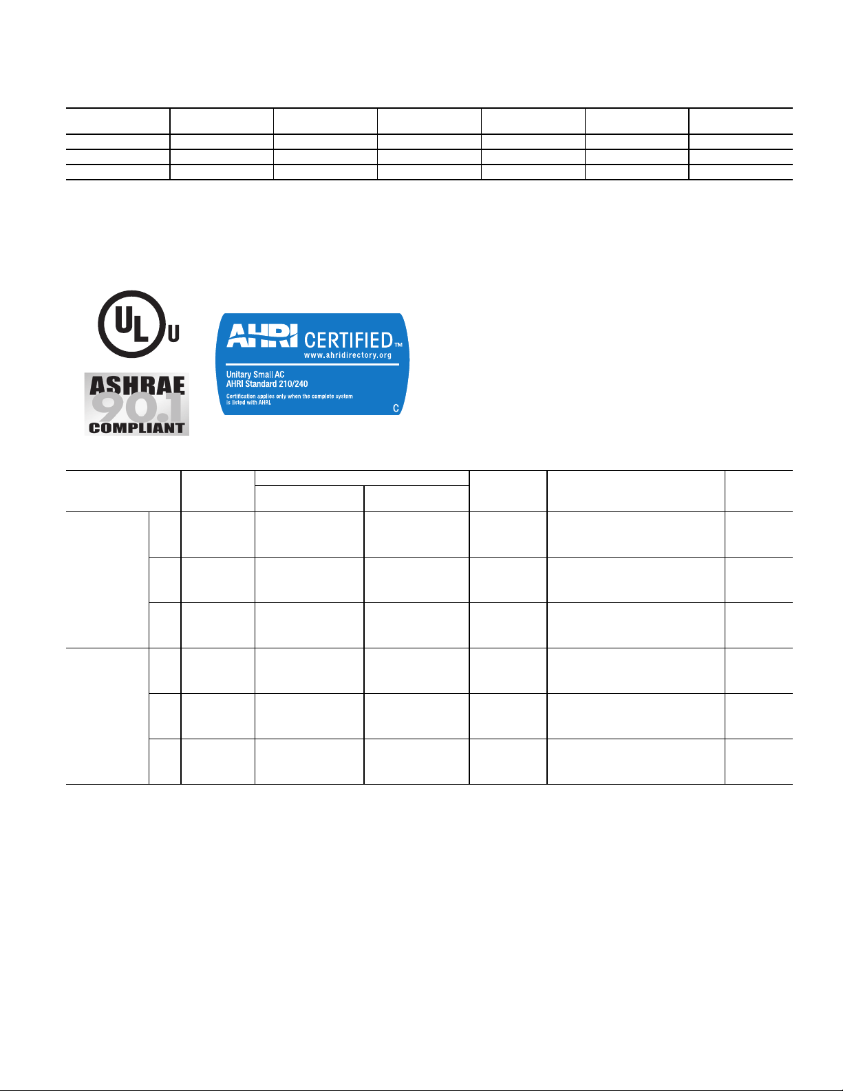
AHRI CAPACITY RATINGS
AHRI COOLING RATING TABLE
UNIT COOLING STAGES
582J*04 1 3 35.4 3.0 14.0 12.00
582J*05 1 4 47.5 4.0 14.0 12.00
582J*06 1 5 58.5 4.9 14.1 12.00
LEGEND NOTES:
AHRI — Air-Conditioning, Heating, and Refrigeration Institute Test
ASHRAE — American Society of Heating, Refrigerating, and Air-Condition-
EER — Energy Efficiency Ratio
SEER — Seasonal Energy Efficiency Ratio
Standard
ing Engineers
NOM. CAPACITY
(TONS)
NET COOLING
CAPACITY (MHBH)
1. Rated in accordance with AHRI Standard 210/240.
2. Ratings are based on:
3. All 582J units comply with ASHRAE 90.1 and Department of Energy
4. All 582J units comply with US Energy Policy Act (2005). To evaluate
TOTAL POWER
(kW)
Cooling Standard: 80°F (27°C) db, 67°F (19°C) wb indoor air temperature and 95°F (35°C) db outdoor air temperature.
(DOE) Energy Standard for minimum SEER and EER requirements.
code compliance requirements, refer to state and local codes.
SEER EER
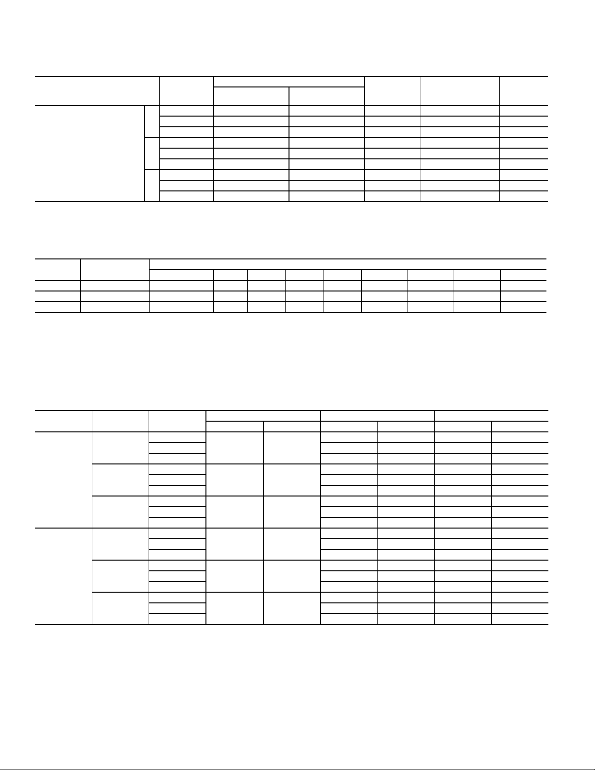
HEATING RATING TABLE - NATURAL GAS AND PROPANE
582J UNITS GAS HEAT
LOW – 65/53 25-55 82.0% 81.0%
04
SINGLE
PHASE
THREE
PHASE
NOTES:
1. Heat ratings are for natural gas heat exchangers operated at or below
2000 ft (610 m). For information on propane or altitudes above 2000 ft
(610 m), see the Application Data section of this book. Accessory Propane/High Altitude kits are also available.
2. In the USA, the input rating for altitudes above 2000 ft (610 m) must be
de-rated by 4% for each 1000 ft (305 m) above sea level. In Canada, the
input rating must be de-rated by 10% for altitudes of 2000 ft (610) to
4500 ft (1372 m) above sea level.
05
06
04
05
06
MED – 90/73.5 45-85 82.0% 81.2%
HIGH – – – – –
LOW – 65/53 20-55 82.0% 81.0%
MED – 90/73.5 30-65 82.0% 81.2%
HIGH – 130/106 45-80 82.0% 81.0%
LOW – 65/53 15-55 82.0% 81.0%
MED – 90/73.5 25-65 82.0% 81.2%
HIGH – 130/106 35-80 82.0% 81.0%
LOW – 72/59 25-55 82.0% N/A
MED 82/66 115/93 55-85 81.0% N/A
HIGH – – – – –
LOW – 72/59 25-55 82.0% N/A
MED – 115/93 35-65 81.0% N/A
HIGH 120/96 150/120 50-80 80.0% N/A
LOW – 72/59 20-55 82.0% N/A
MED – 115/93 30-65 81.0% N/A
HIGH 120/96 150/120 40-80 80.0% N/A
AL/SS HEAT EXCHANGER
INPUT/OUTPUT
STAGE 1 (MBH)
INPUT/OUTPUT
STAGE 2 (MBH)
TEMP RISE
(DEG F)
THERMAL EFFICIENCY (%) AFUE (%)
5
Page 6
AHRI CAPACITY RATINGS (cont)
HEATING RATING TABLE – LOW NOX (see note)
582J UNIT GAS HEAT
LOW — 60/49 20–50 82.0% 81.3%
04
SINGLE/THREE PHASE
— – Not applicable. NOTE: Units meet California’s South Coast Air Quality Management District
05
06
MED — 90/73.5 30–60 82.0% 81.5%
HIGH — — — — —
LOW — 60/49 20–50 82.0% 81.3%
MED — 90/73.5 30–60 82.0% 81.5%
HIGH — 120/98 40–70 82.0% 81.3%
LOW — 60/49 15–50 82.0% 81.3%
MED — 90/73.5 25–60 82.0% 81.5%
HIGH — 120/98 35–70 82.0% 81.3%
LOW NO
INPUT/OUTPUT
STAGE 1 (MBH)
HEAT EXCHANGER
X
INPUT/OUTPUT
STAGE 2 (MBH)
(SCQAQMD) Low - NO
less.
TEMP RISE
(DEG F)
emissions requirement of 40 nanograms per joule or
X
THERMAL
EFFICIENCY (%)
AFUE (%)
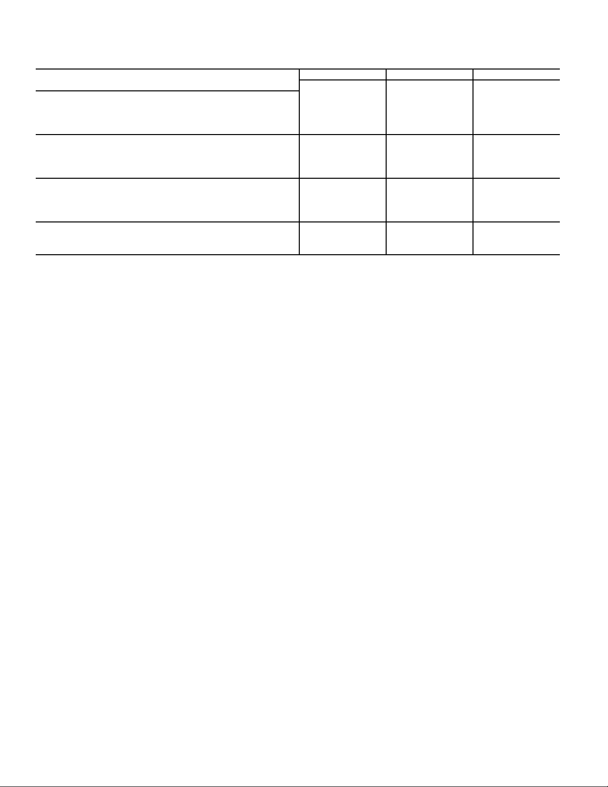
SOUND PERFORMANCE TABLE
582J UNIT
04 A 1 76 78.2 78.0 74.2 73.3 70.6 66.0 62.4 56.9
05 A 1 81 90.9 84.6 79.5 77.9 76.5 71.1 66.9 62.5
06 A 1 77 87.5 82.5 76.1 73.6 71.3 67.1 64.1 60.0
LEGEND
dB – Decibel
NOTES:
1. Outdoor sound data is measured in accordance with AHRI standard 270.
2. Measurements are expressed in terms of sound power. Do not compare these
values to sound pressure values because sound pressure depends on specific
COOLING
STAGES
A–WEIGHTED 63 125 250 500 1000 2000 4000 8000
OUTDOOR SOUND (dB) AT 60 Hz
environmental factors which normally do match individual applications. Sound
power values are independent of the environment and therefore more accurate.
3. A-weighted sound ratings filter out very high and very low frequencies, to
better approximate the response of the “average” human ear. A-weighted measurement for Bryant units are taken in accordance with AHRI standard 270.
MINIMUM - MAXIMUM AIRFLOW RATINGS–NATURAL GAS AND PROPANE
VOLTAGE UNIT HEAT LEVEL
LOW
SINGLE
PHASE
THREE
PHASE
582J*04
582J*05
582J*06
582J*04
582J*05
582J*06
MED 800 1520 800 1520
HIGH ————
LOW
MED 1050 2280 1050 2280
HIGH 1230 2190 1230 2190
LOW
MED 1050 2730 1050 2730
HIGH 1230 2820 1230 2820
LOW
MED 1010 1570 1010 1570
HIGH ————
LOW
MED 1330 2460 1330 2460
HIGH 1390 2220 1390 2220
LOW
MED 1330 2880 1330 2880
HIGH 1390 2780 1390 2780
COOLING AL HX HEATING SS HX HEATING
MINIMUM MAXIMUM MINIMUM MAXIMUM MINIMUM MAXIMUM
900 1970 900 1970
900 1500
900 2470 900 2470
1200 2000
900 3290 900 3290
1500 2500
990 2190 990 2190
900 1500
990 2190 990 2190
1200 2000
990 2730 990 2730
1500 2500
6
Page 7

PHYSICAL DATA
REFERIGERATION SYSTEM
®
Puron
®
Puron
Perfect Humidity™ Puron
EVAPORATION COIL
PERFECT HUMIDITY COIL
EVAP. FAN AND MOTOR
STANDARD STATIC
1 PHASE
MEDIUM STATIC
1 PHASE
HIGH STATIC
1 PHASE
STANDARD STATIC
3 PHASE
MEDIUM STATIC
3 PHASE
HIGH STATIC
3 PHASE
PHYSICAL DATA (COOLING) 3-5 TONS
582J*04A/B 582J*05A/B 582J*06A/B
# Circuits / # Comp. / Type 1 / 1 / Scroll 1 / 1 / Scroll 1 / 1 / Scroll
refrig. (R-410A) A 1 phase (lbs-oz) 7-2 10-8 16-0
refrig. (R-410A) A 3 phase (lbs-oz) 7-2 10-8 14-8
®
refrig. (R-410A) charge A (lbs-oz) 10-6 15-5 26-0
oil A/B (oz) 25 42 42
Metering Device Acutrol Acutrol Acutrol
Perfect Humidity Metering Device Acutrol + TXV Acutrol + TXV Acutrol + TXV
High-press. Trip / Reset (psig) 630/505 630/505 630/505
Low-press. Trip / Reset (psig) 54/117 54/117 54/117
Loss of charge Trip/Reset (psig) N/A N/A N/A
Material (Tube/Fin) Cu/Al Cu/Al Cu/Al
Coil Type
Rows / FPI 3 / 15 3 / 15 4 / 15
Total Face Area (ft
Condensate Drain Conn. Size
Material (Tube/Fin) Cu/Al Cu/Al Cu/Al
Coil Type
Rows / FPI 1 / 17 2 / 17 2 / 17
Total Face Area (ft
Motor Qty / Drive Type 1 / Direct 1 / Direct 1 / Direct
Max BHP111
RPM Range 600-1200 600-1200 600-1200
Motor Frame Size 48 48 48
Fan Qty / Type 1 / Centrifugal 1 / Centrifugal 1 / Centrifugal
Fan Diameter (in.) 10 x 10 10 x 10 10 x 10
Motor Qty / Drive Type 1 / Belt 1 / Belt 1 / Belt
Max BHP 1.2 1.2 1.5
RPM Range 770-1175 770-1175 1035-1466
Motor Frame Size 48 48 56
Fan Qty / Type 1 / Centrifugal 1 / Centrifugal 1 / Centrifugal
Fan Diameter (in.) 10 x 10 10 x 10 10 x 10
Motor Qty / Drive Type 1 / Belt 1 / Belt N/A
Max BHP 1.5 1.5 N/A
RPM Range 1035-1466 1035-1466 N/A
Motor Frame Size 56 56 N/A
Fan Qty / Type 1 / Centrifugal 1 / Centrifugal N/A
Fan Diameter (in.) 10 x 10 10 x 10 N/A
Motor Qty / Drive Type 1 / Direct 1 / Direct 1 / Direct
Max BHP111
RPM Range 600-1200 600-1200 600-1200
Motor Frame Size 48 48 48
Fan Qty / Type 1 / Centrifugal 1 / Centrifugal 1 / Centrifugal
Fan Diameter (in.) 10 x 10 10 x 10 11 x 10
Motor Qty / Drive Type 1 / Belt 1 / Belt 1 / Belt
Max BHP 1.7 1.7 2.9
RPM Range 770-1175 920-1303 1035-1466
Motor Frame Size 48 56 56
Fan Qty / Type 1 / Centrifugal 1 / Centrifugal 1 / Centrifugal
Fan Diameter (in.) 10 x 10 10 x 10 10 x 10
Motor Qty / Drive Type 1 / Belt 1 / Belt 1 / Belt
Max BHP 2.9 2.9 2.9
RPM Range 1035-1466 1208-1550 1303-1550
Motor Frame Size 56 56 56
Fan Qty / Type 1 / Centrifugal 1 / Centrifugal 1 / Centrifugal
Fan Diameter (in.) 10 x 10 10 x 10 10 x 10
3
/8-in. RTPF
2
) 5.5 5.5 7.3
2
) 3.9 3.9 5.2
3
/4-in.
3
/8-in. RTPF
3
/8-in. RTPF
3
/4-in.
3
/8-in. RTPF
3
/8-in. RTPF
3
3
/8-in. RTPF
/4-in.
7
Page 8
PHYSICAL DATA (CONT)
PHYSICAL DATA (COOLING) 3-5 TONS (cont)
582J*04A/B 582J*05A/B 582J*06A/B
COND. COIL
1 phase Material (Tube/Fin) Cu/Al Cu/Al Cu/Al
Coil Type
Rows / FPI 1 / 17 2 / 17 2 / 17
Total Face Area (ft
2
3 phase Material (Tube/Fin)
Coil Type
Rows / FPI 1/17 2/17 2/17
Total Face Area (ft
2
COND. FAN / MOTOR
Qty / Motor Drive Type 1 / Direct 1 / Direct 1 / Direct
Motor HP / RPM 1 / 8 / 825 1 / 4 / 1100 1 / 4 / 1100
Fan diameter (in.) 22 22 22
FILTERS
RA Filter # / Size (in.) 2 / 16 x 25 x 2 2 / 16 x 25 x 2 4 / 16 x 16 x 2
OA inlet screen # / Size (in.) 1 / 20 x 24 x 1 1 / 20 x 24 x 1 1 / 20 x 24 x 1
N/A – Not applicable
3
/8-in. RTPF
3
/8-in. RTPF
3
/8-in. RTPF
) 16.5 16.5 21.3
3
/8-in. RTPF
3
/8-in. RTPF
3
/8-in. RTPF
) 16.5 14.6 18.8
8
Page 9

PHYSICAL DATA (HEATING - SINGLE PHASE UNITS) 3-5 TONS
ELECTRICAL
GAS CONNECTION
Nat. gas supply line pressure (in. wg) / (PSIG) 4-13 / 0.18-0.47 4-13 / 0.18-0.47 4-13 / 0.18-0.47
LP gas supply line pressure (in. wg) / (PSIG) 11-13 / 0.40-0.47 11-13 / 0.40-0.47 11-13 / 0.40-0.47
HEAT ANTICIPATOR SETTING (AMPS)
NATURAL GAS HEAT
# of stages / # of burners (total) 1 / 2 1 / 2 1 / 2
LOW
MED
HIGH
LIQUID PROPANE HEAT
LOW
MED
HIGH
LOW NOX GAS HEAT
LOW
MED
HIGH
LEGEND
LP – Liquid propane
— – Not applicable
Rollout switch opens/closes (°F) 195 / 115 195 / 115 195 / 115
# of stages / # of burners (total) 1 or 2 / 3 1 / 3 1 / 3
Rollout switch opens/closes (°F) 195 / 115 195 / 115 195 / 115
# of stages / # of burners (total) — 1 or 2 / 3 1 or 2 / 3
Rollout switch opens/closes (°F) — 195 / 115 195 / 115
# of stages / # of burners (total) 1 / 2 1 / 2 1 / 2
Rollout switch opens/closes (°F) 195 / 115 195 / 115 195 / 115
# of stages / # of burners (total) 1 / 3 1 / 3 1 / 3
Rollout switch opens/closes (°F) 195 / 115 195 / 115 195 / 115
# of stages / # of burners (total) — 1 / 3 1 / 3
Rollout switch opens/closes (°F) — 195 / 115 195 / 115
582J*04 582J*05 582J*06
Single Phase Single Phase Single Phase
# of Gas valves 1 1 1
First stage 0.14 0.14 0.14
Second stage 0.14 0.14 0.14
Connection size
1
/2-in. NPT
1
/2-in. NPT
1
/2-in. NPT
Temperature rise (°F) 25-55 20-55 15-55
Connection size
1
/2-in. NPT
1
/2-in. NPT
1
/2-in. NPT
Temperature rise (°F) 45-85 30-65 25-65
Connection size —
1
/2-in. NPT
1
/2-in. NPT
Temperature rise (°F) — 45-80 35-80
Connection size
1
/2-in. NPT
1
/2-in. NPT
1
/2-in. NPT
Temperature rise (°F) 25-55 20-55 15-55
Connection Size
1
/2-in. NPT
1
/2-in. NPT
1
/2-in. NPT
Temperature Rise (°F) 45-85 30-65 25-65
Connection size —
1
/2-in. NPT
1
/2-in. NPT
Temperature rise (°F) — 45-80 35-80
Connection size
1
/2-in. NPT
1
/2-in. NPT
1
/2-in. NPT
Temperature rise (°F) 20-50 20-50 15-50
Connection size
1
/2-in. NPT
1
/2-in. NPT
1
/2-in. NPT
Temperature rise (°F) 30-60 30-60 25-60
Connection size —
1
/2-in. NPT
1
/2-in. NPT
Temperature rise (°F) — 40-70 35-70
9
Page 10

PHYSICAL DATA (CONT)
PHYSICAL DATA (HEATING - THREE PHASE UNITS) 3-5 TONS
ELECTRICAL
GAS CONNECTION
# of Gas valves 1 1 1
Nat. gas supply line pressure (in. wg.) / (PSIG) 4-13 / 0.18-0.47 4-13 / 0.18-0.47 4-13 / 0.18-0.47
LP gas supply line pressure (in. wg.) / (PSIG) 11-13 / 0.40-0.47 11-13 / 0.40-0.47 11-13 / 0.40-0.47
HEAT ANTICIPATOR SETTING (AMPS)
First stage 0.14 0.14 0.14
Second stage 0.14 0.14 0.14
NATURAL GAS HEAT
# of stages / # of burners (total) 1 / 2 1 / 2 1 / 2
LOW
MED
HIGH
LIQUID PROPANE HEAT
LOW
MED
HIGH
LOW NOX GAS HEAT
LOW
MED
HIGH
LEGEND
LP – Liquid propane
— – Not applicable
Rollout switch opens/closes (°F) 195 / 115 195 / 115 195 / 115
# of stages / # of burners (total) 1 or 2 / 3 1 / 3 1 / 3
Rollout switch opens/closes (°F) 195 / 115 195 / 115 195 / 115
# of stages / # of burners (total) — 1 or 2 / 3 1 or 2 / 3
Rollout switch opens/closes (°F) — 195 / 115 195 / 115
# of stages / # of burners (total) 1 / 2 1 / 2 1 / 2
Rollout switch opens/closes (°F) 195 / 115 195 / 115 195 / 115
# of stages / # of burners (total) 1 or 2 / 3 1 / 3 1 / 3
Rollout switch opens/closes (°F) 195 / 115 195 / 115 195 / 115
# of stages / # of burners (total) — 1 or 2 / 3 1 or 2 / 3
Rollout switch opens/closes (°F) — 195 / 115 195 / 115
# of stages / # of burners (total) 1 / 2 1 / 2 1 / 2
Rollout switch opens/closes (°F) 195 / 115 195 / 115 195 / 115
# of stages / # of burners (total) 1 / 3 1 / 3 1 / 3
Rollout switch opens/closes (°F) 195 / 115 195 / 115 195 / 115
# of stages / # of burners (total) — 1 / 3 1 / 3
Rollout switch opens/closes (°F) — 195 / 115 195 / 115
Connection size
Temperature rise (°F) 25-55 25-55 20-55
Connection size
Temperature rise (°F) 55-85 35-65 30-65
Connection size —
Temperature rise (°F) — 50-80 40-80
Connection size
Temperature rise (°F) 25-55 25-55 20-55
Connection size
Temperature rise (°F) 55-85 35-65 30-65
Connection size —
Temperature rise (°F) — 50-80 40-80
Connection size
Temperature rise (°F) 20-50 20-50 15-50
Connection size
Temperature rise (°F) 30-60 30-60 25-60
Connection size —
Temperature rise (°F) — 40-70 35-70
582J*04 582J*05 582J*06
Three Phase Three Phase Three Phase
1
/2-in. NPT
1
/2-in. NPT
1
/2-in. NPT
1
/2-in. NPT
1
/2-in. NPT
1
/2-in. NPT
1
/2-in. NPT
1
/2-in. NPT
1
/2-in. NPT
1
/2-in. NPT
1
/2-in. NPT
1
/2-in. NPT
1
/2-in. NPT
1
/2-in. NPT
1
/2-in. NPT
1
/2-in. NPT
1
/2-in. NPT
1
/2-in. NPT
1
/2-in. NPT
1
/2-in. NPT
1
/2-in. NPT
1
/2-in. NPT
1
/2-in. NPT
1
/2-in. NPT
10
Page 11
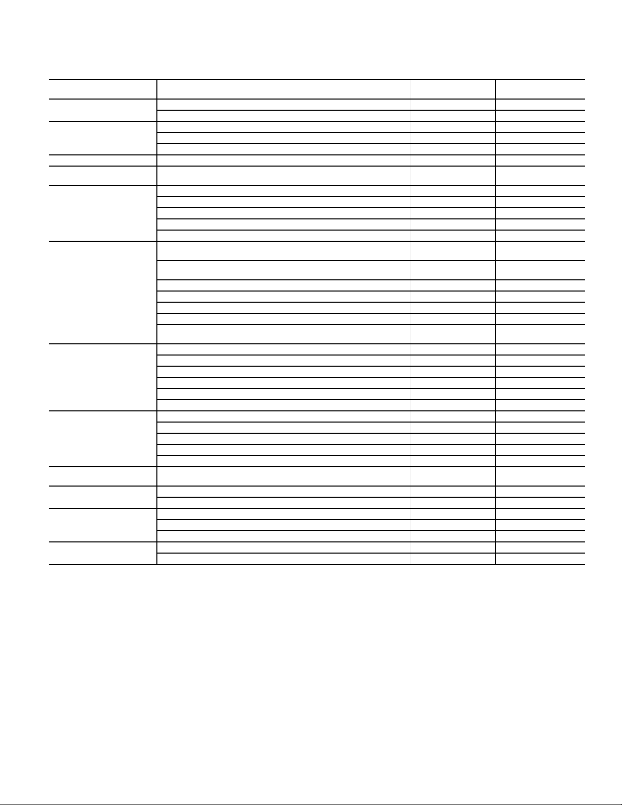
OPTIONS AND ACCESSORIES
CATEGORY ITEM
CABINET
COIL OPTIONS
Thru-the-base electrical or gas-line connections X X
Hinged Access Panels X
Cu/Cu indoor and/or outdoor coils
Pre-coated outdoor coils
Premium, E-coated outdoor coils
5
5
5
HUMIDITY CONTROL Perfect Humidity™ Dehumidification System
CONDENSER
PROTECTION
Condenser coil hail guard (louvered design)
5
5
FACTORY-
INSTALLED OPTION
X
X
X
X
XX
Thermostats, temperature sensors, and subbases X
RTU Open multi-protocol controller X
CONTROLS
Smoke detector (supply and/or return air) X
Time Guard II compressor delay control circuit X
Phase Monitor X
ECONOMIZERS AND
OUTDOOR AIR DAMPERS
EconoMi$er IV for electro-mechnical controls - Non FDD (Standard
air leak damper models)
EconoMi$er2 for DDC controls, complies with FDD (Standard and
Ultra Low Leak air damper models)
Motorized 2-position outdoor air damper
5, 6
5, 7
5
Manual outdoor air damper (25% and 50%) X
Barometric relief
1
XX
XX
XX
XX
Power exhaust X
ECONOMIZER SENSORS
AND IAQ DEVICES
EconoMi$er X for electro-mechanical controls, complies with FDD.
(Standard and Ultra Low Leak air damper models)
Single dry bulb temperature sensors
Differential dry bulb temperature sensors
sensor
2
2
2
sensor
2
2
Single enthalpy sensors
Differential enthalpy sensors
Wall-mounted or duct-mounted CO
Unit-mounted CO
5, 6
2
2
2
XX
XX
XX
X
Propane conversion kit X
Stainless steel heat exchanger X
GAS HEAT
High altitude conversion kit X
Flue Shield X
Flue Discharge Deflector X
INDOOR MOTOR AND
DRIVE
LOW AMBIENT CONTROL
POWER OPTIONS
ROOF CURBS
Multiple motor and drive packages X
Winter start kit
Motormaster
®
head pressure controller
Convenience outlet (powered)
3
3
5
X
Convenience outlet (non-powered) X
Non-fused disconnect
4
X
Roof curb 14-in. (356mm) X
Roof curb 24-in. (610mm) X
NOTES:
1. Included with economizer.
2. Sensors used to optimize economizer performance.
3. See application data for assistance.
4. Available on units with MOCPs of 80 amps or less.
5. Not available as factory-installed option on single phase (208-230/1/60) models. Use field-installed accessory where available.
6. FDD (Fault Detection and Diagnostic) capability per California Title 24 section 120.2.
7. Models with RTU Open DDC controls comply with California Title 24 Fault Detection and Diagnostic (FDD).
FIELD-INSTALLED
ACCESSORY
X
X
X
X
X
11
Page 12

OPTIONS AND ACCESSORIES (CONT)
Economizer
Economizers save energy, money and improve comfort levels
in the conditioned space. They bring in fresh, outside air for
ventilation; and provide cool outside air to cool your building.
This is also the preferred method of low ambient cooling.
When integrated with CO
sensors, economizers can provide
2
even more savings by coupling the ventilation air to only the
amount required based on space occupancy. Economizers are
available, installed and tested by the factory, with either
enthalpy or temperature dry-bulb inputs. There are also models
for electromechanical and direct digital controllers. Additional
sensors are available as accessories to optimize the economizer.
Economizers include gravity controlled barometric relief that
helps equalize building pressure and ambient air pressures.
This can be a cost effective solution to prevent building pressurization. Economizers are available in Ultra Low Leak and
standard low leak versions.
CO2 sensor
CO2 sensors improve productivity and save money by working
with the economizer to intake the correct amount of outside air
for ventilation. As occupants fill your building, the CO
detects their presence through increasing CO
levels and opens
2
sensor
2
the economizer appropriately.
When the occupants leave, the CO
levels decrease, and the
2
sensor appropriately closes the economizer. This intelligent
control of the ventilation air, called Demand Controlled Ventilation (DCV) reduces the overall load on the rooftop, saving
money.
Smoke detectors
Trust the experts. Smoke detectors make your application safer
and your job easier. Bryant smoke detectors immediately shut
down the rooftop unit when smoke is detected. They are available, installed by the factory, for supply air, return air, or both.
Louvered hail guards
Sleek, louvered panels protect the condenser coil from hail
damage, foreign objects, and incidental contact.
Convenience outlet (powered or un-powered)
Reduce service and/or installation costs by including a convenience outlet in your specification. Bryant will install this service feature at our factory. It provides a convenient, 15 amp,
115v GFCI receptacle with “Wet in Use” cover. The “powered”
option allows the installer to power the outlet from the line side
of the disconnect or load side as required by code. The “unpowered” option is to be powered from a separate 115/120-v
power source.
Non-fused disconnect
This OSHA-compliant, factory-installed safety switch allows a
service technician to locally secure power to the rooftop.
Power exhaust with barometric relief
Superior internal building pressure control. This field-installed
accessory may eliminate the need for costly, external pressure
control fans.
RTU Open, multi-protocol controller
Connect the rooftop to an existing BAS without needing complicated translators or adapter modules using the RTU Open
controller. This new controller speaks the 4 most common
building automation system languages (BACnet
N2, and LonWorks
3
). Use this controller when you have an
1
, Modbus2,
existing BAS.
Time Guard II control circuit
This accessory protects your compressor by preventing shortcycling in the event of some other failure and prevents the compressor from restarting for 30 seconds after stopping. Not
required with RTU Open or authorized commercial thermostats.
Motorized 2-position damper
The new Bryant 2-position, motorized outdoor air damper
admits up to 100% outside air. Using reliable, gear-driven technology, the 2-position damper opens to allow ventilation air and
closes when the rooftop stops, stopping unwanted infiltration.
Manual OA damper
Manual outdoor air dampers are an economical way to bring in
ventilation air. The dampers are available in 25% and 50%
versions.
Optional Perfect Humidity™ dehumidification system
Bryant’s Perfect Humidity dehumidification system is an allinclusive factory-installed option that can be ordered with any
Legacy Line 582J*04-06B rooftop unit.
This system expands the envelope of operation of Bryant’s
Legacy Line rooftop products to provide unprecedented flexibility to meet year-round comfort conditions.
The Perfect Humidity dehumidification system has the industry’s only dual dehumidification mode setting. The Perfect
Humidity system includes two new modes of operation.
The Legacy Line 582J*04-06B rooftop coupled with the Perfect Humidity system is capable of operating in normal design
cooling mode, subcooling mode, and hot gas reheat mode. Normal design cooling mode is when the unit will operate under its
normal sequence of operation by cycling compressors to maintain comfort conditions.
Subcooling mode will operate to satisfy part load type conditions when the space requires combined sensible and a higher
proportion of latent load control. Hot Gas Reheat mode will
operate when outdoor temperatures diminish and the need for
latent capacity is required for sole humidity control. Hot Gas
Reheat mode will provide neutral air for maximum dehumidification operation.
Motormaster® head pressure controller
The Motormaster motor controller is a low ambient, head pressure
controller kit that is designed to maintain the unit’s condenser head
pressure during periods of low ambient cooling operation. This
device should be used as an alternative to economizer free cooling
when economizer usage is either not appropriate or desired. The
Motormaster will either cycle the outdoor fan motors or operate
them at reduced speed to maintain the unit operation, depending
on the model.
12
1. BACnet is a registered trademark of ASHRAE (American Society of
Heating, Refrigerating, and Air-Conditioning Engineers).
2. Modbus is a registered trademark of Schneider Electric.
3. LonWorks is a registered trademark of Echelon Corporation.
Page 13

Winter start kit
The winter start kit by Bryant extends the low ambient limit of
your rooftop to 25°F (–4°C). The kit bypasses the low pressure
switch, preventing nuisance tripping of the low pressure
switch. Other low ambient precautions may still be prudent.
Propane heating
Convert your gas heat rooftop from standard natural gas operation to propane using this field-installed kit.
High altitude heating
High altitudes have less oxygen, which means heat exchangers
need less fuel. The new gas orifices in this field-installed kit
make the necessary adjustment for high altitude applications.
They restore the optimal fuel to air mixture and maintain
healthy combustion at altitudes above 2000 ft (610m). Kits
may not be required in all areas.
Hinged access panels
Allows access to unit’s major components with specifically
designed hinged access panels. Panels are: filter, control box,
fan motor, and compressor.
Flue discharge deflector
The flue discharge deflector is a useful accessory when flue gas
recirculation is a concern. By venting the flue discharge
upwards, the deflector minimizes the chance for a neighboring
unit to intake the flue exhaust.
Optional stainless steel heat exchanger
The stainless steel heat exchanger option provides the tubular
heat exchanger made out of a minimum 20 gage type 409 stainless steel for applications where the mixed air to the heat
exchanger is expected to drop below 45°F (7°C). Stainless steel
may be specified on applications where the presence of airborne contaminants require its use (applications such as paper
mills) or in areas with very high outdoor humidity that may
result in severe condensation in the heat exchanger during cooling operation.
Flue discharge heat shield
The flue discharge heat shield keeps people from touching the
rooftop unit’s potentially hot flue discharge. This is especially
useful for ground level applications, where more untrained
people could have access to the unit’s exterior.
Alternate motors and drives
Some applications need larger horsepower motors, some need
more airflow, and some need both. Regardless of the case, your
Bryant expert has a factory-installed combination to meet your
application. A wide selection of motors and pulleys (drives) are
available, factory installed, to handle nearly any application.
Thru-the-base connections
Thru-the-base connections, available as either an accessory or
as a factory option, are necessary to ensure proper connection
and seal when routing wire and piping through the rooftop’s
basepan and curb. These couplings eliminate roof penetration
and should be considered for gas lines, main power lines, as
well as control power.
13
Page 14
OPTIONS AND ACCESSORIES (CONT)
OPTIONS AND ACCESSORY WEIGHTS
OPTION/ACESSORY WEIGHTS
OPTION/ACCESSORY
Perfect Humidity™
1
Power exhaust - vertical 45 20 45 20 45 20
Power exhaust - horizontal 30 14 30 14 30 14
EconoMi$er (IV, X, or 2) 35 16 35 16 35 16
Two-position damper 39 18 39 18 39 18
Manual dampers 12 5 12 5 12 5
Medium gas heat 12 59494
High gas heat ——178178
Hail guard (louvered) 13 6 13 6 17 8
Cu/Cu Condenser Coil
Cu/Cu Condenser and Evaporator Coils
2
2
Roof curb (14-in. curb) 115 52 115 52 115 52
Roof curb (24-in. curb) 197 89 197 89 197 89
CO
sensor 212121
2
Flue discharge deflector 737373
Optional indoor motor/drive 6 3 6 3 17 8
Motormaster controller 949494
Return smoke detector 737373
Supply smoke detector 7 37373
Non-fused disconnect 5 25252
Powered convenience outlet 36 16 36 16 36 16
Non-powered convenience outlet 424242
Enthalpy sensor 212121
Differential enthalpy sensor 313131
NOTE: Where multiple variations are available, the heaviest combination is listed.
— Not available
1
For Perfect Humidity, add Motormaster® Controller.
2
Where available.
04 05 06
lb kg lb kg lb kg
50 23 50 23 55 25
37 17 74 34 95 43
75 34 112 51 165 75
14
Page 15
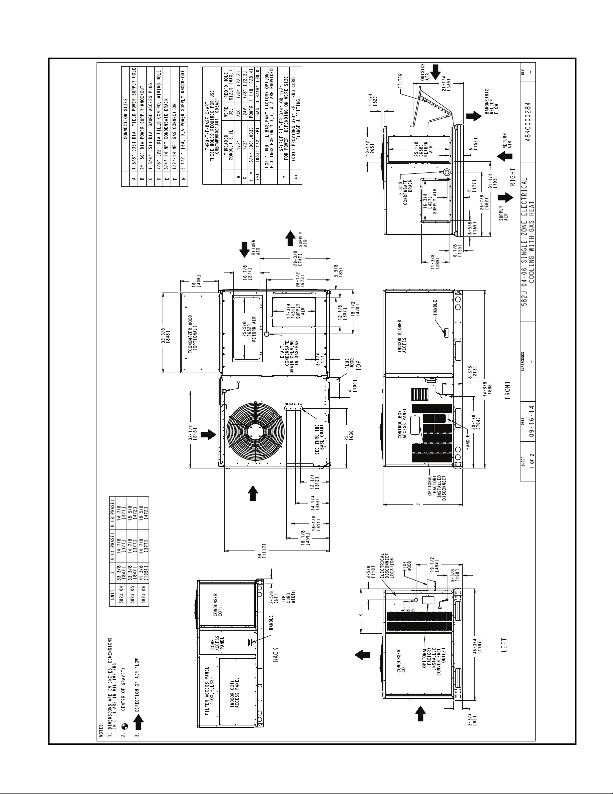
582J*04-06 BASE UNIT DIMENSIONS
BASE UNIT DIMENSIONS
15
Page 16
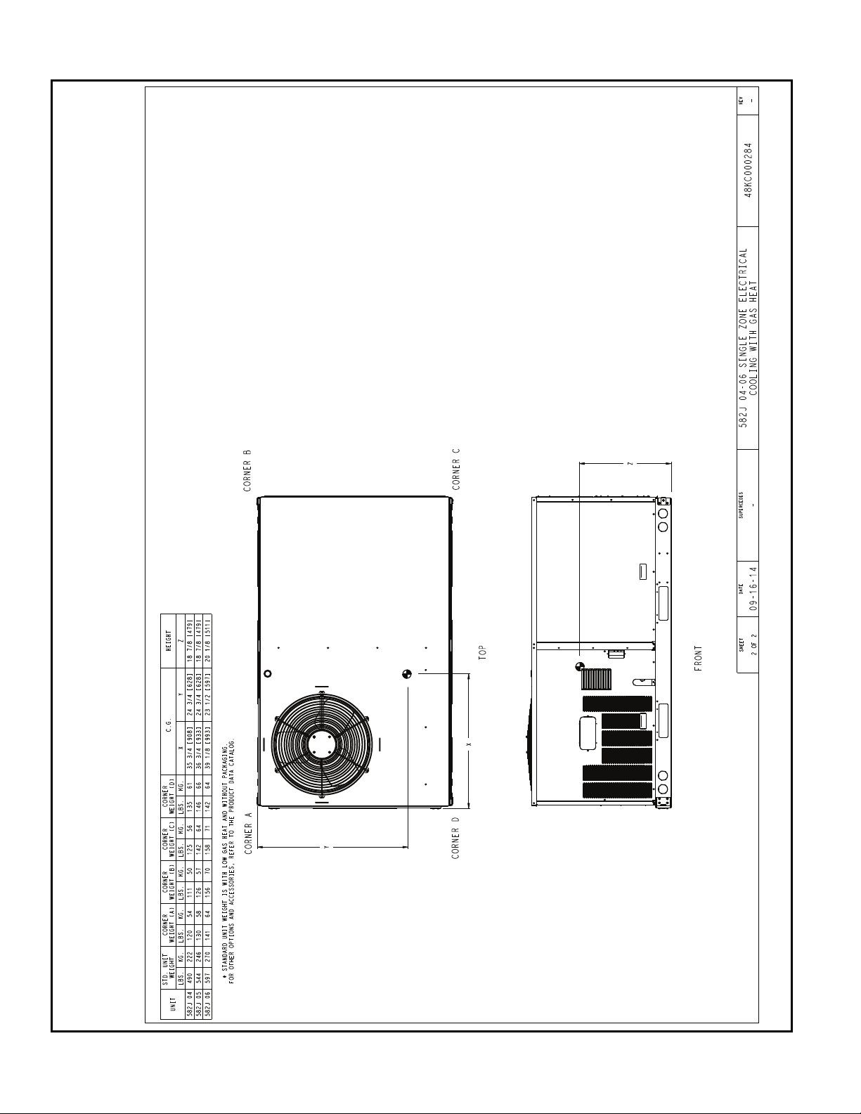
582J*04-06 CORNER WEIGHTS
BASE UNIT DIMENSIONS (CONT)
16
Page 17
C
B
A
D
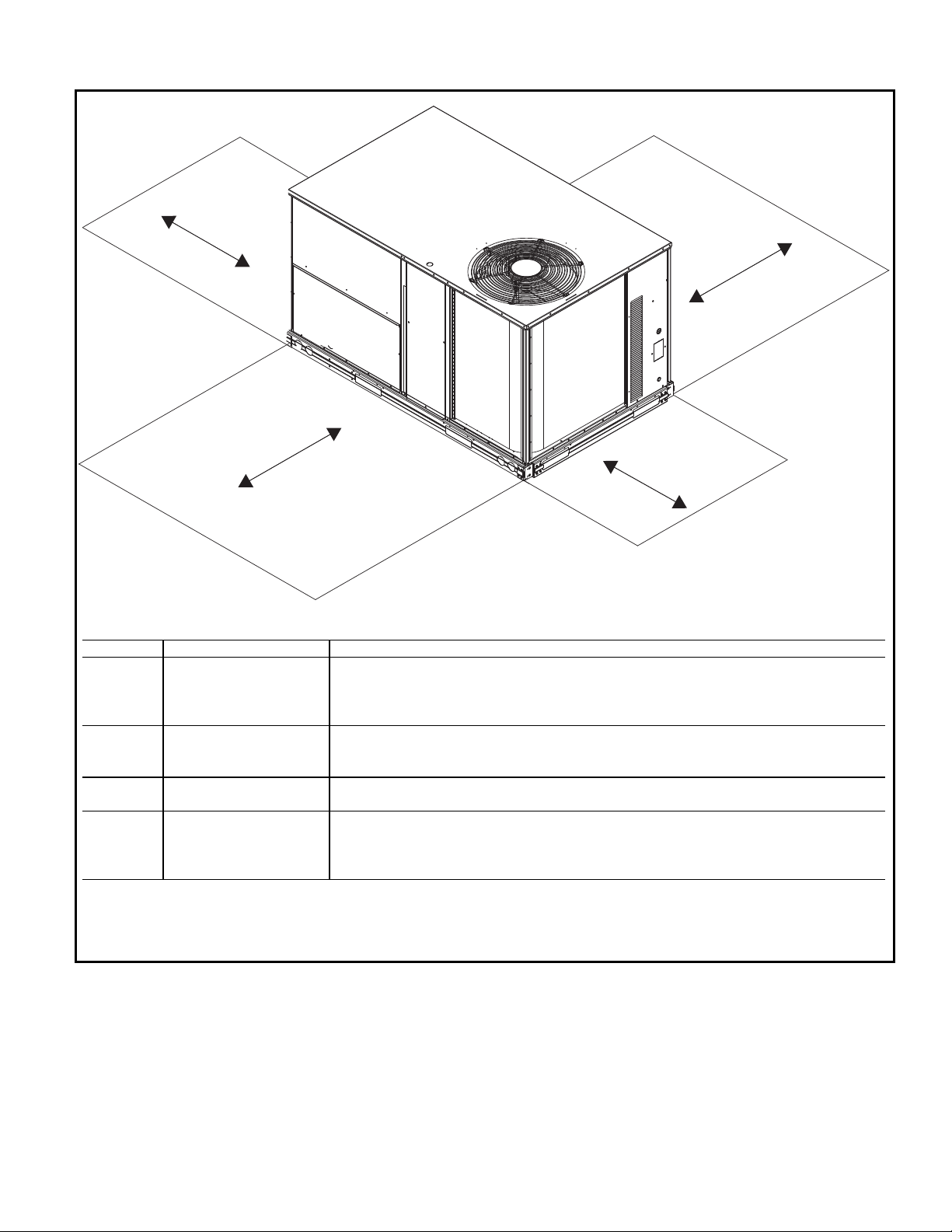
NOTE: Unit not designed to have overhead obstruction. Contact Application Engineering for guidance on any application planning overhead obstruction or for vertical clearances.
SERVICE CLEARANCE DIMENSIONS
LOCATION DIMENSION CONDITION
A
48-in. (1219 mm) Unit disconnect is mounted on panel
18-in. (457 mm) No disconnect, convenience outlet option
18-in. (457 mm) Recommended service clearance
12-in. (305 mm) Minimum clearance
B
42-in. (1067 mm) Surface behind servicer is grounded (e.g., metal, masonry wall)
36-in. (914 mm) Surface behind servicer is electrically non-conductive (e.g., wood, fiberglass)
Special Check sources of flue products within 10 ft (3 m) of unit fresh air intake hood
C
36-in. (914 mm) Side condensate drain is used
18-in. (457 mm) Minimum clearance
D
48-in. (1219 mm) No flue discharge accessory installed, surface is combustible material
42-in. (1067 mm) Surface behind servicer is grounded (e.g., metal, masonry wall, another unit)
36-in. (914 mm) Surface behind servicer is electrically non-conductive (e.g., wood, fiberglass)
Special Check for adjacent units or building fresh air intakes within 10 ft (3 m) of this unit’s flue outlet
17
Page 18

E
E
7/16"
[11]
4 9/16"
[115.5]
1/4"
[7.0]
5' 7-3/8"
[1711.3]
1' 4-13/16"
[427] INSIDE
1-3/4"
[44.4]
2-3/8"
[61]
1-3/4"
[44.5]
1.00"
[25.4]
"A"
1-3/4"
[44.4]
21.74"
[552.2]
5.42"
[137.7]
11.96"
[303.8]
4.96"
[126.0]
70.87"
[1800.2]
40.69"
[1033.5]
21.84"
[554.7]
16.03"
[407.2]
1.75"
[44.5]
20.41"
[518.3]
3.00"
[76.2]
13.78"
[350.0]
14.00"
[355.6]
3.00"
[76.2]
15.19"
[385.8]
32.19"
[817.6]
3'-1 3/16"
[944.6]
"A"
1-3/4"
[44.5]
CRBTMPWR001A01 3/4" [19] NPT
3/4" [19] NPT
1/2" [12.7] NPTCRRFCURB002A01
CONNECTOR PKG. ACC. GAS CONNECTION TYPE GAS FITTING
POWER WIRING
FITTING
CONTROL WIRING
FITTING
ACCESSORY CONVENIENCE
OUTLET WIRING CONNECTOR
THRU THE CURB
1/2" [12.7] NPT 1/2" [12.7] NPT
CRBTMPWR003A01 THRU THE BOTTOM
ROOF CURB
ACCESSORY #
A
CRRFCURB001A01
14"
[356]
24"
[610]
ECN NO.APP'DCHK'DBYDATEREVISION RECORDREV
1067898--MMC04/22/13
OVERALL DIM. 5'-7 3/8" WAS 5'-7 7/8; 18GA
MATERIAL WA 16 GA.; NAIL FIELD SUPPLIED WAS
WITH CURB
A
DRAWING RELEASE LEVEL:
PRODUCTION
INDIANAPOLIS, IN.
SYRACUSE, NY.
THIRD ANGLE
PROJECTION
UNLESS OTHERWISE SPECIFIED
DIMENSIONS ARE IN INCHES
TOLERANCES ON:
THIS DOCUMENT AND THE INFORMATION CONTAINED THEREIN
IS PROPRIETARY TO CARRIER CORPORATION AND SHALL NOT
BE USED OR DISCLOSED TO OTHERS, IN WHOLE OR IN PART,
WITHOUT THE WRITTEN AUTHORIZATION OF CARRIER CORPORATION.
1 DEC 2 DEC 3 DEC ANG
MATERIAL
- - - -
---
AUTHORIZATION NUMBER TITLE
1041738
CURB ASY, ROOF
ENGINEERING MANUFACTURING
(004-007)
ENGINEERING REQUIREMENTS
-
-
-
-
SIZE DRAWING NUMBER REV
T-005, Y-002
DRAFTER CHECKER
D
48TC400427
B
WEIGHT:
-
MMC 06/17/11 - -
SHEET 5 OF 5
SURFACE FINISH MFG/PURCH MODEL (INTERNAL USE ONLY) NEXT DRAWING SCALE DISTRIBUTION
- PURCH - N/A MMC
NOTES:
1. ROOFCURB ACCESSORY IS SHIPPED DISASSEMBLED.
2. INSULATED PANELS: 25.4 [1"] THK. POLYURETHANE FOAM, 44.5 [1-3/4] # DENSITY.
3. DIMENSIONS IN [ ] ARE IN MILLIMETERS.
4. ROOFCURB: 18 GAGE STEEL.
5. ATTACH DUCTWORK TO CURB. (FLANGES OF DUCT REST ON CURB).
6. SERVICE CLEARANCE 4 FEET ON EACH SIDE.
7. DIRECTION OF AIR FLOW.
8. CONNECTOR PACKAGE CRBTMPWR001A01 IS FOR THRU-THE-CURB GAS TYPE
PACKAGE CRBTMPWR003A01 IS FOR THRU-THE-BOTTOM TYPE GAS CONNECTIONS.
TYPICAL (4) SIDES
SUPPLY AIR RETURN AIR
ROOFING MATERIAL
(FIELD SUPPLIED)
CANT STRIP
(FIELD SUPPLIED)
ROOFING FELT
(FIELD SUPPLIED)
COUNTER FLASHING
(FIELD SUPPLIED)
UNIT
GASKET
(SUPPLIED WITH CURB)
RIGID INSULATION
(FIELD SUPPLIED)
DUCT
(FIELD SUPPLIED)
NAIL (FIELD SUPPLIED)
CERTIFIED DRAWING
VIEW "B"
CORNER DETAIL
SEE VIEW "B"
RETURN AIR
SUPPLY AIR
SUPPLY AIR
OPENING
RETURN AIR
OPENING
GAS SERVICE PLATE
THRU THE CURB
DRILL HOLE
2" [50.8] @
ASSEMBLY (IF
REQUIRED)
(SEE NOTE #8)
SEE NOTE #2
11 3/4"[298.5] WIDE
INSULATED DECK PANELS
8 9/16"[217.5] WIDE
INSULATED DECK PANEL
1/3/4"[44.5]
SCALE 0.250
E-ESECTION
ROOF DETAILS 582J*04-06
BASE UNIT DIMENSIONS (CONT)
18
Page 19

APPLICATION DATA
Rather than oversizing an air conditioner, engineers should
“right size” or even slightly undersize air conditioners. Correctly sizing an air conditioner controls humidity better, promotes efficiency, reduces utility bills, extends equipment life,
and maintains even, comfortable temperatures. Please contact
your local Bryant representative for assistance.
Min operating ambient temp (cooling)
In mechanical cooling mode, your Bryant rooftop unit can
safely operate down to an outdoor ambient temperature of 40°F
(4°C) and 25°F (–4°C), with an accessory winter start kit. It is
possible to provide cooling at lower outdoor ambient temperatures by using less outside air, economizers, and/or accessory
low ambient kits.
Max operating ambient temp (cooling)
The maximum operating ambient temperature for cooling
mode is 115°F (46°C). While cooling operation above 115°F
(46°C) may be possible, it could cause either a reduction in performance, reliability, or a protective action by the unit’s internal safety devices.
Min mixed air temp (heating)
Using the factory settings, the minimum temperatures for the
mixed air (the combined temperature of the warm return air and
the cold outdoor air) entering the dimpled, gas heat exchangers
are:
ALUMINIZED STAINLESS STEEL
50°F (10°C) continuous 40°F (4°C) continuous
45°F (7°C) intermittent 35°F (2°C) intermittent
Operating at lower mixed-air temperatures may be possible, if a
field-supplied, outdoor air thermostat initiates both heat stages
when the temperature is less than the minimum temperatures
listed above. Please contact your local Bryant representative
for assistance.
Min and max airflow (heating and cooling)
To maintain safe and reliable operation of your rooftop, operate
within the heating airflow limits during heating mode and cooling airflow limits during cooling mode. Operating above the
max may cause blow-off, undesired airflow noise, or airflow
related problems with the rooftop unit. Operating below the
min may cause problems with coil freeze-up and unsafe heating
operation. Heating and cooling limitations differ when evaluating operating cfm, the minimum value is the HIGHER of the
cooling and heating minimum cfm values published in “Minimum - Maximum Airflow Ratings–Natural Gas and Propane”
on page 6 and the maximum value is the LOWER of the cooling and heating maximum values published in “Minimum Maximum Airflow Ratings–Natural Gas and Propane” on
page 6.
Heating-to-cooling changeover
Your unit will automatically change from heating to cooling
mode when using a thermostat with an auto-changeover feature.
Airflow
All units are draw-through in cooling mode and blow-through
in heating mode.
Outdoor air application strategies
Economizers reduce operating expenses and compressor run
time by providing a free source of cooling and a means of ventilation to match application changing needs. In fact, they
should be considered for most applications. Also, consider the
various economizer control methods and their benefits, as well
as sensors required to accomplish your application goals.
Please contact your local Bryant representative for assistance.
Motor limits, Brake horsepower (BHP):
Due to internal design of Bryant units, the air path, and specially
designed motors, the full horsepower (maximum continuous
BHP) band, as listed in “PHYSICAL DATA (Cooling) 3-5 Tons”
on page 7, can be used with the utmost confidence. There is no
need for extra safety factors, as Bryant motors are designed and
rigorously tested to use the entire, listed BHP range without
either nuisance tripping or premature motor failure.
Propane heating
Propane has different physical qualities than natural gas. As a
result, propane requires different fuel to air mixture. To optimize the fuel/air mixture for propane, Bryant sells different
burner orifices in an easy to install accessory kit. To select the
correct burner orifices or determine the heat capacity for a propane application, use either the selection software or the unit’s
service manual.
High altitude heating
High altitudes have less oxygen, which affects the fuel/air mixture in heat exchangers. In order to maintain a proper fuel/air
mixture, heat exchangers operating in altitudes above 2000 ft
(610 m) require different orifices. To select the correct burner
orifices or determine the heat capacity for a high altitude application, use either the selection software or the unit’s service
manual.
High altitudes have less oxygen, which means heat exchangers
need less fuel. The new gas orifices in this field-installed kit
make the necessary adjustment for high altitude applications.
They restore the optimal fuel to air mixture and maintain
healthy combustion on altitudes above 2000 ft (610 m).
NOTE: Typical natural gas heating value ranges from 975 to
1050 Btu/ft
down approximately 1.7% per every thousand feet elevation.
Standard factory orifices can typically be used up to 2000 ft
(610m) elevation without any operational issues.
NOTE: For installations in Canada, the input rating should be
derated by 10% for altitudes from 2000 ft (610m) to 4500 ft
(1372m) above sea level.
3
at sea level nationally. The heating value goes
Sizing a rooftop
Bigger isn’t necessarily better. While an air conditioner needs
to have enough capacity to meet the design loads, it doesn’t
need excess capacity. In fact, excess capacity typically results
in very poor part load performance and humidity control.
Using higher design temperatures than ASHRAE recommends
for your location or adding “safety factors” to the calculated load
are both signs of oversizing air conditioners. Oversizing an air
conditioner leads to poor humidity control, reduced efficiency,
higher utility bills, larger indoor temperature swings, excessive
noise, and increased wear and tear on the air conditioner.
19
Page 20

APPLICATION DATA (cont)
Low ambient applications
The optional Bryant economizer can adequately cool your
space by bringing in fresh, cool outside air. In fact, when so
equipped, an accessory low ambient kit may not be
necessary. In low ambient conditions, unless the outdoor air is
excessively humid or contaminated, economizer-based “free
cooling” is the preferred less costly and energy conscious
method.
In low ambient applications where outside air might not be
desired (such as contaminated or excessively humid outdoor
environments), your Bryant rooftop can operate at ambient
temperatures down to -20°F (-29°C) using the recommended
accessory Motormaster
®
low ambient controller.
20
Page 21

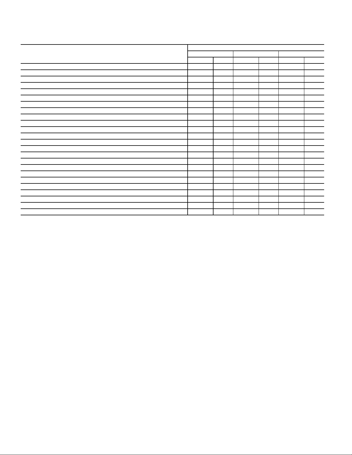
PERFORMANCE DATA
COOLING CAPACITIES (1-STAGE COOLING) 3 TONS
582J*04A
TC 28.7 28.7 32.6 25.1 25.1 28.6 22.2 22.2 25.3 19.5 19.5
58
SHC 24.8 28.7 32.6 21.7 25.1 28.6 19.1 22.2 25.3 16.7 19.5
TC 31.8 31.8 32.4 26.0 26.0 29.5 22.3 22.3 26.4 19.5 19.5
62
SHC 23.3 27.9 32.4 20.6 25.0 29.5 18.1 22.3 26.4 15.8 19.5
900
EAT
CFM
(wb)
1050
EAT
CFM
(wb)
1200
EAT
CFM
(wb)
1350
EAT
CFM
(wb)
1500
EAT
CFM
(wb)
LEGEND
——Do not operate
cfm — Cubic feet per minute (supply air)
EAT (db) — Entering air temperature (dry bulb)
EAT (wb) — Entering air temperature (wet bulb)
SHC — Sensible heat capacity (1000 Btuh) gross
TC — Total capacity (1000 Btuh) gross
TC 36.5 36.5 36.5 34.2 34.2 34.2 29.2 29.2 29.2 23.7 23.7
67
SHC 19.4 24.0 28.5 18.4 22.9 27.4 16.2 20.8 25.3 14.1 18.6
TC 40.3 40.3 40.3 38.2 38.2 38.2 35.6 35.6 35.6 32.4 32.4
72
SHC 14.9 19.5 24.1 13.9 18.5 23.1 12.9 17.4 22.0 11.6 16.2
TC — 43.1 43.1 — 41.0 41.0 — 38.6 38.6 — 35.9
76
SHC — 15.7 20.6 — 14.8 19.8 — 13.9 18.8 — 12.8
TC 31.8 31.8 36.2 28.3 28.3 32.1 24.9 24.9 28.4 21.9 21.9
58
SHC 27.5 31.8 36.2 24.4 28.3 32.1 21.5 24.9 28.4 18.8 21.9
TC 33.8 33.8 36.1 28.9 28.9 33.4 25.0 25.0 29.6 21.9 21.9
62
SHC 25.7 30.9 36.1 23.2 28.3 33.4 20.4 25.0 29.6 17.8 21.9
TC 37.8 37.8 37.8 35.5 35.5 35.5 31.7 31.7 31.7 25.8 25.8
67
SHC 20.7 25.9 31.1 19.7 24.9 30.1 18.1 23.3 28.6 15.8 21.0
TC 41.5 41.5 41.5 39.3 39.3 39.3 36.8 36.8 36.8 33.6 33.6
72
SHC 15.4 20.6 25.8 14.5 19.7 24.9 13.5 18.7 23.9 12.2 17.5
TC — 44.2 44.2 — 42.0 42.0 — 39.6 39.6 — 36.9
76
SHC — 16.4 22.1 — 15.5 21.1 — 14.5 20.0 — 13.5
TC 34.1 34.1 38.8 31.3 31.3 35.6 27.5 27.5 31.2 24.1 24.1
58
SHC 29.5 34.1 38.8 27.0 31.3 35.6 23.7 27.5 31.2 20.7 24.1
TC 34.9 34.9 39.1 32.9 32.9 35.5 27.5 27.5 32.6 24.1 24.1
62
SHC 27.5 33.3 39.1 25.2 30.3 35.5 22.5 27.5 32.6 19.6 24.1
TC 38.8 38.8 38.8 36.4 36.4 36.4 33.3 33.3 33.3 27.7 27.7
67
SHC 21.9 27.7 33.5 20.9 26.7 32.6 19.6 25.5 31.4 17.4 23.3
TC 42.4 42.4 42.4 40.1 40.1 40.1 37.7 37.7 37.7 34.5 34.5
72
SHC 15.8 21.6 27.4 14.9 20.7 26.5 13.9 19.8 25.6 12.7 18.7
TC — 44.9 44.9 — 42.7 42.7 — 40.3 40.3 — 37.7
76
SHC — 16.8 23.1 — 15.9 22.1 — 15.0 21.1 — 14.0
TC 35.6 35.6 40.4 33.6 33.6 38.1 29.8 29.8 33.9 26.2 26.2
58
SHC 30.8 35.6 40.4 29.0 33.6 38.1 25.7 29.8 33.9 22.5 26.2
TC 36.3 36.3 39.9 33.7 33.7 39.7 29.9 29.9 35.3 26.2 26.2
62
SHC 28.2 34.1 39.9 27.6 33.7 39.7 24.4 29.9 35.3 21.4 26.2
TC 39.5 39.5 39.5 37.2 37.2 37.2 34.0 34.0 34.0 29.3 29.3
67
SHC 22.9 29.4 35.8 22.0 28.5 34.9 20.8 27.3 33.9 18.9 25.4
TC 43.0 43.0 43.0 40.7 40.7 40.7 38.3 38.3 38.3 35.2 35.2
72
SHC 16.2 22.5 28.9 15.3 21.7 28.1 14.3 20.8 27.2 13.2 19.7
TC — 45.5 45.5 — 43.3 43.3 — 40.8 40.8 — 38.1
76
SHC — 17.3 24.0 — 16.4 23.1 — 15.4 22.1 — 14.5
TC 36.8 36.8 41.8 34.8 34.8 39.5 32.0 32.0 36.4 28.1 28.1
58
SHC 31.9 36.8 41.8 30.1 34.8 39.5 27.7 32.0 36.4 24.2 28.1
TC 36.9 36.9 43.5 35.4 35.4 38.8 32.1 32.1 37.9 28.1 28.1
62
SHC 30.2 36.9 43.5 27.4 33.1 38.8 26.2 32.1 37.9 22.9 28.1
TC 40.1 40.1 40.1 37.7 37.7 37.7 34.7 34.7 36.2 30.7 30.7
67
SHC 23.9 31.0 38.0 23.0 30.1 37.2 21.9 29.0 36.2 20.3 27.5
TC 43.6 43.6 43.6 41.3 41.3 41.3 38.7 38.7 38.7 35.7 35.7
72
SHC 16.5 23.4 30.2 15.6 22.5 29.5 14.7 21.7 28.6 13.6 20.8
TC — 46.0 46.0 — 43.7 43.7 — 41.2 41.2 — 38.5
76
SHC — 17.6 24.8 — 16.7 23.9 — 15.8 22.9 — 14.8
85 95 105 115
EA (db) EA (db) EA (db) EA (db)
75 80 85 75 80 85 75 80 85 75 80
AMBIENT TEMPERATURE
125
EA (db)
85 75 80 85
22.2 16.7 16.7 19.2
22.2 14.3 16.7 19.2
23.2 16.8 16.8 20.0
23.2 13.5 16.8 20.0
23.7 18.3 18.3 20.9
23.1 11.9 16.4 20.9
32.4 27.6 27.6 27.6
20.7 9.8 14.4 18.9
35.9 — 32.7 32.7
17.6 — 11.6 16.2
24.9 18.8 18.8 21.5
24.9 16.1 18.8 21.5
26.0 18.9 18.9 22.5
26.0 15.3 18.9 22.5
26.2 20.0 20.0 23.8
26.2 13.5 18.7 23.8
33.6 29.9 29.9 29.9
22.7 10.8 16.1 21.3
36.9 — 33.7 33.7
18.9 — 12.3 17.6
27.4 20.8 20.8 23.7
27.4 17.8 20.8 23.7
28.6 20.8 20.8 24.8
28.6 16.9 20.8 24.8
29.2 21.6 21.6 26.5
29.2 15.0 20.8 26.5
34.5 30.9 30.9 30.9
24.6 11.4 17.4 23.3
3.7 — 34.4 34.4
20.1 — 12.9 18.9
29.8 22.6 22.6 25.8
29.8 19.4 22.6 25.8
31.0 22.7 22.7 26.9
31.0 18.4 22.7 26.9
32.0 23.1 23.1 29.0
32.0 16.4 22.7 29.0
35.2 31.6 31.6 31.6
26.3 11.9 18.5 25.1
38.1 — 35.0 35.0
21.1 — 13.4 20.0
31.9 24.3 24.3 27.7
31.9 20.9 24.3 27.7
33.3 24.4 24.4 28.9
33.3 19.8 24.4 28.9
34.6 24.5 24.5 31.3
34.6 17.7 24.5 31.3
35.7 32.1 32.1 32.1
27.9 12.4 19.6 26.8
38.5 — 35.4 35.4
22.0 — 13.8 21.1
21
Page 22

t
ldb
= Wet-bulb temperature corresponding to enthalpy of air leaving evapora-
tor coil (h
lwb
)
Where h
ewb
= Enthalpy of air entering evaporator coil
t
ldb
=t
edb
– sensible capacity (Btuh)
1.10 x cfm
h
lwb
=h
ewb
– total capacity (Btuh)
4.5 x cfm
PERFORMANCE DATA (CONT)
COOLING CAPACITIES (1-STAGE COOLING) 3 TONS (cont)
582J*04G (3 TONS) - UNIT WITH PERFECT HUMIDITY SYSTEM IN SUBCOOLING MODE
AIR ENTERING EVAPORATOR - SCFM
TEMP (F) AIR ENT
CONDENSER (Edb)
72 67 62 72 67 62 72 67 62
TC 30.9 32.0 31.9 30.7 33.5 34.3 34.8 31.8 27.6
75
SHC 15.1 20.0 26.3 25.1 20.4 15.4 14.0 18.2 21.9
kW 2.51 2.49 2.42 2.82 2.74 2.68 3.09 3.01 2.88
TC 32.8 28.4 23.4 18.7 23.8 29.3 24.5 18.8 13.6
85
SHC 11.0 14.6 17.9 13.4 10.3 7.1 2.6 5.6 8.6
kW 3.36 3.23 3.06 3.62 3.41 3.24 3.79 3.58 3.39
TC 31.3 32.0 31.9 30.7 33.5 34.3 34.8 31.8 27.6
95
SHC 15.3 20.0 26.3 25.1 20.4 15.4 14.0 18.2 21.9
kW 2.53 2.49 2.41 2.82 2.74 2.68 3.09 3.01 2.88
TC 32.8 28.4 23.4 18.7 23.8 29.3 24.5 18.8 13.6
105
SHC 11.0 14.6 17.9 13.4 10.3 7.1 2.6 5.6 8.6
kW 3.36 3.23 3.06 3.62 3.41 3.24 3.79 3.58 3.39
TC 31.3 32.0 31.9 30.7 33.5 34.3 34.8 31.8 27.6
115
SHC 15.3 20.0 26.3 25.1 20.4 15.4 14.0 18.2 21.9
kW 2.53 2.49 2.41 2.82 2.74 2.68 3.09 3.01 2.88
LEGEND NOTES:
Edb — Entering dry-bulb
Ewb — Entering wet-bulb
kW — Compressor motor power input
Ldb — Leaving dry-bulb
Lwb — Leaving wet-bulb
SHC — Sensible capacity (1000 Btuh) gross
TC — Total capacity (1000 Btuh) gross
900 1200 1500
Air Entering Evaporator - Ewb (F)
1. Direct interpolation is permissible. Do not extrapolate.
2. The following formulas may be used:
22
Page 23

COOLING CAPACITIES (1 STAGE-COOLING) 3 TONS (cont)
t
ldb
= Wet-bulb temperature corresponding to enthalpy of air leaving evapora-
tor coil (h
lwb
)
Where h
ewb
= Enthalpy of air entering evaporator coil
t
ldb
=t
edb
– sensible capacity (Btuh)
1.10 x cfm
h
lwb
=h
ewb
– total capacity (Btuh)
4.5 x cfm
582J*04G (3 TONS) - UNIT WITH PERFECT HUMIDITY SYSTEM IN HOT GAS REHEAT MODE
AIR ENTERING EVAPORATOR - Ewb (F)
75 Dry Bulb
TEMP (F) AIR ENT
CONDENSER (Edb)
TC 12.26 13.13 13.65 13.53 14.48 15.00 14.73 15.63 16.20
80
SHC 1.76 3.87 6.09 0.75 2.48 4.33 -0.06 1.30 2.81
kW 1.92 1.93 1.94 1.96 1.98 2.00 2.00 2.01 2.02
TC 14.64 15.64 16.30 15.84 16.73 17.32 16.80 17.38 17.91
75
SHC 3.87 6.09 8.38 2.88 4.59 6.29 2.03 3.14 4.39
kW 1.87 1.88 1.88 1.89 1.90 1.91 1.91 1.92 1.93
TC 16.72 17.62 18.01 17.42 18.17 18.62 18.02 18.69 18.87
70
SHC 5.89 7.85 9.40 4.65 6.08 7.35 3.71 5.09 5.59
kW 1.78 1.80 1.82 1.81 1.83 1.84 1.82 1.82 1.86
TC 17.43 18.50 18.28 18.09 19.03 19.41 18.32 18.29 19.33
60
SHC 7.75 10.06 9.51 7.08 8.34 9.60 6.29 6.94 7.88
kW 1.66 1.62 1.70 1.67 1.69 1.68 1.69 1.70 1.71
TC 17.82 18.59 19.72 18.31 19.73 20.26 18.76 20.21 20.73
50
SHC 6.40 7.99 10.05 4.79 6.71 7.97 3.40 5.11 6.16
kW 1.98 2.03 1.94 2.01 1.94 1.97 2.03 1.96 1.99
TC 17.70 19.38 19.85 19.10 20.30 20.34 19.53 20.76 21.26
40
SHC 6.30 8.74 10.17 5.54 7.26 8.05 4.13 5.64 6.67
kW 2.07 1.95 1.99 1.93 1.91 2.02 1.96 1.94 1.97
LEGEND NOTES:
Edb — Entering dry-bulb
Ewb — Entering wet-bulb
kW — Compressor motor power input
Ldb — Leaving dry-bulb
Lwb — Leaving wet-bulb
SHC — Sensible capacity (1000 Btuh) gross
TC — Total capacity (1000 Btuh) gross
62.5 Wet Bulb
(50%Relative)
Air Entering Evaporator - cfm
900 1200 1500 900 1200 1500 900 1200 1500
75 Dry Bulb
64 Wet Bulb
(56% Relative)
1. Direct interpolation is permissible. Do not extrapolate.
2. The following formulas may be used:
75 Dry Bulb
65.3 Wet Bulb
(60% Relative)
23
Page 24

PERFORMANCE DATA (CONT)
COOLING CAPACITIES (1-STAGE COOLING) 4 TONS
582J*05A
TC 41.5 41.5 47.0 38.9 38.9 44.0 36.2 36.2 41.0 33.4 33.4 37.8 30.4 30.4 34.5
58
SHC 36.1 41.5 47.0 33.8 38.9 44.0 31.4 36.2 41.0 28.9 33.4 37.8 26.3 30.4 34.5
TC 44.9 44.9 44.9 41.4 41.4 42.6 37.8 37.8 40.8 34.0 34.0 38.8 30.5 30.5 36.0
62
SHC 32.6 38.5 44.3 30.9 36.8 42.6 29.2 35.0 40.8 27.3 33.1 38.8 25.0 30.5 36.0
1200
CFM
1400
CFM
1600
CFM
1800
CFM
2000
CFM
LEGEND
——Do not operate
cfm — Cubic feet per minute (supply air)
EAT (db) — Entering air temperature (dry bulb)
EAT (wb) — Entering air temperature (wet bulb)
SHC — Sensible heat capacity (1000 Btuh) gross
TC — Total capacity (1000 Btuh) gross
EAT
(wb)
EAT
(wb)
EAT
(wb)
EAT
(wb)
EAT
(wb)
TC 49.7 49.7 49.7 46.8 46.8 46.8 43.1 43.1 43.1 39.2 39.2 39.2 35.1 35.1 35.1
67
SHC 26.5 32.4 38.2 25.3 31.1 37.0 23.7 29.6 35.5 22.1 27.9 33.8 20.4 26.3 32.2
TC 53.4 53.4 53.4 51.3 51.3 51.3 48.5 48.5 48.5 44.7 44.7 44.7 40.7 40.7 40.7
72
SHC 19.8 25.7 31.6 19.0 24.8 30.7 17.8 23.7 29.6 16.4 22.3 28.1 14.8 20.7 26.6
TC — 55.3 55.3 — 53.3 53.3 — 51.6 51.6 — 48.6 48.6 — 44.8 44.8
76
SHC — 20.1 26.7 — 19.4 26.0 — 18.7 25.3 — 17.5 23.8 — 16.1 22.2
TC 44.4 44.4 50.2 41.6 41.6 47.0 38.7 38.7 43.8 35.7 35.7 40.5 32.6 32.6 37.0
58
SHC 38.6 44.4 50.2 36.1 41.6 47.0 33.6 38.7 43.8 31.0 35.7 40.5 28.2 32.6 37.0
TC 46.6 46.6 48.6 43.1 43.1 46.9 39.4 39.4 44.9 35.8 35.8 42.1 32.7 32.7 38.5
62
SHC 35.2 41.9 48.6 33.5 40.2 46.9 31.7 38.3 44.9 29.4 35.8 42.1 26.8 32.7 38.5
TC 51.2 51.2 51.2 48.5 48.5 48.5 44.7 44.7 44.7 40.7 40.7 40.7 36.4 36.4 36.4
67
SHC 28.0 34.6 41.2 26.9 33.6 40.3 25.4 32.2 38.9 23.8 30.6 37.3 22.1 28.9 35.7
TC 54.4 54.4 54.4 52.3 52.3 52.3 49.9 49.9 49.9 46.2 46.2 46.2 42.0 42.0 42.0
72
SHC 20.2 26.7 33.2 19.4 25.9 32.5 18.5 25.2 31.9 17.1 23.8 30.6 15.5 22.3 29.0
TC — 55.9 55.9 — 53.9 53.9 — 52.1 52.1 — 49.7 49.7 — 46.0 46.0
76
SHC — 20.8 28.5 — 20.0 27.6 — 19.2 26.5 — 18.1 25.3 — 16.8 23.8
TC 46.6 46.6 52.7 43.8 43.8 49.6 40.8 40.8 46.2 37.7 37.7 42.7 34.5 34.5 39.1
58
SHC 40.5 46.6 52.7 38.1 43.8 49.6 35.4 40.8 46.2 32.7 37.7 42.7 29.9 34.5 39.1
TC 47.9 47.9 52.3 44.6 44.6 50.7 40.9 40.9 48.1 37.8 37.8 44.4 34.5 34.5 40.7
62
SHC 37.5 44.9 52.3 35.9 43.3 50.7 33.7 40.9 48.1 31.1 37.8 44.4 28.4 34.5 40.7
TC 51.5 51.5 51.5 48.7 48.7 48.7 44.9 44.9 44.9 40.7 40.7 42.0 36.3 36.3 40.2
67
SHC 30.9 38.3 45.7 30.0 37.5 45.0 28.5 36.1 43.7 26.9 34.5 42.0 25.1 32.7 40.2
TC 55.0 55.0 55.0 52.9 52.9 52.9 50.9 50.9 50.9 47.3 47.3 47.3 43.1 43.1 43.1
72
SHC 20.4 27.5 34.6 19.6 26.8 33.9 18.9 26.3 33.8 17.6 25.2 32.7 16.1 23.7 31.3
TC — 56.3 56.3 — 54.3 54.3 — 52.3 52.3 — 50.3 50.3 — 46.8 46.8
76
SHC — 21.1 29.4 — 20.2 28.3 — 19.4 27.3 — 18.6 26.5 — 17.3 25.1
TC 48.4 48.4 54.7 45.7 45.7 51.7 42.7 42.7 48.3 — 39.4 44.6 36.1 36.1 40.9
58
SHC 42.1 48.4 54.7 39.7 45.7 51.7 37.0 42.7 48.3 34.2 39.4 44.6 31.3 36.1 40.9
TC 49.1 49.1 55.6 45.9 45.9 53.7 42.7 42.7 50.2 39.5 39.5 46.4 36.1 36.1 42.5
62
SHC 39.5 47.6 55.6 37.8 45.8 53.7 35.2 42.7 50.2 32.5 39.5 46.4 29.7 36.1 42.5
TC 53.0 53.0 53.0 50.6 50.6 50.6 47.0 47.0 47.0 42.7 42.7 43.7 38.3 38.3 41.9
67
SHC 30.2 38.2 46.1 29.5 37.7 45.8 28.5 36.8 45.2 26.9 35.3 43.7 25.2 33.6 41.9
TC 55.5 55.5 55.5 53.4 53.4 53.4 51.5 51.5 51.5 48.1 48.1 48.1 43.9 43.9 43.9
72
SHC 20.6 28.2 35.7 19.8 27.5 35.2 19.2 27.3 35.4 18.1 26.4 34.6 16.6 25.0 33.3
TC — 56.6 56.6 — 54.6 54.6 — 52.5 52.5 — 50.8 50.8 — 47.3 47.3
76
SHC — 21.2 29.9 — 20.4 28.9 — 19.6 28.0 — 18.9 27.4 — 17.7 26.2
TC 49.9 49.9 56.4 47.4 47.4 53.6 44.3 44.3 50.1 40.9 40.9 46.3 37.5 37.5 42.5
58
SHC 43.4 49.9 56.4 41.2 47.4 53.6 38.4 44.3 50.1 35.5 40.9 46.3 32.5 37.5 42.5
TC 50.1 50.1 58.3 47.5 47.5 55.7 44.3 44.3 52.1 41.0 41.0 48.2 37.5 37.5 44.2
62
SHC 41.1 49.7 58.3 39.2 47.5 55.7 36.5 44.3 52.1 33.8 41.0 48.2 30.9 37.5 44.2
TC 53.5 53.5 53.5 51.3 51.3 51.3 47.8 47.8 48.1 43.5 43.5 46.6 39.0 39.0 44.8
67
SHC 31.2 39.7 48.3 30.6 39.4 48.1 29.9 39.0 48.1 28.3 37.5 46.6 26.6 35.7 44.8
TC 55.8 55.8 55.8 53.7 53.7 53.7 51.9 51.9 51.9 48.8 48.8 48.8 44.6 44.6 44.6
72
SHC 20.7 28.7 36.7 19.9 28.1 36.2 19.4 28.0 36.7 18.5 27.4 36.4 17.1 26.2 35.2
TC — 56.9 56.9 — 54.8 54.8 — 52.7 52.7 — 51.1 51.1 — 47.7 47.7
76
SHC — 21.3 30.4 — 20.5 29.4 — 19.7 28.6 — 19.1 28.2 — 18.1 27.2
85 95 105 115 125
EA (db) EA (db) EA (db) EA (db) EA (db)
75 80 85 75 80 85 75 80 85 75 80 85 75 80 85
AMBIENT TEMPERATURE
24
Page 25

COOLING CAPACITIES (1-STAGE COOLING) 4 TONS (cont)
t
ldb
= Wet-bulb temperature corresponding to enthalpy of air leaving evapora-
tor coil (h
lwb
)
Where h
ewb
= Enthalpy of air entering evaporator coil
t
ldb
=t
edb
– sensible capacity (Btuh)
1.10 x cfm
h
lwb
=h
ewb
– total capacity (Btuh)
4.5 x cfm
582J*05G (4 TONS) - UNIT WITH PERFECT HUMIDITY SYSTEM IN SUBCOOLING MODE
AIR ENTERING EVAPORATOR - SCFM
TEMP (F) AIR ENT
CONDENSER (Edb)
72 67 62 72 67 62 72 67 62
TC 35.4 37.1 41.2 40.7 43.2 41.0 44.3 42.2 35.7
75
SHC 16.4 21.6 31.5 31.3 24.3 16.9 16.0 22.4 26.9
kW 3.06 3.07 3.06 3.44 3.43 3.41 3.84 3.82 3.72
TC 43.4 36.8 29.6 22.8 30.1 37.9 31.0 23.1 15.6
85
SHC 13.0 17.6 21.5 15.5 11.7 7.8 2.0 5.7 9.2
kW 4.28 4.20 4.05 4.77 4.57 4.42 5.17 4.99 4.81
TC 34.5 34.9 35.6 42.8 40.4 37.8 42.4 43.8 39.3
95
SHC 16.3 20.9 27.7 36.7 23.8 16.2 16.4 26.1 34.3
kW 3.25 3.25 3.24 3.63 3.63 3.61 4.04 4.02 4.00
TC 44.0 40.3 33.3 26.2 33.7 41.0 34.2 26.1 18.6
105
SHC 15.1 22.9 28.9 22.6 17.2 11.1 5.0 10.6 15.8
kW 4.49 4.47 4.32 4.99 4.87 4.69 5.50 5.28 5.09
TC 33.2 33.5 38.3 39.8 37.3 35.4 40.3 42.0 41.3
115
SHC 15.6 20.3 31.2 34.7 22.3 15.3 15.9 26.2 39.6
kW 3.53 3.51 3.46 3.89 3.89 3.88 4.31 4.30 4.26
LEGEND NOTES:
Edb — Entering dry-bulb
Ewb — Entering wet-bulb
kW — Compressor motor power input
Ldb — Leaving dry-bulb
Lwb — Leaving wet-bulb
SHC — Sensible capacity (1000 Btuh) gross
TC — Total capacity (1000 Btuh) gross
1200 1600 2000
Air Entering Evaporator - Ewb (F)
1. Direct interpolation is permissible. Do not extrapolate.
2. The following formulas may be used:
25
Page 26

t
ldb
= Wet-bulb temperature corresponding to enthalpy of air leaving evapora-
tor coil (h
lwb
)
Where h
ewb
= Enthalpy of air entering evaporator coil
t
ldb
=t
edb
– sensible capacity (Btuh)
1.10 x cfm
h
lwb
=h
ewb
– total capacity (Btuh)
4.5 x cfm
PERFORMANCE DATA (CONT)
COOLING CAPACITIES (1-STAGE COOLING) 4 TONS (cont)
582J*05G (4 TONS) - UNIT WITH PERFECT HUMIDITY SYSTEM IN HOT GAS REHEAT MODE
72 Dry Bulb
TEMP (F) AIR ENT
CONDENSER (Edb)
1200 1600 2000 1200 1600 2000 1200 1600 2000
TC 15.33 16.26 16.40 17.32 18.21 18.24 18.97 19.72 19.66
80
SHC 0.84 3.06 4.94 -0.09 1.62 2.93 -0.90 0.33 1.18
kW 2.41 2.42 2.42 2.43 2.43 2.43 2.44 2.44 2.44
TC 19.17 20.36 20.57 20.97 21.94 21.95 22.30 23.03 22.88
75
SHC 4.46 6.89 8.60 3.50 5.31 6.45 2.61 3.93 4.64
kW 2.76 2.75 2.75 2.76 2.75 2.74 2.76 2.76 2.75
TC 22.63 23.67 23.55 23.97 24.55 24.19 24.87 25.09 24.52
70
SHC 7.91 10.13 11.21 6.83 8.40 9.04 5.88 7.04 7.39
kW 2.80 2.78 2.77 2.80 2.77 2.76 2.81 2.80 2.78
TC 27.32 28.34 21.46 27.68 16.17 25.05 28.38 18.51 20.56
60
SHC 13.66 15.45 13.04 11.75 4.46 12.58 11.21 10.82 10.87
kW 2.85 2.86 2.86 2.89 2.80 2.91 2.88 2.84 2.88
TC 11.00 11.31 12.76 14.48 13.83 13.72 15.32 15.18 17.14
50
SHC 7.10 9.20 11.20 5.13 6.46 9.10 4.21 4.49 6.19
kW 2.95 2.94 2.93 2.94 2.92 2.92 2.94 2.93 2.92
TC 9.73 9.83 9.75 12.40 12.60 12.20 15.23 15.45 15.13
40
SHC 8.46 9.50 9.20 7.57 8.47 9.50 7.64 8.14 8.80
kW 3.04 3.04 3.03 3.03 3.01 3.01 3.03 3.02 3.02
LEGEND NOTES:
Edb — Entering dry-bulb
Ewb — Entering wet-bulb
kW — Compressor motor power input
Ldb — Leaving dry-bulb
Lwb — Leaving wet-bulb
SHC — Sensible capacity (1000 Btuh) gross
TC — Total capacity (1000 Btuh) gross
62.4 Wet Bulb
(50% Relative)
Air Entering Evaporator - cfm
75 Dry Bulb
64 Wet Bulb
(56% Relative)
1. Direct interpolation is permissible. Do not extrapolate.
2. The following formulas may be used:
75 Dry Bulb
65.3 Wet Bulb
(60% Relative)
26
Page 27

COOLING CAPACITIES (1-STAGE COOLING) 5 TONS
582J*06A
TC 53.0 53.0 60.2 50.0 50.0 56.8 46.9 46.9 53.4 44.4 44.4 50.4 40.9 40.9 46.5
58
SHC 45.9 53.0 60.2 43.1 50.0 56.8 40.3 46.9 53.4 38.4 44.4 50.4 35.3 40.9 46.5
TC 56.0 56.0 57.5 52.2 52.2 55.4 48.2 48.2 53.3 44.7 44.7 52.1 41.0 41.0 48.5
62
SHC 41.4 49.5 57.5 39.3 47.4 55.4 37.2 45.2 53.3 36.2 44.2 52.1 33.5 41.0 48.5
1500
CFM
1750
CFM
2000
CFM
2250
CFM
2500
CFM
LEGEND
——Do not operate
cfm — Cubic feet per minute (supply air)
EAT (db) — Entering air temperature (dry bulb)
EAT (wb) — Entering air temperature (wet bulb)
SHC — Sensible heat capacity (1000 Btuh) gross
TC — Total capacity (1000 Btuh) gross
EAT
(wb)
EAT
(wb)
EAT
(wb)
EAT
(wb)
EAT
(wb)
TC 62.4 62.4 62.4 58.8 58.8 58.8 54.8 54.8 54.8 51.0 51.0 51.0 46.1 46.1 46.1
67
SHC 33.5 41.4 49.4 31.7 39.7 47.7 29.6 37.7 45.7 28.6 36.6 44.6 26.8 34.8 42.8
TC 67.5 67.5 67.5 64.3 64.3 64.3 60.7 60.7 60.7 55.4 55.4 55.4 52.3 52.3 52.3
72
SHC 25.0 32.4 39.8 23.3 31.0 38.6 21.5 29.3 37.0 19.8 27.2 34.7 18.7 26.5 34.4
TC — 71.1 71.1 — 68.3 68.3 — 64.8 64.8 — 58.4 58.4 — 55.2 55.2
76
SHC — 25.6 32.7 — 24.2 31.3 — 22.5 29.9 — 20.3 27.7 — 19.3 26.7
TC 56.7 56.7 64.3 53.5 53.5 60.8 50.2 50.2 57.2 47.4 47.4 53.9 43.8 43.8 49.7
58
SHC 49.1 56.7 64.3 46.2 53.5 60.8 43.3 50.2 57.2 41.0 47.4 53.9 37.8 43.8 49.7
TC 58.3 58.3 63.9 54.4 54.4 61.8 51.8 51.8 56.4 47.5 47.5 56.1 43.8 43.8 51.8
62
SHC 45.3 54.6 63.9 43.2 52.5 61.8 39.6 48.0 56.4 38.9 47.5 56.1 35.9 43.8 51.8
TC 64.0 64.0 64.0 60.6 60.6 60.6 56.6 56.6 56.6 52.3 52.3 52.3 47.7 47.7 47.7
67
SHC 35.5 44.5 53.6 33.9 43.1 52.4 32.0 41.3 50.6 30.6 39.7 48.8 29.1 38.4 47.7
TC 68.9 68.9 68.9 65.9 65.9 65.9 62.2 62.2 62.2 56.6 56.6 56.6 53.2 53.2 53.2
72
SHC 25.5 33.9 42.2 24.0 32.7 41.4 22.2 31.1 40.1 20.2 28.7 37.1 19.2 28.1 37.1
TC — 72.4 72.4 — 69.7 69.7 — 66.1 66.1 — 59.5 59.5 — 56.1 56.1
76
SHC — 26.4 34.9 — 24.9 33.2 — 23.2 31.7 — 21.0 29.5 — 19.8 28.3
TC 59.8 59.8 67.8 56.5 56.5 64.2 53.1 53.1 60.4 50.0 50.0 56.8 46.2 46.2 52.4
58
SHC 51.8 59.8 67.8 48.9 56.5 64.2 45.8 53.1 60.4 43.3 50.0 56.8 39.9 46.2 52.4
TC 60.2 60.2 69.7 57.0 57.0 66.0 53.2 53.2 62.9 50.1 50.1 59.2 46.2 46.2 54.6
62
SHC 48.8 59.3 69.7 46.1 56.0 66.0 43.4 53.2 62.9 41.1 50.1 59.2 37.8 46.2 54.6
TC 65.3 65.3 65.3 61.8 61.8 61.8 56.7 56.7 57.6 52.4 52.4 55.7 47.6 47.6 54.5
67
SHC 37.3 47.4 57.4 35.9 46.2 56.6 36.4 47.0 57.6 34.9 45.3 55.7 33.5 44.0 54.5
TC 70.2 70.2 70.2 67.0 67.0 67.0 63.2 63.2 63.2 57.3 57.3 57.3 54.0 54.0 54.0
72
SHC 26.1 35.4 44.8 24.5 34.1 43.7 22.8 32.7 42.6 20.6 30.1 39.5 19.6 29.5 39.3
TC — 73.4 73.4 — 70.6 70.6 — 67.1 67.1 — 60.3 60.3 — 56.7 56.7
76
SHC — 27.0 36.5 — 25.5 35.0 — 23.8 33.3 — 21.5 31.0 — 20.3 29.9
TC 62.2 62.2 70.5 59.0 59.0 66.9 55.5 55.5 63.0 52.1 52.1 59.1 48.2 48.2 54.7
58
SHC 54.0 62.2 70.5 51.1 59.0 66.9 47.9 55.5 63.0 45.0 52.1 59.1 41.7 48.2 54.7
TC 63.4 63.4 70.9 59.1 59.1 69.7 55.5 55.5 65.6 52.1 52.1 61.5 48.3 48.3 57.0
62
SHC 50.2 60.5 70.9 48.5 59.1 69.7 45.4 55.5 65.6 42.7 52.1 61.5 39.5 48.3 57.0
TC 66.3 66.3 66.3 62.4 62.4 62.4 58.9 58.9 59.6 54.1 54.1 56.3 49.9 49.9 56.8
67
SHC 38.9 50.0 61.0 39.2 50.8 62.3 36.2 47.9 59.6 34.0 45.2 56.3 33.4 45.1 56.8
TC 71.1 71.1 71.1 68.0 68.0 68.0 64.1 64.1 64.1 57.9 57.9 57.9 54.4 54.4 54.4
72
SHC 26.5 36.8 47.1 25.0 35.5 46.1 23.3 34.1 45.0 21.0 31.3 41.7 19.9 30.6 41.2
TC — 74.0 74.0 — 71.4 71.4 — 67.8 67.8 — 61.0 61.0 — 57.2 57.2
76
SHC — 27.3 37.6 — 26.0 36.5 — 24.3 34.9 — 21.8 32.2 — 20.7 31.2
TC 64.0 64.0 72.4 60.9 60.9 69.1 57.4 57.4 65.2 53.3 53.3 60.5 50.0 50.0 56.7
58
SHC 55.5 64.0 72.4 52.8 60.9 69.1 49.6 57.4 65.2 46.1 53.3 60.5 43.2 50.0 56.7
TC 64.0 64.0 75.3 61.0 61.0 71.9 57.4 57.4 67.9 53.4 53.4 63.0 50.0 50.0 59.0
62
SHC 52.7 64.0 75.3 50.1 61.0 71.9 47.0 57.4 67.9 43.8 53.4 63.0 41.0 50.0 59.0
TC 67.3 67.3 67.3 63.7 63.7 64.5 59.5 59.5 64.2 54.6 54.6 59.3 50.7 50.7 60.9
67
SHC 40.6 52.5 64.5 39.6 52.0 64.5 38.7 51.5 64.2 35.4 47.3 59.3 35.4 48.2 60.9
TC 71.7 71.7 71.7 68.8 68.8 68.8 64.9 64.9 64.9 58.4 58.4 58.4 54.9 54.9 54.9
72
SHC 26.7 37.9 49.1 25.4 37.0 48.5 23.7 35.5 47.3 21.2 32.4 43.6 20.3 31.9 43.5
TC — 74.5 74.5 — 72.1 72.1 — 68.4 68.4 — 61.6 61.6 — 57.7 57.7
76
SHC — 27.4 38.5 — 26.3 37.7 — 24.7 36.3 — 22.1 33.3 — 20.9 32.3
85 95 105 115 125
EA (db) EA (db) EA (db) EA (db) EA (db)
75 80 85 75 80 85 75 80 85 75 80 85 75 80 85
AMBIENT TEMPERATURE
27
Page 28

t
ldb
= Wet-bulb temperature corresponding to enthalpy of air leaving evapora-
tor coil (h
lwb
)
Where h
ewb
= Enthalpy of air entering evaporator coil
t
ldb
=t
edb
– sensible capacity (Btuh)
1.10 x cfm
h
lwb
=h
ewb
– total capacity (Btuh)
4.5 x cfm
PERFORMANCE DATA (CONT)
COOLING CAPACITIES (1-STAGE COOLING) 5 TONS (cont)
582J*06G (5 TONS) - UNIT WITH PERFECT HUMIDITY SYSTEM IN SUBCOOLING MODE
AIR ENTERING EVAPORATOR - SCFM
TEMP (F) AIR ENT
CONDENSER (Edb)
72 67 62 72 67 62 72 67 62
TC 51.1 56.4 57.9 47.8 49.9 57.3 49.6 48.9 53.8
75
SHC 25.5 36.1 50.4 24.6 31.3 50.3 25.8 32.0 44.8
kW 3.20 3.30 3.19 3.25 3.18 3.13 3.22 3.13 3.25
TC 54.1 60.4 61.0 56.4 60.4 60.5 56.7 60.7 58.2
85
SHC 47.2 38.7 28.0 52.3 40.6 28.8 27.2 42.6 56.5
kW 3.59 3.67 3.79 3.81 3.70 3.60 3.70 3.74 3.61
TC 62.4 56.6 48.4 62.7 58.6 50.5 62.8 60.0 52.6
95
SHC 26.3 34.9 41.9 27.8 38.7 46.9 29.0 42.1 51.5
kW 4.20 4.09 3.92 3.97 4.10 4.25 4.28 4.12 4.03
TC 58.8 49.9 41.6 60.5 51.9 43.6 61.6 53.5 47.6
105
SHC 22.0 29.0 35.8 24.4 32.9 40.7 26.5 36.6 42.3
kW 4.64 4.46 4.28 4.33 4.52 4.66 4.69 4.57 4.41
TC 51.4 41.9 33.8 53.3 43.7 35.9 54.7 45.3 39.2
115
SHC 15.7 22.2 29.0 18.1 26.0 33.9 20.4 29.7 35.3
kW 5.08 4.83 4.63 4.69 4.88 5.14 5.19 4.92 4.77
LEGEND NOTES:
Edb — Entering dry-bulb
Ewb — Entering wet-bulb
kW — Compressor motor power input
Ldb — Leaving dry-bulb
Lwb — Leaving wet-bulb
SHC — Sensible capacity (1000 Btuh) gross
TC — Total capacity (1000 Btuh) gross
1750 2000 2250
Air Entering Evaporator - Ewb (F)
1. Direct interpolation is permissible. Do not extrapolate.
2. The following formulas may be used:
28
Page 29

COOLING CAPACITIES (1-STAGE COOLING) 5 TONS (cont)
t
ldb
= Wet-bulb temperature corresponding to enthalpy of air leaving evapora-
tor coil (h
lwb
)
Where h
ewb
= Enthalpy of air entering evaporator coil
t
ldb
=t
edb
– sensible capacity (Btuh)
1.10 x cfm
h
lwb
=h
ewb
– total capacity (Btuh)
4.5 x cfm
582J*06G (5 TONS) - UNIT WITH PERFECT HUMIDITY SYSTEM IN HOT GAS REHEAT MODE
AIR ENTERING EVAPORATOR - Ewb (F)
75 Dry Bulb
TEMP (F) AIR ENT
CONDENSER (Edb)
1750 2000 2250 1750 2000 2250 1750 2000 2250
TC 13.19 12.95 12.70 14.56 14.30 14.00 15.70 15.44 15.05
80
SHC -2.38 -1.55 -0.65 -4.75 -4.25 -3.69 -6.74 -6.49 -6.21
kW 3.15 3.16 3.16 3.19 3.20 3.20 3.22 3.23 3.23
TC 16.14 15.95 15.71 17.36 17.20 16.84 18.30 18.20 17.81
75
SHC 0.44 1.23 2.03 -1.92 -1.36 -0.96 -3.90 -3.50 -3.31
kW 3.04 3.05 3.06 3.07 3.08 3.09 3.10 3.12 3.12
TC 18.90 18.68 18.52 19.97 19.85 19.50 20.86 20.62 20.17
70
SHC 3.13 3.80 4.51 0.85 1.39 1.70 -0.97 -0.69 -0.63
kW 2.92 2.93 2.95 2.96 2.97 2.98 2.98 2.99 3.00
TC 23.71 23.48 23.16 24.05 23.98 23.52 24.79 24.47 26.99
60
SHC 8.11 8.63 8.88 5.97 6.46 6.58 4.65 4.87 5.94
kW 3.17 3.23 3.15 3.21 3.26 3.18 3.23 3.12 3.10
TC 21.91 16.69 16.62 16.81 16.98 16.92 17.08 17.24 17.17
50
SHC 11.51 10.04 9.64 9.77 9.43 8.95 9.30 8.88 8.35
kW 3.01 3.07 3.11 3.04 3.10 3.15 3.07 3.14 3.18
TC 21.91 16.69 16.62 16.81 16.98 16.92 17.08 17.24 17.17
40
SHC 11.51 10.04 9.64 9.77 9.43 8.95 9.30 8.88 8.35
kW 3.39 3.32 3.24 3.14 3.23 3.15 3.18 3.27 3.08
LEGEND NOTES:
Edb — Entering dry-bulb
Ewb — Entering wet-bulb
kW — Compressor motor power input
Ldb — Leaving dry-bulb
Lwb — Leaving wet-bulb
SHC — Sensible capacity (1000 Btuh) gross
TC — Total capacity (1000 Btuh) gross
62.5 Wet Bulb
(50% Relative)
Air Entering Evaporator - cfm
75 Dry Bulb
64 Wet Bulb
(56% Relative)
1. Direct interpolation is permissible. Do not extrapolate.
2. The following formulas may be used:
75 Dry Bulb
65.3 Wet Bulb
(60% Relative)
29
Page 30

PERFORMANCE DATA (CONT)
STATIC PRESSURE ADDERS (IN. WG) (FACTORY OPTIONS AND/OR ACCESSORIES)
3 TO 5 TONS
CFM 600 800 1000 1250 1500 1750 2000 2250 2500
VERTICAL ECONOMIZER 0.012 0.020 0.030 0.046 0.066 0.089 0.115 0.145 0.179
HORIZONTAL ECONOMIZER 0.018 0.026 0.037 0.053 0.073 0.096 0.124 0.154 0.189
NOTE: All above data for both standard and ultra low leak models, where availble.
STATIC PRESSURE ADDERS (IN. WG) (FACTORY OPTIONS AND/OR ACCESSORIES)
3 TO 5 TONS
CFM 600 800 1000 1250 1500 1750 2000 2250 2500
PERFECT HUMIDITY™ 0.023 0.033 0.042 0.054 0.067 0.080 0.093 0.106 0.120
STATIC PRESSURE POWER EXHAUST PERFORMANCE (IN. WG) (FACTORY OPTIONS AND/OR ACCESSORIES)
3 TO 5 TONS
RETURN DUCT STATIC PRESSURE (IN. WG) 0.0 0.1 0.2 0.3 0.4 0.5
VERTICAL POWER EXHAUST CFM 3239 2974 2642 2244 1780 1249
STATIC PRESSURE DEDUCTIONS (IN. WG) (GAS HEAT OPTIONS)
3 TO 5 TONS
CFM 600 800 1000 1250 1500 1750 2000 2250 2500
MEDIUM
GAS HEAT
DEDUCTION
LOW GAS
HEAT
DEDUCTION
0.005 0.009 0.014 0.023 0.034 0.046 0.061 0.077 0.096
0.012 0.023 0.037 0.060 0.088 0.122 0.161 0.206 0.256
General Fan Performance Notes
1. Interpolation is permissible. Do not extrapolate.
2. External static pressure is the static pressure difference between the return duct and the supply duct plus the static pressure
caused by any FIOPs or accessories.
3. Tabular data accounts for pressure loss due to clean filters, unit casing, and wet coils. Factory options and accessories may add
static pressure losses. Selection software is available, through your salesperson, to help you select the best motor/drive combination for your application.
4. The Fan Performance tables offer motor/drive recommendations. In cases when two motor/drive combinations would work,
Bryant recommends the lower horsepower option.
5. For information on the electrical properties of Bryant motors, please see the Electrical information section of this book.
6. For more information on the performance limits of Bryant motors, see the application data section of this book.
7. The EPACT (Energy Policy Act of 1992) regulates energy requirements for specific types of indoor fan motors. Motors regulated by EPACT include any general purpose, T-frame (three-digit, 143 and larger), single-speed, foot mounted, polyphase,
squirrel cage induction motors of NEMA (National Electrical Manufacturers Association) design A and B, manufactured for
use in the United States. Ranging from 1 to 200 Hp, these continuous-duty motors operate on 230 and 460 volt, 60 Hz power. If
a motor does not fit into these specifications, the motor does not have to be replaced by an EPACT compliant energy efficient
motor. Variable speed motors are exempt from EPACT compliance requirements. Therefore, the indoor fan motors for Bryant
582J*04-06 units are exempt from these requirements.
30
Page 31

582J*04 VERTICAL UNIT - DIRECT DRIVE
SPEED
(TORQUE) TAP
1
2
3
4
5
CFM ESP BHP
900 0.28 0.18
975 0.16 0.17
1050 0.05 0.15
1125 — —
1200 — —
1275 — —
1350 — —
1425 — —
1500 — —
900 0.34 0.20
975 0.21 0.19
1050 0.09 0.17
1125 — —
1200 — —
1275 — —
1350 — —
1425 — —
1500 — —
900 0.48 0.25
975 0.34 0.23
1050 0.20 0.22
1125 0.07 0.20
1200 — —
1275 — —
1350 — —
1425 — —
1500 — —
900 1.06 0.46
975 0.98 0.48
1050 0.90 0.50
1125 0.82 0.52
1200 0.72 0.54
1275 0.61 0.53
1350 0.49 0.53
1425 0.37 0.53
1500 0.24 0.53
900 1.10 0.47
975 1.02 0.49
1050 0.93 0.51
1125 0.85 0.54
1200 0.81 0.56
1275 0.74 0.58
1350 0.67 0.61
1425 0.60 0.63
1500 0.52 0.66
582J*04 HORIZONTAL UNIT - DIRECT DRIVE
SPEED
(TORQUE) TAP
1
2
3
4
5
CFM ESP BHP
900 0.44 0.22
975 0.32 0.21
1050 0.21 0.20
1125 0.11 0.18
1200 0.04 0.16
1275 — —
1350 — —
1425 — —
1500 — —
900 0.50 0.25
975 0.38 0.23
1050 0.26 0.22
1125 0.16 0.20
1200 0.07 0.19
1275 0.00 0.16
1350 — —
1425 — —
1500 — —
900 0.66 0.30
975 0.52 0.28
1050 0.39 0.27
1125 0.27 0.26
1200 0.16 0.24
1275 0.05 0.24
1350 — —
1425 — —
1500 — —
900 1.17 0.48
975 1.10 0.49
1050 1.04 0.51
1125 0.97 0.53
1200 0.89 0.55
1275 0.81 0.56
1350 0.72 0.57
1425 0.62 0.58
1500 0.52 0.58
900 1.20 0.49
975 1.14 0.51
1050 1.04 0.53
1125 0.97 0.55
1200 0.95 0.57
1275 0.90 0.60
1350 0.84 0.62
1425 0.78 0.65
1500 0.72 0.68
31
Page 32

PERFORMANCE DATA (CONT)
582J*05 VERTICAL UNIT - DIRECT DRIVE
SPEED
(TORQUE) TAP
1
2
3
4
5
CFM ESP BHP
1200 0.35 0.36
1300 0.17 0.34
1400 0.01 0.32
1500 — —
1600 — —
1700 — —
1800 — —
1900 — —
2000 — —
1200 0.47 0.42
1300 0.28 0.39
1400 0.10 0.36
1500 — —
1600 — —
1700 — —
1800 — —
1900 — —
2000 — —
1200 0.77 0.55
1300 0.66 0.58
1400 0.54 0.60
1500 0.40 0.61
1600 0.25 0.60
1700 0.07 0.60
1800 — —
1900 — —
2000 — —
1200 0.78 0.55
1300 0.68 0.58
1400 0.58 0.61
1500 0.46 0.64
1600 0.35 0.66
1700 0.22 0.68
1800 0.09 0.70
1900 — —
2000 — —
1200 0.81 0.56
1300 0.72 0.59
1400 0.66 0.62
1500 0.55 0.66
1600 0.41 0.69
1700 0.29 0.73
1800 0.17 0.76
1900 0.05 0.80
2000 -0.06 0.83
582J*05 HORIZONTAL UNIT - DIRECT DRIVE
SPEED
(TORQUE) TAP
1
2
3
4
5
CFM ESP BHP
1200 0.57 0.41
1300 0.40 0.39
1400 0.24 0.37
1500 0.08 0.35
1600 — —
1700 — —
1800 — —
1900 — —
2000 — —
1200 0.69 0.46
1300 0.52 0.45
1400 0.36 0.43
1500 0.18 0.40
1600 0.00 0.39
1700 — —
1800 — —
1900 — —
2000 — —
1200 0.91 0.56
1300 0.83 0.59
1400 0.74 0.62
1500 0.64 0.64
1600 0.52 0.66
1700 0.39 0.66
1800 0.22 0.63
1900 0.03 0.62
2000 — —
1200 0.92 0.56
1300 0.83 0.60
1400 0.75 0.63
1500 0.67 0.66
1600 0.58 0.69
1700 0.49 0.72
1800 0.39 0.74
1900 0.26 0.76
2000 0.12 0.76
1200 0.95 0.57
1300 0.88 0.61
1400 0.80 0.64
1500 0.72 0.68
1600 0.64 0.71
1700 0.55 0.75
1800 0.46 0.79
1900 0.37 0.83
2000 0.27 0.87
32
Page 33

582J*06 VERTICAL UNIT - DIRECT DRIVE
SPEED
(TORQUE) TAP
1
2
3
4
5
CFM ESP BHP
1500 0.24 0.43
1625 0.05 0.41
1750 — —
1875 — —
2000 — —
2125 — —
2250 — —
2375 — —
2500 — —
1500 0.44 0.54
1625 0.21 0.52
1750 0.05 0.50
1875 — —
2000 — —
2125 — —
2250 — —
2375 — —
2500 — —
1500 0.89 0.81
1625 0.69 0.80
1750 0.48 0.78
1875 0.26 0.75
2000 0.06 0.73
2125 — —
2250 — —
2375 — —
2500 — —
1500 0.97 0.85
1625 0.81 0.88
1750 0.65 0.91
1875 0.47 0.87
2000 0.29 0.89
2125 0.09 0.86
2250 — —
2375 — —
2500 — —
1500 1.00 0.87
1625 0.86 0.91
1750 0.77 0.95
1875 0.65 0.98
2000 0.41 1.01
2125 0.25 0.88
2250 0.06 1.01
2375 — —
2500 — —
582J*06 HORIZONTAL UNIT - DIRECT DRIVE
SPEED
(TORQUE) TAP
1
2
3
4
5
CFM ESP BHP
1500 0.36 0.48
1625 0.17 0.45
1750 0.01 0.43
1875 — —
2000 — —
2125 — —
2250 — —
2375 — —
2500 — —
1500 0.57 0.60
1625 0.35 0.57
1750 0.15 0.54
1875 0.02 0.51
2000 — —
2125 — —
2250 — —
2375 — —
2500 — —
1500 1.02 0.86
1625 0.85 0.87
1750 0.65 0.85
1875 0.44 0.82
2000 0.23 0.80
2125 0.02 0.80
2250 — —
2375 — —
2500 — —
1500 1.09 0.90
1625 0.95 0.93
1750 0.80 0.97
1875 0.62 0.92
2000 0.43 0.97
2125 0.23 0.93
2250 0.00 0.91
2375 — —
2500 — —
1500 1.12 0.92
1625 1.00 0.96
1750 0.86 1.00
1875 0.72 1.04
2000 0.56 1.08
2125 0.39 0.95
2250 0.19 1.09
2375 — —
2500 — —
33
Page 34

PERFORMANCE DATA (CONT)
582J*04 (1 PHASE) 3 TON VERTICAL SUPPLY - BELT DRIVE
AVAILABLE EXTERNAL
CF
M
900 592 0.14 721 0.25
975 616 0.17 744 0.28
1050 641 0.19 766 0.30
1125 667 0.22
1200 693 0.25
1275 720 0.29
1350 747 0.33
1425
1500
0.
2
RPM BHP RPM BHP RPM BHP RPM BHP RPM BHP
775 0.37 887 0.50 982 0.65 1066 0.81 1141 0.99
802 0.42 912 0.55 1006 0.70 1088 0.87 1163 1.05
0.
4
790 0.33 890 0.47 978 0.63 1056 0.80
813 0.37 913 0.51 999 0.67 1077 0.84
837 0.41 935 0.55 1021 0.71 1098 0.88
862 0.45 958 0.60 1043 0.76 1119 0.94
STATIC
826 0.38 916 0.53 997 0.69
847 0.41 936 0.56 1016 0.72
868 0.44 957 0.59 1036 0.76
0.
6
PRESSURE
(in. wg)
0.
8
1.
0
AVAILABLE EXTERNAL
CF
M
900
975
1050
1125
1200
1275
1350
1425
1500
NOTE: For more information, see General Fan Performance Notes.
Boldface indicates field-supplied drive is required.
1.
2
RPM BHP RPM BHP RPM BHP RPM BHP RPM BHP
1070 0.88 1137 1.07 1201 1.29 ————
1089 0.91 1156 1.11 1219 1.32 ————
1108 0.94 1175 1.14 1238 1.36 ————
1128 0.98 1195 1.18 1257 1.40 ————
1148 1.03 1214 1.23 1276 1.44 ————
1169 1.07 1235 1.28 1296 1.50 ————
1190 1.13 1255 1.33 ——————
1211 1.19 1276 1.39 ——————
1232 1.25 1297 1.46 ——————
1.
4
582J*04 (1 PHASE) 3 TON HORIZONTAL SUPPLY - BELT DRIVE
AVAILABLE EXTERNAL
CF
M
900 582 0.14 715 0.24
975 606 0.16 735 0.26
1050 630 0.18 756 0.29
1125 655 0.21
1200 681 0.24
1275 708 0.27
1350 735 0.31
1425 762 0.35
1500
0.
2
RPM BHP RPM BHP RPM BHP RPM BHP RPM BHP
790 0.40 896 0.53 990 0.67 1074 0.83 1151 1.00
0.
4
778 0.32 882 0.45 974 0.58 1057 0.74
800 0.35 902 0.48 992 0.63 1074 0.78
823 0.39 923 0.53 1012 0.67 1093 0.83
847 0.43 945 0.57 1032 0.72 1112 0.88
871 0.48 967 0.62 1053 0.77 1131 0.94
STATIC
STATIC
825 0.35 921 0.48 1007 0.63
843 0.38 938 0.51 1023 0.66
862 0.41 955 0.55 1040 0.70
PRESSURE
1.
6
Medium static 770-1175 RPM, 1.2 BHP max
High static 1035-1466 RPM, 1.5 BHP max
PRESSURE
0.
6
(in. wg)
(in. wg)
1.
8
0.
8
2.
0
1.
0
AVAILABLE EXTERNAL
CF
M
900
975
1050
1125
1200
1275
1350
1425
1500
NOTE: For more information, see General Fan Performance Notes.
Boldface indicates field-supplied drive is required.
Medium static 770-1175 RPM, 1.2 BHP max
High static 1035-1466 RPM, 1.5 BHP max
1.
2
RPM BHP RPM BHP RPM BHP RPM BHP RPM BHP
1086 0.79 1159 0.96 1228 1.14 1293 1.33 ——
1101 0.82 1174 0.99 1242 1.18 1306 1.37 ——
1117 0.86 1189 1.03 1256 1.22 1320 1.41 ——
1133 0.90 1204 1.08 1271 1.26 1335 1.46 ——
1150 0.95 1221 1.13 1287 1.31 ————
1168 1.00 1237 1.18 1303 1.37 ————
1186 1.05 1255 1.24 1320 1.43 ————
1204 1.11 1272 1.30 1337 1.49 ————
1223 1.18 1291 1.36 ——————
1.
4
34
STATIC
1.
6
PRESSURE
(in. wg)
1.
8
2.
0
Page 35

582J*04 (3 PHASE) 3 TON VERTICAL SUPPLY - BELT DRIVE
AVAILABLE EXTERNAL
CF
M
900 592 0.14 721 0.25
975 616 0.17 744 0.28
1050 641 0.19 766 0.30
1125 667 0.22
1200 693 0.25
1275 720 0.29
1350 747 0.33
1425 775 0.37
1500
0.
2
RPM BHP RPM BHP RPM BHP RPM BHP RPM BHP
802 0.42 912 0.55 1006 0.70 1088 0.87 1163 1.05
0.
4
790 0.33 890 0.47 978 0.63 1056 0.80
813 0.37 913 0.51 999 0.67 1077 0.84
837 0.41 935 0.55 1021 0.71 1098 0.88
862 0.45 958 0.60 1043 0.76 1119 0.94
887 0.50 982 0.65 1066 0.81 1141 0.99
STATIC
826 0.38 916 0.53 997 0.69
847 0.41 936 0.56 1016 0.72
868 0.44 957 0.59 1036 0.76
0.
6
PRESSURE
(in. wg)
0.
8
1.
0
AVAILABLE EXTERNAL
CF
M
900
975
1050
1125
1200
1275
1350
1425
1500
NOTE: For more information, see General Fan Performance Notes.
Boldface indicates field-supplied drive is required.
1.
2
RPM BHP RPM BHP RPM BHP RPM BHP RPM BHP
1070 0.88 1137 1.07 1201 1.29 1260 1.51 1317 1.75
1089 0.91 1156 1.11 1219 1.32 1279 1.54 1335 1.78
1108 0.94 1175 1.14 1238 1.36 1297 1.58 1353 1.82
1128 0.98 1195 1.18 1257 1.40 1316 1.62 1372 1.86
1148 1.03 1214 1.23 1276 1.44 1335 1.67 1391 1.91
1169 1.07 1235 1.28 1296 1.50 1354 1.72 1410 1.97
1190 1.13 1255 1.33 1316 1.55 1374 1.78 1429 2.03
1211 1.19 1276 1.39 1337 1.61 1394 1.85 1449 2.09
1232 1.25 1297 1.46 1357 1.68 1415 1.91 1469 2.16
1.
4
582J*04 (3 PHASE) 3 TON HORIZONTAL SUPPLY - BELT DRIVE
AVAILABLE EXTERNAL
CF
M
900 582 0.14 715 0.24
975 606 0.16 735 0.26
1050 630 0.18 756 0.29
1125 655 0.21
1200 681 0.24
1275 708 0.27
1350 735 0.31
1425 762 0.35
1500
0.
2
RPM BHP RPM BHP RPM BHP RPM BHP RPM BHP
790 0.40 896 0.53 990 0.67 1074 0.83 1151 1.00
0.
4
778 0.32 882 0.45 974 0.58 1057 0.74
800 0.35 902 0.48 992 0.63 1074 0.78
823 0.39 923 0.53 1012 0.67 1093 0.83
847 0.43 945 0.57 1032 0.72 1112 0.88
871 0.48 967 0.62 1053 0.77 1131 0.94
STATIC
STATIC
825 0.35 921 0.48 1007 0.63
843 0.38 938 0.51 1023 0.66
862 0.41 955 0.55 1040 0.70
PRESSURE
1.
6
Medium static 770-1175 RPM, 1.7 BHP max
High static 1035-1466 RPM, 2.9 BHP max
PRESSURE
0.
6
(in. wg)
(in. wg)
1.
8
0.
8
2.
0
1.
0
AVAILABLE EXTERNAL
CF
M
900
975
1050
1125
1200
1275
1350
1425
1500
NOTE: For more information, see General Fan Performance Notes.
Boldface indicates field-supplied drive is required.
Medium static 770-1175 RPM, 1.7 BHP max
High static 1035-1466 RPM, 2.9 BHP max
1.
2
RPM BHP RPM BHP RPM BHP RPM BHP RPM BHP
1086 0.79 1159 0.96 1228 1.14 1293 1.33 1354 1.53
1101 0.82 1174 0.99 1242 1.18 1306 1.37 1367 1.57
1117 0.86 1189 1.03 1256 1.22 1320 1.41 1381 1.62
1133 0.90 1204 1.08 1271 1.26 1335 1.46 1395 1.67
1150 0.95 1221 1.13 1287 1.31 1350 1.51 1410 1.72
1168 1.00 1237 1.18 1303 1.37 1365 1.57 1425 1.78
1186 1.05 1255 1.24 1320 1.43 1382 1.63 1441 1.84
1204 1.11 1272 1.30 1337 1.49 1398 1.70 1457 1.91
1223 1.18 1291 1.36 1355 1.56 1415 1.77 1473 1.99
1.
4
STATIC
1.
6
PRESSURE
(in. wg)
1.
8
2.
0
35
Page 36

PERFORMANCE DATA (CONT)
582J*05 (1 PHASE) 4 TON VERTICAL SUPPLY - BELT DRIVE
AVAILABLE EXTERNAL
CF
M
1200 693 0.25
1300 729 0.30
1400 765 0.35
1500
1600
1700
1800
1900
2000
0.
2
RPM BHP RPM BHP RPM BHP RPM BHP RPM BHP
802 0.42 912 0.55 1006 0.70 1088 0.87 1163 1.05
840 0.49 947 0.63 1038 0.78 1119 0.95 1193 1.14
878 0.57 982 0.71 1071 0.87 1151 1.05 1224 1.24
917 0.65 1017 0.81 1105 0.97 1183 1.15 1255 1.35
956 0.75 1053 0.91 1139 1.08 1216 1.27 1287 1.47
995 0.86 1090 1.02 1173 1.20 1249 1.39 ——
0.
4
813 0.37 913 0.51 999 0.67 1077 0.84
846 0.42 943 0.57 1028 0.73 1105 0.90
879 0.48 974 0.63 1058 0.79 1134 0.97
STATIC
0.
6
PRESSURE
(in. wg)
0.
8
1.
0
AVAILABLE EXTERNAL
CF
M
1200
1300
1400
1500
1600
1700
1800 ——————————
1900 ——————————
2000 ——————————
NOTE: For more information, see General Fan Performance Notes.
Boldface indicates field-supplied drive is required.
1.
2
RPM BHP RPM BHP RPM BHP RPM BHP RPM BHP
1148 1.03 1214 1.23 1276 1.44 ————
1176 1.09 1241 1.30 ——————
1204 1.17 1269 1.37 ——————
1232 1.25 1297 1.46 ——————
1262 1.34 ————————
1291 1.44 ————————
1.
4
STATIC
PRESSURE
1.
6
Medium static 770-1175 RPM, 1.2 BHP max
High static 1035-1466 RPM, 1.5 BHP max
(in. wg)
1.
8
2.
0
582J*05 (1 PHASE) 4 TON HORIZONTAL SUPPLY - BELT DRIVE
CF
M
1200 681 0.24
1300 717 0.29
1400 753 0.34
1500
1600
1700
1800
1900
2000
0.
2
RPM BHP RPM BHP RPM BHP RPM BHP RPM BHP
790 0.40 896 0.53 990 0.67 1074 0.83 1151 1.00
828 0.46 930 0.60 1021 0.75 1103 0.91 1179 1.09
866 0.54 964 0.68 1053 0.84 1133 1.01 1207 1.18
905 0.62 1000 0.77 1085 0.94 1164 1.11 1236 1.29
944 0.71 1036 0.87 1119 1.04 1195 1.22 1266 1.41
984 0.82 1072 0.98 1153 1.15 1227 1.34 ——
AVAILABLE EXTERNAL
0.
4
800 0.35 902 0.48 992 0.63 1074 0.78
831 0.41 930 0.54 1019 0.69 1099 0.85
863 0.46 959 0.60 1046 0.75 1125 0.92
STATIC
0.
6
PRESSURE
(in. wg)
0.
8
1.
0
AVAILABLE EXTERNAL
CF
M
1200
1300
1400
1500
1600
1700
1800
1900 ——————————
2000 ——————————
NOTE: For more information, see General Fan Performance Notes.
Boldface indicates field-supplied drive is required.
Medium static 770-1175 RPM, 1.2 BHP max
High static 1035-1466 RPM, 1.5 BHP max
1.
2
RPM BHP RPM BHP RPM BHP RPM BHP RPM BHP
1150 0.95 1221 1.13 1287 1.31 ————
1173 1.02 1243 1.20 1309 1.39 ————
1198 1.09 1266 1.28 1331 1.47 ————
1223 1.18 1291 1.36 ——————
1249 1.27 1316 1.46 ——————
1277 1.37 ————————
1305 1.48 ————————
1.
4
STATIC
1.
6
PRESSURE
(in. wg)
1.
8
2.
0
36
Page 37

582J*05 (3 PHASE) 4 TON VERTICAL SUPPLY - BELT DRIVE
AVAILABLE EXTERNAL
CF
M
1200 693 0.25 813 0.37 913 0.51
1300 729 0.30 846 0.42
1400 765 0.35 879 0.48
1500 802 0.42 912 0.55
1600 840 0.49
1700 878 0.57
1800 917 0.65
1900
2000
0.
2
RPM BHP RPM BHP RPM BHP RPM BHP RPM BHP
956 0.75 1053 0.91 1139 1.08 1216 1.27 1287 1.47
995 0.86 1090 1.02 1173 1.20 1249 1.39 1319 1.59
0.
4
947 0.63 1038 0.78 1119 0.95 1193 1.14
982 0.71 1071 0.87 1151 1.05 1224 1.24
1017 0.81 1105 0.97 1183 1.15 1255 1.35
STATIC
943 0.57 1028 0.73 1105 0.90
974 0.63 1058 0.79 1134 0.97
1006 0.70 1088 0.87 1163 1.05
0.
6
PRESSURE
(in. wg)
0.
8
999 0.67 1077 0.84
1.
0
AVAILABLE EXTERNAL
CF
M
1200
1300
1400
1500
1600
1700
1800
1900
2000
NOTE: For more information, see General Fan Performance Notes.
Boldface indicates field-supplied drive is required.
1.
2
RPM BHP RPM BHP RPM BHP RPM BHP RPM BHP
1148 1.03 1214 1.23 1276 1.44 1335 1.67 1391 1.91
1176 1.09 1241 1.30 1303 1.51 1361 1.74 1416 1.98
1204 1.17 1269 1.37 1330 1.59 1388 1.82 1442 2.07
1232 1.25 1297 1.46 1357 1.68 1415 1.91 1469 2.16
1262 1.34 1325 1.55 1385 1.78 1442 2.01 1496 2.26
1291 1.44 1354 1.66 1414 1.89 1470 2.12 1524 2.37
1322 1.55 1384 1.77 1443 2.00 1499 2.25 ——
1352 1.68 1414 1.90 1472 2.13 1528 2.38 ——
1384 1.81 1445 2.04 1502 2.27 ————
1.
4
STATIC
1.
582J*05 (3 PHASE) HORIZONTAL SUPPLY - BELT DRIVE
AVAILABLE EXTERNAL
CF
M
1200 681 0.24 800 0.35 902 0.48
1300 717 0.29 831 0.41
1400 753 0.34 863 0.46
1500 790 0.40 896 0.53
1600 828 0.46
1700 866 0.54
1800 905 0.62
1900
2000
0.
2
RPM BHP RPM BHP RPM BHP RPM BHP RPM BHP
944 0.71 1036 0.87 1119 1.04 1195 1.22 1266 1.41
984 0.82 1072 0.98 1153 1.15 1227 1.34 1297 1.53
0.
4
930 0.60 1021 0.75 1103 0.91 1179 1.09
964 0.68 1053 0.84 1133 1.01 1207 1.18
1000 0.77 1085 0.94 1164 1.11 1236 1.29
STATIC
0.
930 0.54 1019 0.69 1099 0.85
959 0.60 1046 0.75 1125 0.92
990 0.67 1074 0.83 1151 1.00
PRESSURE
6
Medium static 920-1303 RPM, 1.7 BHP max
High static 1208-1550 RPM, 2.9 BHP max
PRESSURE
6
(in. wg)
1.
8
(in. wg)
0.
8
992 0.63 1074 0.78
2.
0
1.
0
AVAILABLE EXTERNAL
CF
M
1200
1300
1400
1500
1600
1700
1800
1900
2000
NOTE: For more information, see General Fan Performance Notes.
Boldface indicates field-supplied drive is required.
Medium static 920-1303 RPM, 1.7 BHP max
High static 1208-1550 RPM, 2.9 BHP max
1.
2
RPM BHP RPM BHP RPM BHP RPM BHP RPM BHP
1150 0.95 1221 1.13 1287 1.31 1350 1.51 1410 1.72
1173 1.02 1243 1.20 1309 1.39 1371 1.59 1430 1.80
1198 1.09 1266 1.28 1331 1.47 1393 1.68 1451 1.89
1223 1.18 1291 1.36 1355 1.56 1415 1.77 1473 1.99
1249 1.27 1316 1.46 1379 1.66 1439 1.87 1496 2.09
1277 1.37 1342 1.57 1404 1.77 1463 1.99 1520 2.21
1305 1.48 1369 1.68 1430 1.89 1489 2.11 1545 2.34
1333 1.60 1397 1.81 1457 2.02 1514 2.25 ——
1363 1.73 1425 1.94 1484 2.16 1541 2.39 ——
1.
4
STATIC
1.
6
PRESSURE
(in. wg)
1.
8
2.
0
37
Page 38

PERFORMANCE DATA (CONT)
582J*06 (1 PHASE) 5 TON VERTICAL SUPPLY - BELT DRIVE
AVAILABLE EXTERNAL
CF
M
1500 847 0.41 966 0.55
1625 896 0.50 1010 0.65
1750 947 0.59
1875 998 0.70
2000
2125
2250
2375
2500
0.
2
RPM BHP RPM BHP RPM BHP RPM BHP RPM BHP
1049 0.82 1151 1.02 1241 1.20 1323 1.38 — —
1102 0.96 1199 1.17 1287 1.37————
1154 1.11 1248 1.33——————
1208 1.28 1298 1.52——————
1261 1.47————————
0.
4
1056 0.76 1152 0.92 1238 1.07 1318 1.22
1103 0.88 1196 1.05 1280 1.22 1358 1.38
STATIC
1067 0.68 1158 0.81 1240 0.93
1109 0.79 1198 0.93 1278 1.07
0.
6
PRESSURE
(in. wg)
0.
8
1.
0
AVAILABLE EXTERNAL
CF
M
1500
1625
1750
1875 ——————————
2000 ——————————
2125 ——————————
2250 ——————————
2375 ——————————
2500 ——————————
NOTE: For more information, see General Fan Performance Notes.
Boldface indicates field-supplied drive is required.
1.
2
RPM BHP RPM BHP RPM BHP RPM BHP RPM BHP
1316 1.05 1387 1.17 1454 1.28 1517 1.39 1578 1.50
1353 1.20 1423 1.33 1489 1.46 ————
1391 1.36 1460 1.51——————
1.
4
STATIC
PRESSURE
1.
6
Medium static 1035-1466 RPM, 1.5 BHP max
(in. wg)
1.
8
2.
0
582J*06 (1 PHASE) 5 TON HORIZONTAL SUPPLY - BELT DRIVE
AVAILABLE EXTERNAL
CF
M
1500 798 0.41 906 0.55 1002 0.71
1625 845 0.50 949 0.65
1750 893 0.60 993 0.76
1875 942 0.71
2000 992 0.84
2125
2250
2375
2500
0.
2
RPM BHP RPM BHP RPM BHP RPM BHP RPM BHP
1043 0.98 1129 1.17 1209 1.37————
1093 1.14 1177 1.34——————
1145 1.32 1225 1.53——————
1196 1.51————————
0.
4
1037 0.88 1123 1.06 1202 1.25 1275 1.44
1083 1.02 1166 1.21 1242 1.40 — —
STATIC
1041 0.81 1125 0.98 1202 1.17
1081 0.93 1163 1.11 1238 1.30
0.
6
PRESSURE
(in. wg)
0.
8
1088 0.87 1167 1.05
1.
0
AVAILABLE EXTERNAL
CF
M
1500
1625
1750
1875 ——————————
2000 ——————————
2125 ——————————
2250 ——————————
2375 ——————————
2500 ——————————
NOTE: For more information, see General Fan Performance Notes.
Medium static 1035-1466 RPM, 1.5 BHP max
1.
2
RPM BHP RPM BHP RPM BHP RPM BHP RPM BHP
1241 1.23 1310 1.42——————
1274 1.36————————
1308 1.50————————
1.
4
STATIC
1.
6
PRESSURE
(in. wg)
1.
8
2.
0
38
Page 39

CF
M
1500 847 0.41
1625 896 0.50
1750 947 0.59
1875 998 0.70
2000
2125
2250
2375
2500
0.
2
RPM BHP RPM BHP RPM BHP RPM BHP RPM BHP
1049 0.82 1151 1.02 1241 1.20 1323 1.38 1399 1.56
1102 0.96 1199 1.17 1287 1.37 1367 1.56 1441 1.75
1154 1.11 1248 1.33 1333 1.55 1411 1.75 1484 1.96
1208 1.28 1298 1.52 1381 1.74 1457 1.96 1528 2.18
1261 1.47 1349 1.72 1429 1.96 1503 2.19 ——
582J*06 (3 PHASE) 5 TON VERTICAL SUPPLY - BELT DRIVE
AVAILABLE EXTERNAL
0.
4
966 0.55 1067 0.68 1158 0.81 1240 0.93
1010 0.65 1109 0.79 1198 0.93 1278 1.07
1056 0.76 1152 0.92 1238 1.07 1318 1.22
1103 0.88 1196 1.05 1280 1.22 1358 1.38
STATIC
0.
6
PRESSURE
(in. wg)
0.
8
1.
0
AVAILABLE EXTERNAL
CF
M
1500
1625
1750
1875
2000
2125
2250 ——————————
2375 ——————————
2500 ——————————
NOTE: For more information, see General Fan Performance Notes.
Boldface indicates field-supplied drive is required.
1.
2
RPM BHP RPM BHP RPM BHP RPM BHP RPM BHP
1316 1.05 1387 1.17 1454 1.28 1517 1.39 ——
1353 1.20 1423 1.33 1489 1.46 ————
1391 1.36 1460 1.51 1525 1.65 ————
1430 1.54 1498 1.70 ——————
1470 1.73 1537 1.90 ——————
1511 1.93 ————————
1.
4
STATIC
PRESSURE
1.
6
Medium static 1035-1466 RPM, 2.9 BHP max
High static 1303-1687 RPM, 2.9 BHP max
(in. wg)
1.
8
2.
0
582J*06 (3 PHASE) 5 TON HORIZONTAL SUPPLY - BELT DRIVE
CF
M
1500 798 0.41
1625 845 0.50
1750 893 0.60
1875 942 0.71
2000 992 0.84
2125
2250
2375
2500
0.
2
RPM BHP RPM BHP RPM BHP RPM BHP RPM BHP
1043 0.98 1129 1.17 1209 1.37 1283 1.57 1353 1.79
1093 1.14 1177 1.34 1254 1.55 1325 1.76 1393 1.98
1145 1.32 1225 1.53 1299 1.74 1369 1.97 1434 2.20
1196 1.51 1273 1.73 1345 1.96 1413 2.19 1477 2.43
AVAILABLE EXTERNAL
0.
4
906 0.55 1002 0.71 1088 0.87 1167 1.05
949 0.65 1041 0.81 1125 0.98 1202 1.17
993 0.76 1081 0.93 1163 1.11 1238 1.30
1037 0.88 1123 1.06 1202 1.25 1275 1.44
1083 1.02 1166 1.21 1242 1.40 1313 1.61
STATIC
0.
6
PRESSURE
(in. wg)
0.
8
1.
0
AVAILABLE EXTERNAL
CF
M
1500
1625
1750
1875
2000
2125
2250
2375
2500
NOTE: For more information, see General Fan Performance Notes.
Boldface indicates field-supplied drive is required.
Medium static 1035-1466 RPM, 2.9 BHP max
High static 1303-1687 RPM, 2.9 BHP max
1.
2
RPM BHP RPM BHP RPM BHP RPM BHP RPM BHP
1241 1.23 1310 1.42 1375 1.63 1438 1.84 1497 2.06
1274 1.36 1342 1.56 1406 1.77 1467 1.98 1526 2.21
1308 1.50 1375 1.70 1438 1.92 1498 2.14 ——
1344 1.65 1409 1.86 1471 2.09 1530 2.32 ——
1380 1.82 1444 2.04 1505 2.27 ————
1418 2.01 1481 2.24 1540 2.47 ————
1457 2.21 1518 2.45 ——————
1497 2.43 ————————
1538 2.68 ————————
1.
4
STATIC
1.
6
PRESSURE
(in. wg)
1.
8
2.
0
39
Page 40

PERFORMANCE DATA (cont)
PULLEY ADJUSTMENT - BELT DRIVE
582J UNIT
04
05
1 phase
06
04
05
3 phase
06
NOTE: For more information, see General Fan Performance Notes.
– Factory setting
N/A – Not Available
MOTOR/
DRIVE
COMBO
Medium
Static
High
Static
Medium
Static
High
Static
Medium
Static
High
Static
Medium
Static
High
Static
Medium
Static
High
Static
Medium
Static
High
Static
00.511.522.533.544.55
1175 1135 1094 1054 1013 973 932 892 851 811 770
1466 1423 1380 1337 1294 1251 1207 1164 1121 1078
1175 1135 1094 1054 1013 973 932 892 851 811
1466 1423 1380 1337 1294 1251 1207 1164 1121 1078
1466 1423 1380 1337 1294 1251 1207 1164 1121 1078
N/A N/A N/A N/A N/A N/A N/A N/A N/A N/A
1175 1135 1094 1054 1013 973 932 892 851 811
1466 1423 1380 1337 1294 1251 1207 1164 1121 1078
1303 1265 1226 1188 1150 1112 1073 1035 997 958
1550 1516 1482 1447 1413 1379 1345 1311 1276 1242
1466 1423 1380 1337 1294 1251 1207 1164 1121 1078
1550 1525 1501 1476 1451 1427 1402 1377 1352 1328
MOTOR PULLEY TURNS OPEN
1035
770
1035
1035
N/A
770
1035
920
1208
1035
1303
40
Page 41

ELECTRICAL DATA
582J*04 SINGLE STAGE COOLING WITH SINGLE SPEED INDOOR FAN MOTOR (3 TONS)
UNIT VOLTAGE COMP 1 OFM (ea) IFM
V-PH-HZ
208-1-60 187 253 16.6 79
230-1-60 187 253 16.6 79
208-3-60 187 253 10.4 73
230-3-60 187 253 10.4 73
460-3-60 414 506 5.8 38
575-3-60 518 633 3.8 37
V-PH-HZ
208-1-60 187 253 21.8 117
230-1-60 187 253 21.8 117
208-3-60 187 253 13.7 83
230-3-60 187 253 13.7 83
460-3-60 414 506 6.2 41
575-3-60 518 633 4.8 33
RANGE
MIN MAX
RLA LRA WATTS FLA TYPE
582J*05 SINGLE STAGE COOLING WITH SINGLE SPEED INDOOR FAN MOTOR (4 TONS)
UNIT VOLTAGE COMP 1 OFM (ea) IFM
RANGE
MIN MAX
RLA LRA WATTS FLA TYPE
EFF at Full
Load
190 1.0 DD-STD 78% 7.4
190 1.0 MED 67% 4.9
190 1.0 HIGH 76% 7.0
190 1.0 DD-STD 78% 7.4
190 1.0 MED 67% 4.9
190 1.0 HIGH 76% 7.0
190 1.0 DD-STD 78% 7.4
190 1.0 MED 87% 5.2
190 1.0 HIGH 89% 8.4
190 1.0 DD-STD 78% 7.4
190 1.0 MED 87% 4.9
190 1.0 HIGH 89% 8.3
190 0.5 DD-STD 78% 4.0
190 0.5 MED 87% 2.5
190 0.5 HIGH 89% 4.2
190 0.5 DD-STD 78% 4.0
190 0.5 MED 72% 1.6
190 0.5 HIGH 77% 2.8
EFF at Full
Load
325 1.5 DD-STD 78% 7.4
325 1.5 MED 67% 4.9
325 1.5 HIGH 76% 7.0
325 1.5 DD-STD 78% 7.4
325 1.5 MED 67% 4.9
325 1.5 HIGH 76% 7.0
325 1.5 DD-STD 78% 7.4
325 1.5 MED 87% 5.2
325 1.5 HIGH 89% 8.4
325 1.5 DD-STD 78% 7.4
325 1.5 MED 87% 4.9
325 1.5 HIGH 89% 8.3
325 0.8 DD-STD 78% 4.0
325 0.8 MED 87% 2.5
325 0.8 HIGH 89% 4.2
325 0.6 DD-STD 78% 4.0
325 0.6 MED 72% 1.6
325 0.6 HIGH 77% 2.8
FLA
FLA
41
Page 42

ELECTRICAL DATA (CONT)
582J*06 SINGLE STAGE COOLING WITH SINGLE SPEED INDOOR FAN MOTOR (5 TONS)
UNIT VOLTAGE COMP 1 OFM (ea) IFM
V-PH-HZ
208-1-60 187 253 25.0 134
230-1-60 187 253 25.0 134
208-3-60 187 253 15.9 110
230-3-60 187 253 15.9 110
460-3-60 414 506 7.0 52
575-3-60 518 633 5.1 40
RANGE
MIN MAX
RLA LRA WATTS FLA TYPE
EFF at Full
Load
325 1.4 DD-STD 78% 7.4
325 1.4 MED 76% 7.0
325 1.4 DD-STD 78% 7.4
325 1.4 MED 76% 7.0
325 1.4 DD-STD 78% 7.4
325 1.4 MED 89% 8.4
325 1.4 HIGH 89% 8.4
325 1.4 DD-STD 78% 7.4
325 1.4 MED 89% 8.3
325 1.4 HIGH 89% 8.3
325 0.9 DD-STD 78% 4.0
325 0.9 MED 89% 4.2
325 0.9 HIGH 89% 4.2
325 0.9 DD-STD 78% 4.0
325 0.9 MED 77% 2.8
325 0.9 HIGH 77% 2.8
FLA
42
Page 43

UNIT WIRE/FUSE OR HACR BREAKER SIZING DATA
NO C.O. OR UNPWR C.O. W/ PWRD C.O.
NO P.E. W/ P.E. (PWRD FR/ UNIT) NO P.E. W/ P.E. (PWRD FR/ UNIT)
MAX
NOM.
V-PH-HZ
UNIT
208/230-
1-60
208/230-
3-60
582J*04
460-3-60
IFM TYPE
MCA
FUSE
HACR
BRKR
DD-STD 30 45 29 88 32 45 31 90 34 50 34 93 36 50 36 95
MED 274026932945289532453198344534100
HIGH 29 45 28 118 31 45 30 120 34 50 34 123 36 50 36 125
DD-STD 22 30 22 82 24 30 24 84 27 30 27 87 29 35 29 89
MED 20/19 25/25 19/19 111 22/21 30/30 21/21 113 24/24 30/30 25/24 116 26/26 30/30 27/26 118
HIGH 23/23 30/30 23/23 147 25/25 30/30 25/25 149 28/28 30/30 28/28 152 30/29 35/35 30/30 154
DD-STD 12 15 12 43 13 15 13 44 14 20 14 45 15 20 16 46
MED 11151057121511581315135914151460
HIGH 12 15 12 75 13 15 13 76 15 20 15 77 16 20 16 78
DD-STD 10 15 10 42 12 15 12 44 11 15 12 44 13 15 14 46
575-3-60
MED 7 15 7 45 9 15 9 47 9 15 9 47 11 15 11 49
HIGH 9 15 8 60 10 15 10 62 10 15 10 62 12 15 12 64
208/230-
208/230-
582J*05
460-3-60
1-60
3-60
DD-STD 37 50 35 128 39 50 37 130 41 60 41 133 43 60 43 135
MED 34 50 32 133 36 50 35 135 39 60 38 138 41 60 40 140
HIGH 36 50 35 158 38 50 37 160 41 60 40 163 43 60 43 165
DD-STD 26 30 26 94 28 40 28 96 31 40 32 99 33 45 34 101
MED 24/24 30/30 23/23 123 26/26 30/30 26/25 125 29/29 40/40 29/29 128 31/31 40/40 31/31 130
HIGH 27/27 40/40 27/27 159 29/29 40/40 29/29 161 32/32 45/45 33/33 164 34/34 45/45 35/35 166
DD-STD 13 15 13 47 14 20 14 48 15 20 15 49 16 20 16 50
MED 12151161131512621415136315201564
HIGH 13 15 13 79 14 20 14 80 15 20 15 81 16 20 17 82
DD-STD 11 15 11 39 13 15 13 41 13 15 13 41 15 20 15 43
575-3-60
MED 9 15 8 4211 15 104410 15 104412 15 1246
HIGH 10 15 9 5712 15 125912 15 115913 15 1461
208/230-
1-60
208/230-
3-60
DD-STD 41 60 39 144 42 60 41 146 45 60 44 149 47 60 47 151
MED 40 60 38 174 42 60 41 176 45 60 44 179 47 60 46 181
DD-STD 29 40 28 120 31 45 31 122 34 45 34 125 36 50 36 127
MED 30/30 45/45 30/29 185 32/32 45/45 32/32 187 35/35 50/50 35/35 190 37/37 50/50 37/37 192
HIGH 30/30 45/45 30/29 185 32/32 45/45 32/32 187 35/35 50/50 35/35 190 37/37 50/50 37/37 192
DD-STD 14 20 14 58 15 20 15 59 16 20 16 60 17 20 17 61
460-3-60
582J*06
MED 14201490152015911720169218201893
HIGH 14 20 14 90 15 20 15 91 17 20 16 92 18 20 18 93
DD-STD 12 15 12 46 14 15 14 48 13 15 13 48 15 20 16 50
575-3-60
MED 11151064121512661215126614151468
HIGH 11 15 10 64 12 15 12 66 12 15 12 66 14 15 14 68
LEGEND
BRKR – Circuit Breaker
CO – Convenience Outlet
DD – Direct Drive (indoor fan motor)
DISC – Disconnect
FLA – Full Load Amps
IFM – Indoor Fan Motor
LRA – Locked Rotor Amps
MCA – Minimum Circuit Amps
MOCP – MAX FUSE or HACR Breaker
PE – Power Exhaust
PWR CO – Powered Convenience Outlet
UNPWR CO – Unpowered Convenience Outlet
NOTES:
1. In compliance with NEC requirements for multi-motor and combination
load equipment (refer to NEC Articles 430 and 440), the overcurrent protective device for the unit shall be fuse or HACR breaker. Canadian units
may be fuse or circuit breaker.
2. Unbalanced 3-Phase Supply Voltage
Never operate a motor where a phase imbalance in supply voltage is
greater than 2%. Use the following formula to determine the percentage
of voltage imbalance.
DISC. SIZE
OR
FLA LRA FLA LRA FLA LRA FLA LRA
MCA
MAX
FUSE
OR
HACR
BRKR
DISC SIZE
MCA
MAX
FUSE
OR
HACR
BRKR
DISC SIZE
MCA
MAX
FUSE
OR
HACR
BRKR
DISC SIZE
Example: Supply voltage is 230-3-60
ABC
AB = 224 v
BC = 231 v
MOTOR
Average Voltage =
Determine maximum deviation from average voltage.
(AB) 227-224 = 3 v
(BC) 231-227 = 4 v
(AC) 227-226 = 1 v
Maximum deviation is 4 v.
AC = 226 v
(224 + 231 + 226)
33
681
=
= 227
Determine percent of voltage imbalance.
% Voltage Imbalance = 100x
This amount of phase imbalance is satisfactory as it is below the maximum
allowable 2%.
4
227
=1.78%
IMPORTANT: If the supply voltage phase imbalance is more than 2%,
contact your local electric utility company immediately.
Check all factory and field electrical connections for tightness.
43
Page 44

SEQUENCE OF OPERATION
General
The sequence below describes the sequence of operation for an
electromechanical unit with and without a factory installed
EconoMi$er IV and X (called “economizer” in this sequence).
For information regarding a direct digital controller, see the
start-up, operations, and troubleshooting manual for the applicable controller.
Electromechanical units with no economizer
Cooling (Single speed indoor fan motor)
When the thermostat calls for cooling, terminals G and Y1 are
energized. As a result, the indoor fan contactor (IFC) and the
compressor contactor (C1) are energized, causing the indoor
fan motor (IFM), compressor #1, and outdoor fan to start. If the
unit has 2 stages of cooling, the thermostat will additionally
energize Y2. The Y2 signal will energize compressor contactor
#2 (C2), causing compressor #2 to start. Regardless of the number of stages, the outdoor fan motor runs continuously while
unit is cooling. When SAV system is utilized, indoor fan motor
runs at design CFM (full speed) during the heating operation.
Heating (Single speed indoor fan motor)
When the thermostat calls for heating, power is sent to W on
the Integrated Gas Controller (IGC) board. An LED (lightemitting diode) on the IGC board turns on and remains on
during normal operation. A check is made to ensure that the
rollout switch and limit switch are closed. If the check was successful, the induced-draft motor is energized, and when its
speed is satisfactory, as proven by the “hall effect” sensor, the
ignition activation period begins. The burners will ignite within
5 seconds. If the burners do not light, there is a 22-second delay
before another 5-second attempt. This sequence is repeated for
15 minutes or until the burners light. If, after the 15 minutes,
the burners still have not lit, heating is locked out. To reset the
control, break 24-v power to the thermostat.
When ignition occurs, the IGC board will continue to monitor
the condition of the rollout switch, the limit switches, the “hall
effect” sensor, as well as the flame sensor. 45 seconds after
ignition occurs, assuming the unit is controlled through a room
thermostat set for fan auto, the indoor fan motor will energize
(and the outdoor air dampers will open to their minimum position). If, for some reason, the over-temperature limit opens
prior to the start of the indoor fan blower, the unit will shorten
the 45-second delay to 5 seconds less than the time from initiation of heat to when the limit tripped. Gas will not be interrupted to the burners and heating will continue. Once the fanon delay has been modified, it will not change back to 45 seconds until power is reset to the control.
On units with 2 stages of heat, when additional heat is required,
W2 closes and initiates power to the second stage of the main
gas valve. When the thermostat is satisfied, W1 and W2 open
and the gas valve closes, interrupting the flow of gas to the
main burners.
If the call for W1 lasted less than 1 minute, the heating cycle will
not terminate until 1 minute after W1 became active. If the unit is
controlled through a room thermostat set for fan auto, the indoor
fan motor will continue to operate for an additional 45 seconds
then stop. If the over-temperature limit opens after the indoor
motor is stopped, but within 10 minutes of W1 becoming inactive, on the next cycle the time will be extended by 15 seconds.
The maximum delay is 3 minutes. Once modified, the fan off
delay will not change back to 45 seconds unless power is reset to
the control. A LED indicator is provided on the IGC to monitor
operation.
Electromechanical units with an economizer
Cooling
When free cooling is not available, the compressors will be
controlled by the zone thermostat. When free cooling is available, the outdoor air damper is modulated by the EconoMi$er
IV and X control to provide a 50°F (10°C) to 55°F (13°C)
mixed air temperature into the zone. As the mixed air temperature fluctuates above 55°F (13°C) or below 50°F (10°C) dampers will be modulated (open or close) to bring the mixed air
temperature back within control. If mechanical cooling is utilized with free cooling, the outdoor air damper will maintain its
current position at the time the compressor is started. If the
increase in cooling capacity causes the mixed air temperature
to drop below 45°F (7°C), then the outdoor air damper position
will be decreased to the minimum position. If the mixed air
temperature continues to fall, the outdoor air damper will close.
Control returns to normal once the mixed air temperature rises
above 48°F (9°C). The power exhaust fans will be energized
and de-energized, if installed, as the outdoor air damper opens
and closes.
If field-installed accessory CO
sensors are connected to the
2
EconoMi$er IV and X control, a demand controlled ventilation
strategy will begin to operate. As the CO
increases above the CO
setpoint, the minimum position of the
2
damper will be increased proportionally. As the CO
level in the zone
2
level
2
decreases because of the increase in fresh air, the outdoor air
damper will be proportionally closed. For EconoMi$er IV and
X operation, there must be a thermostat call for the fan (G).
If the unit is occupied and the fan is on, the damper will operate
at minimum position. Otherwise, the damper will be closed.
If field-installed accessory CO
sensors are connected to the
2
EconoMi$er IV and X control, a demand controlled ventilation
strategy will begin to operate. As the CO
increases above the CO
setpoint, the minimum position of the
2
damper will be increased proportionally. As the CO
level in the zone
2
level
2
decreases because of the increase in fresh air, the outdoor air
damper will be proportionally closed. For EconoMi$er IV and
X operation, there must be a thermostat call for the fan (G). If
the unit is occupied and the fan is on, the damper will operate at
minimum position. Otherwise, the damper will be closed.
When the EconoMi$er IV and X control is in the occupied
mode and a call for cooling exists (Y1 on the thermostat), the
control will first check for indoor fan operation. If the fan is not
on, then cooling will not be activated. If the fan is on, then the
control will open the EconoMi$er IV and X damper to the minimum position.
On the initial power to the EconoMi$er IV and X control, it
will take the damper up to 2
1
/2 minutes before it begins to position itself. After the initial power-up, further changes in damper
position can take up to 30 seconds to initiate. Damper movement from full closed to full open (or vice versa) will take
between 1
1
/2 and 21/2 minutes. If free cooling can be used as
determined from the appropriate changeover command
(switch, dry bulb, enthalpy curve, differential dry bulb, or differential enthalpy), then the control will modulate the dampers
open to maintain the mixed air temperature setpoint at 50°F
(10°C) to 55°F (13°C). If there is a further demand for cooling
44
Page 45

(cooling second stage - Y2 is energized), then the control will
NORMAL COOLING MODE - PERFECT HUMIDITY SYSTEM WITH SINGLE STAGE COOLING
bring on compressor stage 1 to maintain the mixed air temperature setpoint. The EconoMi$er IV and X damper will be open
at maximum position.
Heating
The sequence of operation for the heating is the same as an
electromechanical unit with no economizer. The only difference is how the economizer acts. The economizer will stay at
the Economizer Minimum Position while the evaporator fan is
operating. The outdoor air damper is closed when the indoor
fan is not operating.
Optional Perfect Humidity™ dehumidification system
Units with the factory-equipped Perfect Humidity option are
capable of providing multiple modes of improved dehumidification as a variation of the normal cooling cycle. The Perfect
Humidity option includes additional valves in the liquid line
and discharge line of each refrigerant circuit, a small reheat
condenser coil downstream of the evaporator, and Motormas-
®
ter
variable-speed control of some or all outdoor fans. Operation of the revised refrigerant circuit for each mode is described
below.
The Perfect Humidity system provides three sub-modes of
operation: Cool, Reheat1, and Reheat2.
Cool mode
Provides a normal ratio of sensible and latent cooling effect
from the evaporator coil.
Reheat1
Provides increased latent cooling while slightly reducing the
sensible cooling effect.
Reheat2
Provides normal latent cooling but with null or minimum sensi-
ble cooling effect delivered to the space.
The Reheat1 and Reheat2 modes are available when the unit is
not in a heating mode and when the low ambient lockout switch
is closed.
The following diagrams depict piping for single stage cooling
units.
DSVx
VALV E
CONDENSER COIL PERFECT HUMIDITY COIL
OUTDOOR AIR
CSVx
VALV E
COMPRESSOR
= CLOSED VALVE
= OPEN VALVE
INDOOR LEAVING
AIR
EVAPORATOR COIL
INDOOR ENTERING
AIR
REHEAT MODE
METERING
DEVICE (TXV)
ACUTROL
METERING
DEVICE
45
Page 46

SUBCOOLING MODE (REHEAT 1) - PERFECT HUMIDITY™ SYSTEM WITH
SINGLE STAGE COOLING
HOT GAS REHEAT MODE (REHEAT 2) - PERFECT HUMIDITY SYSTEM WITH
SINGLE STAGE COOLING
CONDENSER COIL
PERFECT HUMIDITY COIL
EVAPORATOR COIL
COMPRESSOR
OUTDOOR AIR
INDOOR LEAVING
AIR
INDOOR ENTERING
AIR
DSVx
VALV E
CSVx
VALV E
ACUTROL
METERING
DEVICE
REHEAT MODE
METERING
DEVICE (TXV)
= CLOSED VALVE
= OPEN VALVE
CONDENSER COIL
PERFECT HUMIDITY COIL
EVAPORATOR COIL
COMPRESSOR
OUTDOOR AIR
INDOOR LEAVING
AIR
INDOOR ENTERING
AIR
DSVx
VALV E
CSVx
VALV E
ACUTROL
METERING
DEVICE
REHEAT MODE
METERING
DEVICE (TXV)
= CLOSED VALVE
= OPEN VALVE
SEQUENCE OF OPERATION (CONT)
46
Page 47

GUIDE SPECIFICATIONS
Gas Heat/Electric Cooling Packaged Rooftop
HVAC Guide Specifications
Size Range: 3 to 5 Nominal Tons
Bryant Model Number: 582J 04-06
Part 1 — (23 06 80) Schedules for Decentralized HVAC
Equipment
1.01 (23 06 80.13) Decentralized Unitary HVAC Equipment
Schedule
A. (23 06 80.13.A) Rooftop unit schedule
1. Schedule is per the project specification requirements.
Part 2 — (23 07 16) HVAC Equipment Insulation
2.01 (23 07 16.13) Decentralized, Rooftop Units:
A. (23 07 16.13.A) Evaporator fan compartment:
1. Interior cabinet surfaces shall be insulated with a
minimum
flexible fiberglass insulation bonded with a phenolic binder, neoprene coated on the air side.
2. Insulation and adhesive shall meet NFPA 90A
requirements for flame spread and smoke generation.
B. (23 07 16.13.B) Gas heat compartment:
1. Aluminum foil-faced fiberglass insulation shall be
used.
2. Insulation and adhesive shall meet NFPA 90A
requirements for flame spread and smoke generation.
Part 3 — (23 09 13) Instrumentation and Control Devices for
HVAC
3.01 (23 09 13.23) Sensors and Transmitters
A. (23 09 13.23.A) Thermostats
1. Thermostat must
a. energize both “W” and “G” when calling for
heat.
b. have capability to energize stage 1 of cooling,
and 2 different stages of heating.
c. include capability for occupancy scheduling.
Part 4 — (23 09 23) Direct-digital control system for HVAC
4.01 (23 09 23.13) Decentralized, Rooftop Units:
A. (23 09 23.13.B) RTU Open - Open protocol, direct digi-
tal controller:
1. Shall be ASHRAE 62 compliant.
2. Shall accept 18-30 vac, 50-60Hz, and consumer
15VA or less power.
3. Shall have an operating temperature range from
–40°F (–40°C) to 130°F (54°C), 10% to 90% RH
(non-condensing).
4. Shall include built-in protocol for BACnet
(MS/TP and PTP modes), Modbus2 (RTU and
ASCII), Johnson N2 and LonWorks
Echelon processor required for all Lon applications
shall be contained in separate communication
board.
1. BACnet is a registered trademark of ASHRAE (American Society of
Heating, Refrigerating, and Air-Conditioning Engineers).
2. Modbus is a registered trademark of Schneider Electric.
3. LonWorks is a registered trademark of Echelon Corporation.
1
/2-in. thick, minimum 11/2 lb density,
3
. LonWorks
5. Shall allow access of up to 62 network variables
(SNVT). Shall be compatible with all open
controllers.
6. Baud rate controller shall be selectable using a
dipswitch.
7. Shall have an LED display independently showing
the status of serial communication, running, errors,
power, all digital outputs, and all analog inputs.
8. Shall accept the following inputs: space temperature, setpoint adjustment, outdoor air temperature,
indoor air quality, outdoor air quality, compressor
lock-out, fire shutdown, enthalpy switch, and fan
status/filter status/humidity/ remote occupancy.
9. Shall provide the following outputs: economizer,
variable frequency drive, fan, cooling stage 1, cooling stage 2, heat stage 1, heat stage 2, exhaust
reversing valve/high fan speed.
10. Shall have built-in surge protection circuitry
through solid state polyswitches. Polyswitches
shall be used on incoming power and network connections. Polyswitches will return to normal when
the “trip” condition clears.
11. Shall have a battery back-up capable of a minimum
of 10,000 hours of data and time clock retention
during power outages.
12. Shall have built-in support for Bryant technician
tool.
13. Shall include an RS-485 protocol communication
port, an access port for connection of either a computer or a Bryant technician tool, an RS-485 port
for network communication to intelligent space
sensors and displays, and a port to connect an
optional LonWorks communications card.
14. Software upgrades will be accomplished by either
local or remote download. No software upgrades
through chip replacements are allowed.
Part 5 — (23 09 33) Electric and Electronic Control System
for HVAC
5.01 (23 09 33.13) Decentralized, Rooftop Units:
A. (23 09 33.13.A) General:
1. Shall be complete with self-contained low-voltage
control circuit protected by a resettable circuit
breaker on the 24-v transformer side. Transformer
shall have 75 va capability.
2. Shall utilize color-coded wiring.
3. Shall include a central control terminal board to
conveniently and safely provide connection points
1
for vital control functions such as: smoke detectors,
phase monitor, gas controller, economizer, thermostat, DDC control options, and low and high pressure switches.
4. The heat exchanger shall be controlled by an integrated gas controller (IGC) microprocessor. See
heat exchanger section of this specification.
5. Unit shall include a minimum of one 8-pin screw
terminal connection board for connection of control wiring.
47
Page 48

GUIDE SPECIFICATIONS (CONT)
B. (23 09 33.23.B) Safeties:
1. Compressor over-temperature, over-current. High
internal pressure differential.
2. Low pressure switch.
a. Low pressure switch shall use different color
wire than the high pressure switch. The purpose
is to assist the installer and service technician to
correctly wire and or troubleshoot the rooftop
unit.
3. High pressure switch.
a. High pressure switch shall use different color
wire than the low pressure switch. The purpose
is to assist the installer and service technician to
correctly wire and or troubleshoot the rooftop
unit.
4. Automatic reset, motor thermal overload protector.
5. Heating section shall be provided with the following minimum protections:
a. High temperature limit switches.
b. Induced draft motor speed sensor.
c. Flame rollout switch.
d. Flame proving controls.
Part 6 — (23 09 93) Sequence of Operations for HVAC
Controls
6.01 (23 09 93.13) Decentralized, Rooftop Units:
A. (23 09 93.13.A) INSERT SEQUENCE OF OPERATION
Part 7 — (23 40 13) Panel Air Filters
7.01 (23 40 13.13) Decentralized, Rooftop Units:
A. (23 40 13.13.A) Standard filter section
1. Shall consist of factory-installed, low velocity, disposable 2-in. thick fiberglass filters of commercially available sizes.
2. Unit shall use only one filter size. Multiple sizes
are not acceptable.
3. Filters shall be accessible through an access panel
with “no-tool” removal as described in the unit
cabinet section of this specification
(23 81 19.13.G).
Part 8 — (23 81 19) Self-Contained Air Conditioners
8.01 (23 81 19.13) Small-capacity self-contained air condi-
tioners (582J*04-06)
A. (23 81 19.13.A) General
1. Outdoor, rooftop mounted, electrically controlled,
heating and cooling unit utilizing a fully hermetic
scroll compressor(s) for cooling duty and gas combustion for heating duty.
2. Factory assembled, single-piece heating and cooling rooftop unit. Contained within the unit enclosure shall be all factory wiring, piping, controls,
and special features required prior to field start-up.
3. Unit shall use Puron
4. Unit shall be installed in accordance with the manufacturer’s instructions.
5. Unit must be selected and installed in compliance
with local, state, and federal codes.
®
refrigerant.
B. (23 81 19.13.B) Quality Assurance
1. Unit meets ASHRAE 90.1 minimum efficiency
requirements.
2. Unit shall be rated in accordance with AHRI Standards 210/240.
3. Unit shall be designed to conform to ASHRAE 15.
4. Unit shall be UL-tested and certified in accordance
with ANSI Z21.47 Standards and UL-listed and
certified under Canadian standards as a total package for safety requirements.
5. Insulation and adhesive shall meet NFPA 90A
requirements for flame spread and smoke generation.
6. Unit casing shall be capable of withstanding 500hour salt spray exposure per ASTM B117 (scribed
specimen).
7. Unit shall be designed in accordance with
ISO 9001:2015, and shall be manufactured in a
facility registered by ISO 9001:2015.
8. Roof curb shall be designed to conform to NRCA
Standards.
9. Unit shall be subjected to a completely automated
run test on the assembly line. The data for each unit
will be stored at the factory, and must be available
upon request.
10. Unit shall be designed in accordance with UL Standard 1995, including being tested to withstand rain.
11. Unit shall be constructed to prevent intrusion of
snow and tested to prevent snow intrusion into the
control box up to 40 mph.
12. Unit shake tested to assurance level 1, ASTM
D4169 to ensure shipping reliability.
C. (23 81 19.13.C) Delivery, Storage, and Handling
1. Unit shall be stored and handled per manufacturer’s recommendations.
2. Lifted by crane requires either shipping top panel
or spreader bars.
3. Unit shall only be stored or positioned in the
upright position.
D. (23 81 19.13.D) Project Conditions
1. As specified in the contract.
E. (23 81 19.13.E) Operating Characteristics
1. Unit shall be capable of starting and running at
115°F (46°C) ambient outdoor temperature, meeting maximum load criteria of AHRI Standard
210/240 at ±10% voltage.
2. Compressor with standard controls shall be capable
of operation down to 40°F (4°C), ambient outdoor
temperatures. Accessory winter start kit is necessary if mechanically cooling at ambient temperatures down to 25°F (–4°C).
3. Unit shall discharge supply air vertically or horizontally as shown on contract drawings.
4. Unit shall be factory configured for vertical supply
and return configurations.
48
Page 49

5. Unit shall be field convertible from vertical to horizontal airflow on all models. No special kit
required.
6. Unit shall be capable of mixed operation: vertical
supply with horizontal return or horizontal supply
with vertical return.
F. (23 81 19.13.F) Electrical Requirements
1. Main power supply voltage, phase, and frequency
must match those required by the manufacturer.
G. (23 81 19.13.G) Unit Cabinet
1. Unit cabinet shall be constructed of galvanized
steel, and shall be bonderized and coated with a
pre-painted baked enamel finish on all externally
exposed surfaces.
2. Unit cabinet exterior paint shall be: film thickness,
(dry) 0.003 inches minimum, gloss (per ASTM
D523, 60°F /16°C): 60, Hardness: H-2H Pencil
hardness.
3. Evaporator fan compartment interior cabinet insulation shall conform to AHRI Standards 210/240 minimum exterior sweat criteria. Interior surfaces shall
be insulated with a minimum
1
/2-in. thick, 1 lb density, flexible fiberglass insulation, neoprene coated
on the air side. Aluminum foil-faced fiberglass insulation shall be used in the gas heat compartment.
4. Base of unit shall have a minimum of four locations for thru-the-base gas and electrical connections (factory-installed or field-installed), standard.
5. Base Rail
a. Unit shall have base rails on a minimum of
2sides.
b. Holes shall be provided in the base rails for rig-
ging shackles to facilitate maneuvering and
overhead rigging.
c. Holes shall be provided in the base rail for mov-
ing the rooftop by fork truck.
d. Base rail shall be a minimum of 16 gage thickness.
6. Condensate pan and connections:
a. Shall be a sloped condensate drain pan made of
a non-corrosive material.
b. Shall comply with ASHRAE Standard 62.
c. Shall use a
3
/4-in. 14 NPT drain connection,
possible either through the bottom or side of the
drain pan. Connection shall be made per manufacturer’s recommendations.
7. Top panel:
a. Shall be a single piece top panel on all sizes.
8. Gas connections:
a. All gas piping connecting to unit gas valve shall
enter the unit cabinet at a single location on side
of unit (horizontal plane).
b. Thru-the-base capability
1) Standard unit shall have a thru-the-base
gas-line location using a raised, embossed
portion of the unit basepan.
2) Optional, factory approved, water-tight
connection method must be used for thruthe-base gas connections.
3) No basepan penetration, other than those
authorized by the manufacturer, is permitted.
9. Electrical connections
a. All unit power wiring shall enter unit cabinet at
a single, factory prepared, knockout location.
b. Thru-the-base capability
1) Standard unit shall have a thru-the-base
electrical location(s) using a raised,
embossed portion of the unit basepan.
2) Optional, factory approved, water-tight
connection method must be used for thruthe-base electrical connections.
3) No basepan penetration, other than those
authorized by the manufacturer, is permitted.
10. Component access panels (standard)
a. Cabinet panels shall be easily removable for
servicing.
b. Unit shall have one factory installed, tool-less,
removable, filter access panel.
c. Panels covering control box, indoor fan, indoor
fan motor, gas components (where applicable),
and compressors shall have molded composite
handles.
d. Handles shall be UV modified, composite. They
shall be permanently attached, and recessed into
the panel.
e. Screws on the vertical portion of all removable
access panel shall engage into heat resistant,
molded composite collars.
f. Collars shall be removable and easily replace-
able using manufacturer recommended parts.
H. (23 81 19.13.H) Gas Heat
1. General
a. Heat exchanger shall be an induced draft
design. Positive pressure heat exchanger
designs shall not be allowed.
b. Shall incorporate a direct-spark ignition system
and redundant main gas valve.
c. Gas supply pressure at the inlet to the rooftop
unit gas valve must match that required by the
manufacturer.
2. The heat exchanger shall be controlled by an integrated gas controller (IGC) microprocessor.
a. IGC board shall notify users of fault using an
LED (light-emitting diode).
b. The LED shall be visible without removing the
control box access panel.
c. IGC board shall contain algorithms that modify
evaporator fan operation to prevent future
cycling on high temperature limit switch.
d. Unit shall be equipped with anti-cycle protec-
tion with one short cycle on unit flame rollout
switch or 4 continuous short cycles on the high
49
Page 50

GUIDE SPECIFICATIONS (CONT)
temperature limit switch. Fault indication shall
be made using an LED.
3. Standard Heat Exchanger construction
a. Heat exchanger shall be of the tubular-section
type constructed of a minimum of 20-gage steel
coated with a nominal 1.2 mil aluminum-silicone alloy for corrosion resistance.
b. Burners shall be of the in-shot type constructed
of aluminum-coated steel.
c. Burners shall incorporate orifices for rated heat
output up to 2000 ft (610m) elevation. Additional accessory kits may be required for applications above 2000 ft (610m) elevation,
depending on local gas supply conditions.
d. Each heat exchanger tube shall contain multiple
dimples for increased heating effectiveness.
4. Optional Stainless Steel Heat Exchanger construction
a. Use energy saving, direct-spark ignition system.
b. Use a redundant main gas valve.
c. Burners shall be of the in-shot type constructed
of aluminum-coated steel.
d. All gas piping shall enter the unit cabinet at a
single location on side of unit (horizontal
plane).
e. The optional stainless steel heat exchanger shall
be of the tubular-section type, constructed of a
minimum of 20-gage type 409 stainless steel.
f. Type 409 stainless steel shall be used in heat
exchanger tubes and vestibule plate.
g. Complete stainless steel heat exchanger allows
for greater application flexibility.
5. Optional Low NOx Heat Exchanger construction
a. Low NOx reduction shall be provided to reduce
nitrous oxide emissions to meet California’s Air
Quality Management District (SCAQMD) lowNOx emissions requirement of 40 nanograms
per joule or less.
b. Primary tubes and vestibule plates on low NOx
units shall be 409 stainless steel. Other components shall be aluminized steel.
6. Induced draft combustion motor and blower
a. Shall be a direct-drive, single inlet, forward-
curved centrifugal type.
b. Shall be made from steel with a corrosion-resis-
tant finish.
c. Shall have permanently lubricated sealed
bearings.
d. Shall have inherent thermal overload protection.
e. Shall have an automatic reset feature.
I. (23 81 19.13.I) Coils
1. Standard Aluminum Fin - Copper Tube Coils:
a. Standard evaporator and condenser coils shall
have aluminum lanced plate fins mechanically
bonded to seamless internally grooved copper
tubes with all joints brazed.
b. Evaporator coils shall be leak tested to 150 psig,
pressure tested to 450 psig, and qualified to UL
1995 burst test at 1775 psig.
c. Condenser coils shall be leak tested to 150 psig,
pressure tested to 650 psig, and qualified to UL
1995 burst test at 1980 psig.
2. Optional Pre-coated aluminum-fin condenser coils
(3 Phase Models Only):
a. Shall have a durable epoxy-phenolic coating to
provide protection in mildly corrosive coastal
environments.
b. Coating shall be applied to the aluminum fin
stock prior to the fin stamping process to create
an inert barrier between the aluminum fin and
copper tube.
c. Epoxy-phenolic barrier shall minimize gal-
vanic action between dissimilar metals.
3. Optional Copper-fin evaporator and condenser
coils (3 Phase Models Only):
a. Shall be constructed of copper fins mechani-
cally bonded to copper tubes and copper tube
sheets.
b. Galvanized steel tube sheets shall not be
acceptable.
c. A polymer strip shall prevent coil assembly
from contacting the sheet metal coil pan to minimize potential for galvanic corrosion between
coil and pan.
4. Optional E-coated aluminum-fin evaporator and
condenser coils (3 Phase Models Only):
a. Shall have a flexible epoxy polymer coating
uniformly applied to all coil surface areas without material bridging between fins.
b. Coating process shall ensure complete coil
encapsulation of tubes, fins and headers.
c. Color shall be high gloss black with gloss per
ASTM D523-89.
d. Uniform dry film thickness from 0.8 to 1.2 mil
on all surface areas including fin edges.
e. Superior hardness characteristics of 2H per
ASTM D3363-92A and cross-hatch adhesion of
4B-5B per ASTM D3359-93.
f. Impact resistance shall be up to 160 in.-lb
(ASTM D2794-93).
g. Humidity and water immersion resistance shall
be up to minimum 1000 and 250 hours respectively (ASTM D2247-92 and ASTM D870-92).
h. Corrosion durability shall be confirmed through
testing to be no less than 1000 hours salt spray
per ASTM B117-90.
J. (23 81 19.13.J) Refrigerant Components
1. Refrigerant circuit shall include the following control, safety, and maintenance features:
a. Fixed orifice metering system shall prevent
mal-distribution of two-phase refrigerant by
including multiple fixed orifice devices in each
50
Page 51

refrigeration circuit. Each orifice is to be opti-
mized to the coil circuit it serves.
b. Refrigerant filter drier - Solid core design.
c. Service gage connections on suction and dis-
charge lines.
d. Pressure gage access through a specially
designed access port in the top panel of the unit.
2. There shall be gage line access port in the skin of
the rooftop, covered by a black, removable plug.
a. The plug shall be easy to remove and replace.
b. When the plug is removed, the gage access port
shall enable maintenance personnel to route
their pressure gage lines.
c. This gage access port shall facilitate correct and
accurate condenser pressure readings by
enabling the reading with the compressor access
panel on.
d. The plug shall be made of a leak proof, UV-
resistant, composite material.
3. Compressors
a. Unit shall use fully hermetic, scroll compressor
for each independent refrigeration circuit.
b. Compressor motors shall be cooled by refriger-
ant gas passing through motor windings.
c. Compressors shall be internally protected from
high discharge temperature conditions.
d. Compressors shall be protected from an over-
temperature and over-amperage conditions by
an internal motor overload device.
e. Compressor shall be factory mounted on rubber
grommets.
f. Compressor motors shall have internal line
break thermal, current overload and high pressure differential protection.
g. Crankcase heaters shall not be required for nor-
mal operating range, unless required by compressor manufacturer due to refrigerant charge
limits.
K. (23 81 19.13.K) Filter Section
1. Filter access is specified in the unit cabinet section
of this specification.
2. Filters shall be held in place by a pivoting filter
tray, facilitating easy removal and installation.
3. Shall consist of factory installed, low velocity,
throw-away 2-in. thick fiberglass filters.
4. Filters shall be standard, commercially available
sizes.
5. Only one size filter per unit is allowed.
L. (23 81 19.13.L) Evaporator Fan and Motor
1. Evaporator fan motor:
a. Shall have permanently lubricated bearings.
b. Shall have inherent automatic-reset thermal
overload protection or circuit breaker.
c. Shall have a maximum continuous bhp rating
for continuous duty operation; no safety factors
above that rating shall be required.
2. Direct Drive ECM X13 - Evaporator Fan Standard:
a. Multi-speed motor with easy quick adjustment
settings.
b. Blower fan shall be double-inlet type with for-
ward-curved blades.
c. Shall be constructed from steel with a corrosion
resistant finish and dynamically balanced.
3. Belt-driven Evaporator Fan Factory Optional:
a. Belt drive shall include an adjustable pitch
motor pulley.
b. Shall use sealed, permanently lubricated ball-
bearing type.
c. Blower fan shall be double-inlet type with for-
ward-curved blades.
d. Shall be constructed from steel with a corrosion
resistant finish and dynamically balanced.
M. (23 81 19.13.M) Condenser Fans and Motors
1. Condenser fan motors:
a. Shall be a totally enclosed motor.
b. Shall use permanently lubricated bearings.
c. Shall have inherent thermal overload protection
with an automatic reset feature.
d. Shall use a shaft-down design on all sizes.
2. Condenser Fans:
a. Shall be a direct-driven propeller type fan.
b. Shall have galvalum blades riveted to corro-
sion-resistant steel spiders and shall be dynamically balanced.
N. (23 81 19.13.N) Special Features Options and Accessories
1. Integrated EconoMi$er IV, EconoMi$er2, and
EconoMi$er X standard leak rate models. (Factoryinstalled on 3-phase models only. Field-installed on
all 3 and 1 phase models)
a. Integrated, gear driven opposing modulating
blade design type capable of simultaneous
economizer and compressor operation.
b. Independent modules for vertical or horizontal
return configuration shall be available. Vertical
return modules shall be available as a factory
installed option.
c. Damper blades shall be galvanized steel with
composite gears. Plastic or composite blades on
intake or return shall not be acceptable.
d. Shall include all hardware and controls to pro-
vide free cooling with outdoor air when temperature and/or humidity are below set points.
e. Shall be equipped with gear driven dampers for
both the outdoor ventilation air and the return
air for positive air stream control.
f. Standard leak rate shall be equipped with damp-
ers not to exceed 2% leakage at 1-in. wg pressure differential.
51
Page 52

GUIDE SPECIFICATIONS (CONT)
g. Economizer controller on EconoMi$er IV mod-
els shall be Honeywell W7212 that provides:
1) Combined minimum and DCV maximum
damper position potentiometers with compressor staging relay.
2) Functions with solid state analog enthalpy
or dry bulb changeover control sensing.
3) Contain LED indicates for:
when free cooling is available, when module is in DCV mode, when exhaust fan contact is closed.
h. Economizer controller on EconoMi$er X models
shall be the Honeywell W7220 that provides:
1) 2-line LCD interface screen for setup, configuration and troubleshooting.
2) On-board Fault Detection and Diagnostics
(FDD) that senses and alerts when the
economizer is not operating properly, per
California Title 24.
3) Sensor failure loss of communication identification.
4) Automatic sensor detection
5) Capabilities for use with multiple-speed
indoor fan systems.
6) Utilize digital sensors: Dry bulb and
Enthalpy.
i. Economizer controller on EconoMi$er 2 models
with RTU Open models shall be a 4-20mA
design controlled directly by the RTU Open controller. RTU Open meets California Title 24 Fault
Detection and Diagnostic (FDD) requirements.
j. Shall be capable of introducing up to 100% out-
door air.
k. Shall be equipped with a barometric relief
damper capable of relieving up to 100% return
air and contain seals that meet ASHRAE 90.1
requirements.
l. Shall be designed to close damper(s) during
loss-of-power situations with spring return built
into motor.
m. Dry bulb outdoor air temperature sensor shall be
provided as standard. Enthalpy sensor is also
available on factory installed only. Outdoor air
sensor setpoint shall be adjustable and shall range
from 40°F to 100°F /4°C to 38°C. Additional sensor options shall be available as accessories.
n. The economizer controller shall also provide
control of an accessory power exhaust unit
function. Factory set at 100%, with a range of
0% to 100%.
o. The economizer shall maintain minimum air-
flow into the building during occupied period
and provide design ventilation rate for full
occupancy.
p. Dampers shall be completely closed when the
unit is in the unoccupied mode.
q. Economizer controller shall accept a 2 to 10 vdc
CO
sensor input for IAQ/DCV control. In this
2
mode, dampers shall modulate the outdoor air
damper to provide ventilation based on the sensor input.
r. Compressor lockout temperature on W7220 is
adjustable from –45°F to 80°F, set at a factory
default of 32°F. Others shall open at 35°F (2°C)
and closes at 50°F (10°C).
s. Actuator shall be direct coupled to economizer
gear. No linkage arms or control rods shall be
acceptable.
t. Economizer controller shall provide indications
when in free cooling mode, in the DCV mode,
or the exhaust fan contact is closed.
2. Integrated EconoMi$er2, and EconoMi$er X Ultra
Low Leak rate models. (Factory installed on
3 phase models only. Field installed on all 3 and
1 phase models)
a. Integrated, gear driven opposing modulating
blade design type capable of simultaneous
economizer and compressor operation.
b. Independent modules for vertical or horizontal
return configuration shall be available. Vertical
return modules shall be available as a factoryinstalled option.
c. Damper blades shall be galvanized steel with
composite gears. Plastic or composite blades on
intake or return shall not be acceptable.
d. Shall include all hardware and controls to pro-
vide free cooling with outdoor air when temperature and/or humidity are below set points.
e. Shall be equipped with gear driven dampers for
both the outdoor ventilation air and the return
air for positive air stream control.
f. Ultra Low Leak design meets California Title
24 section 140.4 and ASHRAE 90.1 requirements for 4 cfm per sq.ft. on the outside air
dampers and 10 cfm per sq. ft. on the return
dampers.
g. Economizer controller on EconoMi$er X models
shall be the Honeywell W7220 that provides:
1) 2-line LCD interface screen for setup, configuration and troubleshooting.
2) On-board Fault Detection and Diagnostics
(FDD) that senses and alerts when the
economizer is not operating properly, per
California Title 24.
3) Sensor failure loss of communication identification.
4) Automatic sensor detection.
5) Capabilities for use with multiple-speed
indoor fan systems.
6) Utilize digital sensors: Dry bulb and
Enthalpy.
h. Economizer controller on EconoMi$er 2 mod-
els with RTU Open models shall be a 4 to
20mA design controlled directly by the RTU
Open controller. RTU Open meets California
Title 24 Fault Detection and Diagnostic (FDD)
requirements.
52
Page 53

i. Shall be capable of introducing up to 100% out-
door air.
j. Shall be equipped with a barometric relief
damper capable of relieving up to 100% return
air and contain seals that meet ASHRAE 90.1
requirements.
k. Shall be designed to close damper(s) during
loss-of-power situations with spring return built
into motor.
l. Dry bulb outdoor air temperature sensor shall be
provided as standard. Enthalpy sensor is also
available on factory installed only. Outdoor air
sensor setpoint shall be adjustable and shall range
from 40°F to 100°F / 4°C to 38°C. Additional sensor options shall be available as accessories.
m. The economizer controller shall also provide
control of an accessory power exhaust unit
function. Factory set at 100%, with a range of
0% to 100%.
n. The economizer shall maintain minimum air-
flow into the building during occupied period
and provide design ventilation rate for full
occupancy.
o. Dampers shall be completely closed when the
unit is in the unoccupied mode.
p. Economizer controller shall accept a 2-10 vdc
CO
sensor input for IAQ/DCV control. In this
2
mode, dampers shall modulate the outdoor air
damper to provide ventilation based on the sensor input.
q. Compressor lockout temperature on W7220 is
adjustable from –45°F to 80°F, set at a factory
default of 32°F. Others shall open at 35°F (2°C)
and closes at 50°F (10°C).
r. Actuator shall be direct coupled to economizer
gear. No linkage arms or control rods shall be
acceptable.
s. Economizer controller shall provide indications
when in free cooling mode, in the DCV mode,
or the exhaust fan contact is closed.
3. Two-Position Damper (Factory-installed on
3 Phase Models Only. Field-installed on all 3 and
1 Phase Models)
a. Damper shall be a Two-Position Damper.
Damper travel shall be from the full closed
position to the field-adjustable percent-open set
point.
b. Damper shall include adjustable damper travel
from 25% to 100% (full open).
c. Damper shall include single or dual blade, gear
driven dampers and actuator motor.
d. Actuator shall be direct coupled to damper gear.
No linkage arms or control rods shall be
acceptable.
e. Damper will admit up to 100% outdoor air for
applicable rooftop units.
f. Damper shall close upon indoor (evaporator)
fan shutoff and/or loss of power.
g. The damper actuator shall plug into the rooftop
unit’s wiring harness plug. No hard wiring shall
be required.
h. Outside air hood shall include aluminum water
entrainment filter.
4. Manual damper
a. Manual damper package shall consist of
damper, air inlet screen, and rain hood which
can be preset to admit up to 25% or 50% outdoor air for year-round ventilation.
5. Perfect Humidity
™
Dehumidification System
(3 Phase Models Only):
a. The Perfect Humidity Dehumidification System
shall be factory installed and shall provide
greater dehumidification of the occupied space
by two modes of dehumidification operations in
addition to its normal design cooling mode:
1) Subcooling mode further subcools the hot
liquid refrigerant leaving the condenser coil
when both temperature and humidity in the
space are not satisfied.
2) Hot gas reheat mode shall mix a portion of
the hot gas from the discharge of the compressor with the hot liquid refrigerant leaving the condenser coil to create a two-phase
heat transfer in the system, resulting in a
neutral leaving air temperature when only
humidity in the space is not satisfied.
3) Includes head pressure controller.
6. Head Pressure Control Package
a. Controller shall control coil head pressure by
condenser fan speed modulation or condenser
fan cycling and wind baffles.
b. Shall consist of solid-state control and con-
denser coil temperature sensor to maintain condensing temperature between 90°F (32°C) and
110°F (43°C) at outdoor ambient temperatures
down to –20°F (–29°C).
7. Propane Conversion Kit
a. Package shall contain all the necessary hard-
ware and instructions to convert a standard natural gas unit for use with liquefied propane, up
to 2000 ft (610m) elevation.
b. Additional accessory kits may be required for
applications above 2000 ft (610m) elevation.
8. Flue Shield
a. Flue shield shall provide protection from the hot
sides of the gas flue hood.
9. Condenser Coil Hail Guard Assembly (Factoryinstalled on 3 Phase Models Only. Field-installed
on all 3 and 1 Phase Models)
a. Shall protect against damage from hail.
b. Shall be either hood style or louvered.
53
Page 54

GUIDE SPECIFICATIONS (CONT)
10. Unit-Mounted, Non-Fused Disconnect Switch
(Available on units with MOCPs of 80 amps or
less):
a. Switch shall be factory installed, internally
mounted.
b. National Electric Code (NEC) and UL approved
non-fused switch shall provide unit power shutoff.
c. Shall be accessible from outside the unit.
d. Shall provide local shutdown and lockout
capability.
11. Convenience Outlet:
a. Powered convenience outlet. (3 Phase Models
Only)
1) Outlet shall be powered from main line
power to the rooftop unit.
2) Outlet shall be powered from line side or
load side of disconnect by installing contractor, as required by code. If outlet is
powered from load side of disconnect, unit
electrical ratings shall be UL certified and
rated for additional outlet amperage.
3) Outlet shall be factory installed and internally mounted with easily accessible 115-v
female receptacle.
4) Outlet shall include 15 amp GFI receptacles with independent fuse protection.
5) Voltage required to operate convenience
outlet shall be provided by a factory
installed step-down transformer.
6) Outlet shall be accessible from outside the
unit.
7) Outlet shall include a field-installed “Wet
in Use” cover.
b. Non-powered convenience outlet.
1) Outlet shall be powered from a separate
115/120-v power source.
2) A transformer shall not be included.
3) Outlet shall be factory installed and internally mounted with easily accessible 115-v
female receptacle.
4) Outlet shall include 15 amp GFI receptacles with independent fuse protection.
5) Outlet shall be accessible from outside the
unit.
6) Outlet shall include a field installed “Wet in
Use” cover.
12. Flue Discharge Deflector:
a. Flue discharge deflector shall direct unit
exhaust vertically instead of horizontally.
b. Deflector shall be defined as a “natural draft”
device by the National Fuel and Gas (NFG)
code.
13. Thru-the-Base Connectors:
a. Kits shall provide connectors to permit gas and
electrical connections to be brought to the unit
through the unit basepan.
b. Minimum of four connection locations per unit.
14. Propeller Power Exhaust:
a. Power exhaust shall be used in conjunction with
an integrated economizer.
b. Independent modules for vertical or horizontal
return configurations shall be available.
c. Horizontal power exhaust is shall be mounted in
return ductwork.
d. Power exhaust shall be controlled by econo-
mizer controller operation. Exhaust fans shall
be energized when dampers open past the 0100% adjustable setpoint on the economizer
control.
15. Roof Curbs (Vertical):
a. Full perimeter roof curb with exhaust capability
providing separate air streams for energy
recovery from the exhaust air without supply air
contamination.
b. Formed galvanized steel with wood nailer strip
and shall be capable of supporting entire unit
weight.
c. Permits installation and securing of ductwork to
curb prior to mounting unit on the curb.
16. High Altitude Gas Conversion Kit:
a. Package shall contain all the necessary hard-
ware and instructions to convert a standard natural gas unit to operate from 2000 to 7000 ft
(610 to 2134m) elevation with natural gas or
from 0 to 7000 ft (0 to 2134m) elevation with
liquefied propane.
17. Outdoor Air Enthalpy Sensor:
a. The outdoor air enthalpy sensor shall be used to
provide single enthalpy control. When used in
conjunction with a return air enthalpy sensor,
the unit will provide differential enthalpy control. The sensor allows the unit to determine if
outside air is suitable for free cooling.
18. Return Air Enthalpy Sensor:
a. The return air enthalpy sensor shall be used in
conjunction with an outdoor air enthalpy sensor
to provide differential enthalpy control.
19. Indoor Air Quality (CO
a. Shall be able to provide demand ventilation
indoor air quality (IAQ) control.
b. The IAQ sensor shall be available in duct
mount, wall mount, or wall mount with LED
display. The setpoint shall have adjustment
capability.
20. Smoke detectors (factory-installed only):
a. Shall be a Four-Wire Controller and Detector.
b. Shall be environmental compensated with dif-
ferential sensing for reliable, stable, and driftfree sensitivity.
c. Shall use magnet-activated test/reset sensor
switches.
d. Shall have tool-less connection terminal access.
) Sensor:
2
54
Page 55

e. Shall have a recessed momentary switch for
testing and resetting the detector.
f. Controller shall include:
1) One set of normally open alarm initiation
contacts for connection to an initiating
device circuit on a fire alarm control panel.
2) Two Form-C auxiliary alarm relays for
interface with rooftop unit or other
equipment.
3) One Form-C supervision (trouble) relay to
control the operation of the Trouble LED
on a remote test/reset station.
4) Capable of direct connection to two individual detector modules.
5) Can be wired to up to 14 other duct smoke
detectors for multiple fan shutdown
applications.
21. Winter start kit
a. Shall contain a bypass device around the low
pressure switch.
b. Shall be required when mechanical cooling is
required down to 25°F (–4°C).
c. Shall not be required to operate on an econo-
mizer when below an outdoor ambient of 40°F
(4°C).
22. Time Guard
a. Shall prevent compressor short-cycling by pro-
viding a 5-minute delay (±2 minutes) before
restarting a compressor after shutdown for any
reason.
b. One device shall be required per compressor.
23. Hinged Access Panels
a. Shall provide easy access through integrated
quarter turn latches.
b. Shall be on major panels of: filter, control box,
fan motor, and compressor.
55
Page 56

© 2019 Bryant Heating & Cooling Systems 1-19
Manufacturer reserves the right to discontinue, or change at any time, specifications or designs without notice and without incurring obligations.
Pg 56 Catalog No. 04-52582001-01 Printed in U.S.A. Form
PDS582J-4-6-06
Replaces: PDS582J-4-6-05
 Loading...