

Page 1
569J
60Hz AIR COOLED CONDENSING UNIT
PURONr (R--410A) REFRIGERANT
6 TO 20 NOMINAL TONS
Product Data
Bryant’s air-cooled air conditioning split systems:
S provide a logical solution for commercial needs
S have a rugged, dependable construction
S are available in single and circuit scroll compressor
capacity control
S have cooling capability up to 125_F(52_C) ambient
anddownto40_F(4_C) ambient standard
569J*07--14 shown
C09310
the environmentally sound refrigerant
FEATURES / BENEFITS
These dependable outdoor air cooled condensing units
match Bryant’s indoor-air handlers to meet a wide
selection of cooling solutions.
Constructed for long life
The 569J single circuit and 569J dual circuit, scroll
compressor models are designed and built to last. The
high efficient designed outdoor coil construction allows
for a more efficient design in a smaller cabinet size that
utilizes an overall reduction in refrigerant charge. Where
conditions require, special coil coating coil protection
option is available. Cabinets are constructed of prepainted
galvanized steel, delivering unparalleled protection from
the environment. Inside and outside surfaces are protected
to ensure long life, good looks, and reliable operation.
Safety controls are used for enhanced system protection
and reliability.
Each unit utilizes the Comfort Alert diagnostic and
troubleshoot control system. This protects the units
operation and provides valuable diagnostic information
when required.
Page 2

FEATURES AND BENEFITS (cont.)
Factory-installed options (FIOPs)
Certified and pre--engineered factory-installed options
(FIOPs) allow units to be installed in less time, thereby
reducing installed cost. FIOPs include:
S low ambient controls which provide cooling operation
down to --20_F(--29_C) ambient temperatures
S non-fused disconnect
S 115-v GFI (ground fault interrupter) convenience outlet,
powered and non--powered available
S special coil coating coil protection
S louvered hail guard
Efficient operation
These air cooled condensing units will provide EER’s up
569J
to 11.5 which meets ASHRAE 90.1 efficiency levels. The
569J dual compressor models provide two (2) stages of
cooling for remarkable partial load performance.
This high efficiency will help reduce overall operating
cost and energy consumption.
Controls for performance dependability
The 569J condensing units offer operating controls and
components designed for performance dependability. The
high efficiency hermetic scroll compressor is engineered
for long life and durability. The compressors include
vibration isolation for quiet operation. The high-pressure
switch protects the entire refrigeration system from
abnormally high operating pressures. A low-pressure
switch protects the system from loss of charge. These
units also include anti-short-cycling protection, which
helps to protect the units against compressor failure.
All units include a crankcase heater to eliminate liquid
slugging at start-up. Each unit comes standard with the
Comfort Alertt control system. This provides:
S System Go LED indicator
S Fault LED indicator
S Compressor fault LED indicator
S Phase loss protection
S Phase reversal protection
S Safety pressure indicator
S Anti--short cycle protection
The latest safety standards for 569J* units are assured
through UL, Canada approvals.
Innovative Bryant 524J packaged air
handlers are custom matched to 569J*condensing units
Information on matching 524J DX packaged air handler
follows for convenience. See separate product data for
more details. The 524J Series has excellent fan
performance, efficient direct-expansion (DX) coils, a
unique combination of indoor-air quality features, and is
easy to install. Its versatility and state-of-the-art features
help to ensure economical performance of the split system
both now and in the future.
Indoor--air quality (IAQ) features
The unique combination of IAQ features in the 524J
Series air handlers help to ensure that only clean, fresh,
conditioned air is delivered to the occupied space.
Direct-expansion (DX) 4 row cooling coils prevent the
build-up of humidity in the room, even during part-load
conditions.
Standard 2-in. (51mm) disposable filters remove dust and
airborne particles from the occupied space for cleaner air.
The pitched, non-corroding drain pan can be adjusted for
a right-hand or left-hand connection to suit many
applications and provide positive drainage and prevent
standing condensate.
The accessory economizer can provide ventilation air to
improve indoor-air quality by using demand control
ventilation. When used in conjunction with Bryant
Comfort System and CO
fresh outdoor air to replace stale, recirculated indoor air.
sensors, the economizer admits
2
Economy
The 524J Series packaged air handlers provide reduced
installation expense and energy-efficient performance.
Quick installation is ensured by the multipoise design.
Units can be installed in either the horizontal or vertical
configuration without modifications. Fan motors and
contactors are pre--wired and thermostatic expansion
valves (TXVs) are factory-installed on all 524J models.
High efficiency, precision-balanced fans minimize air
turbulence, surging, and unbalanced operation, cutting
operation expenses.
The economizer accessory precisely controls the blend of
outdoor air and room air to achieve comfort levels. When
the outside air enthalpy is suitable, outside air dampers
can fully open to provide “free” cooling without
energizing mechanical cooling.
Rugged dependability
The 524J series units are made to last. The die-formed
galvanized steel panels ensure structural integrity under
all operating conditions. Galvanized steel fan housings are
securely mounted to a die-formed galvanized steel fan
deck.
Rugged pillow-block bearings (524J14) are securely
fastened to the solid steel fan shaft with split collets and
clamp locking devices. Smaller unit sizes have spider-type
bearings.
2
Page 3

FEATURES AND BENEFITS (cont.)
Coil flexibility
Model 524J direct- expansion coils have galvanized steel
casings; inlet and outlet connections are on the same end.
The coils are designed for use with Puron (R--410A)
refrigerant and have
mechanically bonded to aluminum sine-wave fins. The
coils include matched, factory-installed thermostatic
expansion valves (TXVs) with matching distributor
nozzles and offers a removable power element and
extended connections.
3
/8-in. diameter copper tubes
Easier installation and service
The multipoise design and component layout ensures
quick unit installation and operation. Units can be
converted from horizontal to vertical operation by simply
repositioning the unit. Drain pan connections are
duplicated on both sides of the unit. The filters, motor,
drive, TXVs, and coil connections are all easily accessed
by removing a single side panel.
TABLE OF CONTENTS
PAGE
FEATURES / BENEFITS 1........................
MODEL NUMBER NOMENCLATURE 4............
AHRI CAPACITY RATINGS 5.....................
SOUND POWER LEVELS 5.......................
PHYSICAL DATA 6..............................
DIMENSIONS 8.................................
OPTIONS AND ACCESSORIES 11.................
SELECTION PROCEDURE 15.....................
TYPICAL WIRING SCHEMATIC 16................
PERFORMANCE DATA 18........................
ELECTRICAL DATA 43..........................
APPLICATION DATA 48.........................
TYPICAL PIPING AND WIRING 53................
GUIDE SPECIFICATIONS 57......................
569J
3
Page 4
569J
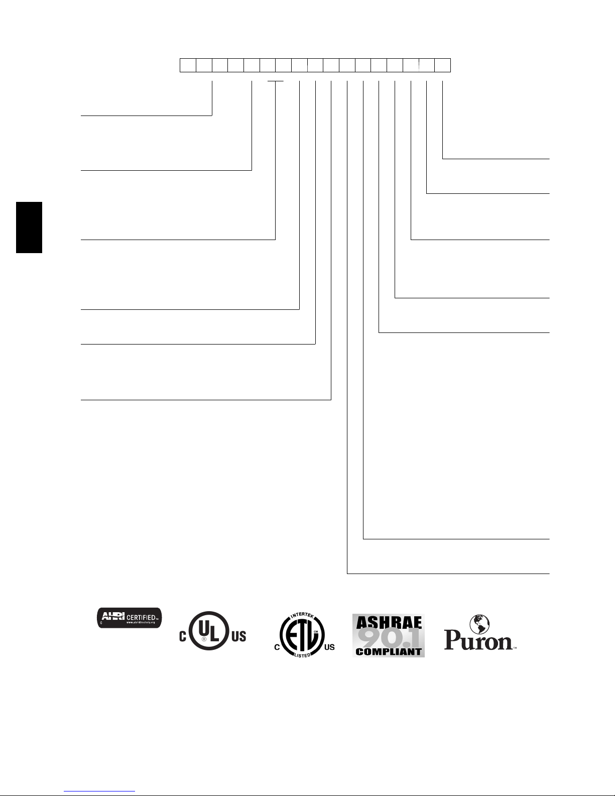
MODEL NUMBER NOMENCLATURE
1234567891011121314151617
5 6 9 J E 1 4 A 0 0 0 G 0 0 A 0 A
_____________
Model Type
569J = Bryant Condensing Unit
Puronr R--- 410A Refrigerant
Voltage Packaging
E = 460/3/60 A=Standard
P = 208/230/3/60 B=LTL
T = 575/3/60
Base Unit Controls
Nominal Tonnage 0=None
07 = 6 Tons 16 = 15 Tons
08 = 7.5 Tons 25 = 20 Tons Electrical Options
12 = 10 Tons A=None
14 = 12.5 Tons C = Non ---Fused Disconnect
Refrigerant Circuit Service Options
A = Single Circuit 0 = Electro--- Mechanical Controls
B = Single Circuit with Low Ambient Controller 1 = Unpowered Convenience Outlet
D=DualCircuit 2 = Powered Convenience Outlet
E = Dual Circuit with Low Ambient controller
Factory Assigned
Factory Assigned 0=Default
0=Default
Coil Options --- Condenser
With All Aluminum --- NOVATION Design
(07--- 16 sizes)
Factory Assigned G=Al/Al
0=Default K = E --- C o a t A l/ A l
T=Al/Alwithlouveredhailguard
W = E ---Coat Al/Al with louvered hail guard
Coil Options --- Condenser
With Round Tube/Plate Fin Design
A=Al/CuStandard
B = P r e --- C o a t e d A l/ C u
C --- E --- C o a t A l / C u
E= Cu/Cu
M=Al/CuStandardwithlouveredhailguard
N=Pre---CoatedAl/Cuwithlouveredhailguard
P = E ---Coat al/Cu with louvered hail guard
R = Cu/Cu --- Louvered hail guard
Use of the AHRI Certified
TM Mark indicates a
manufacturer’s
participation in the
program For verification
of certification for individual
products, go to
www.ahridirectory.org.
569J --- 6 to 12.5 Ton
Factory Assigned
0=Default
the environmentally sound refrigerant
569J --- 15 nd 20 Ton
Certified to ISO 9001
4
Page 5
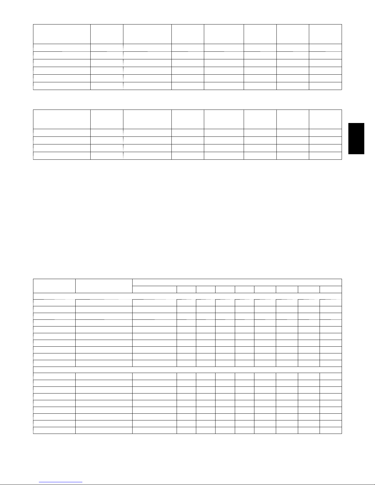
AHRI* CAPACITY RATINGS
UNIT
569J*07A/524J*07 1 1 6 71.0 6.2 11.5 12.2
569J*08A/524J*08 1 1 7.5 92.0 8.2 11.2 11.8
569J*12A/524J*12 1 1 10 117.0 10.4 11.2 12.0
569J*14A/524J*14 1 1 12.5 148.0 13.5 11.0 12.0
569J*16A/524J*16 1* 2 15 184.0 16.4 11.2 13.2
569J*25A/524J25 1* 2 20 240.0 21.8 11.0 11.2
* Single circuit with two (tandem) co mpressors. See application tip #38TIP ---10 ---03 for staging capabilities.
COOLING
CIRCUITS
COMPRESSORS
NOM.
CAPACITY
(TONS)
NET COOLING
CAPACITY
(MBH)
TOTAL
POWER
(kW)
EER IEER
UNIT
569J*12D/524J12 2 2 10 117.0 10.4 11.2 11.6
569J*14D/524J14 2 2 12.5 148.0 13.5 11.0 12.0
569J*16D/524J16 2 2 15 184.0 16.4 11.2 11.8
569J*25D/524J25 2 2 20 240.0 21.8 11.0 11.2
LEGEND
AHRI --- Air C o nditioning, Heating and Refrigeration
Institute
ASHRAE --- American Society of Heating, Refrigerating
and Air Conditioning, Inc.
EER --- Energy Efficiency Ratio
IEER --- Integrated Energy Efficiency Ratio
COOLING
CIRCUITS
COMPRESSORS
NOM.
CAPACITY
(TONS)
NET COOLING
CAPACITY
(MBH)
NOTES
1. Rated in accordance with AHRI Standard 340/360, as
appropriate.
2. Ratings are based on:
Cooling Standard: 80_F(27_C) db, 67_F(19_C) wb
indoor air temp and 95_F(35_C) db outdoor air temp.
IEER Standard: 80_F(27_C) db, 67_F(19_C) wb indoor
air temp and 4 various outdoor temperatures.
3. All units comply wit h ASHRAE 90.1 Energy Standard for
minimum EER and IEER requirements.
TOTAL
POWER
(kW)
EER IEER
SOUND POWER LEVELS, dB
UNIT
569J*07A 1 82 86.4 86.0 79.2 80.2 77.6 72.0 67.9 62.3
569J*08A 1 82 86.8 85.7 80.3 80.3 77.7 72.3 70.2 65.4
569J*12A 1 82 82.8 81.5 79.2 79.4 76.2 72.3 69.4 64.2
569J*14A 1 82 82.9 78.5 77.0 77.0 75.6 75.9 72.3 70.9
569J*16A 1 80 90.3 81.8 78.0 76.7 75.2 70.5 66.4 61.9
569J*25A 1 85 91.0 85.0 80.0 86.0 79.0 73.0 68.0 63.0
569J*12D 2 82 85.2 84.0 81.0 79.5 76.6 72.4 69.3 69.5
569J*14D 2 82 84.7 79.8 78.8 77.6 77.0 72.5 70.3 67.3
569J*16D 2 80 90.3 81.8 78.0 76.7 75.2 70.5 66.4 61.9
569J*25D 2 85 91.0 85.0 80.0 86.0 79.0 73.0 68.0 63.0
569J*07A 1 85 89.3 85.0 82.0 82.7 80.2 75.2 71.0 66.0
569J*08A 1 85 89.3 85.0 82.0 82.7 80.2 75.2 71.0 66.0
569J*12A 1 83 86.6 81.9 85.7 80.0 77.1 74.6 69.2 65.8
569J*12D 2 84 86.3 85.8 81.4 81.9 79.5 75.1 71.9 68.9
569J*14D 2 83 81.7 80.9 82.2 80.4 78.2 73.6 69.7 65.4
569J*16A 2 83 86.7 81.2 78.9 80.4 78.0 74.2 70.2 65.0
569J*16D 2 83 86.7 81.2 78.9 80.4 78.0 74.2 70.2 65.0
569J*25A 2 85 91.0 85.0 80.0 86.0 79.0 73.0 68.0 63.0
569J*25D 2 85 91.0 85.0 80.0 86.0 79.0 73.0 68.0 63.0
LEGEND
dB = Decibel
NOTE: Outdoor sound data is measure in accordance with AHRI standard 270 --- 2008.
COOLING
CIRCUITS
A --- WE I GH T ED 63 125 250 500 1000 2000 4000 8000
N O V AT I O N --- A l l A l u m i n u m C o i l D e s i g n
RTPF --- Round Tube/Plate Fin Coil Design
OUTDOOR SOUND (dB)
569J
5
Page 6
PHYSICAL DATA
Single Circuit Models with NOVATION --- All Aluminum Coil Design
569J*07A 569J*08A 569J*12A 569J*14A 569J*16A
Refrigeration System
# Circuits / # Comp. / Type 1/1/Scroll 1/1/Scroll 1/1/Scroll 1/1/Scroll 1/2/Scroll
R --- 410A charge A/B (lbs) 4.4 4.9 6.3 7.3 12.2
System charge w/ fan coil 8.4 10.2 13.8 18.0 24.6
Metering device TXV TXV TXV TXV TXV
High - -- press. Trip / Reset (psig) 630 / 505 630 / 505 630 / 505 630 / 505 630 / 505
Low ---press. Trip / Reset (psig) 54 / 117 54 / 117 54 / 117 54 / 117 54 / 117
Cond. Coil
Material (Fin/Tube) Al/Al Al/Al Al/Al Al/Al Al/Al
Coil type Novation Novation Novation Novation Novation
Rows / FPI 1/20.3 1/20.3 1/20.3 1/20.3 1/20.3
Tot a l fa ce a re a (f t2 ) 17.5 20.5 25.0 31.8 25.0 x 2
Cond. fan / motor
Qty / Motor drive type 2/direct 2/direct 2/direct 2/direct 3/direct
569J
Note: 569J*25 model is not available with NOVATION coil.
Refrigeration System
# Circuits / # Comp. / Type 1/1/Scroll 1/1/Scroll 1/1/Scroll 1/1/Scroll 1/2/Scroll 1/2/Scroll
R --- 410a charge A/B (lbs) 11.0 13.0 16.0 32.0 32.0 28.0
System charge w/ fan coil* 14.0 17.0 20.0 N/A 43.0 38.0
High - -- press. Trip / Reset (psig) 630 / 505 630 / 505 630 / 505 630 / 505 630 / 505 630 / 505
Low ---press. Trip / Reset (psig) 54 / 117 54 / 117 54 / 117 54 / 117 54 / 117 54 / 117
Cond. Coil
Cond. fan / motor
* Approximate system charge with about 25 ft piping of sizes indicated with matched 524J
Motor HP / RPM 1/4 / 1100 1/4 / 1100 1/4 / 1100 1/4 / 1100 1/4 / 1100
Fan diameter (in) 22 22 22 22 22
Nominal Airflow (cfm) 6,000 6,000 6,000 6,000 10,000
Watts (total) 610 610 610 610 970
Single Circuit Models with RTPF --- Round Tube/Plate Fin Coil Design
569J*07A 569J*08A 569J*12A 569J*14A 569J*16A 569J*25A
Metering device TXV TXV TXV TXV TXV TXV
Material (Fin/Tube) Al/Cu Al/Cu Al/Cu Al/Cu Al/Cu Al/Cu
Coil type RTPF RTPF RTPF RTPF RTPF RTPF
Rows / FPI 2/17 2/17 2/17 3/17 2/17 2/17
Tot a l fa ce a re a (f t2 ) 17.5 17.5 25.1 31.8 23.5 x 2 25.0 x 2
Qty / Motor drive type 2/direct 2/direct 2/direct 2/direct 3/direct 4/direct
Motor HP / RPM 1/4 / 1100 1/4 / 1100 1/4 / 1100 1/4 / 1100 1/4 / 1100 1/4 / 1100
Fan diameter (in) 22 22 22 22 22 22
Nominal Airflow (cfm) 6,000 6,000 6,000 6,000 9,000 12,000
Watts (total) 610 610 610 610 970 1150
6
Page 7
PHYSICAL DATA (CONT.)
Dual Circuit Models with NOVATION --- All Aluminum Coil Design
569J*12D 569J*14D 569J*16D
Refrigeration System
# Circuits / # Comp. / Type 2/2/Scroll 2/2/Scroll 2/2/Scroll
R --- 410A charge A/B (lbs) 3.0 /3.1 3.7/3.9 6.1/6.1
System charge w/ fan coil 7.4 / 7.4 10.8 / 10.8 12.0/12.0
Metering device TXV TXV TXV
High - -- press. Trip / Reset (psig) 630 / 505 630 / 505 630 / 505
Low ---press. Trip / Reset (psig) 54 / 117 54 / 117 54 / 117
Cond. Coil
Material (Fin/Tube)
Coil type Novation Novation Novation
Rows / FPI 1 / 20.3 1 / 20.3 1 / 20.3
Tot a l fa ce a re a (f t2 ) 25.0 31.8 25.0 x 2
Cond. fan / motor
Qty / Motor drive type 2/direct 2/direct 3/direct
Motor HP / RPM 1/4 / 1100 1/4 / 1100 1/4 / 1100
Fan diameter (in) 22 22 22
Nominal Airflow (cfm) 6,000 6,000 10,000
Watts (total) 610 610 970
Note: 569J*25D model is not available with NOVATION coil.
Dual Circuit Models with RTPF --- Round Tube/Plate Fin Coil Design
Refrigeration System
# Circuits / # Comp. / Type 2/2/Scroll 2/2/Scroll 2/2/Scroll 2/2/Scroll
R --- 410a charge A/B (lbs) 8.0 / 8.0 16.0 / 16.0 16.0 / 16.0 14.0 / 14.0
System charge w/ fan coil* 11.0 / 11.0 22.0 / 22.0 22.0 / 22.0 19.0 / 19.0
Metering device TXV TXV TXV TXV
High - -- press. Trip / Reset (psig) 630 / 505 630 / 505 630 / 505 630 / 505
Low ---press. Trip / Reset (psig) 54 / 117 54 / 117 54 / 117 54 / 117
Cond. Coil
Material (Fin/Tube) Al/Cu Al/Cu Al/Cu Al/Cu
Coil type RTPF RTPF RTPF RTPF
Rows / FPI 2/17 3/17 2/17 2/17
total face area (ft2) 25.1 31.8 23.5 x 2 25.0 x 2
Cond. fan / motor
Qty / Motor drive type 2/direct 2/direct 3/direct 4/direct
Motor HP / RPM 1/4 / 1100 1/4 / 1100 1/4 / 1100 1/4 / 1100
Fan diameter (in) 22 22 22 22
Nominal Airflow (cfm) 6,000 6,000 9,000 12,000
Watts (total) 610 610 970 1150
* Approximate system charge with about 25 ft piping of sizes indicated with matched 524J
Al/Al Al/Al Al/Al
569J*12D 569J*14D 569J*16D 569J*25D
569J
7
Page 8
569J
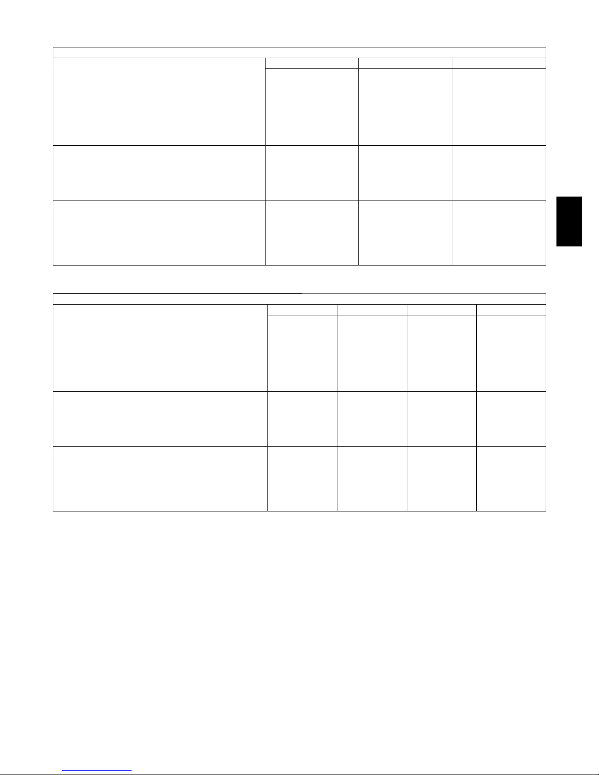
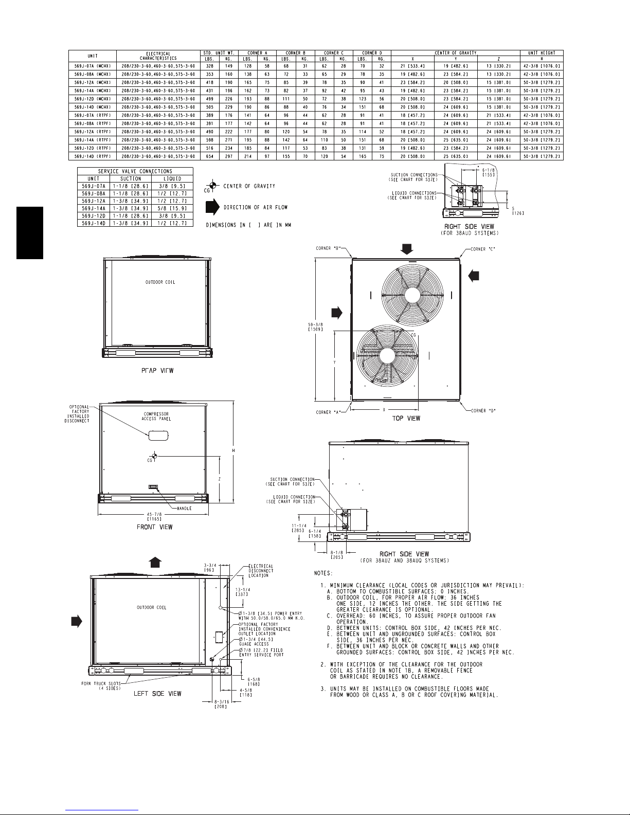
DIMENSIONS
C101212A
8
Page 9
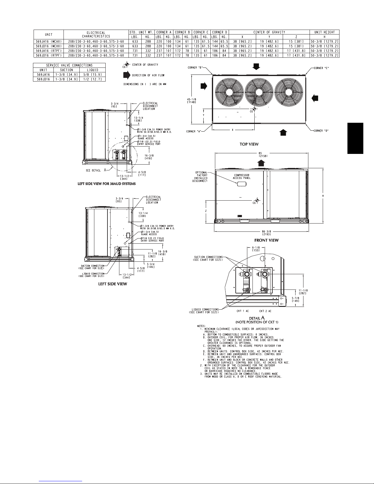
DIMENSIONS (cont.)
569J
C101213
9
Page 10
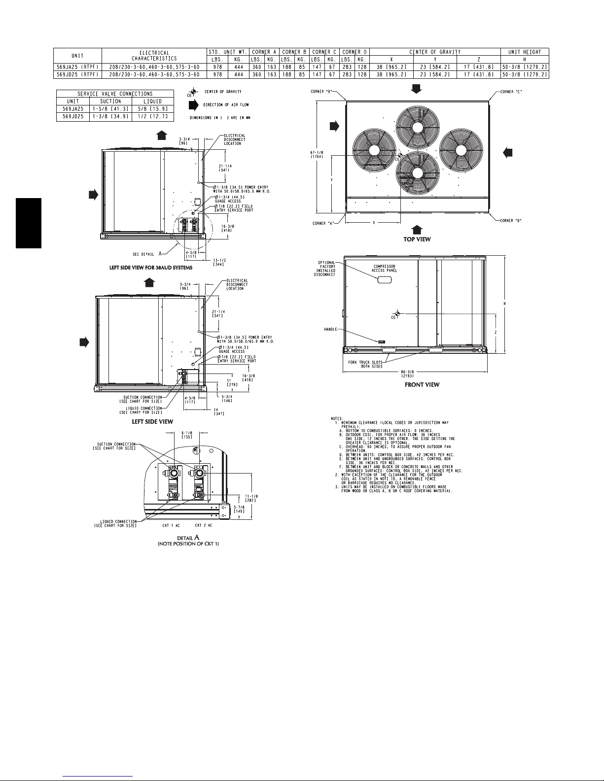
DIMENSIONS (cont.)
UNIT
569JA25 (RTPF) 208/230-3-60,460-3-60,575-3-60 978 444 360 163 188 85 147 67 283 128 38 [965.2] 23 [584.2] 17 [431.8] 50-3/8 [1279.2]
569JD25 (RTPF) 208/230-3-60,460-3-60,575-3-60 978 444 360 163 188 85 147 67 283 128 38 [965.2] 23 [584.2] 17 [431.8] 50-3/8 [1279.2]
SERVICE VALVE CONNECTIONS
UNIT SUCTION LIQUID
569JA25 1-5/8 [41.3] 5/8 [15.9]
569JD25 1-3/8 [34.9] 1/2 [12.7]
ELECTRICAL
CHARACTERISTICS
STD. UNIT WT. CORNER A CORNER B CORNER C CORNER D CENTER OF GRAVITY UNIT HEIGHT
LBS. KG. LBS. KG. LBS. KG. LBS. KG. LBS. KG. X Y Z H
CENTER OF GRAVITY
CG
DIRECTION OF AIR FLOW
DIMENSIONS IN [ ] ARE IN MM
569J
C101214
10
Page 11
OPTIONS AND ACCESSORIES
569J* OPTIONS AND ACCESSORIES
ITEM OPTION* ACCESSORY†
Disconnect Switch (non-fused)} X
Special--- coated Coil Protection X
Convenience Outlet (115-v)** X
Low Ambient Temperature
MotorMaster Ir Control
Wired Condenser Coil Grille (Novation 07 --- 14 models only) X
Louvered Hail Guard X X
Programmable Thermostats X
* Factory-installed option.
† Field-installed accessory.
} Non ---fused disconnect switch cannot be used when unit MOCP electrical rating exceeds 80 amps.
** Powered and non- -- powered versions available
569J* factory-installed options
X X
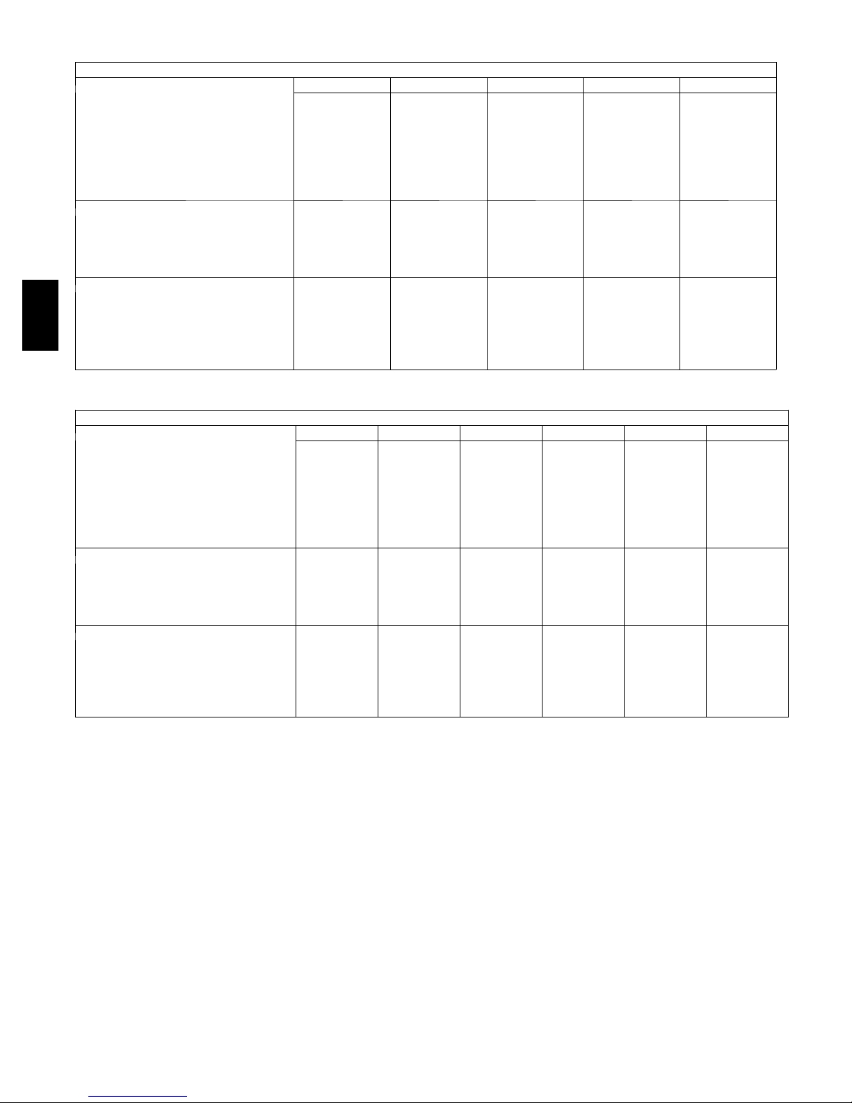
CONDENSER COIL OPTIONS
Coil Coating Application -- Novation Coils
Environment
Coil Description
Alum Fin / Alum Tube X
E --- C o a te d A l / Al X X X X X
NOTE: E ---Coat is only available and must b e used in any non---standard environment listed above.
Standard
N o n --- C o r r o s i v e
Mild Coastal
Moderate
Coastal
Severe
Coastal
Industrial
Industrial &
Coil Coating Application -- Round Tube/Plate Fin Coils
(07,08, 12, 16, 25 models)
Environment
E n v i r o --- S h i e l d ™ Description
Alum Fin / Cu Tube X
P r e --- C o a te d A l / Cu X
E --- C o a te d A l / Cu X X
Cu / Cu X X
NOTE: Refer to the Guide Specifications for further detail.
E-coated aluminum-fin coils have a flexible and durable
epoxy coating uniformly applied to all coil surfaces.
Unlike brittle phenolic dip and bake coatings, E-coating
provides superior protection with unmatched flexibility,
edge coverage, metal adhesion, thermal performance, and
most importantly, corrosion resistance.
E-coated coils provide this protection since all coil
surfaces are completely encapsulated from environmental
contamination. This coating is especially suitable in
industrial environments.
Pre--coated coils (RTPF coils only) provide protection in
mild coastal environments.
Standard
N o n --- C o r r o s i v e
Mild Coastal
Moderate
Coastal
Severe
Coastal
Industrial
Industrial &
–20_F (–29_C) low-ambient temperature kit option
(MotorMaster Ir) controls outdoor-fan motor operation
to maintain the correct head pressure at low outdoor
ambient temperatures.
Louvered hail guard package protects coils against
damage from flying debris and hail.
115-v convenience outlet is used to power electric drills,
lights, and refrigerant recovery machines. This means that
a separate 115-v power supply is no longer necessary.
Non-fused disconnect switch is used to remove power
locally at the condensing unit. This switch also includes a
power lockout capability to protect the service person.
This lockout switch saves the service person time and
effort because there is no need to access a distant
disconnect switch while servicing the unit.
569J
Coastal
Coastal
11
Page 12
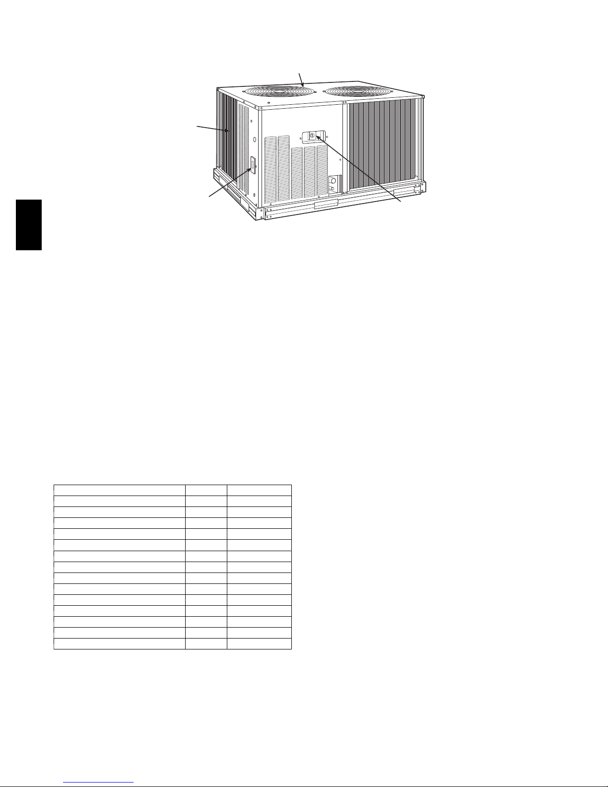
OPTIONS AND ACCESSORIES (cont.)
FACTORY-INSTALLED
COIL PROTECTION
OPTIONAL
FACTORY-INSTALLED
CONVENIENCE OUTLE
(powered and non-powered)
LOW AMBIENT CONTROL
(FACTORY-INSTALLED OR
FIELD-INSTALLED)
T
OPTIONAL
FACTORY-INSTALLED
DISCONNECT SWITCH
569J
569J* field-installed accessories
–20_F (–29_C) low-ambient temperature kit accessory
(MotorMaster Ir) controls outdoor-fan motor operation
to maintain the correct head pressure at low outdoor
ambient temperatures.
Louvered hail guard package protects coils against
damage from flying debris and hail.
Condenser coil grille package protects condensing unit
coil from impact by large objects and vandalism.
Bryant’s line of thermostats provide both programmable
and non-programmable capability with the new
Debonairr line of commercial programmable
thermostats. The Commercial Electronic thermostats
provide 7-day programmable capability for economical
applications.
524J OPTIONS AND ACCESSORIES
ITEM OPTION* ACCESSORY†
Alternate Fan Motors X
Alternate Drives X
CO2Sensors X
Condensate Drain Trap X
Discharge Plenum X
Economizer X
Electric Heat X
Hot Water Heating Coils X
Overhead Suspension Package X
Prepainted Units X
Return Air Grille X
Steam Heating Coil X
Subbase X
UV-C Germicidal Lamp** X
* Factory-installed option.
† Field-installed accessory.
** Contact application engineer.
C101216
524J factory-installed options
Alternate fan motors and drives are available to provide
the widest possible range of performance.
Units constructed of prepainted steel are available from
the factory for applications that require painted units. Unit
color is American Sterling Gray.
524J field-installed accessories
Two-row hot water coils have5/8-in. diameter copper
tubes mechanically bonded to aluminum plate fins. Coils
have non-ferrous headers.
One-row steam coil has 1-in. OD copper tube and
aluminum fins. The Inner Distributing Tube (IDT) design
provides uniform temperatures across the coil face. The
IDT steam coils are especially suited to applications
where sub-freezing air enters the unit.
Electric resistance heat coils have an open-wire design
and are mounted in a rigid frame. Safety cutouts for high
temperature conditions are standard.
Economizer (enthalpy controlled) provides ventilation
air and provides “free” cooling if the outside ambient
temperature and humidity are suitable. The economizer
can also be used in conjunction with Bryant Comfort
System thermostats and CO
air quality requirements. The economizer can be used in
both vertical and horizontal positions.
Discharge plenum directs the air discharge into the
occupied space; integral horizontal and vertical louvers
enable redirection of airflow. This accessory is available
unpainted or painted.
Return-air grille provides a protective barrier over the
return-air opening and gives a finished appearance to units
installed in the occupied space. This accessory is available
unpainted or painted.
sensors to help meet indoor
2
Subbase provides a stable, raised platform and room for
condensate drain connection for floor-mounted units. This
accessory is available unpainted or painted.
12
Page 13

OPTIONS AND ACCESSORIES (cont.)
Overhead suspension package includes necessary
brackets to support units in horizontal installations.
CO
sensors can be used in conjunction with the
2
economizer accessory to help meet indoor air quality
requirements. The sensor signals the economizer to open
when the CO
Bryant Comfort System programmable thermostat can
also be used to override the sensor if the outside-air
temperature is too high or too low.
level in the space exceeds the setpoint. A
2
Condensate drain trap includes an overflow shutoff
switch that can be wired to turn off the unit if the trap
becomes plugged. The kit also includes a wire harness
that can be connected to an alarm if desired. The
transparent trap is designed for easy service and
maintenance.
UV-C germicidal lamps kill mold and fungus that may
grow on evaporator coil and condensate pan surfaces. The
use of UV-C germicidal lamps eliminates the foul odors
that result from mold and fungus growth. These lamps
also provide a self-cleaning function for the evaporator
coil and drain pan. Contact application engineer for info.
569J
13
Page 14
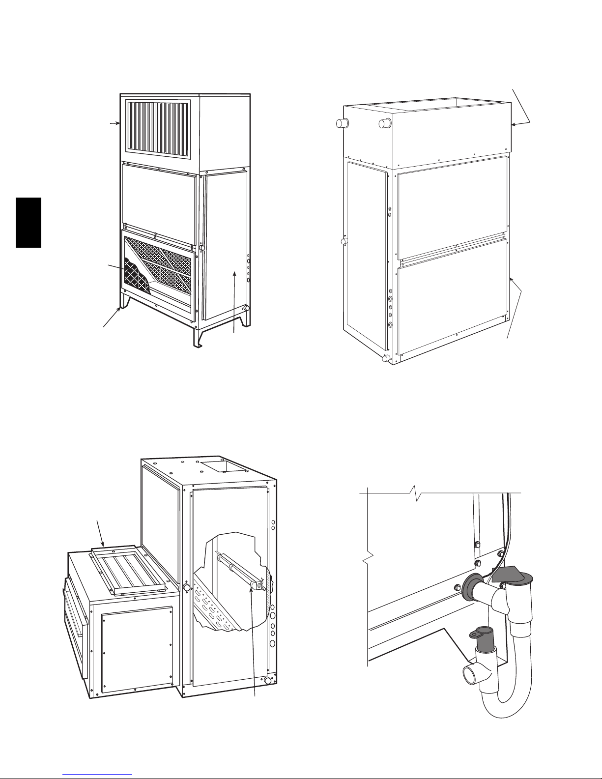
OPTIONS AND ACCESSORIES (cont.)
569J
524J WITH DISCHARGE PLENUM
RETURN-AIR GRILLE AND SUBBASE
DISCHARGE
PLENUM
RETURN-AIR
GRILLE
SUBBASE
FAN
COIL
UNIT
524J WITH HOT WATER OR STEAM COIL
HOT WATER OR
STEAM COIL
FAN COIL
UNIT
524J WITH ECONOMIZER
AND UV-C GERMICIDAL LAMPS
ECONOMIZER
524J WITH CONDENSATE TRAP
UV-C GERMICIDAL LAMPS
C09259
14
Page 15

SELECTION PROCEDURE
Combination ratings for 569J* units matched with 524J
Series air handlers are in this book. If unit is used with an
air handler, use the Bryant Electronic Catalog AHU
(Air-Handling Unit) selection program to obtain combined
ratings.
I. Determine cooling load, evaporator-air
temperature, and quantity.
Given:
Total Cooling Capacity
Required (TC) 121,000 Btuh...................
Sensible Heat Capacity
Required (SHC) 95,000 Btuh...................
Compressor Type Scroll.........................
Temperature Air Entering
Condenser (Edb) 95_F.........................
Temperature Air Entering
Evaporator (db/wb) 80_F db, 67_Fwb............
Evaporator Air Quantity 4,000 cfm.................
External Static Pressure 0.4 in. wg.................
Length of Interconnecting
Refrigerant Piping 25 ft (Linear).................
Power Supply (V-Ph-Hz) 208/230-3-60.............
II. Select condensing unit air-handler combination.
For this example, select a 569J*12 matched with a
524J012 coil. This 569J*12/524J12 condensing unit
air-handler combination provides 122,000 Btuh of total
cooling capacity and 97,200 Btuh of sensible capacity at
the given conditions. If other temperatures or airflow
values are required, interpolate the values from the
combination ratings.
III. Determine sizes of liquid and suction lines.
Enter Refrigerant Piping Sizes table. The sizes shown
are based on an equivalent length of pipe. This
equivalent length is equal to the linear length of pipe
indicated at the top of each sizing column, plus a 50%
allowance for fitting losses. (For a more accurate
determination of actual equivalent length in place of
using the estimated 50% value, refer to Bryant System
Design Manual.) For this example, note in the linear
length column that the proper pipe size is
liquid line and 1
For extended line lengths over 100 feet, contact your
Bryant representative or application engineer.
3
/8in. for the suction line.
1
/2in. for the
IV. Determine fan rpm and bhp (brake horsepower).
Refer to the 524J Air Handler Catalog -- Fan
Performance table. Enter the Air Handler Fan
Performance table at 524J12 at 4000 cfm and move to
the External Static Pressure (ESP) column. Note that the
conditions require 803 rpm at 1.77 bhp.
V. Determine motor and drive.
Enter the Fan Motor Data tables and find the standard
motor for 524J12 unit rated at 2.4 Hp. Since the bhp
required is 1.77, a standard motor satisfies the
requirement and should be used.
Next, find the type of drive that satisfies the 803 rpm
requirement in the Drive Data tables. For the 524J012
unit, the Standard Drive table shows an rpm range of
666-863. Since the rpm required is 803, the standard
drive satisfies the requirement and should be used.
CONTROLS
Operating sequences
When the wall thermostat calls for cooling, terminals G
and Y1 are energized. As a result, the indoor fan contactor
(IFC) and the compressor contactor (C1) are energized,
causing the indoor fan motor (IFM), compressor #1, and
outdoor fans (OFM) to start. The field--supplied and
field--installed liquid line valve also opens, allowing the
system to function in Cooling mode.
If the unit has 2 stages of cooling, the wall thermostat will
additionally energize Y2. The Y2 signal will energize
compressor contactor #2 (C2), causing compressor #2 to
start.
Regardless of the number of stages, the field--supplied
liquid line valve shall opens and the outdoor fan
motors(OFM) runs continuously while unit is cooling.
When cooling demand decrease, the thermostat will
de--energize Y2. Y2 signal will de--energize compressor
contactor #2 (C2), causing compressor #2 to stop.
When cooling demand has been satisfied, the thermostat
will de--energize Y1, and G terminals. Y1 and G signal
will de--energize compressor contactor #1 (C1), causing
compressor #1 to stop. If the wall thermostat is set to
continuous (CONT), the indoor fan motor will continue
to operate. Otherwise, the indoor fan motor will stop.
The outdoor fan motors (OFM) will turn off and
field--supplied liquid line valve shall close , minimizing
the potential for refrigerant migration.
569J
15
Page 16
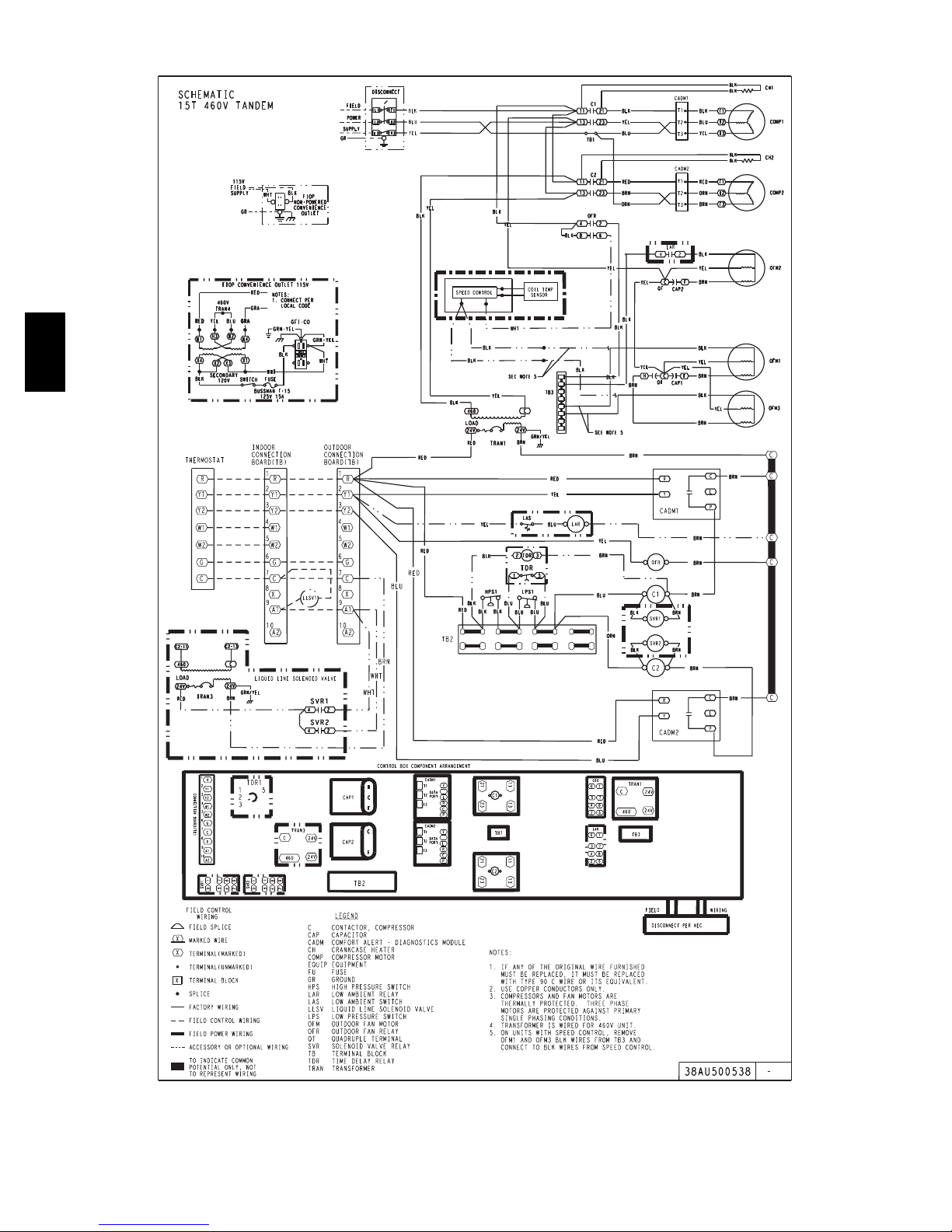
569J
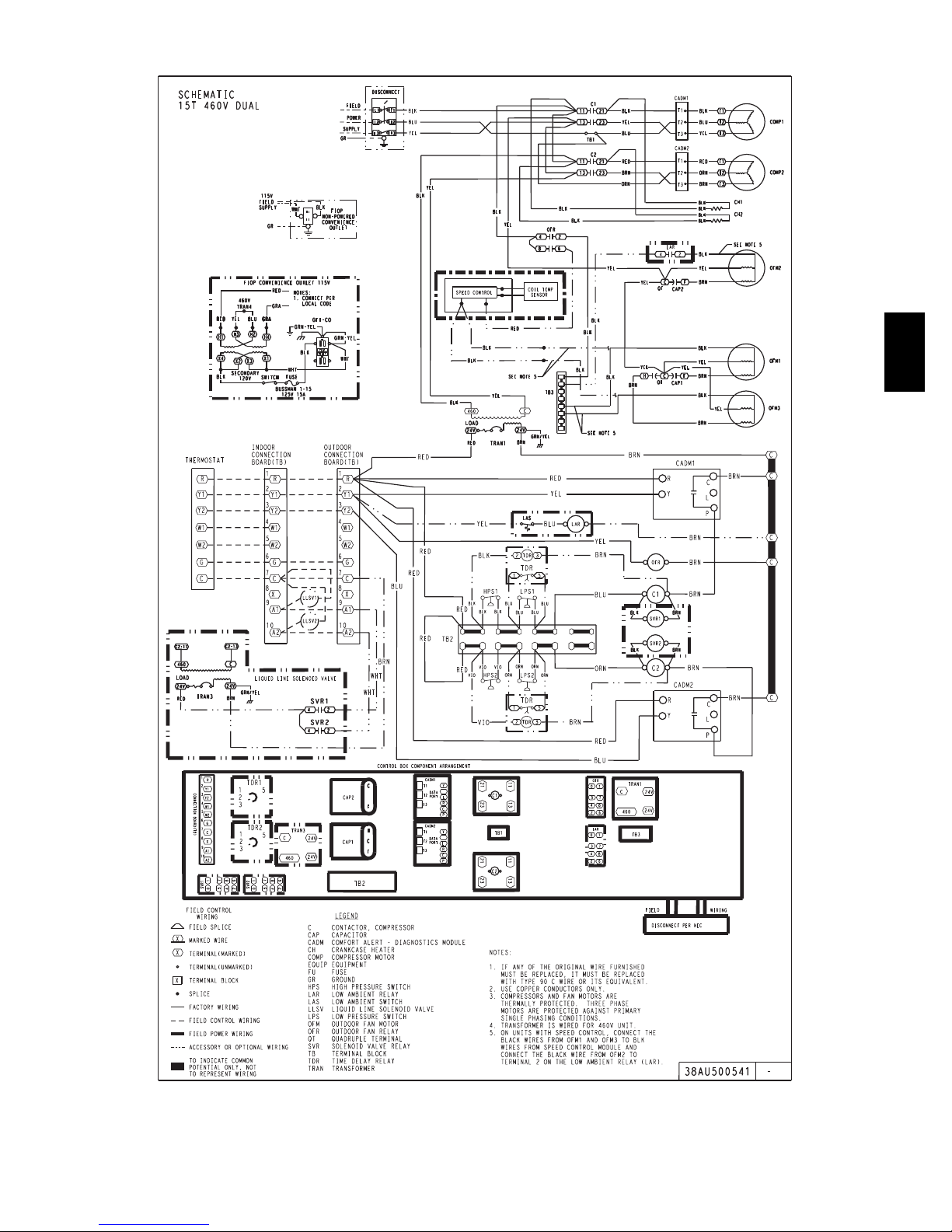
TYPICAL WIRING SCHEMATIC
C09624
Typical 569J*16 Single Circuit
16
Page 17
TYPICAL WIRING SCHEMATIC (cont.)
569J
C09627
Typical 569J*16 Dual Circuit
17
Page 18

PERFORMANCE DATA
569J*07A CONDENSER ONLY RATINGS
SST (_F)
TC 46.7 45.1 41.7 39.8 37.9 33.9
20
25
30
35
569J
40
45
50
NOTE:
Condensing unit only ratings are at 45
kW 4.04 4.27 4.77 5.04 5.32 5.93
SDT 91.6 96.4 105.9 110.6 115.3 124.7
TC 51.8 50.2 46.5 44.6 42.6 38.4
kW 4.06 4.29 4.79 5.05 5.33 5.95
SDT 92.7 97.5 106.9 111.6 116.3 125.6
TC 57.0 55.2 51.4 49.4 47.3 42.9
kW 4.07 4.30 4.80 5.07 5.35 5.96
SDT 93.9 98.6 108.1 112.7 117.4 126.7
TC 62.7 60.8 56.8 54.6 52.4 47.8
kW 4.09 4.32 4.81 5.08 5.36 5.98
SDT 95.1 99.8 109.2 113.9 118.6 127.8
TC 68.7 66.7 62.5 60.2 57.9 53.0
kW 4.11 4.34 4.83 5.10 5.38 5.99
SDT 96.5 101.1 110.5 115.1 119.7 128.8
TC 75.2 73.1 68.5 66.2 63.7 58.6
kW 4.13 4.36 4.84 5.10 5.38 5.99
SDT 97.9 102.5 111.8 116.3 120.9 129.9
TC 82.2 79.9 75.1 72.5 69.9 64.4
kW 4.15 4.37 4.85 5.12 5.39 6.00
SDT 99.4 104.0 113.1 117.6 122.2 131.1
AIR TEMPERATURE ENTERING CONDENSER (_F)
80 85 95 100 105 115
_FSSTand95_F entering --- air temperature. EER = 13.1
569J*08A CONDENSER ONLY RATINGS
SST (_F)
TC 65.2 63.2 59.1 57.0 54.8 50.5
20
25
30
35
40
45
50
NOTE:
Condensing unit only ratings are at 45
LEGEND:
k W --- C om pr es so r Po we r
SDT --- Saturated Discharge Temperature at Compressor (
SST - -- Saturated Suction T emperature (
TC --- Gross Co o ling Capacity ( 1000 Btuh)
kW 5.04 5.33 5.98 6.34 6.73 7.60
SDT 95.3 100.2 109.8 114.7 119.5 129.2
TC 71.5 69.4 65.0 62.8 60.5 55.9
kW 5.12 5.42 6.07 6.42 6.81 7.66
SDT 96.4 101.2 110.8 115.6 120.4 129.9
TC 77.8 75.5 70.9 68.5 66.2 61.3
kW 5.22 5.51 6.16 6.51 6.89 7.74
SDT 97.6 102.4 111.9 116.6 121.3 130.7
TC 84.8 82.4 77.5 75.0 72.4 67.2
kW 5.32 5.61 6.26 6.61 6.99 7.83
SDT 98.8 103.5 112.9 117.6 122.3 131.6
TC 92.3 89.7 84.5 81.8 79.0 73.5
kW 5.44 5.73 6.37 6.72 7.10 7.94
SDT 100.1 104.8 114.2 118.8 123.5 132.7
TC 100.3 97.5 91.9 89.0 86.1 80.1
kW 5.57 5.86 6.50 6.85 7.23 8.07
SDT 101.6 106.2 115.5 120.2 124.8 133.9
TC 108.7 105.8 99.8 96.7 93.6 87.3
kW 5.71 6.00 6.64 7.00 7.38 8.21
SDT 103.1 107.8 117.0 121.6 126.2 135.3
80 85 95 100 105 115
_FSSTand95_F entering --- air temperature. EER = 13.0
_F)
AIR TEMPERATURE ENTERING CONDENSER (_F)
_F)
18
Page 19

PERFORMANCE DATA (cont.)
569J*12A CONDENSER ONLY RATINGS
SST (_F)
TC 78.0 75.4 70.1 67.3 64.6 58.9
20
25
30
35
40
45
50
NOTE:
Condensing unit only ratings are at 45
kW 6.03 6.44 7.31 7.76 8.23 9.21
SDT 94.0 98.7 108.2 113.0 117.7 127.2
TC 86.4 83.6 77.9 74.9 72.0 66.0
kW 6.11 6.53 7.41 7.87 8.36 9.36
SDT 95.2 100.0 109.4 114.2 118.9 128.2
TC 94.7 91.8 85.6 82.5 79.4 73.0
kW 6.20 6.62 7.51 7.98 8.47 9.49
SDT 96.6 101.3 110.7 115.4 120.0 129.2
TC 104.0 100.8 94.3 90.9 87.6 80.7
kW 6.30 6.71 7.61 8.09 8.58 9.62
SDT 98.1 102.7 112.0 116.6 121.2 130.4
TC 113.9 110.4 103.4 99.9 96.2 88.9
kW 6.39 6.81 7.71 8.20 8.70 9.75
SDT 99.5 104.2 113.4 117.9 122.5 131.6
TC 124.3 120.6 113.1 109.2 105.4 97.5
kW 6.49 6.92 7.83 8.32 8.82 9.89
SDT 101.1 105.7 114.8 119.4 123.9 132.9
TC 135.4 131.4 123.3 119.2 115.0 106.5
kW 6.61 7.04 7.96 8.45 8.96 10.03
SDT 102.8 107.3 116.4 120.9 125.4 134.3
AIR TEMPERATURE ENTERING CONDENSER (_F)
80 85 95 100 105 115
569J
_FSSTand95_F entering --- air temperature. EER = 13.5
569J*12D Dual Circuit CONDENSER ONLY RATINGS
SST (_F)
TC 75.29 69.95 67.18 64.32 58.42 55.21
20
25
30
35
40
45
50
NOTE:
Condensing unit only ratings are at 45
LEGEND:
k W --- C om pr es so r Po we r
SDT --- Saturated Discharge Temperature at Compressor (
SST - -- Saturated Suction T emperature (
TC --- Gross Co o ling Capacity ( 1000 Btuh)
kW 6.88 7.89 8.43 8.96 10.04 10.53
SDT 102.3 111.4 116.1 120.5 129.6 133.7
TC 83.12 77.31 74.32 71.28 64.99 61.76
kW 6.97 7.98 8.53 9.07 10.18 10.73
SDT 103.6 112.6 117.3 121.8 130.7 135.1
TC 91.41 85.21 81.99 78.76 72.08 68.58
kW 7.06 8.08 8.63 9.18 10.31 10.87
SDT 104.9 114.0 118.5 122.9 131.8 136.1
TC 100.35 93.69 90.26 86.76 85.11 75.65
kW 7.15 8.18 8.73 9.29 10.42 10.99
SDT 106.3 115.2 119.8 124.2 132.9 137.1
TC 109.90 102.58 98.84 95.06 87.13 83.07
kW 7.25 8.29 8.83 9.39 10.54 11.12
SDT 107.6 116.6 121.0 125.4 134.0 138.2
TC 119.86 111.84 107.74 103.56 95.02 90.54
kW 7.36 8.39 8.93 9.49 10.64 11.22
SDT 109.0 117.9 122.3 126.6 135.1 139.2
TC 130.20 121.39 116.90 112.33 103.07 98.17
kW 7.48 8.51 9.04 9.60 10.75 11.33
SDT 110.5 119.2 123.5 127.8 136.2 140.2
85 95 100 105 115 120
_FSSTand95_F entering --- air temperature. EER = 13.0
_F)
AIR TEMP ENT CONDENSER (_F)
_F)
19
Page 20

PERFORMANCE DATA (cont.)
569J*14A CONDENSER ONLY RATINGS
SST (_F)
TC 100.8 97.4 90.3 86.6 83.0 75.5
20
25
30
35
569J
40
45
50
NOTE:
Condensing unit only ratings are at 45
kW 8.48 8.97 10.00 10.53 11.07 12.19
SDT 98.0 102.6 111.8 116.4 120.9 130.0
TC 111.8 108.1 100.5 96.6 92.7 84.7
kW 8.66 9.15 10.20 10.75 11.31 12.47
SDT 99.6 104.1 113.2 117.7 122.3 131.3
TC 122.9 118.9 110.7 106.6 102.4 93.9
kW 8.84 9.35 10.41 10.97 11.55 12.75
SDT 101.3 105.8 114.8 119.3 123.8 132.7
TC 134.9 130.6 121.9 117.4 113.0 103.8
kW 9.05 9.55 10.64 11.21 11.80 13.03
SDT 103.1 107.6 116.5 120.9 125.4 134.2
TC 147.7 143.0 133.7 128.9 124.1 114.3
kW 9.27 9.78 10.88 11.47 12.07 13.32
SDT 105.1 109.5 118.3 122.8 127.1 135.8
TC 161.1 156.2 146.1 141.0 135.8 125.4
kW 9.51 10.03 11.15 11.73 12.34 13.61
SDT 107.2 111.6 120.3 124.7 129.0 137.5
TC 175.4 170.1 159.3 153.8 148.3 137.1
kW 9.78 10.30 11.42 12.02 12.63 13.92
SDT 109.5 113.8 122.4 126.7 130.9 139.4
AIR TEMPERATURE ENTERING CONDENSER (_F)
80 85 95 100 105 115
_FSSTand95_F entering --- air temperature. EER = 12.0
569J*14D Dual Circuit CONDENSER ONLY RATINGS
SST (_F)
TC 93.24 86.18 82.60 78.94 71.54 67.78
20
25
30
35
40
45
50
NOTE:
Condensing unit only ratings are at 45
LEGEND:
k W --- C om pr es so r Po we r
SDT --- Saturated Discharge Temperature at Compressor (
SST - -- Saturated Suction T emperature (
TC --- Gross Co o ling Capacity ( 1000 Btuh)
kW 9.22 10.36 10.96 11.56 12.76 13.37
SDT 104.4 113.3 117.8 122.2 130.9 135.2
TC 103.39 95.91 92.05 88.15 80.16 76.08
kW 9.42 10.60 11.21 11.83 13.10 13.73
SDT 106.1 114.9 119.3 123.7 132.3 136.6
TC 114.29 106.19 102.04 97.79 89.15 84.74
kW 9.63 10.84 11.46 12.10 13.41 14.07
SDT 107.8 116.6 120.9 125.3 133.8 138.0
TC 125.69 116.93 112.44 107.84 105.72 93.69
kW 9.84 11.07 11.71 12.36 13.70 14.38
SDT 109.5 118.2 122.6 126.8 135.2 139.4
TC 137.57 128.07 123.21 118.21 108.08 102.90
kW 10.05 11.30 11.95 12.61 13.98 14.68
SDT 111.3 119.9 124.2 128.4 136.7 140.8
TC 149.86 139.53 134.26 128.83 117.83 112.22
kW 10.27 11.53 12.18 12.85 14.24 14.95
SDT 113.1 121.6 125.8 130.0 138.1 142.1
TC 162.51 151.29 145.56 139.64 127.71 121.55
kW 10.50 11.76 12.42 13.09 14.48 15.20
SDT 114.9 123.3 127.5 131.6 139.6 143.5
85 95 100 105 115 120
_FSSTand95_F entering --- air temperature. EER = 13.0
_F)
AIR TEMP ENT CONDENSER (_F)
_F)
20
Page 21

PERFORMANCE DATA (cont.)
569J*16A CONDENSER ONLY RATINGS
SST (_F)
TC 125.5 121.8 114.2 106.6 99.7 79.7
20
25
30
35
40
45
50
NOTE:
Condensing unit only ratings are at 45
kW 10.5 11.2 12.6 14.2 16.0 17.5
SDT 98.6 103.4 113.0 122.7 134.9 136.0
TC 138.7 134.7 126.5 118.1 109.3 98.5
kW 10.7 11.4 12.8 14.3 16.0 17.9
SDT 100.0 104.7 114.2 123.6 132.9 140.5
TC 152.9 148.6 139.8 130.7 120.9 104.9
kW 10.9 11.6 13.0 14.6 16.2 17.8
SDT 101.4 106.2 115.5 125.0 133.6 139.4
TC 168.2 163.5 154.1 144.2 133.6 121.2
kW 11.2 11.8 13.2 14.8 16.5 18.1
SDT 102.9 107.5 117.0 126.2 134.8 142.1
TC 184.9 179.4 169.3 158.7 147.6 135.1
kW 11.5 12.0 13.5 15.1 16.8 18.5
SDT 105.2 108.9 118.5 127.7 136.7 144.5
TC 202.1 196.7 185.7 174.3 162.5 150.4
kW 11.7 12.4 13.9 15.6 17.5 19.6
SDT 106.4 111.2 120.9 130.7 140.4 150.2
TC 220.6 214.7 202.1 190.0 174.6 159.6
kW 11.9 12.6 13.9 15.4 16.9 18.5
SDT 107.2 111.7 120.4 129.4 136.9 144.9
80 85 95 105 115 125
_FSSTand95_F entering --- air temperature. EER = 12.7
AIR TEMPERATURE ENTERING CONDENSER (_F)
569J
569J*16D Dual Circuit CONDENSER ONLY RATINGS
SST (_F)
TC 127.6 123.7 116.0 108.1 99.7 90.2
20
25
30
35
40
45
50
NOTE:
Condensing unit only ratings are at 45
LEGEND:
k W --- C om pr es so r Po we r
SDT --- Saturated Discharge Temperature at Compressor (
SST - -- Saturated Suction T emperature (
TC --- Gross Co o ling Capacity ( 1000 Btuh)
kW 10.0 10.6 11.9 13.4 14.9 16.6
SDT 96.0 100.5 109.8 119.2 128.3 137.0
TC 140.9 136.7 128.3 119.5 110.4 101.2
kW 10.0 10.6 11.9 13.4 14.9 16.6
SDT 96.0 100.5 109.8 119.2 128.3 137.0
TC 155.0 150.5 141.3 132.0 122.3 111.4
kW 10.4 11.0 12.3 13.7 15.3 17.0
SDT 98.7 103.3 112.4 121.5 130.6 139.1
TC 170.1 165.3 155.4 145.2 134.4 123.3
kW 10.6 11.2 12.5 14.0 15.5 17.2
SDT 100.1 104.7 113.8 122.8 131.7 140.4
TC 186.3 181.0 170.3 159.0 147.3 134.9
kW 10.8 11.4 12.8 14.2 15.8 17.4
SDT 101.6 106.1 115.1 124.0 132.8 141.4
TC 203.4 197.6 185.7 173.5 160.6 147.2
kW 11.1 11.7 13.0 14.4 16.0 17.6
SDT 103.2 107.6 116.5 125.4 134.0 142.5
TC 221.4 214.9 202.0 188.6 174.5 159.7
kW 11.4 12.0 13.3 14.7 16.2 17.9
SDT 104.8 109.2 118.0 126.7 135.2 143.5
80 85 95 105 115 125
_FSSTand95_F entering --- air temperature. EER = 13.0
_F)
AIR TEMPERATURE ENTERING CONDENSER (_F)
_F)
21
Page 22

PERFORMANCE DATA (cont.)
569J*25A CONDENSER ONLY RATINGS
SST (_F)
TC 159.2 154.5 144.5 133.9 122.5 110.2
20
25
30
35
569J
40
45
50
NOTE:
Condensing unit only ratings are at 45
kW 13.0 13.7 15.3 17.1 19.2 21.5
SDT 97.3 101.8 110.6 119.3 127.9 136.5
TC 176.1 171.0 160.2 148.8 136.5 123.2
kW 13.2 14.0 15.6 17.4 19.5 21.8
SDT 98.9 103.3 112.0 120.7 129.2 137.6
TC 194.2 188.6 176.9 164.5 151.3 136.9
kW 13.5 14.3 15.9 17.7 19.7 22.0
SDT 100.6 104.9 113.6 122.1 130.5 138.8
TC 213.5 207.4 194.7 181.2 166.8 151.2
kW 13.8 14.6 16.2 18.0 20.0 22.3
SDT 102.4 106.7 115.2 123.6 131.9 140.1
TC 234.1 227.4 213.5 198.8 183.1 166.1
kW 14.2 14.9 16.5 18.3 20.3 22.6
SDT 104.3 108.5 116.9 125.2 133.3 141.4
TC 255.9 248.6 233.3 217.3 200.1 181.7
kW 14.6 15.3 16.9 18.7 20.7 22.9
SDT 106.3 110.5 118.7 126.8 134.9 142.7
TC 279.0 270.9 254.2 236.7 218.1 197.8
kW 15.1 15.8 17.3 19.1 21.1 23.2
SDT 108.5 112.5 120.6 128.6 136.5 144.1
80 85 95 105 115 125
_FSSTand95_F entering --- air temperature. EER = 12.9
AIR TEMPERATURE ENTERING CONDENSER (_F)
569J*25D Dual Circuit CONDENSER ONLY RATINGS
SST (_F)
TC 160.3 155.5 145.3 134.3 122.5 109.6
20
25
30
35
40
45
50
NOTE:
Condensing unit only ratings are at 45
LEGEND:
k W --- C om pr es so r Po we r
SDT --- Saturated Discharge Temperature at Compressor (
SST - -- Saturated Suction T emperature (
TC --- Gross Co o ling Capacity ( 1000 Btuh)
kW 12.7 13.4 15.0 16.8 18.8 21.1
SDT 97.0 101.5 110.3 119.1 127.7 136.3
TC 177.2 171.9 160.8 149.0 136.3 122.3
kW 12.7 13.4 15.0 16.8 18.8 21.1
SDT 97.0 101.5 110.3 119.1 127.7 136.3
TC 195.1 189.4 177.4 164.5 150.7 135.6
kW 13.2 13.9 15.5 17.3 19.3 21.5
SDT 100.3 104.6 113.3 121.8 130.3 138.6
TC 214.3 208.0 194.9 180.9 165.9 149.5
kW 13.5 14.3 15.8 17.6 19.6 21.8
SDT 102.1 106.3 114.9 123.3 131.7 139.8
TC 234.6 227.7 213.4 198.2 181.7 163.9
kW 13.9 14.6 16.2 17.9 19.9 22.1
SDT 104.0 108.2 116.6 124.9 133.1 141.1
TC 256.3 258.7 242.3 224.9 206.2 186.1
kW 14.3 15.2 16.7 18.5 20.4 22.5
SDT 106.0 111.1 119.2 127.4 135.4 143.1
TC 279.1 272.0 254.7 236.3 216.6 195.4
kW 14.7 15.5 17.0 18.7 20.6 22.7
SDT 108.1 112.3 120.4 128.4 136.4 143.9
80 85 95 105 115 125
_FSSTand95_F entering --- air temperature. EER = 13.0
_F)
AIR TEMPERATURE ENTERING CONDENSER (_F)
_F)
22
Page 23

PERFORMANCE DATA (cont.)
569J*07A -- 524J*07 COMBINATION RATINGS
AMBIENT TEMPERATURE
85 95 105 115 125
EA (db) EA (db) EA (db) EA (db) EA (db)
75 80 85 75 80 85 75 80 85 75 80 85 75 80 85
THC 65.8 65.8 74.1 63.4 63.4 71.4 60.7 60.7 68.3 58.3 58.3 65.7 54.7 54.7 61.6
58
SHC 57.4 65.8 74.1 55.3 63.4 71.4 53.0 60.7 68.3 50.9 58.3 65.7 47.8 54.7 61.6
THC 68.1 68.1 70.7 65.2 65.2 69.2 62.0 62.0 67.6 58.1 58.1 65.7 54.6 54.6 55.4
62
SHC 51.9 61.3 70.7 50.4 59.8 69.2 48.9 58.3 67.6 47.1 56.4 65.7 36.3 45.9 55.4
THC 74.0 74.0 74.0 70.9 70.9 70.9 67.3 67.3 67.3 63.4 63.4 63.4 56.7 56.7 56.7
67
EA (wb)
1800 Cfm
EA (wb)
2100 Cfm
EA (wb)
2400 Cfm
EA (wb)
2700 Cfm
EA (wb)
3000 Cfm
--- Not operational
THC --- Total Cooling Capacity, Gross (1,000 Btuh)
SHC --- Sensible Cooling Capacity, Gross (1,000 Btuh)
SHC 42.3 51.8 61.3 41.0 50.5 59.9 39.5 49.0 58.4 37.9 47.3 56.8 35.3 44.9 54.4
THC 80.7 80.7 80.7 77.3 77.3 77.3 73.6 73.6 73.6 69.4 69.4 69.4 63.2 63.2 63.2
72
SHC 32.7 42.2 51.8 31.4 40.9 50.4 30.0 39.5 49.0 28.4 37.9 47.4 26.2 35.7 45.3
THC --- 86.2 86.2 --- 82.6 82.6 --- 78.6 78.6 --- 74.3 74.3 --- 70.7 70.7
76
SHC --- 34.5 44.3 --- 33.2 43.0 --- 31.8 41.6 --- 30.3 40.0 --- 29.0 38.7
THC 69.0 69.0 77.8 66.5 66.5 74.9 63.7 63.7 71.8 61.2 61.2 69.0 --- --- ---
58
SHC 60.3 69.0 77.8 58.0 66.5 74.9 55.6 63.7 71.8 53.5 61.2 69.0 --- --- ---
THC 70.2 70.2 77.1 67.2 67.2 75.5 64.0 64.0 73.6 60.4 60.4 70.7 --- --- ---
62
SHC 55.7 66.4 77.1 54.2 64.8 75.5 52.5 63.0 73.6 50.2 60.4 70.7 --- --- ---
THC 75.9 75.9 75.9 72.6 72.6 72.6 68.9 68.9 68.9 64.8 64.8 64.8 59.1 59.1 59.9
67
SHC 44.8 55.7 66.5 43.4 54.3 65.1 41.9 52.8 63.6 40.3 51.1 62.0 38.1 49.0 59.9
THC 82.5 82.5 82.5 79.0 79.0 79.0 75.2 75.2 75.2 70.9 70.9 70.9 63.9 63.9 63.9
72
SHC 33.7 44.6 55.5 32.4 43.3 54.2 31.0 41.8 52.7 29.4 40.3 51.1 26.9 37.9 48.8
THC --- 88.1 88.1 --- 84.3 84.3 --- 80.2 80.2 --- 75.5 75.5 --- 71.8 71.8
76
SHC --- 35.8 47.0 --- 34.5 45.6 --- 33.0 44.2 --- 31.4 42.5 --- 30.2 41.2
THC 71.7 71.7 80.8 69.0 69.0 77.8 66.1 66.1 74.5 62.6 62.6 70.6 58.9 58.9 66.3
58
SHC 62.6 71.7 80.8 60.3 69.0 77.8 57.7 66.1 74.5 54.7 62.6 70.6 51.4 58.9 66.3
THC 72.0 72.0 82.7 69.1 69.1 80.8 66.2 66.2 77.4 63.0 63.0 73.6 --- --- ---
62
SHC 59.0 70.9 82.7 57.4 69.1 80.8 55.0 66.2 77.4 52.3 63.0 73.6 --- --- ---
THC 77.3 77.3 77.3 74.0 74.0 74.0 70.2 70.2 70.2 66.1 66.1 66.9 62.5 62.5 65.0
67
SHC 47.1 59.3 71.5 45.7 57.9 70.1 44.2 56.4 68.6 42.6 54.7 66.9 41.0 53.0 65.0
THC 84.0 84.0 84.0 80.4 80.4 80.4 76.4 76.4 76.4 71.8 71.8 71.8 67.5 67.5 67.5
72
SHC 34.6 46.9 59.1 33.3 45.5 57.8 31.9 44.1 56.3 30.2 42.4 54.6 28.7 40.8 52.9
THC --- 89.5 89.5 --- 85.7 85.7 --- 81.4 81.4 --- 76.7 76.7 --- --- ---
76
SHC --- 36.9 49.4 --- 35.6 48.1 --- 34.2 46.6 --- 32.6 45.0 --- --- ---
THC 73.9 73.9 83.3 71.2 71.2 80.2 68.1 68.1 76.7 64.8 64.8 73.0 58.6 58.6 66.0
58
SHC 64.6 73.9 83.3 62.2 71.2 80.2 59.5 68.1 76.7 56.5 64.8 73.0 51.2 58.6 66.0
THC 74.0 74.0 86.5 71.3 71.3 83.3 68.2 68.2 79.7 64.8 64.8 75.8 --- --- ---
62
SHC 61.5 74.0 86.5 59.2 71.3 83.3 56.6 68.2 79.7 53.8 64.8 75.8 --- --- ---
THC 78.5 78.5 78.5 75.1 75.1 75.1 71.2 71.2 73.2 67.0 67.0 71.5 63.2 63.2 69.4
67
SHC 49.3 62.7 76.2 47.9 61.3 74.8 46.4 59.8 73.2 44.7 58.1 71.5 43.0 56.2 69.4
THC 85.1 85.1 85.1 81.4 81.4 81.4 77.3 77.3 77.3 72.6 72.6 72.6 65.3 65.3 65.3
72
SHC 35.5 49.0 62.5 34.2 47.6 61.1 32.7 46.1 59.6 31.1 44.5 57.9 28.6 42.2 55.7
THC --- 90.7 90.7 --- 86.7 86.7 --- 82.3 82.3 --- --- --- --- --- ---
76
SHC --- 38.1 51.8 --- 36.7 50.4 --- 35.3 48.9 --- --- --- --- --- ---
THC 75.9 75.9 85.5 73.0 73.0 82.3 69.8 69.8 78.7 66.3 66.3 74.7 62.4 62.4 70.4
58
SHC 66.3 75.9 85.5 63.8 73.0 82.3 61.0 69.8 78.7 57.9 66.3 74.7 54.5 62.4 70.4
THC 75.9 75.9 88.8 73.1 73.1 85.4 69.9 69.9 81.7 66.4 66.4 77.6 60.2 60.2 70.4
62
SHC 63.1 75.9 88.8 60.7 73.1 85.4 58.0 69.9 81.7 55.1 66.4 77.6 50.0 60.2 70.4
THC 79.5 79.5 80.7 76.0 76.0 79.3 72.1 72.1 77.6 67.9 67.9 75.7 63.7 63.7 73.5
67
SHC 51.4 66.0 80.7 49.9 64.6 79.3 48.4 63.0 77.6 46.7 61.2 75.7 44.8 59.2 73.5
THC 86.1 86.1 86.1 82.3 82.3 82.3 78.0 78.0 78.0 73.3 73.3 73.3 69.6 69.6 69.6
72
SHC 36.3 51.0 65.8 35.0 49.7 64.4 33.5 48.1 62.8 31.9 46.5 61.1 30.5 44.9 59.3
THC --- 91.6 91.6 --- 87.6 87.6 --- --- --- --- --- --- --- --- ---
76
SHC --- 39.1 54.0 --- 37.8 52.7 --- --- --- --- --- --- --- --- ---
569J
23
Page 24

PERFORMANCE DATA (cont.)
569J*07A -- 524J*08 COMBINATION RATINGS
AMBIENT TEMPERATURE
85 95 105 115 125
EA (db) EA (db) EA (db) EA (db) EA (db)
75 80 85 75 80 85 75 80 85 75 80 85 75 80 85
THC 71.6 71.6 80.7 69.1 69.1 77.9 66.2 66.2 74.6 63.2 63.2 72.2 --- --- ---
58
SHC 62.5 71.6 80.7 60.3 69.1 77.9 57.8 66.2 74.6 55.0 63.2 72.2 --- --- ---
THC 72.5 72.5 81.5 69.6 69.6 79.6 66.6 66.6 76.6 63.2 63.2 73.2 --- --- ---
62
SHC 58.5 70.0 81.5 56.9 68.2 79.6 54.6 65.6 76.6 52.1 62.7 73.2 --- --- ---
THC 78.1 78.1 78.1 74.8 74.8 74.8 71.2 71.2 71.2 67.0 67.0 67.7 60.9 60.9 64.5
67
EA (wb)
2250 Cfm
569J
EA (wb)
2600 Cfm
EA (wb)
3000 Cfm
EA (wb)
3400 Cfm
EA (wb)
3750 Cfm
--- Not operational
THC --- T otal Cooling Capacity, Gross (1,000 Btuh)
SHC --- Sensible Cooling Capacity, Gross (1,000 Btuh)
SHC 46.9 58.7 70.5 45.6 57.4 69.1 44.1 55.9 67.6 42.4 54.2 66.0 40.1 52.0 63.8
THC 84.9 84.9 84.9 81.4 81.4 81.4 77.4 77.4 77.4 73.1 73.1 73.1 68.9 68.9 68.9
72
SHC 34.9 46.7 58.6 33.6 45.4 57.3 32.1 43.9 55.8 30.5 42.3 54.1 29.0 40.7 52.5
THC --- 90.6 90.6 --- 86.9 86.9 --- 82.5 82.5 --- 77.1 77.1 --- --- ---
76
SHC --- 37.1 49.1 --- 35.9 47.9 --- 33.5 43.4 --- 31.9 41.8 --- --- ---
THC 74.8 74.8 84.2 72.1 72.1 81.3 69.0 69.0 77.8 65.7 65.7 74.0 62.2 62.2 70.0
58
SHC 65.3 74.8 84.2 62.9 72.1 81.3 60.3 69.0 77.8 57.3 65.7 74.0 54.3 62.2 70.0
THC 74.9 74.9 87.2 72.1 72.1 84.3 69.1 69.1 80.8 65.7 65.7 76.8 61.7 61.7 72.1
62
SHC 62.0 74.6 87.2 60.0 72.1 84.3 57.4 69.1 80.8 54.6 65.7 76.8 51.2 61.7 72.1
THC 79.8 79.8 79.8 76.3 76.3 76.4 72.6 72.6 74.2 68.4 68.4 71.9 63.9 63.9 69.8
67
SHC 49.7 63.1 76.5 48.3 61.8 75.1 46.8 60.2 73.6 45.1 58.5 71.9 43.3 56.5 69.8
THC 86.5 86.5 86.5 82.9 82.9 82.9 78.8 78.8 78.8 74.3 74.3 74.3 69.5 69.5 69.5
72
SHC 36.0 49.4 62.9 34.7 48.1 61.6 33.2 46.6 60.1 31.6 45.0 58.4 29.9 43.3 56.7
THC --- 92.3 92.3 --- 87.7 87.7 --- --- --- --- --- --- --- --- ---
76
SHC --- 38.5 52.2 --- 36.5 49.2 --- --- --- --- --- --- --- --- ---
THC 77.6 77.6 87.4 74.8 74.8 84.2 71.5 71.5 80.6 67.9 67.9 76.5 64.9 64.9 73.1
58
SHC 67.7 77.6 87.4 65.3 74.8 84.2 62.5 71.5 80.6 59.3 67.9 76.5 56.7 64.9 73.1
THC 77.7 77.7 90.8 74.8 74.8 87.5 71.6 71.6 83.7 67.9 67.9 79.4 64.9 64.9 75.9
62
SHC 64.5 77.7 90.8 62.1 74.8 87.5 59.5 71.6 83.7 56.4 67.9 79.4 53.9 64.9 75.9
THC 81.2 81.2 83.0 77.7 77.7 81.6 73.9 73.9 80.0 69.6 69.6 78.0 65.3 65.3 74.4
67
SHC 52.7 67.8 83.0 51.3 66.4 81.6 49.8 64.9 80.0 48.0 63.0 78.0 44.5 59.4 74.4
THC 87.9 87.9 87.9 84.2 84.2 84.2 80.0 80.0 80.0 75.3 75.3 75.3 70.2 70.2 70.2
72
SHC 37.1 52.3 67.6 35.8 51.0 66.2 34.3 49.5 64.7 32.7 47.9 63.0 31.0 46.1 61.2
THC --- --- --- --- --- --- --- --- --- --- --- --- --- --- ---
76
SHC --- --- --- --- --- --- --- --- --- --- --- --- --- --- ---
THC 79.7 79.7 89.8 76.8 76.8 86.4 73.4 73.4 82.7 69.6 69.6 78.4 64.8 64.8 73.0
58
SHC 69.6 79.7 89.8 67.0 76.8 86.4 64.1 73.4 82.7 60.8 69.6 78.4 56.6 64.8 73.0
THC 79.8 79.8 93.3 76.8 76.8 89.8 73.5 73.5 85.9 69.7 69.7 81.4 65.6 65.6 76.8
62
SHC 66.3 79.8 93.3 63.8 76.8 89.8 61.0 73.5 85.9 57.8 69.7 81.4 54.5 65.6 76.8
THC 82.3 82.3 88.8 78.8 78.8 87.3 74.9 74.9 85.5 70.6 70.6 83.2 --- --- ---
67
SHC 55.4 72.1 88.8 53.9 70.6 87.3 52.4 68.9 85.5 50.5 66.8 83.2 --- --- ---
THC 88.9 88.9 88.9 85.1 85.1 85.1 80.8 80.8 80.8 76.1 76.1 76.1 --- --- ---
72
SHC 38.2 55.0 71.9 36.9 53.7 70.5 35.4 52.2 69.0 33.8 50.5 67.3 --- --- ---
THC --- --- --- --- --- --- --- --- --- --- --- --- --- --- ---
76
SHC --- --- --- --- --- --- --- --- --- --- --- --- --- --- ---
THC 81.5 81.5 91.9 78.5 78.5 88.4 75.0 75.0 84.5 71.1 71.1 80.1 64.7 64.7 72.9
58
SHC 71.2 81.5 91.9 68.5 78.5 88.4 65.5 75.0 84.5 62.1 71.1 80.1 56.5 64.7 72.9
THC 81.6 81.6 95.4 78.5 78.5 91.8 75.1 75.1 87.8 71.2 71.2 83.2 66.3 66.3 77.5
62
SHC 67.8 81.6 95.4 65.2 78.5 91.8 62.4 75.1 87.8 59.1 71.2 83.2 55.1 66.3 77.5
THC 83.2 83.2 93.9 79.7 79.7 92.2 75.8 75.8 90.3 71.5 71.5 87.7 --- --- ---
67
SHC 57.7 75.8 93.9 56.2 74.2 92.2 54.6 72.4 90.3 52.6 70.2 87.7 --- --- ---
THC 89.7 89.7 89.7 85.8 85.8 85.8 81.5 81.5 81.5 76.8 76.8 76.8 --- --- ---
72
SHC 39.1 57.4 75.7 37.8 56.0 74.3 36.3 54.5 72.7 34.7 52.8 71.0 --- --- ---
THC --- --- --- --- --- --- --- --- --- --- --- --- --- --- ---
76
SHC --- --- --- --- --- --- --- --- --- --- --- --- --- --- ---
24
Page 25

PERFORMANCE DATA (cont.)
569J*08A -- 524J*08 COMBINATION RATINGS
AMBIENT TEMPERATURE
85 95 105 115 125
EA (db) EA (db) EA (db) EA (db) EA (db)
75 80 85 75 80 85 75 80 85 75 80 85 75 80 85
THC 84.6 84.6 95.4 81.7 81.7 92.1 78.5 78.5 88.5 75.5 75.5 85.1 70.7 70.7 79.7
58
SHC 73.9 84.6 95.4 71.3 81.7 92.1 68.5 78.5 88.5 65.9 75.5 85.1 61.7 70.7 79.7
THC 88.2 88.2 89.4 84.6 84.6 87.6 80.7 80.7 85.6 76.9 76.9 83.6 73.2 73.2 81.3
62
SHC 66.1 77.7 89.4 64.3 75.9 87.6 62.4 74.0 85.6 60.5 72.0 83.6 58.5 69.9 81.3
THC 95.5 95.5 95.5 91.5 91.5 91.5 87.3 87.3 87.3 82.7 82.7 82.7 76.1 76.1 76.1
67
EA (wb)
2250 Cfm
EA (wb)
2625 Cfm
EA (wb)
3000 Cfm
EA (wb)
3375 Cfm
EA (wb)
3750 Cfm
--- Not operational
THC --- T otal Cooling Capacity, Gross (1,000 Btuh)
SHC --- Sensible Cooling Capacity, Gross (1,000 Btuh)
SHC 54.1 65.8 77.5 52.3 64.1 75.8 50.5 62.2 74.0 48.6 60.3 72.0 46.0 57.8 69.5
THC 103.4 103.4 103.4 99.2 99.2 99.2 94.6 94.6 94.6 89.6 89.6 89.6 82.3 82.3 82.3
72
SHC 41.8 53.7 65.5 40.2 52.0 63.8 38.4 50.2 62.0 36.6 48.3 60.1 33.8 45.6 57.4
THC --- 109.9 109.9 --- 105.4 105.4 --- 100.6 100.6 --- 95.3 95.3 --- 87.8 87.8
76
SHC --- 43.9 56.2 --- 42.3 54.7 --- 40.6 52.8 --- 38.7 50.9 --- 36.1 48.3
THC 88.7 88.7 99.9 85.6 85.6 96.4 82.1 82.1 92.5 78.7 78.7 88.7 75.4 75.4 85.0
58
SHC 77.4 88.7 99.9 74.7 85.6 96.4 71.7 82.1 92.5 68.8 78.7 88.7 65.8 75.4 85.0
THC 90.7 90.7 97.2 87.0 87.0 95.3 83.0 83.0 93.1 78.9 78.9 90.6 75.3 75.3 86.4
62
SHC 70.7 84.0 97.2 68.8 82.1 95.3 66.9 80.0 93.1 64.7 77.6 90.6 61.7 74.0 86.4
THC 97.8 97.8 97.8 93.7 93.7 93.7 89.2 89.2 89.2 84.4 84.4 84.4 76.7 76.7 76.7
67
SHC 57.0 70.4 83.8 55.3 68.7 82.1 53.4 66.8 80.2 51.5 64.8 78.2 48.6 62.0 75.5
THC 105.7 105.7 105.7 101.3 101.3 101.3 96.5 96.5 96.5 91.5 91.5 91.5 86.2 86.2 86.2
72
SHC 43.0 56.5 70.0 41.4 54.9 68.3 39.6 53.0 66.5 37.8 51.2 64.5 35.8 49.2 62.5
THC --- 112.2 112.2 --- 107.6 107.6 --- 102.5 102.5 --- 97.0 97.0 --- --- ---
76
SHC --- 45.4 59.5 --- 43.8 57.8 --- 42.0 55.9 --- 40.2 54.0 --- --- ---
THC 92.0 92.0 103.7 88.7 88.7 99.9 85.1 85.1 95.9 81.2 81.2 91.5 76.0 76.0 85.7
58
SHC 80.3 92.0 103.7 77.4 88.7 99.9 74.3 85.1 95.9 70.9 81.2 91.5 66.4 76.0 85.7
THC 92.9 92.9 104.3 89.2 89.2 102.0 85.1 85.1 99.5 81.4 81.4 95.1 --- --- ---
62
SHC 74.9 89.6 104.3 72.9 87.4 102.0 70.7 85.1 99.5 67.6 81.4 95.1 --- --- ---
THC 99.6 99.6 99.6 95.3 95.3 95.3 90.8 90.8 90.8 86.0 86.0 86.0 79.1 79.1 81.7
67
SHC 59.7 74.7 89.8 58.0 73.0 88.0 56.1 71.1 86.1 54.2 69.1 84.1 51.7 66.7 81.7
THC 107.5 107.5 107.5 103.0 103.0 103.0 98.0 98.0 98.0 92.9 92.9 92.9 88.0 88.0 88.0
72
SHC 44.1 59.2 74.3 42.5 57.5 72.6 40.7 55.7 70.7 38.8 53.8 68.7 37.0 51.8 66.7
THC --- 114.0 114.0 --- 109.1 109.1 --- 103.9 103.9 --- 98.3 98.3 --- --- ---
76
SHC --- 46.9 62.4 --- 45.2 60.7 --- 43.4 58.8 --- 41.5 56.8 --- --- ---
THC 94.8 94.8 106.8 91.3 91.3 102.9 87.5 87.5 98.6 83.4 83.4 94.0 77.9 77.9 87.8
58
SHC 82.8 94.8 106.8 79.7 91.3 102.9 76.4 87.5 98.6 72.9 83.4 94.0 68.0 77.9 87.8
THC 94.8 94.8 110.9 91.4 91.4 106.8 87.6 87.6 102.4 83.5 83.5 97.6 79.3 79.3 92.7
62
SHC 78.8 94.8 110.9 75.9 91.4 106.8 72.8 87.6 102.4 69.3 83.5 97.6 65.9 79.3 92.7
THC 101.0 101.0 101.0 96.6 96.6 96.6 92.0 92.0 92.0 87.0 87.0 89.6 82.8 82.8 87.3
67
SHC 62.3 78.9 95.4 60.6 77.1 93.7 58.7 75.2 91.7 56.7 73.2 89.6 54.8 71.0 87.3
THC 108.9 108.9 108.9 104.3 104.3 104.3 99.2 99.2 99.2 93.8 93.8 93.8 86.1 86.1 86.1
72
SHC 45.2 61.7 78.3 43.5 60.0 76.6 41.7 58.2 74.7 39.7 56.2 72.6 37.1 53.6 70.0
THC --- 115.4 115.4 --- 110.4 110.4 --- 105.1 105.1 --- 99.3 99.3 --- 92.2 92.2
76
SHC --- 48.2 65.2 --- 46.5 63.4 --- 44.7 61.6 --- 42.7 59.5 --- 40.4 57.1
THC 97.1 97.1 109.5 93.5 93.5 105.4 89.6 89.6 101.0 85.3 85.3 96.1 --- --- ---
58
SHC 84.8 97.1 109.5 81.7 93.5 105.4 78.2 89.6 101.0 74.5 85.3 96.1 --- --- ---
THC 97.2 97.2 113.7 93.6 93.6 109.5 89.7 89.7 104.8 85.5 85.5 100.0 78.2 78.2 91.4
62
SHC 80.8 97.2 113.7 77.8 93.6 109.5 74.5 89.7 104.8 71.1 85.5 100.0 64.9 78.2 91.4
THC 102.2 102.2 102.2 97.7 97.7 99.0 93.1 93.1 97.0 88.1 88.1 94.8 --- --- ---
67
SHC 64.8 82.8 100.8 63.0 81.0 99.0 61.1 79.1 97.0 59.1 77.0 94.8 --- --- ---
THC 110.1 110.1 110.1 105.3 105.3 105.3 100.2 100.2 100.2 94.7 94.7 94.7 90.0 90.0 90.0
72
SHC 46.1 64.2 82.2 44.4 62.4 80.4 42.6 60.5 78.4 40.7 58.5 76.4 38.9 56.6 74.2
THC --- 116.5 116.5 --- 111.5 111.5 --- 106.0 106.0 --- 100.1 100.1 --- 90.8 90.8
76
SHC --- 49.4 67.8 --- 47.7 66.0 --- 45.9 64.1 --- 43.9 62.0 --- 40.8 58.8
569J
25
Page 26

PERFORMANCE DATA (cont.)
569J*08A -- 524J*12 COMBINATION RATINGS
AMBIENT TEMPERATURE
85 95 105 115 125
EA (db) EA (db) EA (db) EA (db) EA (db)
75 80 85 75 80 85 75 80 85 75 80 85 75 80 85
THC 93.7 93.7 105.5 90.3 90.3 101.8 86.7 86.7 97.7 82.7 82.7 93.2 --- --- ---
58
SHC 81.8 93.7 105.5 78.9 90.3 101.8 75.7 86.7 97.7 72.2 82.7 93.2 --- --- ---
THC 94.5 94.5 106.5 90.8 90.8 104.2 86.8 86.8 101.5 83.0 83.0 97.0 78.0 78.0 91.2
62
SHC 76.4 91.4 106.5 74.4 89.3 104.2 72.1 86.8 101.5 68.9 83.0 97.0 64.8 78.0 91.2
THC 101.3 101.3 101.3 97.0 97.0 97.0 92.4 92.4 92.4 87.7 87.7 87.7 80.4 80.4 83.5
67
EA (wb)
3000 Cfm
569J
EA (wb)
3500 Cfm
EA (wb)
4000 Cfm
EA (wb)
4500 Cfm
EA (wb)
5000 Cfm
--- Not operational
THC --- T otal Cooling Capacity, Gross (1,000 Btuh)
SHC --- Sensible Cooling Capacity, Gross (1,000 Btuh)
SHC 60.9 76.3 91.7 59.2 74.5 89.9 57.3 72.7 88.0 55.4 70.7 86.0 52.7 68.1 83.5
THC 109.4 109.4 109.4 104.9 104.9 104.9 100.0 100.0 100.0 94.7 94.7 94.7 87.1 87.1 87.1
72
SHC 44.9 60.4 75.8 43.3 58.7 74.1 41.5 56.9 72.2 39.6 54.9 70.2 36.9 52.2 67.6
THC --- 116.1 116.1 --- 111.3 111.3 --- 106.1 106.1 --- 100.4 100.4 --- --- ---
76
SHC --- 47.7 63.5 --- 46.0 61.8 --- 44.3 60.0 --- 42.3 57.9 --- --- ---
THC 97.4 97.4 109.7 93.9 93.9 105.8 90.0 90.0 101.4 85.9 85.9 96.8 79.7 79.7 89.8
58
SHC 85.0 97.4 109.7 82.0 93.9 105.8 78.6 90.0 101.4 75.0 85.9 96.8 69.6 79.7 89.8
THC 97.5 97.5 114.0 93.9 93.9 109.9 90.1 90.1 105.4 86.0 86.0 100.5 82.6 82.6 96.6
62
SHC 81.0 97.5 114.0 78.0 93.9 109.9 74.8 90.1 105.4 71.4 86.0 100.5 68.6 82.6 96.6
THC 103.2 103.2 103.2 98.8 98.8 98.8 94.2 94.2 95.8 89.1 89.1 93.7 82.7 82.7 91.4
67
SHC 64.5 82.1 99.6 62.8 80.3 97.8 60.9 78.4 95.8 58.9 76.3 93.7 56.5 73.9 91.4
THC 111.2 111.2 111.2 106.6 106.6 106.6 101.6 101.6 101.6 96.2 96.2 96.2 88.8 88.8 88.8
72
SHC 46.3 63.9 81.4 44.7 62.2 79.7 42.9 60.3 77.8 40.9 58.3 75.8 38.4 55.8 73.2
THC --- 117.9 117.9 --- 113.0 113.0 --- 107.6 107.6 --- 101.8 101.8 --- --- ---
76
SHC --- 49.5 67.4 --- 47.8 65.6 --- 46.0 63.7 --- 44.0 61.6 --- --- ---
THC 100.4 100.4 113.1 96.7 96.7 109.0 92.7 92.7 104.5 88.4 88.4 99.6 82.0 82.0 92.4
58
SHC 87.7 100.4 113.1 84.4 96.7 109.0 80.9 92.7 104.5 77.2 88.4 99.6 71.6 82.0 92.4
THC 100.4 100.4 117.4 96.8 96.8 113.2 92.8 92.8 108.5 88.4 88.4 103.4 81.7 81.7 95.5
62
SHC 83.4 100.4 117.4 80.4 96.8 113.2 77.1 92.8 108.5 73.5 88.4 103.4 67.8 81.7 95.5
THC 104.7 104.7 107.0 100.3 100.3 105.1 95.5 95.5 103.1 90.4 90.4 100.8 82.8 82.8 94.5
67
SHC 67.9 87.5 107.0 66.1 85.6 105.1 64.2 83.6 103.1 62.2 81.5 100.8 54.7 74.6 94.5
THC 112.7 112.7 112.7 108.0 108.0 108.0 102.8 102.8 102.8 97.3 97.3 97.3 89.9 89.9 89.9
72
SHC 47.7 67.2 86.7 46.0 65.5 84.9 44.1 63.6 83.0 42.2 61.6 80.9 39.7 59.0 78.4
THC --- 119.4 119.4 --- 114.3 114.3 --- 108.7 108.7 --- 103.0 103.0 --- 94.3 94.3
76
SHC --- 51.2 71.0 --- 49.5 69.2 --- 47.6 67.2 --- 45.6 65.1 --- 42.8 62.0
THC 102.7 102.7 115.7 98.9 98.9 111.5 94.8 94.8 106.8 90.3 90.3 101.7 85.1 85.1 95.9
58
SHC 89.7 102.7 115.7 86.3 98.9 111.5 82.7 94.8 106.8 78.9 90.3 101.7 74.3 85.1 95.9
THC 102.8 102.8 120.2 99.0 99.0 115.7 94.8 94.8 110.9 90.3 90.3 105.6 83.6 83.6 97.8
62
SHC 85.4 102.8 120.2 82.2 99.0 115.7 78.8 94.8 110.9 75.1 90.3 105.6 69.5 83.6 97.8
THC 105.9 105.9 113.8 101.5 101.5 111.7 96.7 96.7 109.5 91.6 91.6 106.8 84.0 84.0 100.0
67
SHC 71.0 92.4 113.8 69.2 90.5 111.7 67.2 88.3 109.5 65.0 85.9 106.8 57.0 76.0 100.0
THC 113.8 113.8 113.8 109.0 109.0 109.0 103.7 103.7 103.7 98.1 98.1 98.1 89.5 89.5 89.5
72
SHC 48.9 70.3 91.7 47.2 68.6 89.9 45.3 66.6 87.9 43.4 64.6 85.7 40.6 61.8 83.1
THC --- 120.4 120.4 --- 115.3 115.3 --- 109.6 109.6 --- 103.9 103.9 --- --- ---
76
SHC --- 52.7 74.3 --- 51.0 72.4 --- 49.1 70.3 --- 47.1 68.1 --- --- ---
THC 105.0 105.0 118.3 101.0 101.0 113.9 96.8 96.8 109.0 92.1 92.1 103.8 88.1 88.1 99.3
58
SHC 91.7 105.0 118.3 88.2 101.0 113.9 84.5 96.8 109.0 80.5 92.1 103.8 76.9 88.1 99.3
THC 105.1 105.1 122.9 101.1 101.1 118.2 96.8 96.8 113.2 92.2 92.2 107.8 85.5 85.5 100.0
62
SHC 87.3 105.1 122.9 84.0 101.1 118.2 80.4 96.8 113.2 76.6 92.2 107.8 71.1 85.5 100.0
THC 107.1 107.1 120.5 102.6 102.6 118.3 97.8 97.8 115.8 92.7 92.7 112.8 --- --- ---
67
SHC 74.1 97.3 120.5 72.2 95.3 118.3 70.1 93.0 115.8 67.8 90.3 112.8 --- --- ---
THC 114.9 114.9 114.9 109.9 109.9 109.9 104.6 104.6 104.6 98.9 98.9 98.9 --- --- ---
72
SHC 50.1 73.4 96.7 48.4 71.6 94.8 46.5 69.6 92.7 44.6 67.5 90.5 --- --- ---
THC --- 121.4 121.4 --- 116.2 116.2 --- 110.4 110.4 --- 104.7 104.7 --- --- ---
76
SHC --- 54.2 77.5 --- 52.4 75.6 --- 50.5 73.4 --- 48.5 71.1 --- --- ---
26
Page 27
PERFORMANCE DATA (cont.)
569J*12A -- 524J*12 COMBINATION RATINGS
AMBIENT TEMPERATURE
85 95 105 115 125
EA (db) EA (db) EA (db) EA (db) EA (db)
75 80 85 75 80 85 75 80 85 75 80 85 75 80 85
THC 110.5 110.5 121.5 106.2 106.2 117.1 101.6 101.6 112.4 96.9 96.9 107.5 92.5 92.5 102.9
58
SHC 99.4 110.5 121.5 95.3 106.2 117.1 90.9 101.6 112.4 86.3 96.9 107.5 82.0 92.5 102.9
THC 114.0 114.0 114.0 108.8 108.8 111.4 103.3 103.3 108.7 97.6 97.6 105.6 91.2 91.2 101.6
62
SHC 92.3 103.2 114.0 89.9 100.6 111.4 87.3 98.0 108.7 84.5 95.1 105.6 80.8 91.2 101.6
THC 123.2 123.2 123.2 117.4 117.4 117.4 111.5 111.5 111.5 105.1 105.1 105.1 --- --- ---
67
SHC 76.4 86.8 97.2 74.1 84.4 94.7 71.7 81.9 92.1 69.1 79.3 89.4 --- --- ---
EA (wb)
3000 Cfm
3500 Cfm
4000 Cfm
4500 Cfm
5000 Cfm
--- Not operational
THC --- T otal Cooling Capacity, Gross (1,000 Btuh)
SHC --- Sensible Cooling Capacity, Gross (1,000 Btuh)
THC 133.0 133.0 133.0 126.8 126.8 126.8 120.4 120.4 120.4 113.5 113.5 113.5 106.0 106.0 106.0
72
SHC 60.2 70.1 79.9 57.9 67.7 77.5 55.6 65.3 74.9 53.2 62.7 72.3 50.5 60.0 69.4
THC --- 140.7 140.7 --- 134.2 134.2 --- 127.6 127.6 --- 120.2 120.2 --- 112.3 112.3
76
SHC --- 56.4 65.8 --- 54.1 63.4 --- 51.8 61.0 --- 49.3 58.4 --- 46.6 55.6
THC 115.8 115.8 128.4 111.2 111.2 123.6 106.3 106.3 118.6 101.1 101.1 113.2 94.3 94.3 106.2
58
SHC 103.3 115.8 128.4 98.8 111.2 123.6 94.1 106.3 118.6 89.0 101.1 113.2 82.5 94.3 106.2
THC 117.4 117.4 124.5 112.0 112.0 121.6 106.6 106.6 118.3 101.1 101.1 113.2 93.0 93.0 104.8
62
SHC 99.5 112.0 124.5 96.9 109.2 121.6 93.8 106.0 118.3 89.0 101.1 113.2 81.2 93.0 104.8
THC 126.1 126.1 126.1 120.0 120.0 120.0 113.8 113.8 113.8 107.2 107.2 107.2 101.0 101.0 101.0
67
SHC 81.5 93.4 105.4 79.1 91.0 102.8 76.7 88.4 100.2 74.1 85.8 97.4 71.6 83.2 94.7
EA (wb)
THC 135.6 135.6 135.6 129.2 129.2 129.2 122.6 122.6 122.6 115.5 115.5 115.5 108.0 108.0 108.0
72
SHC 62.8 74.1 85.4 60.5 71.7 82.9 58.2 69.3 80.4 55.7 66.7 77.7 53.2 64.0 74.9
THC --- 143.2 143.2 --- 136.5 136.5 --- 129.7 129.7 --- 122.1 122.1 --- --- ---
76
SHC --- 58.4 69.2 --- 56.1 66.8 --- 53.8 64.4 --- 51.3 61.8 --- --- --THC 120.2 120.2 134.3 115.3 115.3 129.2 110.1 110.1 123.8 104.5 104.5 118.0 97.1 97.1 110.4
58
SHC 106.1 120.2 134.3 101.4 115.3 129.2 96.4 110.1 123.8 91.0 104.5 118.0 83.9 97.1 110.4
THC 120.5 120.5 133.7 115.3 115.3 129.2 110.2 110.2 123.9 104.6 104.6 118.1 97.0 97.0 110.3
62
SHC 105.6 119.7 133.7 101.4 115.3 129.2 96.5 110.2 123.9 91.1 104.6 118.1 83.8 97.0 110.3
THC 128.2 128.2 128.2 122.0 122.0 122.0 115.6 115.6 115.6 108.8 108.8 108.8 101.3 101.3 102.0
67
SHC 86.2 99.7 113.2 83.9 97.2 110.6 81.4 94.7 108.0 78.8 92.0 105.1 76.0 89.0 102.0
EA (wb)
THC 137.6 137.6 137.6 131.0 131.0 131.0 124.2 124.2 124.2 116.9 116.9 116.9 109.3 109.3 109.3
72
SHC 65.2 78.0 90.7 62.9 75.6 88.2 60.6 73.1 85.7 58.1 70.6 83.0 55.6 67.8 80.1
THC --- 145.0 145.0 --- 138.2 138.2 --- 131.2 131.2 --- --- --- --- --- ---
76
SHC --- 60.3 72.5 --- 58.1 70.1 --- 55.8 67.7 --- --- --- --- --- --THC 123.8 123.8 139.3 118.6 118.6 134.0 113.2 113.2 128.4 107.3 107.3 122.2 102.3 102.3 117.1
58
SHC 108.2 123.8 139.3 103.2 118.6 134.0 98.0 113.2 128.4 92.4 107.3 122.2 87.6 102.3 117.1
THC 123.9 123.9 139.4 118.7 118.7 134.1 113.3 113.3 128.4 107.4 107.4 122.3 101.8 101.8 116.5
62
SHC 108.3 123.9 139.4 103.3 118.7 134.1 98.1 113.3 128.4 92.5 107.4 122.3 87.1 101.8 116.5
THC 130.0 130.0 130.0 123.6 123.6 123.6 117.1 117.1 117.1 110.2 110.2 112.5 102.8 102.8 109.3
67
SHC 90.8 105.8 120.9 88.3 103.2 118.2 85.8 100.6 115.4 83.2 97.8 112.5 80.3 94.8 109.3
EA (wb)
THC 139.1 139.1 139.1 132.4 132.4 132.4 125.5 125.5 125.5 118.1 118.1 118.1 110.3 110.3 110.3
72
SHC 67.4 81.7 95.9 65.2 79.3 93.3 62.9 76.8 90.8 60.4 74.2 88.1 57.8 71.5 85.2
THC --- 146.4 146.4 --- 139.6 139.6 --- --- --- --- --- --- --- --- ---
76
SHC --- 62.2 75.7 --- 59.9 73.3 --- --- --- --- --- --- --- --- --THC 126.8 126.8 143.8 121.4 121.4 138.2 115.8 115.8 132.3 109.8 109.8 126.1 103.0 103.0 119.1
58
SHC 109.8 126.8 143.8 104.5 121.4 138.2 99.2 115.8 132.3 93.4 109.8 126.1 86.9 103.0 119.1
THC 126.9 126.9 143.9 121.4 121.4 138.2 115.9 115.9 132.4 109.8 109.8 126.2 103.1 103.1 119.2
62
SHC 109.8 126.9 143.9 104.6 121.4 138.2 99.3 115.9 132.4 93.5 109.8 126.2 87.0 103.1 119.2
THC 131.4 131.4 131.4 125.0 125.0 125.5 118.4 118.4 122.7 111.5 111.5 119.6 104.1 104.1 116.1
67
SHC 95.1 111.7 128.2 92.6 109.1 125.5 90.1 106.4 122.7 87.3 103.4 119.6 84.2 100.1 116.1
EA (wb)
THC 140.3 140.3 140.3 133.5 133.5 133.5 126.6 126.6 126.6 119.0 119.0 119.0 111.1 111.1 111.1
72
SHC 69.6 85.3 100.9 67.4 82.9 98.4 65.1 80.5 95.9 62.6 77.9 93.2 60.0 75.1 90.3
THC --- 147.6 147.6 --- --- --- --- --- --- --- --- --- --- --- ---
76
SHC --- 64.0 78.8 --- --- --- --- --- --- --- --- --- --- --- ---
569J
27
Page 28

PERFORMANCE DATA (cont.)
569J*12 A-- 524J*14 COMBINATION RATINGS
AMBIENT TEMPERATURE
85 95 105 115 125
EA (db) EA (db) EA (db) EA (db) EA (db)
75 80 85 75 80 85 75 80 85 75 80 85 75 80 85
THC 119.7 119.7 132.9 115.2 115.2 128.3 110.5 110.5 123.4 105.3 105.3 118.0 97.9 97.9 110.4
58
SHC 106.5 119.7 132.9 102.2 115.2 128.3 97.6 110.5 123.4 92.6 105.3 118.0 85.5 97.9 110.4
THC 121.2 121.2 130.3 116.0 116.0 127.0 110.8 110.8 122.9 105.4 105.4 118.1 98.7 98.7 111.1
62
SHC 104.0 117.2 130.3 101.0 114.0 127.0 97.2 110.1 122.9 92.7 105.4 118.1 86.2 98.7 111.1
THC 130.0 130.0 130.0 124.4 124.4 124.4 118.5 118.5 118.5 112.0 112.0 112.0 104.9 104.9 104.9
67
EA (wb)
3750 Cfm
569J
EA (wb)
4300 Cfm
EA (wb)
5000 Cfm
EA (wb)
5700 Cfm
EA (wb)
6250 Cfm
--- Not operational
THC --- T otal Cooling Capacity, Gross (1,000 Btuh)
SHC --- Sensible Cooling Capacity, Gross (1,000 Btuh)
SHC 85.3 97.8 110.3 83.1 95.5 108.0 80.8 93.1 105.5 78.3 90.5 102.7 75.6 87.7 99.8
THC 139.4 139.4 139.4 133.7 133.7 133.7 127.7 127.7 127.7 120.9 120.9 120.9 113.5 113.5 113.5
72
SHC 65.3 77.1 88.8 63.3 75.0 86.7 61.2 72.8 84.4 58.9 70.4 81.8 56.3 67.7 79.0
THC --- --- --- --- --- --- --- --- --- --- --- --- --- --- ---
76
SHC --- --- --- --- --- --- --- --- --- --- --- --- --- --- ---
THC 124.1 124.1 138.8 119.4 119.4 134.1 114.5 114.5 128.9 109.0 109.0 123.2 100.5 100.5 114.4
58
SHC 109.2 124.1 138.8 104.8 119.4 134.1 100.0 114.5 128.9 94.8 109.0 123.2 86.6 100.5 114.4
THC 124.5 124.5 138.3 119.5 119.5 134.1 114.5 114.5 128.9 109.1 109.1 123.3 101.0 101.0 114.9
62
SHC 108.7 123.5 138.3 104.9 119.5 134.1 100.1 114.5 128.9 94.9 109.1 123.3 87.1 101.0 114.9
THC 132.1 132.1 132.1 126.4 126.4 126.4 120.4 120.4 121.1 113.8 113.8 115.6 106.5 106.5 109.5
67
SHC 90.7 104.9 119.0 88.5 102.5 116.6 86.1 100.1 114.1 83.6 97.4 111.2 80.7 94.5 108.1
THC 141.3 141.3 141.3 135.5 135.5 135.5 129.5 129.5 129.5 122.6 122.6 122.6 114.3 114.3 114.3
72
SHC 68.1 81.4 94.7 66.1 79.3 92.6 64.0 77.1 90.3 61.7 74.7 87.7 57.6 69.7 81.7
THC --- --- --- --- --- --- --- --- --- --- --- --- --- --- ---
76
SHC --- --- --- --- --- --- --- --- --- --- --- --- --- --- ---
THC 128.9 128.9 145.7 124.1 124.1 140.7 118.9 118.9 135.3 113.2 113.2 129.3 106.8 106.8 122.7
58
SHC 112.1 128.9 145.7 107.5 124.1 140.7 102.5 118.9 135.3 97.0 113.2 129.3 90.9 106.8 122.7
THC 129.0 129.0 145.8 124.2 124.2 140.7 119.0 119.0 135.3 113.3 113.3 129.4 106.8 106.8 122.7
62
SHC 112.2 129.0 145.8 107.6 124.2 140.7 102.6 119.0 135.3 97.1 113.3 129.4 91.0 106.8 122.7
THC 134.4 134.4 134.4 128.6 128.6 128.6 122.5 122.5 124.7 115.8 115.8 121.8 108.4 108.4 118.5
67
SHC 97.3 113.6 129.8 95.1 111.2 127.4 92.7 108.7 124.7 90.1 105.9 121.8 87.0 102.8 118.5
THC 143.4 143.4 143.4 137.5 137.5 137.5 131.3 131.3 131.3 124.3 124.3 124.3 --- --- ---
72
SHC 71.6 86.8 102.0 69.6 84.7 99.9 67.5 82.6 97.6 65.2 80.1 95.0 --- --- ---
THC --- --- --- --- --- --- --- --- --- --- --- --- --- --- ---
76
SHC --- --- --- --- --- --- --- --- --- --- --- --- --- --- ---
THC 132.3 132.3 151.0 127.3 127.3 145.8 122.0 122.0 140.3 116.1 116.1 134.1 109.5 109.5 127.2
58
SHC 113.6 132.3 151.0 108.8 127.3 145.8 103.7 122.0 140.3 98.1 116.1 134.1 91.8 109.5 127.2
THC 132.4 132.4 151.1 127.4 127.4 145.9 122.1 122.1 140.3 116.2 116.2 134.2 109.5 109.5 127.3
62
SHC 113.7 132.4 151.1 108.9 127.4 145.9 103.8 122.1 140.3 98.1 116.2 134.2 91.8 109.5 127.3
THC 136.0 136.0 141.8 130.2 130.2 137.7 124.1 124.1 134.2 117.4 117.4 130.6 110.3 110.3 125.5
67
SHC 103.2 121.5 139.8 100.8 119.0 137.2 98.1 116.1 134.2 94.9 112.7 130.6 90.2 107.8 125.5
THC 144.7 144.7 144.7 138.8 138.8 138.8 132.0 132.0 140.6 126.0 126.0 133.0 --- --- ---
72
SHC 74.8 92.0 109.1 72.8 89.9 107.0 71.4 88.0 81.8 68.7 85.2 101.8 --- --- ---
THC --- --- --- --- --- --- --- --- --- --- --- --- --- --- ---
76
SHC --- --- --- --- --- --- --- --- --- --- --- --- --- --- ---
THC 134.9 134.9 155.1 129.8 129.8 149.8 124.4 124.4 144.2 118.3 118.3 137.8 111.6 111.6 130.8
58
SHC 114.7 134.9 155.1 109.9 129.8 149.8 104.7 124.4 144.2 98.9 118.3 137.8 92.5 111.6 130.8
THC 135.0 135.0 155.2 129.9 129.9 149.9 124.5 124.5 144.2 118.4 118.4 137.9 111.7 111.7 130.9
62
SHC 114.8 135.0 155.2 109.9 129.9 149.9 104.7 124.5 144.2 98.9 118.4 137.9 92.5 111.7 130.9
THC 137.2 137.2 147.6 131.4 131.4 144.9 125.3 125.3 141.6 118.7 118.7 137.5 111.8 111.8 131.0
67
SHC 107.8 127.7 147.6 105.3 125.1 144.9 102.4 122.0 141.6 98.6 118.1 137.5 92.7 111.8 131.0
THC 145.7 145.7 145.7 139.9 139.9 139.9 --- --- --- --- --- --- --- --- ---
72
SHC 77.3 96.0 114.7 75.4 94.0 112.6 --- --- --- --- --- --- --- --- ---
THC --- --- --- --- --- --- --- --- --- --- --- --- --- --- ---
76
SHC --- --- --- --- --- --- --- --- --- --- --- --- --- --- ---
28
Page 29

PERFORMANCE DATA (cont.)
569J*12D -- 524J*12 COMBINATION RATINGS
AMBIENT TEMPERATURE
85 95 105 115 125
EA (db) EA (db) EA (db) EA (db) EA (db)
75 80 85 75 80 85 75 80 85 75 80 85 75 80 85
THC 111.6 111.6 125.3 107.3 107.3 120.5 102.6 102.6 115.2 97.3 97.3 109.4 91.7 91.7 103.0
58
SHC 97.9 111.6 125.3 94.1 107.3 120.5 89.9 102.6 115.2 85.3 97.3 109.4 80.3 91.7 103.0
THC 115.9 115.9 119.8 110.5 110.5 117.1 104.8 104.8 114.2 98.3 98.3 110.7 92.4 92.4 106.2
62
SHC 88.6 104.2 119.8 86.0 101.5 117.1 83.2 98.7 114.2 79.9 95.3 110.7 76.2 91.2 106.2
THC 125.6 125.6 125.6 119.9 119.9 119.9 113.7 113.7 113.7 107.1 107.1 107.1 99.6 99.6 99.6
67
SHC 71.9 87.6 103.3 69.4 85.1 100.8 66.8 82.5 98.1 63.9 79.6 95.3 60.8 76.5 92.2
EA (wb)
3000 Cfm
3500 Cfm
4000 Cfm
4500 Cfm
5000 Cfm
--- Not operational
THC --- T otal Cooling Capacity, Gross (1,000 Btuh)
SHC --- Sensible Cooling Capacity, Gross (1,000 Btuh)
THC 135.6 135.6 135.6 129.6 129.6 129.6 123.1 123.1 123.1 116.1 116.1 116.1 108.4 108.4 108.4
72
SHC 55.0 70.8 86.6 52.6 68.4 84.2 50.1 65.9 81.7 47.4 63.2 79.0 44.5 60.3 76.1
THC --- 143.6 143.6 --- 137.4 137.4 --- 130.7 130.7 --- 123.3 123.3 --- 115.2 115.2
76
SHC --- 57.3 73.6 --- 55.1 71.4 --- 52.7 68.9 --- 50.1 66.2 --- 47.4 63.4
THC 117.1 117.1 131.6 112.5 112.5 126.4 107.5 107.5 120.8 102.0 102.0 114.7 95.7 95.7 107.7
58
SHC 102.6 117.1 131.6 98.6 112.5 126.4 94.2 107.5 120.8 89.4 102.0 114.7 83.8 95.7 107.7
THC 119.3 119.3 130.8 113.8 113.8 127.8 108.1 108.1 123.7 102.1 102.1 119.1 95.7 95.7 111.7
62
SHC 95.1 112.9 130.8 92.3 110.0 127.8 88.9 106.3 123.7 85.1 102.1 119.1 79.7 95.7 111.7
THC 128.8 128.8 128.8 122.8 122.8 122.8 116.4 116.4 116.4 109.5 109.5 109.5 101.9 101.9 101.9
67
SHC 76.0 94.1 112.2 73.5 91.6 109.7 70.8 88.9 107.0 68.0 86.1 104.2 64.9 82.9 101.0
EA (wb)
THC 138.6 138.6 138.6 132.5 132.5 132.5 125.8 125.8 125.8 118.4 118.4 118.4 110.5 110.5 110.5
72
SHC 56.5 74.8 93.0 54.2 72.4 90.6 51.7 69.9 88.1 48.9 67.1 85.3 46.0 64.2 82.4
THC --- 146.6 146.6 --- 140.2 140.2 --- 133.2 133.2 --- 125.6 125.6 --- --- ---
76
SHC --- 59.4 78.0 --- 57.1 75.7 --- 54.7 73.3 --- 52.2 70.6 --- --- --THC 121.6 121.6 136.6 116.7 116.7 131.2 111.4 111.4 125.3 105.7 105.7 118.9 99.2 99.2 111.7
58
SHC 106.5 121.6 136.6 102.2 116.7 131.2 97.6 111.4 125.3 92.5 105.7 118.9 86.8 99.2 111.7
THC 122.2 122.2 140.3 117.0 117.0 135.6 111.4 111.4 130.0 105.7 105.7 123.4 99.2 99.2 115.9
62
SHC 100.7 120.5 140.3 97.0 116.3 135.6 92.8 111.4 130.0 88.0 105.7 123.4 82.6 99.2 115.9
THC 131.1 131.1 131.1 125.0 125.0 125.0 118.5 118.5 118.5 111.4 111.4 112.6 103.7 103.7 109.4
67
SHC 79.9 100.4 120.8 77.4 97.8 118.3 74.7 95.1 115.6 71.8 92.2 112.6 68.7 89.0 109.4
EA (wb)
THC 140.9 140.9 140.9 134.6 134.6 134.6 127.7 127.7 127.7 120.3 120.3 120.3 112.1 112.1 112.1
72
SHC 57.9 78.6 99.2 55.6 76.2 96.8 53.1 73.7 94.2 50.4 70.9 91.5 47.5 68.0 88.5
THC --- 148.8 148.8 --- 142.3 142.3 --- 135.2 135.2 --- --- --- --- --- ---
76
SHC --- 61.3 82.2 --- 59.1 80.0 --- 56.7 77.5 --- --- --- --- --- --THC 125.3 125.3 140.9 120.2 120.2 135.3 114.8 114.8 129.1 108.8 108.8 122.4 102.4 102.4 115.2
58
SHC 109.7 125.3 140.9 105.2 120.2 135.3 100.4 114.8 129.1 95.2 108.8 122.4 89.5 102.4 115.2
THC 125.3 125.3 146.2 120.2 120.2 140.3 114.7 114.7 134.0 108.8 108.8 127.1 102.4 102.4 119.6
62
SHC 104.4 125.3 146.2 100.1 120.2 140.3 95.5 114.7 134.0 90.5 108.8 127.1 85.1 102.4 119.6
THC 133.0 133.0 133.0 126.8 126.8 126.8 120.1 120.1 123.8 112.9 112.9 120.7 105.1 105.1 117.3
67
SHC 83.6 106.4 129.2 81.1 103.8 126.6 78.3 101.0 123.8 75.4 98.0 120.7 72.2 94.8 117.3
EA (wb)
THC 142.8 142.8 142.8 136.3 136.3 136.3 129.3 129.3 129.3 121.7 121.7 121.7 113.3 113.3 113.3
72
SHC 59.3 82.2 105.1 57.0 79.9 102.8 54.4 77.3 100.2 51.7 74.6 97.5 48.8 71.6 94.5
THC --- 150.5 150.5 --- 143.9 143.9 --- --- --- --- --- --- --- --- ---
76
SHC --- 63.1 86.4 --- 60.9 84.1 --- --- --- --- --- --- --- --- --THC 128.4 128.4 144.5 123.2 123.2 138.7 117.6 117.6 132.3 111.4 111.4 125.4 104.7 104.7 117.9
58
SHC 112.4 128.4 144.5 107.8 123.2 138.7 102.8 117.6 132.3 97.4 111.4 125.4 91.5 104.7 117.9
THC 128.4 128.4 149.9 123.2 123.2 143.9 117.5 117.5 137.3 111.4 111.4 130.2 104.7 104.7 122.4
62
SHC 106.9 128.4 149.9 102.5 123.2 143.9 97.8 117.5 137.3 92.6 111.4 130.2 87.0 104.7 122.4
THC 134.6 134.6 137.2 128.3 128.3 134.5 121.5 121.5 131.6 114.2 114.2 128.3 106.3 106.3 124.6
67
SHC 87.1 112.2 137.2 84.6 109.5 134.5 81.8 106.7 131.6 78.8 103.6 128.3 75.5 100.1 124.6
EA (wb)
THC 144.2 144.2 144.2 137.7 137.7 137.7 130.6 130.6 130.6 122.8 122.8 122.8 114.4 114.4 114.4
72
SHC 60.6 85.8 111.0 58.3 83.5 108.6 55.8 80.9 106.1 53.0 78.2 103.3 50.1 75.2 100.3
THC --- 151.9 151.9 --- --- --- --- --- --- --- --- --- --- --- ---
76
SHC --- 64.9 90.4 --- --- --- --- --- --- --- --- --- --- --- ---
569J
29
Page 30

PERFORMANCE DATA (cont.)
569J*12D -- 524J*14 COMBINATION RATINGS
AMBIENT TEMPERATURE
85 95 105 115 125
EA (db) EA (db) EA (db) EA (db) EA (db)
75 80 85 75 80 85 75 80 85 75 80 85 75 80 85
THC 118.1 118.1 133.1 113.8 113.8 128.3 109.1 109.1 123.0 103.9 103.9 117.1 98.2 98.2 110.7
58
SHC 103.1 118.1 133.1 99.4 113.8 128.3 95.3 109.1 123.0 90.7 103.9 117.1 85.8 98.2 110.7
THC 120.1 120.1 133.8 115.0 115.0 130.9 109.5 109.5 127.1 104.1 104.1 121.7 98.3 98.3 115.0
62
SHC 96.2 115.0 133.8 93.6 112.3 130.9 90.5 108.8 127.1 86.4 104.1 121.7 81.7 98.3 115.0
THC 130.2 130.2 130.2 124.8 124.8 124.8 118.7 118.7 118.7 112.0 112.0 112.0 104.6 104.6 105.5
67
EA (wb)
3750 Cfm
569J
EA (wb)
4300 Cfm
EA (wb)
5000 Cfm
EA (wb)
5700 Cfm
EA (wb)
6250 Cfm
--- Not operational
THC --- T otal Cooling Capacity, Gross (1,000 Btuh)
SHC --- Sensible Cooling Capacity, Gross (1,000 Btuh)
SHC 77.7 96.9 116.0 75.5 94.6 113.8 73.0 92.2 111.3 70.4 89.5 108.6 67.4 86.4 105.5
THC 140.9 140.9 140.9 135.4 135.4 135.4 129.2 129.2 129.2 122.3 122.3 122.3 114.6 114.6 114.6
72
SHC 58.0 77.3 96.6 56.0 75.3 94.5 53.7 73.0 92.2 51.2 70.4 89.7 48.4 67.6 86.8
THC --- 149.8 149.8 --- 144.2 144.2 --- 137.8 137.8 --- 130.6 130.6 --- 122.6 122.6
76
SHC --- 61.4 81.1 --- 59.4 79.1 --- 57.3 76.9 --- 54.9 74.5 --- 52.2 71.7
THC 122.7 122.7 138.2 118.2 118.2 133.2 113.3 113.3 127.7 107.9 107.9 121.5 101.8 101.8 114.7
58
SHC 107.1 122.7 138.2 103.3 118.2 133.2 98.9 113.3 127.7 94.1 107.9 121.5 88.9 101.8 114.7
THC 123.2 123.2 142.6 118.4 118.4 138.1 113.4 113.4 132.5 108.0 108.0 126.2 101.9 101.9 119.1
62
SHC 101.5 122.0 142.6 98.2 118.1 138.1 94.1 113.3 132.5 89.7 108.0 126.2 84.6 101.9 119.1
THC 132.3 132.3 132.3 126.8 126.8 126.8 120.6 120.6 121.3 113.8 113.8 118.1 106.3 106.3 114.4
67
SHC 81.8 103.6 125.2 79.6 101.3 123.0 77.1 98.8 120.5 74.4 96.0 117.7 71.4 92.9 114.4
THC 143.1 143.1 143.1 137.4 137.4 137.4 131.0 131.0 131.0 124.0 124.0 124.0 116.1 116.1 116.1
72
SHC 59.7 81.4 103.3 57.7 79.4 101.2 55.4 77.1 98.9 52.9 74.6 96.3 50.1 71.8 93.5
THC --- --- --- --- --- --- --- --- --- --- --- --- --- --- ---
76
SHC --- --- --- --- --- --- --- --- --- --- --- --- --- --- ---
THC 127.4 127.4 143.6 122.8 122.8 138.4 117.7 117.7 132.6 111.9 111.9 126.1 105.5 105.5 118.9
58
SHC 111.3 127.4 143.6 107.2 122.8 138.4 102.7 117.7 132.6 97.7 111.9 126.1 92.1 105.5 118.9
THC 127.5 127.5 149.1 122.9 122.9 143.7 117.7 117.7 137.7 112.0 112.0 131.0 105.6 105.6 123.5
62
SHC 105.9 127.5 149.1 102.1 122.9 143.7 97.8 117.7 137.7 93.0 112.0 131.0 87.7 105.6 123.5
THC 134.4 134.4 136.4 128.9 128.9 134.1 122.6 122.6 131.4 115.7 115.7 128.4 108.0 108.0 124.8
67
SHC 86.9 111.7 136.4 84.7 109.4 134.1 82.2 106.8 131.4 79.3 103.8 128.4 76.2 100.5 124.8
THC 145.1 145.1 145.1 139.4 139.4 139.4 132.9 132.9 132.9 125.7 125.7 125.7 117.6 117.6 117.6
72
SHC 61.7 86.6 111.5 59.6 84.6 109.5 57.4 82.3 107.2 54.8 79.7 104.6 52.1 76.9 101.7
THC --- --- --- --- --- --- --- --- --- --- --- --- --- --- ---
76
SHC --- --- --- --- --- --- --- --- --- --- --- --- --- --- ---
THC 131.2 131.2 147.9 126.4 126.4 142.4 121.1 121.1 136.4 115.1 115.1 129.8 108.5 108.5 122.4
58
SHC 114.5 131.2 147.9 110.3 126.4 142.4 105.7 121.1 136.4 100.5 115.1 129.8 94.8 108.5 122.4
THC 131.3 131.3 153.5 126.5 126.5 148.0 121.2 121.2 141.7 115.2 115.2 134.7 108.6 108.6 127.1
62
SHC 109.0 131.3 153.5 105.1 126.5 148.0 100.6 121.2 141.7 95.7 115.2 134.7 90.3 108.6 127.1
THC 136.1 136.1 146.9 130.5 130.5 144.4 124.2 124.2 141.6 117.2 117.2 138.0 109.6 109.6 133.8
67
SHC 91.6 119.3 146.9 89.3 116.9 144.4 86.7 114.2 141.6 83.8 111.0 138.0 80.2 107.0 133.8
THC 146.6 146.6 146.6 140.9 140.9 140.9 134.2 134.2 134.2 126.9 126.9 126.9 118.7 118.7 118.7
72
SHC 63.5 91.5 119.6 61.5 89.5 117.5 59.3 87.2 115.2 56.7 84.6 112.6 54.0 81.8 109.7
THC --- --- --- --- --- --- --- --- --- --- --- --- --- --- ---
76
SHC --- --- --- --- --- --- --- --- --- --- --- --- --- --- ---
THC 133.5 133.5 150.5 128.7 128.7 145.0 123.3 123.3 138.9 117.2 117.2 132.1 110.5 110.5 124.5
58
SHC 116.6 133.5 150.5 112.4 128.7 145.0 107.6 123.3 138.9 102.3 117.2 132.1 96.4 110.5 124.5
THC 133.6 133.6 156.3 128.8 128.8 150.6 123.3 123.3 144.2 117.3 117.3 137.1 110.5 110.5 129.2
62
SHC 111.0 133.6 156.3 107.0 128.8 150.6 102.5 123.3 144.2 97.4 117.3 137.1 91.8 110.5 129.2
THC 137.1 137.1 154.6 131.5 131.5 151.9 125.1 125.1 148.6 118.2 118.2 144.5 110.8 110.8 138.2
67
SHC 95.1 124.8 154.6 92.7 122.3 151.9 89.9 119.3 148.6 86.7 115.6 144.5 82.4 110.3 138.2
THC 147.5 147.5 147.5 141.7 141.7 141.7 135.0 135.0 135.0 127.6 127.6 127.6 119.4 119.4 119.4
72
SHC 65.0 95.3 125.6 63.0 93.3 123.6 60.7 91.0 121.2 58.2 88.4 118.6 55.4 85.6 115.8
THC --- --- --- --- --- --- --- --- --- --- --- --- --- --- ---
76
SHC --- --- --- --- --- --- --- --- --- --- --- --- --- --- ---
30
Page 31

PERFORMANCE DATA (cont.)
569J*14A -- 524J*14 COMBINATION RATINGS
AMBIENT TEMPERATURE
85 95 105 115 125
EA (db) EA (db) EA (db) EA (db) EA (db)
75 80 85 75 80 85 75 80 85 75 80 85 75 80 85
THC 138.4 138.4 152.4 133.2 133.2 147.0 127.6 127.6 141.2 121.6 121.6 135.0 113.3 113.3 126.5
58
SHC 124.5 138.4 152.4 119.4 133.2 147.0 114.0 127.6 141.2 108.2 121.6 135.0 100.2 113.3 126.5
THC 144.5 144.5 144.5 137.9 137.9 138.9 131.0 131.0 135.4 123.7 123.7 131.6 --- --- ---
62
SHC 114.9 128.6 142.3 111.8 125.4 138.9 108.6 122.0 135.4 105.0 118.3 131.6 --- --- --THC 156.4 156.4 156.4 149.4 149.4 149.4 141.9 141.9 141.9 134.0 134.0 134.0 125.3 125.3 125.3
67
SHC 95.6 108.7 121.7 92.7 105.7 118.6 89.7 102.5 115.3 86.5 99.2 111.9 83.1 95.7 108.2
EA (wb)
3750 Cfm
4375 Cfm
5000 Cfm
5625 Cfm
6250 Cfm
--- Not operational
THC --- T otal Cooling Capacity, Gross (1,000 Btuh)
SHC --- Sensible Cooling Capacity, Gross (1,000 Btuh)
THC 168.6 168.6 168.6 161.2 161.2 161.2 153.4 153.4 153.4 144.8 144.8 144.8 135.6 135.6 135.6
72
SHC 75.7 88.1 100.4 73.0 85.2 97.5 70.1 82.2 94.3 67.0 79.0 91.0 63.8 75.6 87.4
THC --- 178.5 178.5 --- 170.8 170.8 --- 162.6 162.6 --- 153.6 153.6 --- 143.9 143.9
76
SHC --- 71.4 83.2 --- 68.7 80.3 --- 65.8 77.3 --- 62.7 74.0 --- 59.4 70.6
THC 145.4 145.4 161.2 139.7 139.7 155.4 133.7 133.7 149.2 127.3 127.3 142.6 121.3 121.3 136.3
58
SHC 129.5 145.4 161.2 124.0 139.7 155.4 118.3 133.7 149.2 112.1 127.3 142.6 106.3 121.3 136.3
THC 148.6 148.6 155.2 141.9 141.9 151.6 134.8 134.8 147.6 127.5 127.5 142.8 121.2 121.2 136.1
62
SHC 123.8 139.5 155.2 120.5 136.0 151.6 116.8 132.2 147.6 112.3 127.5 142.8 106.1 121.1 136.1
THC 160.2 160.2 160.2 152.9 152.9 152.9 145.2 145.2 145.2 136.9 136.9 136.9 127.9 127.9 127.9
67
SHC 101.9 116.9 131.8 99.0 113.8 128.7 96.0 110.7 125.4 92.8 107.3 121.9 89.3 103.7 118.1
EA (wb)
THC 172.3 172.3 172.3 164.7 164.7 164.7 156.5 156.5 156.5 147.7 147.7 147.7 138.1 138.1 138.1
72
SHC 79.0 93.2 107.3 76.3 90.3 104.3 73.4 87.3 101.1 70.3 84.0 97.8 67.0 80.6 94.2
THC --- 182.1 182.1 --- 174.2 174.2 --- 165.6 165.6 --- 156.4 156.4 --- 146.3 146.3
76
SHC --- 74.0 87.5 --- 71.3 84.6 --- 68.4 81.5 --- 65.3 78.3 --- 61.9 74.8
THC 151.0 151.0 168.8 145.0 145.0 162.6 138.7 138.7 156.0 131.9 131.9 149.0 124.6 124.6 141.4
58
SHC 133.2 151.0 168.8 127.5 145.0 162.6 121.4 138.7 156.0 114.9 131.9 149.0 107.9 124.6 141.4
THC 152.2 152.2 166.8 145.3 145.3 162.8 138.9 138.9 156.2 132.0 132.0 149.1 124.7 124.7 141.5
62
SHC 131.5 149.1 166.8 127.8 145.3 162.8 121.5 138.9 156.2 115.0 132.0 149.1 107.9 124.7 141.5
THC 163.1 163.1 163.1 155.6 155.6 155.6 147.6 147.6 147.6 139.1 139.1 139.1 130.1 130.1 130.1
67
SHC 107.9 124.8 141.6 105.0 121.7 138.5 101.9 118.5 135.1 98.6 115.1 131.5 95.1 111.4 127.7
EA (wb)
THC 175.0 175.0 175.0 167.3 167.3 167.3 158.8 158.8 158.8 149.8 149.8 149.8 140.0 140.0 140.0
72
SHC 82.1 98.0 113.9 79.4 95.2 111.0 76.5 92.1 107.8 73.4 88.9 104.4 70.1 85.4 100.7
THC --- 184.8 184.8 --- 176.6 176.6 --- 167.9 167.9 --- 158.4 158.4 --- --- ---
76
SHC --- 76.5 91.6 --- 73.8 88.8 --- 70.8 85.7 --- 67.7 82.4 --- --- --THC 155.6 155.6 175.2 149.4 149.4 168.8 142.8 142.8 161.9 135.7 135.7 154.5 127.9 127.9 146.4
58
SHC 136.0 155.6 175.2 130.0 149.4 168.8 123.7 142.8 161.9 116.8 135.7 154.5 109.4 127.9 146.4
THC 155.7 155.7 175.3 149.5 149.5 168.8 142.9 142.9 162.0 135.8 135.8 154.6 128.0 128.0 146.5
62
SHC 136.1 155.7 175.3 130.1 149.5 168.8 123.8 142.9 162.0 117.0 135.8 154.6 109.5 128.0 146.5
THC 165.3 165.3 165.3 157.8 157.8 157.8 149.6 149.6 149.6 140.9 140.9 140.9 131.7 131.7 136.8
67
SHC 113.6 132.4 151.2 110.7 129.3 148.0 107.5 126.0 144.5 104.1 122.5 140.8 100.5 118.6 136.8
EA (wb)
THC 177.3 177.3 177.3 169.3 169.3 169.3 160.7 160.7 160.7 151.5 151.5 151.5 141.6 141.6 141.6
72
SHC 85.0 102.7 120.5 82.3 99.9 117.4 79.4 96.8 114.2 76.3 93.6 110.8 73.0 90.1 107.2
THC --- 187.0 187.0 --- 178.7 178.7 --- 169.7 169.7 --- --- --- --- --- ---
76
SHC --- 78.9 95.7 --- 76.2 92.8 --- 73.2 89.8 --- --- --- --- --- --THC 159.5 159.5 180.9 153.1 153.1 174.3 146.2 146.2 167.1 138.9 138.9 159.5 131.0 131.0 151.2
58
SHC 138.0 159.5 180.9 131.9 153.1 174.3 125.3 146.2 167.1 118.3 138.9 159.5 110.7 131.0 151.2
THC 159.6 159.6 181.0 153.2 153.2 174.4 146.3 146.3 167.2 139.0 139.0 159.5 131.0 131.0 151.2
62
SHC 138.2 159.6 181.0 132.0 153.2 174.4 125.5 146.3 167.2 118.4 139.0 159.5 110.7 131.0 151.2
THC 167.2 167.2 167.2 159.5 159.5 159.5 151.2 151.2 153.5 142.5 142.5 149.6 133.1 133.1 145.3
67
SHC 119.0 139.7 160.4 116.0 136.6 157.1 112.8 133.1 153.5 109.2 129.4 149.6 105.3 125.3 145.3
EA (wb)
THC 179.0 179.0 179.0 170.9 170.9 170.9 162.2 162.2 162.2 152.8 152.8 152.8 142.6 142.6 142.6
72
SHC 87.9 107.4 126.8 85.1 104.5 123.8 82.2 101.4 120.6 79.1 98.2 117.2 75.9 94.7 113.5
THC --- 188.7 188.7 --- 180.2 180.2 --- --- --- --- --- --- --- --- ---
76
SHC --- 81.3 99.8 --- 78.5 96.9 --- --- --- --- --- --- --- --- ---
569J
31
Page 32

PERFORMANCE DATA (cont.)
569J*14A -- 524J*16 COMBINATION RATINGS
AMBIENT TEMPERATURE
85 95 105 115 125
EA (db) EA (db) EA (db) EA (db) EA (db)
75 80 85 75 80 85 75 80 85 75 80 85 75 80 85
THC 149.9 149.9 166.0 144.0 144.0 160.0 137.7 137.7 153.4 130.8 130.8 146.3 122.9 122.9 138.1
58
SHC 133.8 149.9 166.0 128.1 144.0 160.0 122.0 137.7 153.4 115.3 130.8 146.3 107.8 122.9 138.1
THC 152.8 152.8 160.5 145.8 145.8 156.7 138.6 138.6 152.1 131.1 131.1 146.5 122.0 122.0 137.1
62
SHC 128.7 144.6 160.5 125.2 141.0 156.7 120.8 136.5 152.1 115.6 131.1 146.5 106.8 122.0 137.1
THC 164.6 164.6 164.6 157.1 157.1 157.1 149.0 149.0 149.0 140.3 140.3 140.3 --- --- ---
67
EA (wb)
4500 Cfm
569J
EA (wb)
5300 Cfm
EA (wb)
6000 Cfm
EA (wb)
6800 Cfm
EA (wb)
7500 Cfm
--- Not operational
THC --- T otal Cooling Capacity, Gross (1,000 Btuh)
SHC --- Sensible Cooling Capacity, Gross (1,000 Btuh)
SHC 105.8 120.9 136.1 102.8 117.8 132.9 99.7 114.5 129.5 96.2 111.0 125.8 --- --- ---
THC 176.9 176.9 176.9 169.1 169.1 169.1 160.6 160.6 160.6 151.4 151.4 151.4 --- --- ---
72
SHC 81.9 96.2 110.5 79.1 93.3 107.5 76.1 90.1 104.2 72.9 86.7 100.7 --- --- ---
THC --- 187.1 187.1 --- 179.0 179.0 --- 169.7 169.7 --- --- --- --- --- ---
76
SHC --- 76.2 89.7 --- 73.4 86.9 --- 69.9 82.9 --- --- --- --- --- ---
THC 156.6 156.6 175.0 150.4 150.4 168.6 143.7 143.7 161.7 136.4 136.4 154.1 124.7 124.7 141.2
58
SHC 138.2 156.6 175.0 132.2 150.4 168.6 125.8 143.7 161.7 118.8 136.4 154.1 108.2 124.7 141.2
THC 157.6 157.6 173.5 150.7 150.7 168.8 143.8 143.8 161.7 136.5 136.5 154.2 125.1 125.1 141.6
62
SHC 136.9 155.2 173.5 132.5 150.7 168.8 125.9 143.8 161.7 118.9 136.5 154.2 108.6 125.1 141.6
THC 167.9 167.9 167.9 160.2 160.2 160.2 151.8 151.8 152.2 142.9 142.9 144.4 --- --- ---
67
SHC 113.4 131.0 148.5 110.5 127.9 145.3 107.3 124.5 141.7 103.8 120.9 138.0 --- --- ---
THC 180.2 180.2 180.2 172.1 172.1 172.1 163.4 163.4 163.4 153.9 153.9 153.9 --- --- ---
72
SHC 85.9 102.4 118.8 83.1 99.5 115.8 80.1 96.3 112.5 76.9 92.9 109.0 --- --- ---
THC --- 189.4 189.4 --- 181.2 181.2 --- --- --- --- --- --- --- --- ---
76
SHC --- 78.2 93.1 --- 75.5 90.3 --- --- --- --- --- --- --- --- ---
THC 161.3 161.3 181.5 154.9 154.9 174.9 147.8 147.8 167.6 140.3 140.3 159.7 --- --- ---
58
SHC 141.1 161.3 181.5 134.9 154.9 174.9 128.1 147.8 167.6 120.9 140.3 159.7 --- --- ---
THC 161.7 161.7 181.1 155.0 155.0 175.0 148.0 148.0 167.7 140.4 140.4 159.8 --- --- ---
62
SHC 140.7 160.9 181.1 135.0 155.0 175.0 128.2 148.0 167.7 121.0 140.4 159.8 --- --- ---
THC 170.1 170.1 170.1 162.3 162.3 162.3 153.8 153.8 155.1 144.7 144.7 149.9 --- --- ---
67
SHC 119.6 139.1 158.6 116.6 136.0 155.3 113.3 132.5 151.6 109.7 128.7 147.7 --- --- ---
THC 182.3 182.3 182.3 174.1 174.1 174.1 165.2 165.2 165.2 155.4 155.4 155.4 --- --- ---
72
SHC 89.1 107.4 125.7 86.3 104.5 122.7 83.3 101.3 119.4 80.1 97.9 115.8 --- --- ---
THC --- --- --- --- --- --- --- --- --- --- --- --- --- --- ---
76
SHC --- --- --- --- --- --- --- --- --- --- --- --- --- --- ---
THC 166.2 166.2 188.7 159.5 159.5 181.8 152.2 152.2 174.2 144.3 144.3 165.9 --- --- ---
58
SHC 143.6 166.2 188.7 137.2 159.5 181.8 130.2 152.2 174.2 122.6 144.3 165.9 --- --- ---
THC 166.3 166.3 188.8 159.6 159.6 181.9 152.3 152.3 174.3 144.4 144.4 166.0 --- --- ---
62
SHC 143.8 166.3 188.8 137.4 159.6 181.9 130.3 152.3 174.3 122.7 144.4 166.0 --- --- ---
THC 172.4 172.4 175.3 164.5 164.5 169.2 155.9 155.9 163.4 146.7 146.7 159.1 --- --- ---
67
SHC 126.9 148.8 170.7 123.8 145.5 167.3 120.3 141.9 163.4 116.3 137.6 159.1 --- --- ---
THC 184.4 184.4 184.4 176.1 176.1 176.1 167.0 167.0 167.0 157.1 157.1 157.1 --- --- ---
72
SHC 93.0 113.5 134.1 90.2 110.6 131.1 87.2 107.5 127.8 84.0 104.1 124.2 --- --- ---
THC --- --- --- --- --- --- --- --- --- --- --- --- --- --- ---
76
SHC --- --- --- --- --- --- --- --- --- --- --- --- --- --- ---
THC 170.1 170.1 194.7 163.2 163.2 187.6 155.7 155.7 179.7 147.5 147.5 171.2 --- --- ---
58
SHC 145.4 170.1 194.7 138.8 163.2 187.6 131.6 155.7 179.7 123.8 147.5 171.2 --- --- ---
THC 170.2 170.2 194.8 163.3 163.3 187.7 155.8 155.8 179.8 147.6 147.6 171.3 --- --- ---
62
SHC 145.6 170.2 194.8 139.0 163.3 187.7 131.7 155.8 179.8 123.9 147.6 171.3 --- --- ---
THC 174.3 174.3 181.8 166.3 166.3 178.1 157.7 157.7 174.0 148.4 148.4 169.1 --- --- ---
67
SHC 133.4 157.6 181.8 130.1 154.1 178.1 126.4 150.2 174.0 122.0 145.5 169.1 --- --- ---
THC 186.0 186.0 186.0 177.6 177.6 177.6 168.4 168.4 168.4 158.4 158.4 158.4 --- --- ---
72
SHC 96.5 119.2 141.9 93.8 116.3 138.9 90.8 113.2 135.6 87.6 109.8 132.0 --- --- ---
THC --- --- --- --- --- --- --- --- --- --- --- --- --- --- ---
76
SHC --- --- --- --- --- --- --- --- --- --- --- --- --- --- ---
32
Page 33

PERFORMANCE DATA (cont.)
569J*14D -- 524J*14 COMBINATION RATINGS
AMBIENT TEMPERATURE
85 95 105 115 125
EA (db) EA (db) EA (db) EA (db) EA (db)
75 80 85 75 80 85 75 80 85 75 80 85 75 80 85
THC 137.2 137.2 152.7 132.4 132.4 147.9 127.1 127.1 142.6 121.2 121.2 136.7 114.7 114.7 130.2
58
SHC 121.7 137.2 152.7 117.0 132.4 147.9 111.6 127.1 142.6 105.8 121.2 136.7 99.3 114.7 130.2
THC 143.2 143.2 143.2 137.3 137.3 140.1 130.6 130.6 136.8 123.3 123.3 133.1 115.5 115.5 128.8
62
SHC 112.0 127.5 142.9 109.1 124.6 140.1 105.9 121.3 136.8 102.2 117.7 133.1 97.9 113.3 128.8
THC 154.9 154.9 154.9 148.6 148.6 148.6 141.6 141.6 141.6 133.9 133.9 133.9 125.4 125.4 125.4
67
SHC 91.1 106.5 122.0 88.4 103.9 119.4 85.5 101.0 116.5 82.3 97.8 113.3 78.9 94.3 109.8
EA (wb)
3750 Cfm
4375 Cfm
5000 Cfm
5625 Cfm
6250 Cfm
--- Not operational
THC --- T otal Cooling Capacity, Gross (1,000 Btuh)
SHC --- Sensible Cooling Capacity, Gross (1,000 Btuh)
THC 166.4 166.4 166.4 160.0 160.0 160.0 152.9 152.9 152.9 144.8 144.8 144.8 135.8 135.8 135.8
72
SHC 69.8 85.3 100.7 67.4 82.9 98.4 64.8 80.3 95.7 61.8 77.3 92.8 58.6 74.0 89.5
THC --- 175.4 175.4 --- 169.0 169.0 --- 161.5 161.5 --- 153.2 153.2 --- --- ---
76
SHC --- 67.2 82.7 --- 65.5 81.0 --- 63.3 78.8 --- 60.7 76.2 --- --- --THC 143.6 143.6 161.7 138.6 138.6 156.7 133.0 133.0 151.0 126.7 126.7 144.8 119.9 119.9 137.9
58
SHC 125.6 143.6 161.7 120.6 138.6 156.7 114.9 133.0 151.0 108.7 126.7 144.8 101.8 119.9 137.9
THC 147.0 147.0 155.9 140.8 140.8 152.8 134.1 134.1 149.0 127.7 127.7 141.1 120.7 120.7 134.7
62
SHC 119.8 137.9 155.9 116.7 134.7 152.8 112.9 130.9 149.0 105.0 123.1 141.1 98.6 116.6 134.7
THC 158.8 158.8 158.8 152.3 152.3 152.3 145.0 145.0 145.0 137.0 137.0 137.0 128.1 128.1 128.1
67
SHC 96.4 114.4 132.5 93.7 111.8 129.8 90.8 108.9 126.9 87.6 105.6 123.7 84.1 102.1 120.2
EA (wb)
THC 170.6 170.6 170.6 163.9 163.9 163.9 156.3 156.3 156.3 147.8 147.8 147.8 138.6 138.6 138.6
72
SHC 72.3 90.3 108.4 69.8 87.9 105.9 67.1 85.1 103.2 64.1 82.1 100.2 60.8 78.8 96.9
THC --- 179.7 179.7 --- 172.7 172.7 --- 165.0 165.0 --- --- --- --- --- ---
76
SHC --- 70.7 88.7 --- 68.5 86.6 --- 66.1 84.1 --- --- --- --- --- --THC 148.9 148.9 169.6 143.7 143.7 164.3 137.8 137.8 158.4 131.3 131.3 151.9 124.0 124.0 144.7
58
SHC 128.3 148.9 169.6 123.1 143.7 164.3 117.2 137.8 158.4 110.6 131.3 151.9 103.4 124.0 144.7
THC 149.9 149.9 167.0 144.2 144.2 160.8 138.6 138.6 154.4 131.8 131.8 149.5 124.0 124.0 144.7
62
SHC 125.8 146.4 167.0 119.6 140.2 160.8 113.1 133.8 154.4 108.3 128.9 149.5 103.4 124.0 144.7
THC 161.8 161.8 161.8 155.1 155.1 155.1 147.6 147.6 147.6 139.3 139.3 139.3 130.2 130.2 130.2
67
SHC 101.4 122.0 142.6 98.7 119.3 139.9 95.7 116.3 137.0 92.4 113.0 133.7 88.8 109.5 130.1
EA (wb)
THC 173.7 173.7 173.7 166.7 166.7 166.7 158.9 158.9 158.9 150.2 150.2 150.2 140.7 140.7 140.7
72
SHC 74.4 95.0 115.7 71.9 92.5 113.2 69.2 89.8 110.4 66.1 86.7 107.4 62.8 83.4 104.1
THC --- 183.0 183.0 --- 175.8 175.8 --- --- --- --- --- --- --- --- ---
76
SHC --- 73.4 94.1 --- 71.2 91.8 --- --- --- --- --- --- --- --- --THC 153.5 153.5 176.7 148.0 148.0 171.2 141.9 141.9 165.1 135.1 135.1 158.3 127.5 127.5 150.8
58
SHC 130.2 153.5 176.7 124.8 148.0 171.2 118.7 141.9 165.1 111.9 135.1 158.3 104.3 127.5 150.8
THC 153.9 153.9 171.9 148.3 148.3 168.2 141.9 141.9 165.0 135.1 135.1 158.3 127.5 127.5 150.7
62
SHC 125.5 148.7 171.9 121.8 145.0 168.2 118.6 141.8 165.0 111.9 135.1 158.3 104.3 127.5 150.7
THC 164.1 164.1 164.1 157.3 157.3 157.3 149.7 149.7 149.7 141.2 141.2 143.4 131.9 131.9 139.7
67
SHC 106.0 129.2 152.4 103.3 126.5 149.7 100.3 123.5 146.7 97.0 120.2 143.4 93.3 116.5 139.7
EA (wb)
THC 176.2 176.2 176.2 169.0 169.0 169.0 161.0 161.0 161.0 152.1 152.1 152.1 142.4 142.4 142.4
72
SHC 76.4 99.6 122.8 73.8 97.1 120.3 71.1 94.3 117.5 68.0 91.2 114.4 64.7 87.9 111.1
THC --- --- --- --- --- --- --- --- --- --- --- --- --- --- ---
76
SHC --- --- --- --- --- --- --- --- --- --- --- --- --- --- --THC 157.3 157.3 183.1 151.7 151.7 177.5 145.4 145.4 171.2 138.3 138.3 164.1 130.5 130.5 156.3
58
SHC 131.6 157.3 183.1 125.9 151.7 177.5 119.6 145.4 171.2 112.5 138.3 164.1 104.7 130.5 156.3
THC 157.3 157.3 183.1 151.7 151.7 177.5 145.4 145.4 171.1 138.3 138.3 164.1 130.5 130.5 156.3
62
SHC 131.6 157.3 183.1 125.9 151.7 177.5 119.6 145.4 171.1 112.5 138.3 164.1 104.7 130.5 156.3
THC 166.1 166.1 166.1 159.2 159.2 159.3 151.3 151.3 156.2 142.7 142.7 152.8 133.2 133.2 149.0
67
SHC 110.5 136.3 162.0 107.8 133.5 159.3 104.7 130.5 156.2 101.3 127.0 152.8 97.4 123.2 149.0
EA (wb)
THC 178.3 178.3 178.3 170.9 170.9 170.9 162.7 162.7 162.7 153.7 153.7 153.7 143.8 143.8 143.8
72
SHC 78.1 103.9 129.7 75.6 101.4 127.2 72.8 98.6 124.4 69.8 95.5 121.3 66.4 92.2 118.0
THC --- --- --- --- --- --- --- --- --- --- --- --- --- --- ---
76
SHC --- --- --- --- --- --- --- --- --- --- --- --- --- --- ---
569J
33
Page 34

PERFORMANCE DATA (cont.)
569J*14D -- 524J*16 COMBINATION RATINGS
AMBIENT TEMPERATURE
85 95 105 115 125
EA (db) EA (db) EA (db) EA (db) EA (db)
75 80 85 75 80 85 75 80 85 75 80 85 75 80 85
THC 145.6 145.6 164.1 140.4 140.4 158.2 134.6 134.6 151.7 128.4 128.4 144.6 121.6 121.6 137.0
58
SHC 127.1 145.6 164.1 122.5 140.4 158.2 117.5 134.6 151.7 112.1 128.4 144.6 106.2 121.6 137.0
THC 149.1 149.1 162.7 142.7 142.7 159.2 135.8 135.8 155.2 128.8 128.8 149.6 121.7 121.7 142.3
62
SHC 117.6 140.1 162.7 114.5 136.8 159.2 110.9 133.1 155.2 106.4 128.0 149.6 101.1 121.7 142.3
THC 161.2 161.2 161.2 154.4 154.4 154.4 147.0 147.0 147.0 138.8 138.8 138.8 130.1 130.1 130.1
67
EA (wb)
4500 Cfm
569J
EA (wb)
5300 Cfm
EA (wb)
6000 Cfm
EA (wb)
6800 Cfm
EA (wb)
7500 Cfm
--- Not operational
THC --- T otal Cooling Capacity, Gross (1,000 Btuh)
SHC --- Sensible Cooling Capacity, Gross (1,000 Btuh)
SHC 94.6 117.4 140.3 91.8 114.6 137.5 88.8 111.6 134.5 85.6 108.4 131.2 82.1 104.9 127.7
THC 174.0 174.0 174.0 167.0 167.0 167.0 159.1 159.1 159.1 150.6 150.6 150.6 141.2 141.2 141.2
72
SHC 70.0 93.0 116.1 67.4 90.4 113.4 64.6 87.6 110.6 61.6 84.5 107.5 58.3 81.2 104.1
THC --- 184.6 184.6 --- 177.3 177.3 --- 169.1 169.1 --- 160.1 160.1 --- 150.3 150.3
76
SHC --- 72.9 96.6 --- 70.5 94.0 --- 67.7 91.2 --- 64.8 88.2 --- 61.6 85.0
THC 152.7 152.7 172.0 147.0 147.0 165.7 140.9 140.9 158.8 134.3 134.3 151.3 127.0 127.0 143.1
58
SHC 133.2 152.7 172.0 128.4 147.0 165.7 123.1 140.9 158.8 117.3 134.3 151.3 110.8 127.0 143.1
THC 153.6 153.6 176.8 147.4 147.4 171.5 141.0 141.0 165.0 134.4 134.4 157.2 127.1 127.1 148.6
62
SHC 126.2 151.5 176.8 122.0 146.8 171.5 117.2 141.0 165.0 111.6 134.4 157.2 105.6 127.1 148.6
THC 164.9 164.9 164.9 157.8 157.8 157.9 150.2 150.2 150.6 141.7 141.7 144.5 132.6 132.6 140.7
67
SHC 100.8 127.3 153.7 98.0 124.5 150.9 95.0 121.4 147.8 91.7 118.1 144.5 88.1 114.4 140.7
THC 177.6 177.6 177.6 170.3 170.3 170.3 162.2 162.2 162.2 153.3 153.3 153.3 143.7 143.7 143.7
72
SHC 72.4 99.1 125.7 69.9 96.5 123.1 67.0 93.7 120.2 64.0 90.6 117.1 60.6 87.2 113.7
THC --- 188.2 188.2 --- 180.6 180.6 --- 172.1 172.1 --- 162.9 162.9 --- 152.8 152.8
76
SHC --- 76.0 103.2 --- 73.5 100.6 --- 70.8 97.9 --- 67.9 94.9 --- 64.7 91.6
THC 157.7 157.7 177.7 151.8 151.8 171.1 145.5 145.5 163.9 138.5 138.5 156.1 130.9 130.9 147.5
58
SHC 137.6 157.7 177.7 132.6 151.8 171.1 127.0 145.5 163.9 120.9 138.5 156.1 114.3 130.9 147.5
THC 157.8 157.8 184.5 152.0 152.0 177.7 145.6 145.6 170.2 138.6 138.6 162.1 131.0 131.0 153.2
62
SHC 131.1 157.8 184.5 126.2 152.0 177.7 120.9 145.6 170.2 115.1 138.6 162.1 108.8 131.0 153.2
THC 167.2 167.2 167.2 160.1 160.1 162.1 152.3 152.3 158.9 143.7 143.7 155.3 134.6 134.6 151.3
67
SHC 105.9 135.5 165.0 103.1 132.6 162.1 100.0 129.5 158.9 96.7 126.0 155.3 93.0 122.1 151.3
THC 180.0 180.0 180.0 172.6 172.6 172.6 164.3 164.3 164.3 155.3 155.3 155.3 145.4 145.4 145.4
72
SHC 74.5 104.3 134.0 72.0 101.6 131.3 69.1 98.8 128.4 66.1 95.7 125.3 62.7 92.3 121.9
THC --- 190.6 190.6 --- 182.8 182.8 --- 174.2 174.2 --- 164.8 164.8 --- 154.6 154.6
76
SHC --- 78.6 108.9 --- 76.1 106.3 --- 73.4 103.5 --- 70.5 100.5 --- 67.3 97.3
THC 162.2 162.2 182.9 156.2 156.2 176.1 149.6 149.6 168.6 142.4 142.4 160.4 134.5 134.5 151.5
58
SHC 141.7 162.2 182.9 136.4 156.2 176.1 130.7 149.6 168.6 124.3 142.4 160.4 117.4 134.5 151.5
THC 162.4 162.4 190.0 156.3 156.3 182.9 149.7 149.7 175.1 142.5 142.5 166.6 134.6 134.6 157.3
62
SHC 134.9 162.4 190.0 129.9 156.3 182.9 124.4 149.7 175.1 118.4 142.5 166.6 111.8 134.6 157.3
THC 169.5 169.5 177.2 162.2 162.2 174.2 154.3 154.3 170.7 145.7 145.7 166.7 136.4 136.4 162.1
67
SHC 111.5 144.4 177.2 108.6 141.4 174.2 105.5 138.1 170.7 101.9 134.4 166.7 98.1 130.0 162.1
THC 182.2 182.2 182.2 174.6 174.6 174.6 166.2 166.2 166.2 157.0 157.0 157.0 146.9 146.9 146.9
72
SHC 76.8 109.9 143.1 74.2 107.3 140.5 71.4 104.4 137.6 68.3 101.3 134.5 65.0 97.9 131.0
THC --- --- --- --- --- --- --- --- --- --- --- --- --- --- ---
76
SHC --- --- --- --- --- --- --- --- --- --- --- --- --- --- ---
THC 165.7 165.7 186.8 159.6 159.6 179.8 152.7 152.7 172.1 145.2 145.2 163.7 137.1 137.1 154.5
58
SHC 144.7 165.7 186.8 139.3 159.6 179.8 133.4 152.7 172.1 126.8 145.2 163.7 119.7 137.1 154.5
THC 165.9 165.9 193.9 159.6 159.6 186.7 152.8 152.8 178.7 145.3 145.3 169.9 137.2 137.2 160.4
62
SHC 137.8 165.9 193.9 132.6 159.6 186.7 126.9 152.8 178.7 120.7 145.3 169.9 113.9 137.2 160.4
THC 171.2 171.2 187.4 163.9 163.9 184.1 155.9 155.9 180.3 147.2 147.2 175.8 137.9 137.9 170.1
67
SHC 116.2 151.8 187.4 113.2 148.7 184.1 109.9 145.1 180.3 106.2 141.0 175.8 101.8 135.9 170.1
THC 183.8 183.8 183.8 176.0 176.0 176.0 167.5 167.5 167.5 158.2 158.2 158.2 148.0 148.0 148.0
72
SHC 78.7 114.8 150.9 76.1 112.2 148.3 73.3 109.3 145.4 70.2 106.2 142.2 66.9 102.8 138.7
THC --- --- --- --- --- --- --- --- --- --- --- --- --- --- ---
76
SHC --- --- --- --- --- --- --- --- --- --- --- --- --- --- ---
34
Page 35

PERFORMANCE DATA (cont.)
569J*16A -- 524J*16 COMBINATION RATINGS
AMBIENT TEMPERATURE
85 95 105 115 125
EA (db) EA (db) EA (db) EA (db) EA (db)
75 80 85 75 80 85 75 80 85 75 80 85 75 80 85
THC 169.9 169.9 190.5 164.1 164.1 184.2 157.5 157.5 176.8 151.4 151.4 170.0 --- --- ---
58
SHC 148.9 169.7 190.5 143.9 164.1 184.2 138.1 157.5 176.8 132.7 151.4 170.0 --- --- --THC 178.8 178.8 178.8 171.5 171.5 174.3 163.3 163.3 170.5 155.3 155.3 166.3 146.7 146.7 161.9
62
SHC 133.1 155.4 177.8 129.5 151.9 174.3 125.7 148.1 170.5 121.7 144.0 166.3 117.4 139.7 161.9
THC 193.8 193.8 193.8 186.0 186.0 186.0 177.5 177.5 177.5 168.6 168.6 168.6 --- --- ---
67
SHC 108.6 130.7 152.8 105.2 127.4 149.5 101.6 123.8 146.0 97.8 120.1 142.4 --- --- ---
EA (wb)
4500 Cfm
5250 Cfm
6000 Cfm
6750 Cfm
7500 Cfm
--- Not operational
THC --- T otal Cooling Capacity, Gross (1,000 Btuh)
SHC --- Sensible Cooling Capacity, Gross (1,000 Btuh)
THC 210.1 210.1 210.1 201.7 201.7 201.7 192.6 192.6 192.6 182.7 182.7 182.7 --- --- ---
72
SHC 85.0 106.1 127.1 81.6 103.0 124.3 77.9 99.5 121.1 74.0 95.9 117.7 --- --- --THC --- 223.4 223.4 --- 215.0 215.0 --- 205.5 205.5 --- 194.8 194.8 --- --- ---
76
SHC --- 86.6 111.3 --- 82.8 107.5 --- 79.6 104.3 --- 76.5 101.3 --- --- --THC 178.2 178.2 200.2 172.0 172.0 193.3 164.8 164.8 185.2 158.4 158.4 178.0 150.6 150.6 169.3
58
SHC 156.3 178.2 200.2 150.8 172.0 193.3 144.4 164.8 185.2 138.7 158.4 178.0 131.9 150.6 169.3
THC 184.0 184.0 193.8 176.0 176.0 189.8 167.6 167.6 185.5 159.7 159.7 180.7 151.0 151.0 174.3
62
SHC 142.4 168.1 193.8 138.5 164.1 189.8 134.4 160.0 185.5 130.1 155.4 180.7 124.8 149.6 174.3
THC 199.0 199.0 199.0 190.8 190.8 190.8 181.6 181.6 181.6 172.6 172.6 172.6 --- --- ---
67
SHC 114.5 140.0 165.6 111.0 136.6 162.2 107.2 132.9 158.6 103.5 129.2 154.9 --- --- ---
EA (wb)
THC 215.3 215.3 215.3 206.5 206.5 206.5 196.9 196.9 196.9 186.7 186.7 186.7 --- --- ---
72
SHC 87.1 111.9 136.7 83.7 108.7 133.7 80.0 105.2 130.3 76.2 101.4 126.7 --- --- --THC --- 229.0 229.0 --- 219.8 219.8 --- 209.6 209.6 --- 198.7 198.7 --- --- ---
76
SHC --- 89.0 117.8 --- 86.3 115.2 --- 83.2 105.2 --- 79.7 103.1 --- --- --THC 185.2 185.2 208.1 178.7 178.7 200.8 170.9 170.9 192.2 164.2 164.2 184.6 156.1 156.1 175.6
58
SHC 162.2 185.2 208.1 156.5 178.7 200.8 149.6 170.9 192.2 143.7 164.2 184.6 136.6 156.1 175.6
THC 188.1 188.1 208.1 180.3 180.3 203.5 --- --- --- 164.5 164.5 189.5 156.3 156.3 181.6
62
SHC 150.7 179.4 208.1 146.6 175.1 203.5 --- --- --- 135.6 162.5 189.5 129.7 155.6 181.6
THC 203.1 203.1 203.1 194.6 194.6 194.6 185.6 185.6 185.6 175.8 175.8 175.8 --- --- ---
67
SHC 120.0 148.9 177.8 116.6 145.5 174.4 112.8 141.8 170.8 108.9 137.9 166.9 --- --- ---
EA (wb)
THC 219.3 219.3 219.3 210.2 210.2 210.2 200.2 200.2 200.2 189.8 189.8 189.8 --- --- ---
72
SHC 89.2 117.4 145.7 85.8 114.2 142.6 82.0 110.6 139.1 78.2 106.8 135.5 --- --- --THC --- 232.9 232.9 --- 223.4 223.4 --- 213.1 213.1 --- 201.9 201.9 --- --- ---
76
SHC --- 92.4 116.9 --- 89.4 115.2 --- 86.2 112.9 --- 82.6 110.0 --- --- --THC 191.0 191.0 214.8 184.2 184.2 207.2 176.6 176.6 198.6 169.0 169.0 190.1 160.6 160.6 180.7
58
SHC 167.3 191.0 214.8 161.2 184.2 207.2 154.5 176.6 198.6 147.8 169.0 190.1 140.5 160.6 180.7
THC 192.1 192.1 219.7 184.5 184.5 212.5 177.8 177.8 202.9 168.9 168.9 197.3 160.6 160.6 187.6
62
SHC 157.7 188.7 219.7 152.1 182.3 212.5 145.5 174.2 202.9 140.6 168.9 197.3 133.6 160.6 187.6
THC 206.4 206.4 206.4 197.7 197.7 197.7 188.2 188.2 188.2 178.4 178.4 178.5 --- --- ---
67
SHC 125.4 157.5 189.7 121.8 154.0 186.2 118.0 150.2 182.5 114.1 146.3 178.5 --- --- ---
EA (wb)
THC 222.5 222.5 222.5 213.1 213.1 213.1 203.1 203.1 203.1 192.4 192.4 192.4 --- --- ---
72
SHC 91.1 122.7 154.3 87.7 119.4 151.1 84.0 115.8 147.5 80.2 112.1 144.0 --- --- --THC --- 236.1 236.1 --- 226.5 226.5 --- 215.9 215.9 --- 204.4 204.4 --- --- ---
76
SHC --- 95.3 124.6 --- 92.3 122.2 --- 89.0 119.5 --- 85.4 116.3 --- --- --THC 196.0 196.0 220.5 189.0 189.0 212.6 181.2 181.2 204.0 173.1 173.1 194.8 --- --- ---
58
SHC 171.5 196.0 220.5 165.3 189.0 212.6 158.5 181.2 204.0 151.4 173.1 194.8 --- --- --THC 196.1 196.1 228.2 189.0 189.0 220.6 182.3 182.3 207.2 173.1 173.1 202.2 --- --- ---
62
SHC 162.9 195.5 228.2 157.3 189.0 220.6 148.6 177.9 207.2 144.0 173.1 202.2 --- --- --THC 209.1 209.1 209.1 200.2 200.2 200.2 190.5 190.5 193.8 180.5 180.5 189.7 --- --- ---
67
SHC 130.5 165.8 201.1 126.9 162.2 197.6 123.1 158.4 193.8 119.1 154.4 189.7 --- --- ---
EA (wb)
THC 225.2 225.2 225.2 215.6 215.6 215.6 205.4 205.4 205.4 194.4 194.4 194.4 --- --- ---
72
SHC 93.0 127.9 162.7 89.6 124.5 159.4 85.9 120.9 155.9 82.0 117.1 152.2 --- --- --THC --- 238.9 238.9 --- 229.0 229.0 --- 218.1 218.1 --- 206.4 206.4 --- --- ---
76
SHC --- 98.1 131.2 --- 95.0 128.6 --- 91.6 125.6 --- 88.0 122.3 --- --- ---
569J
35
Page 36

PERFORMANCE DATA (cont.)
569J*16A -- 524J*25 COMBINATION RATINGS
AMBIENT TEMPERATURE
85 95 105 115 125
EA (db) EA (db) EA (db) EA (db) EA (db)
75 80 85 75 80 85 75 80 85 75 80 85 75 80 85
THC 188.1 188.1 211.9 181.9 181.9 205.0 175.2 175.2 197.4 167.8 167.8 189.1 159.7 159.7 180.0
58
SHC 164.2 188.1 211.9 158.8 181.9 205.0 153.0 175.2 197.4 146.5 167.8 189.1 139.4 159.7 180.0
THC 189.5 189.5 216.5 182.5 182.5 212.0 175.4 175.4 205.1 168.0 168.0 196.4 159.8 159.8 186.9
62
SHC 154.7 185.6 216.5 150.8 181.4 212.0 145.7 175.4 205.1 139.5 168.0 196.4 132.7 159.8 186.9
THC 203.3 203.3 203.3 195.6 195.6 195.6 187.2 187.2 187.2 177.9 177.9 177.9 167.8 167.8 172.0
67
EA (wb)
6000 Cfm
569J
EA (wb)
7000 Cfm
EA (wb)
8000 Cfm
EA (wb)
9000 Cfm
EA (wb)
10,000 Cfm
--- Not operational
THC --- T otal Cooling Capacity, Gross (1,000 Btuh)
SHC --- Sensible Cooling Capacity, Gross (1,000 Btuh)
SHC 123.2 154.9 186.5 120.1 151.7 183.3 116.7 148.3 179.9 113.0 144.6 176.1 109.0 140.5 172.0
THC 218.9 218.9 218.9 210.9 210.9 210.9 202.0 202.0 202.0 192.1 192.1 192.1 181.3 181.3 181.3
72
SHC 90.2 122.0 153.8 87.2 119.0 150.8 84.0 115.8 147.5 80.5 112.2 143.9 76.7 108.3 140.0
THC --- 232.4 232.4 --- 224.0 224.0 --- 214.7 214.7 --- --- --- --- --- ---
76
SHC --- 95.8 128.2 --- 92.9 125.2 --- 89.8 122.0 --- --- --- --- --- ---
THC 195.8 195.8 220.6 189.4 189.4 213.4 182.3 182.3 205.4 174.5 174.5 196.6 165.8 165.8 186.9
58
SHC 171.0 195.8 220.6 165.3 189.4 213.4 159.1 182.3 205.4 152.4 174.5 196.6 144.8 165.8 186.9
THC 196.0 196.0 229.2 189.5 189.5 221.6 182.4 182.4 213.3 174.6 174.6 204.2 166.0 166.0 194.1
62
SHC 162.8 196.0 229.2 157.4 189.5 221.6 151.5 182.4 213.3 145.1 174.6 204.2 137.9 166.0 194.1
THC 207.2 207.2 207.2 199.2 199.2 201.0 190.5 190.5 197.4 181.1 181.1 193.5 170.7 170.7 189.2
67
SHC 131.3 167.8 204.3 128.1 164.6 201.0 124.6 161.0 197.4 120.9 157.2 193.5 116.8 153.0 189.2
THC 222.7 222.7 222.7 214.4 214.4 214.4 205.4 205.4 205.4 195.2 195.2 195.2 184.1 184.1 184.1
72
SHC 93.3 130.0 166.6 90.3 127.0 163.6 87.1 123.7 160.3 83.6 120.1 156.7 79.7 116.2 152.7
THC --- 236.5 236.5 --- --- --- --- --- --- --- --- --- --- --- ---
76
SHC --- 100.0 137.1 --- --- --- --- --- --- --- --- --- --- --- ---
THC 202.0 202.0 227.6 195.3 195.3 220.1 187.9 187.9 211.8 179.8 179.8 202.6 170.7 170.7 192.4
58
SHC 176.4 202.0 227.6 170.5 195.3 220.1 164.1 187.9 211.8 157.0 179.8 202.6 149.1 170.7 192.4
THC 202.1 202.1 236.4 195.4 195.4 228.5 188.0 188.0 219.9 179.9 179.9 210.4 170.8 170.8 199.8
62
SHC 167.9 202.1 236.4 162.3 195.4 228.5 156.2 188.0 219.9 149.4 179.9 210.4 141.9 170.8 199.8
THC 210.1 210.1 221.2 202.1 202.1 217.8 193.3 193.3 214.0 183.7 183.7 209.7 173.2 173.2 204.8
67
SHC 138.9 180.0 221.2 135.7 176.7 217.8 132.2 173.1 214.0 128.3 169.0 209.7 124.0 164.4 204.8
THC 225.7 225.7 225.7 217.3 217.3 217.3 207.9 207.9 207.9 197.6 197.6 197.6 186.2 186.2 186.2
72
SHC 96.3 137.7 179.1 93.4 134.7 176.1 90.1 131.4 172.8 86.6 127.8 169.1 82.7 123.9 165.1
THC --- --- --- --- --- --- --- --- --- --- --- --- --- --- ---
76
SHC --- --- --- --- --- --- --- --- --- --- --- --- --- --- ---
THC 207.1 207.1 233.4 200.2 200.2 225.6 192.6 192.6 217.0 184.1 184.1 207.4 174.8 174.8 196.9
58
SHC 180.8 207.1 233.4 174.8 200.2 225.6 168.2 192.6 217.0 160.7 184.1 207.4 152.6 174.8 196.9
THC 207.2 207.2 242.3 200.3 200.3 234.2 192.7 192.7 225.3 184.2 184.2 215.4 174.9 174.9 204.5
62
SHC 172.1 207.2 242.3 166.4 200.3 234.2 160.1 192.7 225.3 153.0 184.2 215.4 145.3 174.9 204.5
THC 212.6 212.6 237.2 204.5 204.5 233.5 195.6 195.6 229.3 186.0 186.0 224.4 175.5 175.5 217.9
67
SHC 146.2 191.7 237.2 142.9 188.2 233.5 139.2 184.3 229.3 135.1 179.7 224.4 130.1 174.0 217.9
THC 228.0 228.0 228.0 219.4 219.4 219.4 209.9 209.9 209.9 199.5 199.5 199.5 187.9 187.9 187.9
72
SHC 99.2 145.3 191.4 96.3 142.3 188.3 93.0 139.0 184.9 89.5 135.4 181.2 85.6 131.4 177.2
THC --- --- --- --- --- --- --- --- --- --- --- --- --- --- ---
76
SHC --- --- --- --- --- --- --- --- --- --- --- --- --- --- ---
THC 211.4 211.4 238.2 204.3 204.3 230.2 196.4 196.4 221.4 187.8 187.8 211.6 178.1 178.1 200.7
58
SHC 184.6 211.4 238.2 178.4 204.3 230.2 171.5 196.4 221.4 164.0 187.8 211.6 155.5 178.1 200.7
THC 211.5 211.5 247.3 204.4 204.4 239.0 196.6 196.6 229.8 187.9 187.9 219.7 178.2 178.2 208.3
62
SHC 175.7 211.5 247.3 169.8 204.4 239.0 163.3 196.6 229.8 156.1 187.9 219.7 148.0 178.2 208.3
THC 214.6 214.6 251.9 206.6 206.6 247.8 197.8 197.8 242.7 188.2 188.2 235.9 178.3 178.3 223.5
67
SHC 152.9 202.4 251.9 149.4 198.6 247.8 145.4 194.0 242.7 140.5 188.2 235.9 133.1 178.3 223.5
THC 229.9 229.9 229.9 221.2 221.2 221.2 211.6 211.6 211.6 201.0 201.0 201.0 --- --- ---
72
SHC 102.1 152.7 203.3 99.1 149.7 200.2 95.9 146.4 196.9 92.3 142.7 193.1 --- --- ---
THC --- --- --- --- --- --- --- --- --- --- --- --- --- --- ---
76
SHC --- --- --- --- --- --- --- --- --- --- --- --- --- --- ---
36
Page 37

PERFORMANCE DATA (cont.)
569J*16D-- 524J*16 COMBINATION RATINGS
AMBIENT TEMPERATURE
85 95 105 115 125
EA (db) EA (db) EA (db) EA (db) EA (db)
75 80 85 75 80 85 75 80 85 75 80 85 75 80 85
THC 168.2 168.2 185.7 161.9 161.9 181.8 156.0 156.0 175.2 149.4 149.4 167.8 143.0 143.0 160.7
58
SHC 145.7 165.7 185.7 142.0 161.9 181.8 136.7 156.0 175.2 130.9 149.4 167.8 125.3 143.0 160.7
THC 176.6 176.6 176.6 169.7 169.7 172.9 162.2 162.2 169.3 153.7 153.7 165.1 145.0 145.0 160.6
62
SHC 131.8 154.0 176.2 128.4 150.7 172.9 124.8 147.0 169.3 120.7 142.9 165.1 116.4 138.5 160.6
THC 192.7 192.7 192.7 185.3 185.3 185.3 177.2 177.2 177.2 168.0 168.0 168.0 158.8 158.8 158.8
67
SHC 108.2 130.1 151.9 104.9 126.9 148.9 101.5 123.5 145.5 97.6 119.7 141.8 93.7 115.9 138.1
EA (wb)
4500 Cfm
5250 Cfm
6000 Cfm
6750 Cfm
7500 Cfm
--- Not operational
THC --- T otal Cooling Capacity, Gross (1,000 Btuh)
SHC --- Sensible Cooling Capacity, Gross (1,000 Btuh)
THC 210.4 210.4 210.4 202.4 202.4 202.4 193.7 193.7 193.7 184.1 184.1 184.1 173.7 173.7 173.7
72
SHC 85.4 106.0 126.6 82.1 103.1 124.0 78.6 99.8 121.1 74.9 96.3 117.8 70.9 92.5 114.2
THC --- 224.8 224.8 --- 216.8 216.8 --- 207.7 207.7 --- 197.7 197.7 --- 186.5 186.5
76
SHC --- 86.9 111.7 --- 83.2 107.9 --- 80.0 104.8 --- 77.2 102.0 --- 73.8 96.1
THC 175.7 175.7 197.4 169.9 169.9 190.9 163.6 163.6 183.9 157.0 157.0 176.5 148.9 148.9 167.4
58
SHC 154.0 175.7 197.4 148.9 169.9 190.9 143.3 163.6 183.9 137.5 157.0 176.5 130.3 148.9 167.4
THC 181.7 181.7 192.0 174.2 174.2 188.1 166.6 166.6 184.0 157.8 157.8 179.0 149.9 149.9 172.2
62
SHC 141.0 166.5 192.0 137.2 162.7 188.1 133.4 158.7 184.0 128.8 153.9 179.0 123.4 147.8 172.2
THC 198.0 198.0 198.0 190.1 190.1 190.1 181.6 181.6 181.6 172.0 172.0 172.0 162.6 162.6 162.6
67
SHC 114.1 139.4 164.7 110.7 136.1 161.5 107.2 132.6 158.1 103.3 128.8 154.3 99.4 124.9 150.4
EA (wb)
THC 215.8 215.8 215.8 207.4 207.4 207.4 198.2 198.2 198.2 188.3 188.3 188.3 177.5 177.5 177.5
72
SHC 87.6 112.0 136.4 84.4 108.9 133.5 80.8 105.6 130.4 77.1 102.0 127.0 73.1 98.2 123.3
THC --- 230.9 230.9 --- 222.1 222.1 --- 212.5 212.5 --- 202.0 202.0 --- 190.4 190.4
76
SHC --- 89.4 118.3 --- 86.8 115.7 --- 83.9 109.4 --- 80.7 103.0 --- 77.0 100.5
THC 182.7 182.7 205.3 176.5 176.5 198.5 169.9 169.9 191.0 162.2 162.2 182.4 154.7 154.7 174.0
58
SHC 160.0 182.7 205.3 154.6 176.5 198.5 148.7 169.9 191.0 142.0 162.2 182.4 135.3 154.7 174.0
THC 185.8 185.8 205.9 178.6 178.6 200.2 170.8 170.8 195.6 163.3 163.3 186.9 155.9 155.9 177.2
62
SHC 149.1 177.5 205.9 144.4 172.3 200.2 140.3 167.9 195.6 134.0 160.5 186.9 127.2 152.2 177.2
THC 202.0 202.0 202.0 193.9 193.9 193.9 185.0 185.0 185.0 175.4 175.4 175.4 165.2 165.2 165.2
67
SHC 119.6 148.2 176.9 116.3 144.9 173.6 112.6 141.3 170.1 108.7 137.5 166.3 104.6 133.4 162.2
EA (wb)
THC 219.9 219.9 219.9 211.2 211.2 211.2 201.7 201.7 201.7 191.8 191.8 191.8 180.4 180.4 180.4
72
SHC 89.8 117.6 145.4 86.5 114.5 142.5 82.9 111.1 139.2 79.2 107.3 135.4 75.1 103.6 132.0
THC --- 235.1 235.1 --- 226.2 226.2 --- 216.2 216.2 --- 205.2 205.2 --- 193.3 193.3
76
SHC --- 92.9 121.7 --- 90.2 114.7 --- 87.1 112.8 --- 83.7 110.2 --- 79.9 107.2
THC 188.5 188.5 212.0 182.1 182.1 204.8 175.1 175.1 197.0 167.0 167.0 187.9 159.2 159.2 179.2
58
SHC 165.0 188.5 212.0 159.4 182.1 204.8 153.2 175.1 197.0 146.1 167.0 187.9 139.2 159.2 179.2
THC 189.7 189.7 216.7 183.3 183.3 208.6 176.4 176.4 200.6 168.7 168.7 191.6 159.2 159.2 185.9
62
SHC 155.5 186.1 216.7 149.8 179.2 208.6 144.0 172.3 200.6 137.5 164.6 191.6 132.4 159.2 185.9
THC 205.3 205.3 205.3 196.8 196.8 196.8 187.8 187.8 187.8 178.1 178.1 178.1 167.5 167.5 173.4
67
SHC 124.9 156.7 188.6 121.5 153.3 185.2 117.8 149.7 181.6 113.9 145.7 177.6 109.6 141.5 173.4
EA (wb)
THC 223.3 223.3 223.3 214.3 214.3 214.3 204.6 204.6 204.6 194.2 194.2 194.2 182.6 182.6 182.6
72
SHC 91.8 122.9 154.0 88.5 119.7 151.0 84.9 116.3 147.7 81.2 112.7 144.2 77.1 108.7 140.3
THC --- 238.8 238.8 --- 229.4 229.4 --- 219.1 219.1 --- 207.9 207.9 --- 195.4 195.4
76
SHC --- 96.1 124.2 --- 93.2 122.1 --- 90.0 119.6 --- 86.5 116.7 --- 82.6 113.3
THC 193.5 193.5 217.7 186.9 186.9 210.2 179.6 179.6 202.1 171.5 171.5 193.1 163.1 163.1 183.6
58
SHC 169.3 193.5 217.7 163.5 186.9 210.2 157.1 179.6 202.1 150.0 171.5 193.1 142.6 163.1 183.6
THC 194.9 194.9 221.2 188.2 188.2 213.2 180.1 180.1 207.5 171.5 171.5 200.4 163.1 163.1 190.6
62
SHC 158.8 190.0 221.2 153.1 183.2 213.2 148.3 177.9 207.5 142.6 171.5 200.4 135.6 163.1 190.6
THC 207.9 207.9 207.9 199.3 199.3 199.3 190.0 190.0 192.6 180.1 180.1 188.7 169.2 169.2 184.2
67
SHC 129.9 164.9 199.8 126.4 161.4 196.4 122.7 157.7 192.6 118.7 153.7 188.7 114.4 149.3 184.2
EA (wb)
THC 226.0 226.0 226.0 216.9 216.9 216.9 207.0 207.0 207.0 196.3 196.3 196.3 184.4 184.4 184.4
72
SHC 93.7 128.1 162.4 90.4 124.9 159.3 86.9 121.5 156.0 83.1 117.7 152.4 78.9 113.6 148.4
THC --- 241.7 241.7 --- 232.1 232.1 --- 221.6 221.6 --- 210.1 210.1 --- 197.2 197.2
76
SHC --- 98.9 131.0 --- 96.0 128.6 --- 92.7 125.9 --- 89.2 122.7 --- 85.2 119.2
569J
37
Page 38

PERFORMANCE DATA (cont.)
569J*16D -- 524J*25 COMBINATION RATINGS
AMBIENT TEMPERATURE
85 95 105 115 125
EA (db) EA (db) EA (db) EA (db) EA (db)
75 80 85 75 80 85 75 80 85 75 80 85 75 80 85
THC 189.5 189.5 213.0 182.9 182.9 205.6 175.8 175.8 197.7 168.1 168.1 189.0 159.8 159.8 179.8
58
SHC 166.0 189.5 213.0 160.2 182.9 205.6 154.0 175.8 197.7 147.1 168.1 189.0 139.9 159.8 179.8
THC 191.7 191.7 215.9 184.0 184.0 211.1 176.3 176.3 203.9 168.3 168.3 196.3 159.8 159.8 186.5
62
SHC 155.8 185.8 215.9 151.6 181.3 211.1 146.0 174.9 203.9 140.1 168.2 196.3 133.1 159.8 186.5
THC 207.6 207.6 207.6 199.1 199.1 199.1 189.8 189.8 189.8 180.1 180.1 180.1 169.2 169.2 170.3
67
EA (wb)
6000 Cfm
569J
EA (wb)
7000 Cfm
EA (wb)
8000 Cfm
EA (wb)
9000 Cfm
EA (wb)
10,000 Cfm
--- Not operational
THC --- T otal Cooling Capacity, Gross (1,000 Btuh)
SHC --- Sensible Cooling Capacity, Gross (1,000 Btuh)
SHC 124.8 155.7 186.5 121.3 152.1 182.9 117.4 148.2 179.0 113.5 144.3 175.1 108.9 139.6 170.3
THC 225.6 225.6 225.6 216.6 216.6 216.6 206.8 206.8 206.8 196.1 196.1 196.1 184.7 184.7 184.7
72
SHC 92.7 123.8 154.8 89.3 120.4 151.4 85.7 116.7 147.7 81.8 112.7 143.7 77.6 108.5 139.5
THC --- 240.7 240.7 --- 231.2 231.2 --- 220.8 220.8 --- 209.6 209.6 --- --- ---
76
SHC --- 98.4 130.4 --- 95.2 127.1 --- 91.6 123.4 --- 87.8 119.4 --- --- ---
THC 197.6 197.6 222.2 190.6 190.6 214.3 183.0 183.0 205.9 174.8 174.8 196.7 165.9 165.9 186.6
58
SHC 173.0 197.6 222.2 166.8 190.6 214.3 160.1 183.0 205.9 152.9 174.8 196.7 145.2 165.9 186.6
THC 197.6 197.6 230.6 190.6 190.6 222.5 183.0 183.0 213.6 174.8 174.8 204.1 165.8 165.8 193.7
62
SHC 164.6 197.6 230.6 158.8 190.6 222.5 152.3 183.0 213.6 145.5 174.8 204.1 138.0 165.8 193.7
THC 211.7 211.7 211.7 202.9 202.9 202.9 193.4 193.4 195.5 183.1 183.1 191.2 172.1 172.1 186.3
67
SHC 132.4 167.8 203.3 128.7 164.1 199.6 124.8 160.2 195.5 120.6 155.9 191.2 116.0 151.2 186.3
THC 229.8 229.8 229.8 220.5 220.5 220.5 210.3 210.3 210.3 199.3 199.3 199.3 187.6 187.6 187.6
72
SHC 95.6 131.3 167.0 92.2 127.9 163.6 88.5 124.2 159.8 84.6 120.1 155.7 80.4 115.8 151.3
THC --- 245.1 245.1 --- 235.3 235.3 --- 224.5 224.5 --- --- --- --- --- ---
76
SHC --- 102.4 138.9 --- 99.1 135.5 --- 95.5 131.8 --- --- --- --- --- ---
THC 204.0 204.0 229.5 196.7 196.7 221.4 188.8 188.8 212.5 180.1 180.1 202.8 170.9 170.9 192.3
58
SHC 178.5 204.0 229.5 172.1 196.7 221.4 165.1 188.8 212.5 157.5 180.1 202.8 149.4 170.9 192.3
THC 204.0 204.0 238.2 196.6 196.6 229.7 188.7 188.7 220.5 180.2 180.2 210.5 170.8 170.8 199.6
62
SHC 169.8 204.0 238.2 163.6 196.6 229.7 157.0 188.7 220.5 149.8 180.2 210.5 142.0 170.8 199.6
THC 214.7 214.7 219.1 205.8 205.8 215.2 196.1 196.1 211.0 185.7 185.7 206.3 174.5 174.5 201.0
67
SHC 139.4 179.2 219.1 135.7 175.5 215.2 131.7 171.3 211.0 127.3 166.8 206.3 122.6 161.8 201.0
THC 232.9 232.9 232.9 223.4 223.4 223.4 213.0 213.0 213.0 201.7 201.7 201.7 189.2 189.2 189.2
72
SHC 98.4 138.6 178.8 94.9 135.1 175.3 91.2 131.3 171.4 87.2 127.2 167.3 82.8 122.8 162.7
THC --- 248.6 248.6 --- --- --- --- --- --- --- --- --- --- --- ---
76
SHC --- 106.2 147.2 --- --- --- --- --- --- --- --- --- --- --- ---
THC 209.3 209.3 235.6 201.8 201.8 227.2 193.6 193.6 217.9 184.6 184.6 207.9 174.9 174.9 197.0
58
SHC 183.0 209.3 235.6 176.5 201.8 227.2 169.2 193.6 217.9 161.3 184.6 207.9 152.8 174.9 197.0
THC 209.3 209.3 244.5 201.7 201.7 235.7 193.5 193.5 226.2 184.6 184.6 215.8 174.9 174.9 204.5
62
SHC 174.1 209.3 244.5 167.8 201.7 235.7 160.9 193.5 226.2 153.4 184.6 215.8 145.3 174.9 204.5
THC 217.2 217.2 234.0 208.2 208.2 230.1 198.2 198.2 225.4 187.7 187.7 220.1 176.6 176.6 213.6
67
SHC 145.9 190.0 234.0 142.2 186.1 230.1 138.0 181.7 225.4 133.4 176.7 220.1 128.2 170.9 213.6
THC 235.4 235.4 235.4 225.7 225.7 225.7 215.1 215.1 215.1 203.7 203.7 203.7 191.4 191.4 191.4
72
SHC 100.9 145.5 190.0 97.5 142.0 186.5 93.7 138.1 182.6 89.7 134.0 178.3 85.4 129.6 173.7
THC --- --- --- --- --- --- --- --- --- --- --- --- --- --- ---
76
SHC --- --- --- --- --- --- --- --- --- --- --- --- --- --- ---
THC 213.8 213.8 240.8 206.1 206.1 232.1 197.6 197.6 222.6 188.3 188.3 212.1 178.4 178.4 201.0
58
SHC 186.9 213.8 240.8 180.1 206.1 232.1 172.7 197.6 222.6 164.5 188.3 212.1 155.8 178.4 201.0
THC 213.8 213.8 249.9 206.0 206.0 240.8 197.6 197.6 231.0 188.3 188.3 220.3 178.3 178.3 208.6
62
SHC 177.8 213.8 249.9 171.2 206.0 240.8 164.1 197.6 231.0 156.4 188.3 220.3 148.0 178.3 208.6
THC 219.3 219.3 248.2 210.1 210.1 243.6 200.2 200.2 238.3 189.7 189.7 232.2 178.9 178.9 222.0
67
SHC 152.2 200.2 248.2 148.2 195.9 243.6 143.7 191.0 238.3 138.8 185.5 232.2 132.0 177.0 222.0
THC 237.4 237.4 237.4 227.6 227.6 227.6 216.8 216.8 216.8 205.2 205.2 205.2 192.7 192.7 192.7
72
SHC 103.4 152.2 201.1 99.9 148.7 197.5 96.1 144.8 193.5 92.1 140.7 189.2 87.7 136.1 184.5
THC --- --- --- --- --- --- --- --- --- --- --- --- --- --- ---
76
SHC --- --- --- --- --- --- --- --- --- --- --- --- --- --- ---
38
Page 39
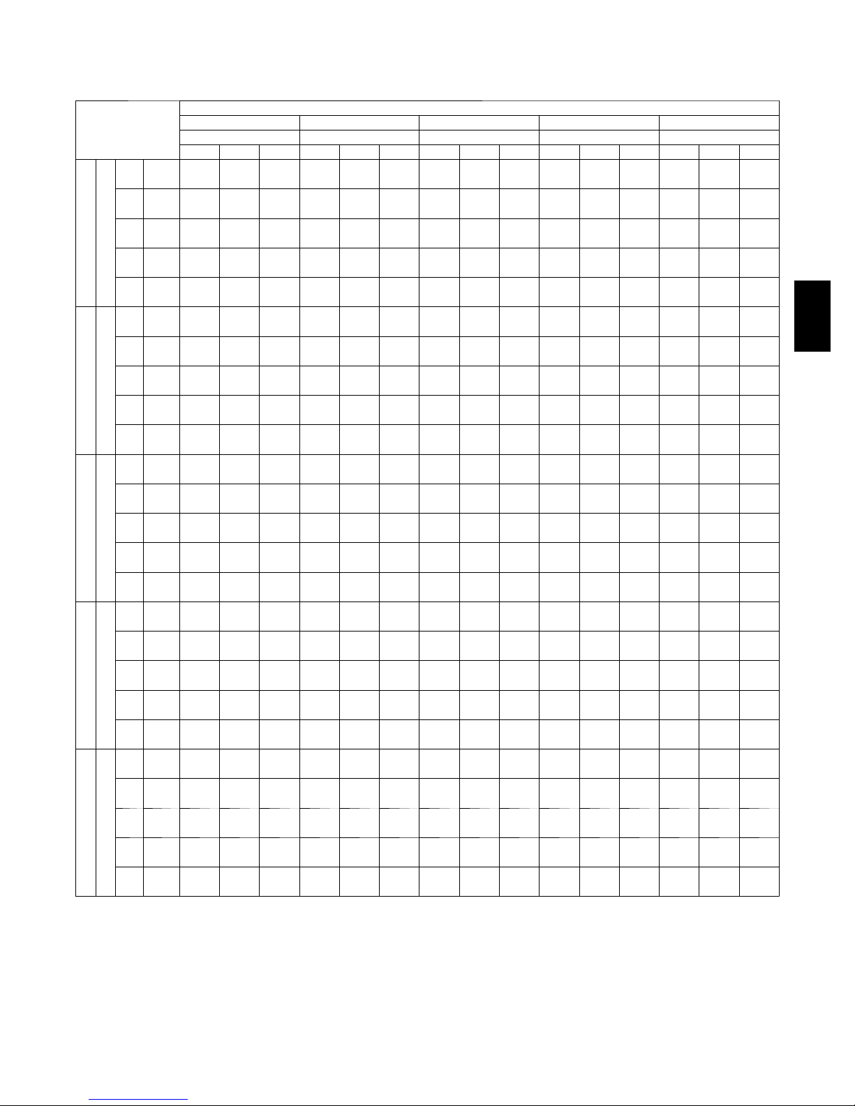
PERFORMANCE DATA (cont.)
569J*25A -- 524J*25 COMBINATION RATINGS
AMBIENT TEMPERATURE
85 95 105 115 125
EA (db) EA (db) EA (db) EA (db) EA (db)
75 80 85 75 80 85 75 80 85 75 80 85 75 80 85
THC 221.5 221.5 248.3 213.5 213.5 239.8 204.9 204.9 230.0 195.3 195.3 219.4 184.5 184.5 207.4
58
SHC 194.2 221.2 248.3 187.3 213.5 239.8 179.7 204.9 230.0 171.2 195.3 219.4 161.7 184.5 207.4
THC 232.4 232.4 232.9 222.4 222.4 228.1 211.4 211.4 222.6 199.4 199.4 216.7 186.5 186.5 209.6
62
SHC 173.9 203.4 232.9 169.1 198.6 228.1 163.7 193.2 222.6 157.9 187.3 216.7 151.3 180.5 209.6
THC 251.7 251.7 251.7 240.8 240.8 240.8 228.9 228.9 228.9 215.9 215.9 215.9 201.6 201.6 201.6
67
SHC 141.6 170.7 199.8 136.8 166.0 195.3 131.7 161.1 190.4 126.2 155.6 185.0 120.3 149.7 179.2
EA (wb)
6000 Cfm
7000 Cfm
8000 Cfm
9000 Cfm
10,000 Cfm
--- Not operational
THC --- T otal Cooling Capacity, Gross (1,000 Btuh)
SHC --- Sensible Cooling Capacity, Gross (1,000 Btuh)
THC 272.8 272.8 272.8 260.8 260.8 260.8 247.6 247.6 247.6 233.4 233.4 233.4 217.8 217.8 217.8
72
SHC 110.4 138.3 166.1 105.5 133.8 162.0 100.3 128.9 157.5 94.8 123.6 152.4 88.9 117.9 147.0
THC --- 290.9 290.9 --- 278.1 278.1 --- 263.7 263.7 --- 248.5 248.5 --- 231.6 231.6
76
SHC --- 111.5 144.5 --- 106.8 139.8 --- 103.0 136.0 --- 98.3 123.1 --- 92.9 120.2
THC 232.1 232.1 260.6 223.5 223.5 251.1 214.2 214.2 240.7 203.9 203.9 229.2 192.4 192.4 216.4
58
SHC 203.5 232.1 260.6 195.9 223.5 251.1 187.7 214.2 240.7 178.6 203.9 229.2 168.5 192.4 216.4
THC 238.9 238.9 253.7 228.3 228.3 248.2 217.1 217.1 242.1 205.0 205.0 234.5 192.8 192.8 222.1
62
SHC 186.0 219.8 253.7 180.8 214.5 248.2 175.1 208.6 242.1 168.4 201.5 234.5 159.1 190.6 222.1
THC 258.3 258.3 258.3 246.8 246.8 246.8 234.4 234.4 234.4 220.8 220.8 220.8 205.9 205.9 205.9
67
SHC 149.2 182.8 216.5 144.4 178.1 211.8 139.2 173.0 206.7 133.6 167.4 201.2 127.5 161.4 195.3
EA (wb)
THC 279.3 279.3 279.3 266.7 266.7 266.7 253.0 253.0 253.0 238.3 238.3 238.3 222.0 222.0 222.0
72
SHC 113.2 145.9 178.5 108.3 141.2 174.1 103.1 136.3 169.4 97.6 130.9 164.2 91.5 125.1 158.6
THC --- 297.5 297.5 --- 283.8 283.8 --- 269.2 269.2 --- 253.2 253.2 --- 235.5 235.5
76
SHC --- 116.1 154.6 --- 112.0 138.2 --- 107.4 137.4 --- 102.4 133.9 --- 96.7 129.1
THC 240.8 240.8 270.6 231.8 231.8 260.5 221.8 221.8 249.4 210.9 210.9 237.2 198.8 198.8 223.6
58
SHC 211.0 240.8 270.6 203.0 231.8 260.5 194.2 221.8 249.4 184.6 210.9 237.2 173.9 198.8 223.6
THC 244.2 244.2 271.9 233.5 233.5 265.4 222.6 222.6 255.7 211.0 211.0 245.3 198.8 198.8 232.0
62
SHC 196.6 234.3 271.9 190.9 228.2 265.4 183.3 219.5 255.7 175.2 210.2 245.3 165.5 198.8 232.0
THC 263.5 263.5 263.5 251.6 251.6 251.6 238.7 238.7 238.7 224.6 224.6 224.6 209.2 209.2 210.8
67
SHC 156.4 194.4 232.4 151.5 189.6 227.6 146.3 184.4 222.4 140.6 178.7 216.9 134.5 172.6 210.8
EA (wb)
THC 284.4 284.4 284.4 271.3 271.3 271.3 257.3 257.3 257.3 242.0 242.0 242.0 225.4 225.4 225.4
72
SHC 115.9 153.0 190.2 110.9 148.3 185.7 105.8 143.3 180.9 100.2 137.9 175.6 94.2 132.0 169.9
THC --- 302.5 302.5 --- 288.4 288.4 --- 273.4 273.4 --- 256.8 256.8 --- --- ---
76
SHC --- 120.4 153.1 --- 116.0 150.4 --- 111.3 146.9 --- 106.0 142.5 --- --- --THC 248.2 248.2 279.1 238.7 238.7 268.5 228.3 228.3 256.8 216.8 216.8 244.0 204.1 204.1 229.7
58
SHC 217.4 248.2 279.1 209.0 238.7 268.5 199.8 228.3 256.8 189.7 216.8 244.0 178.5 204.1 229.7
THC 249.3 249.3 285.8 238.9 238.9 277.7 228.3 228.3 266.5 216.8 216.8 253.2 204.1 204.1 238.4
62
SHC 204.9 245.4 285.8 198.4 238.0 277.7 190.1 228.3 266.5 180.4 216.8 253.2 169.8 204.1 238.4
THC 267.7 267.7 267.7 255.5 255.5 255.5 242.2 242.2 242.2 227.7 227.7 232.0 212.0 212.0 225.6
67
SHC 163.4 205.6 247.7 158.4 200.6 242.9 153.1 195.3 237.6 147.3 189.7 232.0 141.1 183.4 225.6
EA (wb)
THC 288.5 288.5 288.5 275.2 275.2 275.2 260.8 260.8 260.8 245.1 245.1 245.1 228.1 228.1 228.1
72
SHC 118.4 159.9 201.4 113.5 155.2 196.8 108.3 150.1 191.9 102.7 144.6 186.5 96.6 138.7 180.7
THC --- 306.6 306.6 --- 292.3 292.3 --- 276.7 276.7 --- --- --- --- --- ---
76
SHC --- 124.2 162.9 --- 119.7 159.4 --- 114.8 155.2 --- --- --- --- --- --THC 254.7 254.7 286.5 244.7 244.7 275.3 233.9 233.9 263.2 221.9 221.9 249.8 208.7 208.7 234.9
58
SHC 222.9 254.7 286.5 214.1 244.7 275.3 204.6 233.9 263.2 194.0 221.9 249.8 182.5 208.7 234.9
THC 254.6 254.6 297.3 244.8 244.8 285.3 233.9 233.9 273.1 221.9 221.9 259.2 208.6 208.6 243.8
62
SHC 212.0 254.6 297.3 203.4 244.4 285.3 194.6 233.9 273.1 184.5 221.9 259.2 173.4 208.6 243.8
THC 271.3 271.3 271.3 258.7 258.7 258.7 245.1 245.1 252.3 230.3 230.3 246.7 214.0 214.0 239.7
67
SHC 170.0 216.4 262.7 165.0 211.4 257.7 159.6 206.0 252.3 153.9 200.3 246.7 147.3 193.5 239.7
EA (wb)
THC 292.0 292.0 292.0 278.4 278.4 278.4 263.7 263.7 263.7 247.4 247.4 247.4 230.0 230.0 230.0
72
SHC 120.9 166.6 212.3 116.0 161.8 207.6 110.7 156.7 202.6 105.0 151.0 197.1 98.9 145.1 191.2
THC --- 310.1 310.1 --- 295.3 295.3 --- --- --- --- --- --- --- --- ---
76
SHC --- 127.8 171.4 --- 123.2 167.5 --- --- --- --- --- --- --- --- ---
569J
39
Page 40

PERFORMANCE DATA (cont.)
569J*25A-- 524J*28 COMBINATION RATINGS
AMBIENT TEMPERATURE
85 95 105 115 125
EA (db) EA (db) EA (db) EA (db) EA (db)
75 80 85 75 80 85 75 80 85 75 80 85 75 80 85
THC 236.2 236.2 266.2 228.0 228.0 256.9 219.0 219.0 246.7 209.0 209.0 235.5 198.1 198.1 223.2
58
SHC 206.3 236.2 266.2 199.0 228.0 256.9 191.2 219.0 246.7 182.5 209.0 235.5 172.9 198.1 223.2
THC 241.6 241.6 264.9 231.6 231.6 259.3 220.9 220.9 252.9 209.4 209.4 244.9 198.2 198.2 231.8
62
SHC 191.3 228.1 264.9 186.2 222.8 259.3 180.6 216.7 252.9 173.9 209.4 244.9 164.7 198.2 231.8
THC 262.3 262.3 262.3 251.0 251.0 251.0 238.9 238.9 238.9 225.7 225.7 225.7 211.4 211.4 211.4
67
EA (wb)
7500 Cfm
569J
EA (wb)
8750 Cfm
EA (wb)
10,000 Cfm
EA (wb)
11,250 Cfm
EA (wb)
12,500 Cfm
--- Not operational
THC --- T otal Cooling Capacity, Gross (1,000 Btuh)
SHC --- Sensible Cooling Capacity, Gross (1,000 Btuh)
SHC 154.6 192.0 229.4 149.9 187.3 224.6 145.0 182.3 219.6 139.6 176.9 214.2 133.9 171.1 208.4
THC 284.6 284.6 284.6 272.4 272.4 272.4 259.2 259.2 259.2 244.7 244.7 244.7 229.2 229.2 229.2
72
SHC 116.2 153.9 191.6 111.6 149.3 186.9 106.8 144.3 181.9 101.5 139.0 176.4 95.9 133.3 170.7
THC --- 303.1 303.1 --- 289.9 289.9 --- 275.8 275.8 --- 260.4 260.4 --- --- ---
76
SHC --- 123.4 162.7 --- 118.8 157.9 --- 114.0 152.8 --- 108.7 147.3 --- --- --THC 247.1 247.1 278.5 238.2 238.2 268.4 228.5 228.5 257.5 217.8 217.8 245.4 206.1 206.1 232.2
58
SHC 215.7 247.1 278.5 208.0 238.2 268.4 199.5 228.5 257.5 190.2 217.8 245.4 179.9 206.1 232.2
THC 248.7 248.7 286.9 238.6 238.6 279.1 228.7 228.7 267.4 218.0 218.0 254.9 206.2 206.2 241.2
62
SHC 204.5 245.7 286.9 198.2 238.6 279.1 189.9 228.7 267.4 181.1 218.0 254.9 171.3 206.2 241.2
THC 268.2 268.2 268.2 256.5 256.5 256.5 243.9 243.9 243.9 230.1 230.1 234.0 215.3 215.3 227.8
67
SHC 164.0 206.9 249.7 159.3 202.1 244.9 154.2 197.0 239.7 148.7 191.4 234.0 142.8 185.3 227.8
THC 290.8 290.8 290.8 277.9 277.9 277.9 264.2 264.2 264.2 249.2 249.2 249.2 233.1 233.1 233.1
72
SHC 120.1 163.2 206.3 115.4 158.5 201.5 110.5 153.4 196.4 105.1 148.0 190.9 99.4 142.2 184.9
THC --- 309.2 309.2 --- 295.5 295.5 --- 280.8 280.8 --- --- --- --- --- ---
76
SHC --- 128.3 172.8 --- 123.7 168.0 --- 118.7 162.8 --- --- --- --- --- --THC 255.9 255.9 288.4 246.5 246.5 277.8 236.2 236.2 266.1 224.9 224.9 253.4 212.5 212.5 239.4
58
SHC 223.5 255.9 288.4 215.2 246.5 277.8 206.2 236.2 266.1 196.3 224.9 253.4 185.5 212.5 239.4
THC 256.1 256.1 299.5 246.7 246.7 288.4 236.3 236.3 276.4 225.0 225.0 263.1 212.6 212.6 248.6
62
SHC 212.7 256.1 299.5 204.9 246.7 288.4 196.3 236.3 276.4 186.9 225.0 263.1 176.6 212.6 248.6
THC 272.9 272.9 272.9 260.7 260.7 264.2 247.7 247.7 258.7 233.6 233.6 252.6 218.5 218.5 245.9
67
SHC 173.0 221.1 269.2 168.1 216.1 264.2 162.9 210.8 258.7 157.2 204.9 252.6 151.1 198.5 245.9
THC 295.5 295.5 295.5 282.2 282.2 282.2 268.1 268.1 268.1 252.7 252.7 252.7 236.1 236.1 236.1
72
SHC 123.7 172.1 220.4 119.0 167.3 215.5 114.0 162.2 210.3 108.6 156.6 204.7 102.8 150.7 198.6
THC --- 314.0 314.0 --- 299.8 299.8 --- --- --- --- --- --- --- --- ---
76
SHC --- 133.0 182.6 --- 128.2 177.7 --- --- --- --- --- --- --- --- --THC 263.3 263.3 296.8 253.4 253.4 285.5 242.6 242.6 273.4 230.7 230.7 260.0 217.7 217.7 245.4
58
SHC 229.9 263.3 296.8 221.2 253.4 285.5 211.8 242.6 273.4 201.5 230.7 260.0 190.1 217.7 245.4
THC 263.5 263.5 308.1 253.6 253.6 296.5 242.8 242.8 283.9 230.9 230.9 270.0 217.9 217.9 254.8
62
SHC 218.9 263.5 308.1 210.6 253.6 296.5 201.7 242.8 283.9 191.8 230.9 270.0 181.0 217.9 254.8
THC 276.6 276.6 287.7 264.2 264.2 282.3 250.9 250.9 276.5 236.5 236.5 269.8 221.3 221.3 262.1
67
SHC 181.4 234.6 287.7 176.4 229.4 282.3 171.1 223.8 276.5 165.2 217.5 269.8 158.6 210.3 262.1
THC 299.3 299.3 299.3 285.7 285.7 285.7 271.2 271.2 271.2 255.4 255.4 255.4 238.5 238.5 238.5
72
SHC 127.2 180.6 234.1 122.4 175.7 229.1 117.3 170.6 223.8 111.9 165.0 218.0 106.1 159.0 211.9
THC --- --- --- --- --- --- --- --- --- --- --- --- --- --- ---
76
SHC --- --- --- --- --- --- --- --- --- --- --- --- --- --- --THC 269.7 269.7 303.9 259.3 259.3 292.2 248.1 248.1 279.5 235.7 235.7 265.6 222.2 222.2 250.4
58
SHC 235.5 269.7 303.9 226.4 259.3 292.2 216.6 248.1 279.5 205.8 235.7 265.6 194.1 222.2 250.4
THC 269.8 269.8 315.5 259.4 259.4 303.4 248.2 248.2 290.2 235.8 235.8 275.7 222.4 222.4 260.0
62
SHC 224.2 269.8 315.5 215.5 259.4 303.4 206.2 248.2 290.2 195.9 235.8 275.7 184.7 222.4 260.0
THC 279.8 279.8 305.1 267.1 267.1 299.3 253.7 253.7 292.8 239.2 239.2 285.1 223.8 223.8 275.5
67
SHC 189.4 247.2 305.1 184.3 241.8 299.3 178.6 235.7 292.8 172.3 228.7 285.1 164.9 220.2 275.5
THC 302.4 302.4 302.4 288.5 288.5 288.5 273.7 273.7 273.7 257.7 257.7 257.7 240.4 240.4 240.4
72
SHC 130.5 188.9 247.3 125.7 184.0 242.3 120.6 178.7 236.9 115.1 173.1 231.0 109.2 167.0 224.7
THC --- --- --- --- --- --- --- --- --- --- --- --- --- --- ---
76
SHC --- --- --- --- --- --- --- --- --- --- --- --- --- --- ---
40
Page 41

PERFORMANCE DATA (cont.)
569J*25D-- 524J*25 COMBINATION RATINGS
AMBIENT TEMPERATURE
85 95 105 115 125
EA (db) EA (db) EA (db) EA (db) EA (db)
75 80 85 75 80 85 75 80 85 75 80 85 75 80 85
THC 220.0 220.0 247.0 212.1 212.1 238.2 203.4 203.4 228.5 193.7 193.7 217.7 182.8 182.8 205.5
58
SHC 193.0 220.0 247.0 186.0 212.1 238.2 178.3 203.4 228.5 169.8 193.7 217.7 160.1 182.8 205.5
THC 230.1 230.1 234.9 220.0 220.0 230.0 209.0 209.0 224.6 197.0 197.0 218.3 183.9 183.9 210.5
62
SHC 174.4 204.7 234.9 169.6 199.8 230.0 164.2 194.4 224.6 158.2 188.3 218.3 151.2 180.8 210.5
THC 251.0 251.0 251.0 239.9 239.9 239.9 227.9 227.9 227.9 214.6 214.6 214.6 199.9 199.9 199.9
67
SHC 142.4 172.3 202.2 137.6 167.6 197.6 132.5 162.6 192.7 126.9 157.1 187.3 120.9 151.1 181.3
EA (wb)
6000 Cfm
7000 Cfm
8000 Cfm
9000 Cfm
10,000 Cfm
--- Not operational
THC --- T otal Cooling Capacity, Gross (1,000 Btuh)
SHC --- Sensible Cooling Capacity, Gross (1,000 Btuh)
THC 274.2 274.2 274.2 262.0 262.0 262.0 248.7 248.7 248.7 234.1 234.1 234.1 217.9 217.9 217.9
72
SHC 111.3 140.1 168.9 106.4 135.5 164.6 101.2 130.6 160.0 95.6 125.2 154.8 89.5 119.3 149.1
THC --- 294.4 294.4 --- 281.0 281.0 --- 266.4 266.4 --- 250.7 250.7 --- 233.4 233.4
76
SHC --- 113.0 146.0 --- 108.7 141.7 --- 104.6 133.3 --- 99.7 126.2 --- 94.1 122.4
THC 230.8 230.8 259.3 222.2 222.2 249.7 212.8 212.8 239.2 202.3 202.3 227.5 190.6 190.6 214.4
58
SHC 202.3 230.8 259.3 194.7 222.2 249.7 186.4 212.8 239.2 177.2 202.3 227.5 166.9 190.6 214.4
THC 236.4 236.4 255.9 225.9 225.9 250.3 215.3 215.3 241.3 203.8 203.8 231.2 191.3 191.3 220.8
62
SHC 186.6 221.3 255.9 181.4 215.8 250.3 174.2 207.7 241.3 166.3 198.7 231.2 158.0 189.4 220.8
THC 257.6 257.6 257.6 245.9 245.9 245.9 233.2 233.2 233.2 219.3 219.3 219.3 204.0 204.0 204.0
67
SHC 150.4 185.0 219.6 145.5 180.2 214.9 140.3 175.0 209.8 134.6 169.4 204.2 128.4 163.2 198.1
EA (wb)
THC 281.0 281.0 281.0 268.1 268.1 268.1 254.2 254.2 254.2 238.8 238.8 238.8 222.0 222.0 222.0
72
SHC 114.4 148.1 181.8 109.5 143.4 177.3 104.2 138.4 172.5 98.5 132.8 167.2 92.3 126.8 161.3
THC --- 301.1 301.1 --- 287.2 287.2 --- 272.2 272.2 --- 255.7 255.7 --- --- ---
76
SHC --- 118.2 151.3 --- 113.9 143.1 --- 109.2 140.7 --- 104.0 136.6 --- --- --THC 239.6 239.6 269.4 230.5 230.5 259.2 220.5 220.5 248.0 209.4 209.4 235.6 197.0 197.0 221.7
58
SHC 209.9 239.6 269.4 201.8 230.5 259.2 193.0 220.5 248.0 183.3 209.4 235.6 172.3 197.0 221.7
THC 241.9 241.9 274.0 232.2 232.2 263.9 222.0 222.0 253.2 210.1 210.1 242.3 197.0 197.0 230.1
62
SHC 197.3 235.6 274.0 189.6 226.8 263.9 181.7 217.5 253.2 173.3 207.8 242.3 163.9 197.0 230.1
THC 262.7 262.7 262.7 250.5 250.5 250.5 237.3 237.3 237.3 222.9 222.9 222.9 207.1 207.1 214.0
67
SHC 158.0 197.1 236.3 153.0 192.2 231.4 147.6 186.9 226.1 141.8 181.1 220.3 135.5 174.7 214.0
EA (wb)
THC 286.3 286.3 286.3 272.8 272.8 272.8 258.4 258.4 258.4 242.5 242.5 242.5 225.1 225.1 225.1
72
SHC 117.4 155.7 194.1 112.4 150.9 189.5 107.1 145.8 184.5 101.3 140.1 179.0 95.1 134.0 173.0
THC --- 306.6 306.6 --- 292.0 292.0 --- 276.5 276.5 --- --- --- --- --- ---
76
SHC --- 122.8 157.5 --- 118.2 154.2 --- 113.3 150.2 --- --- --- --- --- --THC 247.2 247.2 278.0 237.6 237.6 267.3 227.1 227.1 255.5 215.4 215.4 242.4 202.4 202.4 227.8
58
SHC 216.4 247.2 278.0 207.9 237.6 267.3 198.7 227.1 255.5 188.4 215.4 242.4 176.9 202.4 227.8
THC 249.4 249.4 281.3 239.3 239.3 272.2 227.9 227.9 262.4 215.4 215.4 251.6 202.3 202.3 236.4
62
SHC 202.5 241.9 281.3 195.4 233.8 272.2 187.7 225.1 262.4 179.2 215.4 251.6 168.3 202.3 236.4
THC 266.8 266.8 266.8 254.2 254.2 254.2 240.6 240.6 241.9 225.9 225.9 235.9 209.5 209.5 229.3
67
SHC 165.2 208.8 252.4 160.1 203.8 247.4 154.7 198.3 241.9 148.7 192.3 235.9 142.2 185.7 229.3
EA (wb)
THC 290.4 290.4 290.4 276.6 276.6 276.6 261.8 261.8 261.8 245.4 245.4 245.4 227.6 227.6 227.6
72
SHC 120.1 163.0 205.9 115.1 158.2 201.2 109.8 152.9 196.1 103.9 147.2 190.5 97.6 141.0 184.4
THC --- 310.7 310.7 --- 295.9 295.9 --- --- --- --- --- --- --- --- ---
76
SHC --- 126.7 167.1 --- 122.1 163.2 --- --- --- --- --- --- --- --- --THC 253.7 253.7 285.4 243.7 243.7 274.2 232.7 232.7 261.9 220.5 220.5 248.2 206.9 206.9 233.0
58
SHC 221.9 253.7 285.4 213.1 243.7 274.2 203.5 232.7 261.9 192.7 220.5 248.2 180.8 206.9 233.0
THC 255.5 255.5 290.4 244.0 244.0 282.1 232.6 232.6 271.8 220.5 220.5 257.6 206.9 206.9 241.9
62
SHC 208.4 249.4 290.4 201.5 241.8 282.1 193.5 232.6 271.8 183.3 220.5 257.6 171.9 206.9 241.9
THC 270.1 270.1 270.1 257.2 257.2 262.7 243.3 243.3 257.0 228.0 228.0 250.8 211.4 211.4 243.3
67
SHC 172.1 220.0 267.8 166.9 214.8 262.7 161.4 209.2 257.0 155.2 203.0 250.8 148.3 195.8 243.3
EA (wb)
THC 293.9 293.9 293.9 279.7 279.7 279.7 264.4 264.4 264.4 247.8 247.8 247.8 229.6 229.6 229.6
72
SHC 122.8 170.1 217.4 117.7 165.1 212.5 112.3 159.8 207.3 106.4 154.0 201.6 100.1 147.8 195.4
THC --- 314.3 314.3 --- 299.1 299.1 --- --- --- --- --- --- --- --- ---
76
SHC --- 130.6 175.9 --- 125.8 171.7 --- --- --- --- --- --- --- --- ---
569J
41
Page 42

PERFORMANCE DATA (cont.)
569J*25D-- 524J*28 COMBINATION RATINGS
AMBIENT TEMPERATURE
85 95 105 115 125
EA (db) EA (db) EA (db) EA (db) EA (db)
75 80 85 75 80 85 75 80 85 75 80 85 75 80 85
THC 237.5 237.5 261.6 228.5 228.5 251.7 218.7 218.7 240.9 207.7 207.7 228.8 195.9 195.9 215.8
58
SHC 213.4 237.5 261.6 205.3 228.5 251.7 196.5 218.7 240.9 186.6 207.7 228.8 176.0 195.9 215.8
THC 241.6 241.6 261.6 230.8 230.8 255.7 220.1 220.1 246.2 207.9 207.9 236.1 196.1 196.1 222.6
62
SHC 201.2 231.4 261.6 195.7 225.7 255.7 188.0 217.1 246.2 179.8 207.9 236.1 169.5 196.1 222.6
THC 262.2 262.2 262.2 250.1 250.1 250.1 237.0 237.0 237.0 222.5 222.5 222.5 207.4 207.4 207.4
67
EA (wb)
7500 Cfm
569J
EA (wb)
8750 Cfm
EA (wb)
10,000 Cfm
EA (wb)
11,250 Cfm
EA (wb)
12,500 Cfm
--- Not operational
THC --- T otal Cooling Capacity, Gross (1,000 Btuh)
SHC --- Sensible Cooling Capacity, Gross (1,000 Btuh)
SHC 163.9 194.6 225.3 158.9 189.6 220.3 153.6 184.2 214.9 147.7 178.3 208.9 141.6 172.2 202.7
THC 285.5 285.5 285.5 272.2 272.2 272.2 257.9 257.9 257.9 242.1 242.1 242.1 225.6 225.6 225.6
72
SHC 125.1 156.0 186.9 120.2 151.0 181.9 114.9 145.7 176.5 109.2 139.9 170.6 103.2 133.8 164.5
THC --- 305.5 305.5 --- 291.1 291.1 --- --- --- --- --- --- --- --- ---
76
SHC --- 124.9 156.9 --- 120.0 151.8 --- --- --- --- --- --- --- --- --THC 248.0 248.0 273.2 238.3 238.3 262.5 227.7 227.7 250.8 215.9 215.9 237.8 203.3 203.3 223.9
58
SHC 222.8 248.0 273.2 214.1 238.3 262.5 204.6 227.7 250.8 194.0 215.9 237.8 182.6 203.3 223.9
THC 249.2 249.2 280.0 238.6 238.6 270.9 227.9 227.9 258.8 216.1 216.1 245.4 203.4 203.4 231.0
62
SHC 213.6 246.8 280.0 206.3 238.6 270.9 197.0 227.9 258.8 186.8 216.1 245.4 175.8 203.4 231.0
THC 267.7 267.7 267.7 254.9 254.9 254.9 241.2 241.2 241.2 226.3 226.3 228.3 210.6 210.6 221.6
67
SHC 174.8 210.1 245.4 169.7 204.9 240.2 164.2 199.3 234.5 158.2 193.2 228.3 151.8 186.7 221.6
THC 291.3 291.3 291.3 277.3 277.3 277.3 262.4 262.4 262.4 246.1 246.1 246.1 228.9 228.9 228.9
72
SHC 130.3 165.7 201.2 125.2 160.6 196.0 119.9 155.2 190.5 114.0 149.2 184.4 108.0 143.1 178.1
THC --- 311.4 311.4 --- --- --- --- --- --- --- --- --- --- --- ---
76
SHC --- 130.1 166.5 --- --- --- --- --- --- --- --- --- --- --- --THC 256.5 256.5 282.5 246.1 246.1 271.1 234.9 234.9 258.8 222.4 222.4 245.0 209.1 209.1 230.4
58
SHC 230.4 256.5 282.5 221.2 246.1 271.1 211.1 234.9 258.8 199.9 222.4 245.0 187.9 209.1 230.4
THC 256.7 256.7 291.5 246.3 246.3 279.7 235.1 235.1 267.0 222.6 222.6 252.8 209.3 209.3 237.6
62
SHC 221.9 256.7 291.5 213.0 246.3 279.7 203.2 235.1 267.0 192.4 222.6 252.8 180.9 209.3 237.6
THC 271.7 271.7 271.7 258.6 258.6 259.0 244.6 244.6 253.0 229.2 229.2 246.3 213.3 213.3 238.9
67
SHC 185.1 224.9 264.6 179.8 219.4 259.0 174.1 213.6 253.0 167.8 207.1 246.3 161.1 200.0 238.9
THC 295.6 295.6 295.6 281.2 281.2 281.2 265.8 265.8 265.8 249.0 249.0 249.0 --- --- ---
72
SHC 135.2 175.0 214.9 130.0 169.8 209.6 124.6 164.2 203.9 118.6 158.2 197.7 --- --- --THC --- --- --- --- --- --- --- --- --- --- --- --- --- --- ---
76
SHC --- --- --- --- --- --- --- --- --- --- --- --- --- --- --THC 263.5 263.5 290.3 252.7 252.7 278.3 240.9 240.9 265.3 227.9 227.9 251.0 214.0 214.0 235.7
58
SHC 236.8 263.5 290.3 227.0 252.7 278.3 216.4 240.9 265.3 204.7 227.9 251.0 192.2 214.0 235.7
THC 263.7 263.7 299.5 252.9 252.9 287.1 241.1 241.1 273.7 228.0 228.0 258.9 214.1 214.1 243.1
62
SHC 228.0 263.7 299.5 218.6 252.9 287.1 208.4 241.1 273.7 197.1 228.0 258.9 185.1 214.1 243.1
THC 275.0 275.0 282.7 261.6 261.6 276.8 247.2 247.2 270.3 231.8 231.8 262.6 216.0 216.0 251.8
67
SHC 194.9 238.8 282.7 189.4 233.1 276.8 183.4 226.8 270.3 176.6 219.6 262.6 168.2 210.0 251.8
THC 299.0 299.0 299.0 284.2 284.2 284.2 268.4 268.4 268.4 251.3 251.3 251.3 --- --- ---
72
SHC 139.8 184.0 228.1 134.6 178.7 222.7 129.0 173.0 216.9 123.1 166.8 210.6 --- --- --THC --- --- --- --- --- --- --- --- --- --- --- --- --- --- ---
76
SHC --- --- --- --- --- --- --- --- --- --- --- --- --- --- --THC 269.5 269.5 296.9 258.2 258.2 284.4 245.9 245.9 270.9 232.4 232.4 256.0 218.0 218.0 240.1
58
SHC 242.2 269.5 296.9 232.0 258.2 284.4 221.0 245.9 270.9 208.8 232.4 256.0 195.9 218.0 240.1
THC 269.7 269.7 306.3 258.4 258.4 293.4 246.1 246.1 279.4 232.5 232.5 264.0 218.1 218.1 247.6
62
SHC 233.2 269.7 306.3 223.4 258.4 293.4 212.8 246.1 279.4 201.0 232.5 264.0 188.6 218.1 247.6
THC 277.8 277.8 299.7 264.1 264.1 293.2 249.7 249.7 285.6 234.5 234.5 274.3 218.8 218.8 261.2
67
SHC 204.0 251.8 299.7 198.2 245.7 293.2 191.6 238.6 285.6 183.1 228.7 274.3 173.4 217.3 261.2
THC 301.7 301.7 301.7 286.6 286.6 286.6 270.5 270.5 270.5 --- --- --- --- --- ---
72
SHC 144.3 192.6 241.0 139.0 187.2 235.5 133.4 181.5 229.6 --- --- --- --- --- --THC --- --- --- --- --- --- --- --- --- --- --- --- --- --- ---
76
SHC --- --- --- --- --- --- --- --- --- --- --- --- --- --- ---
42
Page 43

ELECTRICAL DATA
569J*07A COOLING WITHOUT POWERED CONVENIENCE OUTLET
V --- P h --- H z
208/230--- 3--- 60 187 253 19 123 325 1.5 26.8 45
4 6 0 --- 3 --- 6 0 414 506 9.7 62 325 0.8 13.7 20
5 7 5 --- 3 --- 6 0 518 633 7.4 50 325 0.7 10.7 15
VOLTAGE RANGE COMP 1 OFM (ea) POWER SUPPLY
MIN MAX RLA LRA WATTS FLA MCA Fuse
569J*07A COOLING WITH POWERED CONVENIENCE OUTLET
V --- P h --- H z
208/230--- 3--- 60 187 253 19 123 325 1.5 31.6 50
4 6 0 --- 3 --- 6 0 414 506 9.7 62 325 0.8 15.9 25
5 7 5 --- 3 --- 6 0 518 633 7.4 50 325 0.7 12.4 15
VOLTAGE RANGE COMP 1 OFM (ea) POWER SUPPLY
MIN MAX RLA LRA WATTS FLA MCA Fuse
569J*08A COOLING WITHOUT POWERED CONVENIENCE OUTLET
V --- P h --- H z
208/230--- 3--- 60 187 253 25 164 325 1.5 34.3 50
4 6 0 --- 3 --- 6 0 414 506 12.2 100 325 0.8 16.9 25
5 7 5 --- 3 --- 6 0 518 633 9.0 78 325 0.7 12.7 20
VOLTAGE RANGE COMP 1 OFM (ea) POWER SUPPLY
MIN MAX RLA LRA WATTS FLA MCA Fuse
569J*08A COOLING WITH POWERED CONVENIENCE OUTLET
569J
V --- P h --- H z
208/230--- 3--- 60 187 253 25 164 325 1.5 39.1 60
4 6 0 --- 3 --- 6 0 414 506 12.2 100 325 0.8 19.1 30
5 7 5 --- 3 --- 6 0 518 633 9.0 78 325 0.7 14.4 20
VOLTAGE RANGE COMP 1 OFM (ea) POWER SUPPLY
MIN MAX RLA LRA WATTS FLA MCA Fuse
43
Page 44
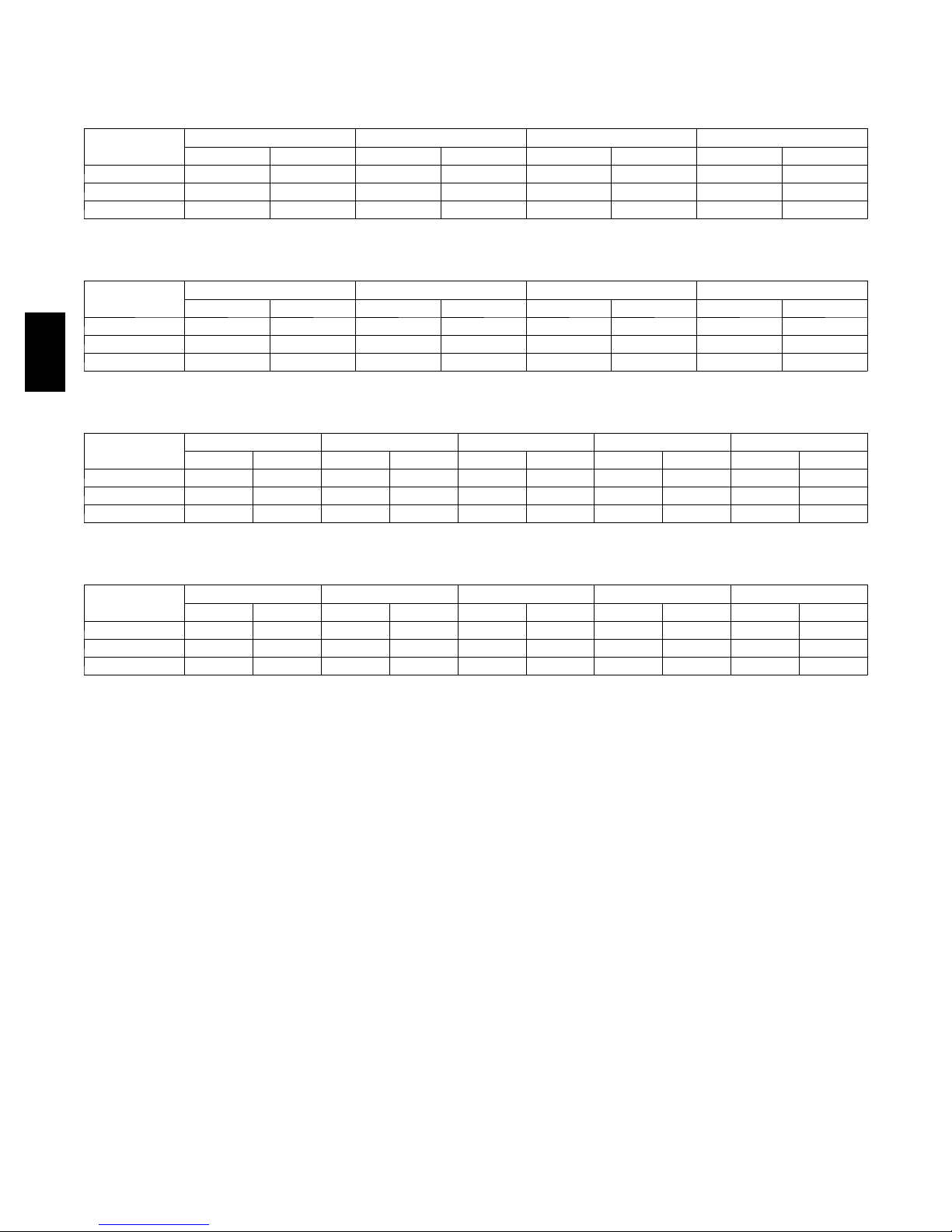
ELECTRICAL DATA (cont.)
569J*12A COOLING WITHOUT POWERED CONVENIENCE OUTLET
V --- P h --- H z
208/230--- 3--- 60 187 253 30.1 225 325 1.5 40.6 60
4 6 0 --- 3 --- 6 0 414 506 16.7 114 325 0.8 22.5 30
5 7 5 --- 3 --- 6 0 518 633 12.2 80 325 0.7 16.7 25
VOLTAGE RANGE COMP 1 OFM (ea) POWER SUPPLY
MIN MAX RLA LRA WATTS FLA MCA Fuse
569J*12A COOLING WITH POWERED CONVENIENCE OUTLET
V --- P h --- H z
208/230--- 3--- 60 187 253 30.1 225 325 1.5 45.4 60
4 6 0 --- 3 --- 6 0 414 506 16.7 114 325 0.8 24.7 30
569J
5 7 5 --- 3 --- 6 0 518 633 12.2 80 325 0.7 18.4 30
VOLTAGE RANGE COMP 1 OFM (ea) POWER SUPPLY
MIN MAX RLA LRA WATTS FLA MCA Fuse
569J*12D COOLING WITHOUT POWERED CONVENIENCE OUTLET
V --- P h --- H z
208/230--- 3--- 60 187 253 15.9 110 15.9 110 325 1.5 38.8 50
4 6 0 --- 3 --- 6 0 414 506 7.7 52 7.7 52 325 0.8 18.9 25
5 7 5 --- 3 --- 6 0 518 633 5.7 39 5.7 39 325 0.7 14.2 20
VOLTAGE RANGE COMP 1 COMP 2 OFM (ea) POWER SUPPLY
MIN MAX RLA LRA RLA LRA WAT TS FLA MCA Fuse
569J*12D COOLING WITH POWERED CONVENIENCE OUTLET
V --- P h --- H z
208/230--- 3--- 60 187 253 15.9 110 15.9 110 325 1.5 43.6 50
4 6 0 --- 3 --- 6 0 414 506 7.7 52 7.7 52 325 0.8 21.1 25
5 7 5 --- 3 --- 6 0 518 633 5.7 39 5.7 39 325 0.7 15.9 20
VOLTAGE RANGE COMP 1 COMP 2 OFM (ea) POWER SUPPLY
MIN MAX RLA LRA RLA LRA WAT TS FLA MCA Fuse
44
Page 45
ELECTRICAL DATA (cont.)
569J*14A COOLING WITHOUT POWERED CONVENIENCE OUTLET
V --- P h --- H z
208/230--- 3--- 60 187 253 48.1 245 325 1.5 63.1 80
4 6 0 --- 3 --- 6 0 414 506 18.6 125 325 0.8 24.9 30
5 7 5 --- 3 --- 6 0 518 633 14.7 100 325 0.7 19.8 30
VOLTAGE RANGE COMP 1 OFM (ea) POWER SUPPLY
MIN MAX RLA LRA WATTS FLA MCA Fuse
569J*14A COOLING WITH POWERED CONVENIENCE OUTLET
V --- P h --- H z
208/230--- 3--- 60 187 253 48.1 245 325 1.5 67.9 80
4 6 0 --- 3 --- 6 0 414 506 18.6 125 325 0.8 27.1 45
5 7 5 --- 3 --- 6 0 518 633 14.7 100 325 0.7 21.5 30
VOLTAGE RANGE COMP 1 OFM (ea) POWER SUPPLY
MIN MAX RLA LRA WATTS FLA MCA Fuse
569J*14D COOLING WITHOUT POWERED CONVENIENCE OUTLET
V --- P h --- H z
208/230--- 3--- 60 187 253 22.40 149 22.40 149 325 1.5 53.4 60
4 6 0 --- 3 --- 6 0 414 506 10.6 75 10.6 75 325 0.8 25.5 30
5 7 5 --- 3 --- 6 0 518 633 7.7 54 7.7 54 325 0.7 18.7 25
VOLTAGE RANGE COMP 1 COMP 2 OFM (ea) POWER SUPPLY
MIN MAX RLA LRA RLA LRA WAT TS FLA MCA Fuse
569J*14D COOLING WITH POWERED CONVENIENCE OUTLET
569J
V --- P h --- H z
208/230--- 3--- 60 187 253 22.40 149 22.40 149 325 1.5 58.2 80
4 6 0 --- 3 --- 6 0 414 506 10.6 75 10.6 75 325 0.8 27.7 35
5 7 5 --- 3 --- 6 0 518 633 7.7 54 7.7 54 325 0.7 20.4 25
VOLTAGE RANGE COMP 1 COMP 2 OFM (ea) POWER SUPPLY
MIN MAX RLA LRA RLA LRA WAT TS FLA MCA Fuse
45
Page 46

ELECTRICAL DATA (cont.)
569J*16A COOLING WITHOUT POWERED CONVENIENCE OUTLET
V --- P h --- H z
208/230--- 3--- 60 187 253 25 164 25 164 325 1.5 60.8 80
4 6 0 --- 3 --- 6 0 414 506 12.2 100 12.2 100 325 0.8 29.9 40
5 7 5 --- 3 --- 6 0 518 633 9 78 9 78 325 0.7 22.4 30
VOLTAGE RANGE COMP 1 COMP 2 OFM (ea) POWER SUPPLY
MIN MAX RLA LRA RLA LRA WAT TS FLA MCA Fuse
569J*16A COOLING WITH POWERED CONVENIENCE OUTLET
V --- P h --- H z
208/230--- 3--- 60 187 253 25 164 25 164 325 1.5 66.6 90
4 6 0 --- 3 --- 6 0 414 506 12.2 100 12.2 100 325 0.8 32.1 40
569J
5 7 5 --- 3 --- 6 0 518 633 9 78 9 78 325 0.7 24.1 30
VOLTAGE RANGE COMP 1 COMP 2 OFM (ea) POWER SUPPLY
MIN MAX RLA LRA RLA LRA WAT TS FLA MCA Fuse
569J*16D COOLING WITHOUT POWERED CONVENIENCE OUTLET
V --- P h --- H z
208/230--- 3--- 60 187 253 25 164 25 164 325 1.5 60.7 80
4 6 0 --- 3 --- 6 0 414 506 12.2 100 12.2 100 325 0.8 29.8 40
5 7 5 --- 3 --- 6 0 518 633 9 78 9 78 325 0.6 22.0 30
VOLTAGE RANGE COMP 1 COMP 2 OFM (ea) POWER SUPPLY
MIN MAX RLA LRA RLA LRA WAT TS FLA MCA Fuse
569J*16D COOLING WITH POWERED CONVENIENCE OUTLET
V --- P h --- H z
208/230--- 3--- 60 187 253 25 164 25 164 325 1.5 65.6 90
4 6 0 --- 3 --- 6 0 414 506 12.2 100 12.2 100 325 0.8 32.1 40
5 7 5 --- 3 --- 6 0 518 633 9 78 9 78 325 0.7 24.1 30
VOLTAGE RANGE COMP 1 COMP 2 OFM (ea) POWER SUPPLY
MIN MAX RLA LRA RLA LRA WAT TS FLA MCA Fuse
46
Page 47
ELECTRICAL DATA (cont.)
569J*25A COOLING WITHOUT POWERED CONVENIENCE OUTLET
V --- P h --- H z
208/230--- 3--- 60 187 253 30.1 225 30.1 225 325 1.5 73.7 100
4 6 0 --- 3 --- 6 0 414 506 16.7 114 16.7 114 325 0.8 40.8 50
5 7 5 --- 3 --- 6 0 518 633 12.2 80 12.2 80 325 0.7 30.3 40
VOLTAGE RANGE COMP 1 COMP 2 OFM (ea) POWER SUPPLY
MIN MAX RLA LRA RLA LRA WAT TS FLA MCA Fuse
569J*25A COOLING WITH POWERED CONVENIENCE OUTLET
V --- P h --- H z
208/230--- 3--- 60 187 253 30.1 225 30.1 225 325 1.5 78.5 100
4 6 0 --- 3 --- 6 0 414 506 16.7 114 16.7 114 325 0.8 43.0 50
5 7 5 --- 3 --- 6 0 518 633 12.2 80 12.2 80 325 0.7 32.0 40
VOLTAGE RANGE COMP 1 COMP 2 OFM (ea) POWER SUPPLY
MIN MAX RLA LRA RLA LRA WAT TS FLA MCA Fuse
569J*25D COOLING WITHOUT POWERED CONVENIENCE OUTLET
V --- P h --- H z
208/230--- 3--- 60 187 253 30.1 225 30.1 225 325 1.5 73.7 100
4 6 0 --- 3 --- 6 0 414 506 16.7 114 16.7 114 325 0.8 40.8 50
5 7 5 --- 3 --- 6 0 518 633 12.2 80 12.2 80 325 0.7 30.3 40
VOLTAGE RANGE COMP 1 COMP 2 OFM (ea) POWER SUPPLY
MIN MAX RLA LRA RLA LRA WAT TS FLA MCA Fuse
569J*25D COOLING WITH POWERED CONVENIENCE OUTLET
569J
V --- P h --- H z
208/230--- 3--- 60 187 253 30.1 225 30.1 225 325 1.5 78.5 100
4 6 0 --- 3 --- 6 0 414 506 16.7 114 16.7 114 325 0.8 43.0 50
5 7 5 --- 3 --- 6 0 518 633 12.2 80 12.2 80 325 0.7 32.0 40
VOLTAGE RANGE COMP 1 COMP 2 OFM (ea) POWER SUPPLY
MIN MAX RLA LRA RLA LRA WAT TS FLA MCA Fuse
47
Page 48

Operating limits
APPLICATION DATA
MINIMUM OUTDOOR-AIR OPERATING TEMPERATURE
Maximum outdoor temperature 125_F................
Minimum return-air temperature (524J) 55_F..........
Maximum return-air temperature (524J) 95_F..........
Range of acceptable saturation
suction temperature 20 to 50_F...................
Maximum discharge temperature 275_F..............
Minimum discharge superheat 60_F.................
NOTES:
1. Select air handler at no less than 300 cfm/ton (nominal condensing unit capacity).
2. Total combined draw of the field-supplied liquid line
569J
solenoid valve and air handler fan contactor must not
exceed 22 va. If the specified va must be exceeded,
use a remote relay to control the load.
UNIT
569J
07A 35
08A 35
12A 35
14A 35
16A 35
25A 35
12D 35
14D 35
16D 35
25D 35
MINIMUM OUTDOOR TEMP (_F)
Std With MotorMaster I® Control†
–20
† Wind baffles (field-supplied and field-installed) are re-
commended for all units with MotorMaster Ir control.
Refer to Low Ambient T emperature Control Installation
Instructions for additional information.
Refrigerant piping
IMPORTANT: Do not bury refrigerant piping
underground.
It is recommended that the refrigerant piping for all
commercial split systems include a liquid line solenoid
valve, a liquid line filter drier and a sight glass.
For refrigerant lines longer than 75 lineal ft, a liquid line
solenoid valve installed at the indoor unit and a suction
accumulator are required. Refer to the Refrigerant
Specialties Part Numbers table.
REFRIGERANT SPECIALTIES PART NUMBERS
LIQUID LINE
SIZE (in.)
3
/
8
1
/
2
5
/
8
NOTE: 569J* units require TWO sets of parts.
Model-Size Qty Liquid Line OD Desiccant Volume
569J*07 1
569J*08 1
569J*12 1
569J*14 1
569J*16 1
569J*25 1
569J*12 2
569J*14 2
569J*16 2
569J*25 2
SOLENOID VALVE (LLSV)
LIQUID LINE
EF680033 EF680037 KM680008
EF680035 EF680037 KM680004
EF680036 EF680037 KM680005
LLSV
COIL
SIGHT
GLASS
Puron-duty Filter Drier(s)
Part
Number Ref
3
/8-in 8cu.in. KH43LG091
1
/2-in 16 cu. in. KH43LG085
1
/2-in 16 cu. in. KH43LG085
5
/8-in 16 cu. in. KH43LG086
5
/8-in 30 cu. in. KH43LG087
5
/8-in 30 cu. in. KH43LG087
3
/8-in 8cu.in. KH43LG091
1
/2-in 16 cu. in. KH43LG085
1
/2-in 16 cu. in. KH43LG085
1
/2-in 16 cu. in. KH43LG085
48
Page 49

569J* 07-14 PIPING RECOMMENDATIONS (SINGLE-CIRCUIT UNIT)
R---410A Equivalent Length
Ft 0 --- 3 8 38--- 75 75 --- 113 113 --- 150 150---188
m 0 --- 1 2 12---23 23 --- 34 34--- 46 46 --- 57
Linear Length
Ft 0 --- 2 5 25--- 50 50 --- 75 75--- 100 100 ---125
Model
569J*07 Liquid Line
569J*08 Liquid Line
569J*12 Liquid Line
569J*14 Liquid Line
Legend:
Equivalent
Length
Linear Length Linear tubing length, feet
Liquid Line Tubing size, inches OD.
Max Lift Maximum liquid lift (indoor unit ABOVE outdoor unit only), at maximum permitted liquid line pressure drop
Suction Line Tube size, inches OD
Charge Charge Quantity, lbs. Calculated for both liquid line sizes (where applicable), but only with larger suction line size
DNU Do Not Use (pressure drop exceeds available subcooling in this model)
NOTE: For applications with equivalent length greater than 188 ft (57 m) and/0r linear length greater than 125 ft (38 m),
m 0 --- 8 8 --- 1 5 15 --- 23 23- -- 30 30 --- 38
3
/
8
3
1
/
8
1
/
/
2
2
1
5
/
2
1
/
8
5
/
/
2
8
Max Lift (ft)
Novation 25 42 50 75 90 100 86 101
RTPF 25 50 50 75 100 100 125 125
Suction Line7/
7
8
7
/
/
8
8
11/811/
8
11/
8
11/
8
Charge (lbs)
Novation 8.4 9.6 11.1 13.1 15.0 18.8 16.9 22.6
RTPF 14.0 15.2 16.7 18.6 20.6 24.4 22.5 28.2
1
/
2
1
/
2
1
/
2
1
/
2
1
/
2
Max Lift (ft)
Novation 25 50 75 100 112
RTPF 25 50 75 100 93
Suction Line7/
8
11/811/
8
11/
8
11/
8
11/
8
Charge (lbs)
Novation 11.8 12.9 14.9 16.8 18.7
RTPF 18.6 19.7 21.7 23.8 25.5
1
/
2
1
/
2
1
5
/
2
1
/
8
5
/
2
1
/
8
5
/
/
2
8
Max Lift (ft)
Novation 25 50 48 73 54 87 43 84
RTPF 25 50 57 75 61 100 47 99
Suction Line 11/
8
11/
8
11/
8
11/813/811/813/
Charge (lbs)
Novation 13.4 15.4 17.3 20.1 20.0 23.7 22.1 26.8
RTPF 19.8 21.8 23.5 26.2 26.2 29.9 DNU 33.0
1
/
2
1
5
/
2
1
/
8
5
/
2
5
/
8
3
/
8
5
/
4
3
/
/
8
4
Max Lift (ft)
Novation 25 50 50 45 75 100 100 95 107
RTPF 25 50 NR 75 NR 100 NR 125 NR
Suction Line 11/
8
11/
8
13/
8
13/
8
13/
8
Charge (lbs)
Novation 16.9 18.8 20.7 21.3 24.1 27.2 32.2 30.2 36.5
RTPF 46.0 47.9 NR 50.4 NR 56.3 NR 59.3 NR
Equivalent tubing length, including effects of refrigeration specialties devices
S Linear Length Less than 75 ft (23 m): Minimum 2.0°F subcooling entering TXV
S Linear Length Greater than 75 ft (23m): Minimum 0.5° F subcooling entering TXV
See highlighted: Do not use with RTPF coil model
(where applicable)
contact your local Bryant representative.
569J
8
49
Page 50

569J
569J 16-25 PIPING RECOMMENDATIONS (SINGLE-CIRCUIT UNIT)
R-410A Equivalent Length
Ft 0-38 38-75 75-113 113-150 150-188
m 0-12 12-23 23-34 34-46 46-57
Linear Length
Ft 0-25 25-50 50-75 75-100 100-125
Model
569J*16 Liquid Line
569J*25 Liquid Line
Legend:
Equivalent
Length
Linear Length Typical linear tubing length, (50% added to linear to define Equivalent Length for this table)
Liquid Line Tubing size, inches OD.
Max Lift Maximum liquid lift (indoor unit ABOVE outdoor unit only), at maximum permitted liquid line pressure drop —
Suction Line Tube size, inches OD
Charge Charge Quantity, lbs. Calculated for both liquid line sizes (where applicable), but only with larger suction line size
NOTE: For applications with equivalent length greater than 188 ft (57 m) and/0r linear length greater than 125 ft (38 m),
m 0-8 8-15 15-23 23-30 30-38
5
/
8
5
/
8
5
/
8
5
/
8
5
/
8
Max Lift 25 50 75 100 125
Suction Line 1-1/
8
1-3/
8
1-3/
8
1-3/
8
1-3/81-5/
Charge (lbs)
Novation 24.3 27.5 30.6 33.7 37.8
RTPF 42.7 45.9 49.0 52.1 56.2
5
/
8
5
/
8
5
/
8
5
/
8
5
/
8
Max Lift 25 50 71 77 63
Suction Line 1-1/81-3/81-3/
8
1-3/81-5/81-5/
8
1-5/
Charge (lbs) 37.8 40.8 44.6 47.8 51.1
Equivalent tubing length, including effects of refrigeration specialties devices
S Linear Length Less than 75 ft (23 m): Minimum 2.0°F subcooling entering TXV
S Linear Length Greater than 75 ft (23m): Minimum 0.5° F subcooling entering TXV
(where applicable)
contact your local Bryant representative.
8
8
50
Page 51

569J 12-14 PIPING REC OMMENDATIONS (TWO-CIRCUIT UNIT)
NOTE: 569J requires TWO sets of refrigeration piping
R---410A Equivalent Length
Ft 0 --- 3 8 38---75 75 --- 113 113 ---150 150 --- 188
m 0 --- 1 2 12---23 23 --- 34 34 ---46 46 --- 57
Linear Length
Ft 0 --- 2 5 25---50 50 --- 75 75--- 100 100 --- 125
Model
569J*12 Liquid Line
569J*14 Liquid Line
Legend:
Equivalent
Length
Linear Length Linear tubing length, feet
Liquid Line Tubing size, inches OD.
Max Lift Maximum liquid lift (indoor unit ABOVE outdoor unit only), at maximum permitted liquid line pressure drop
Suction Line Tube size, inches OD
Charge Charge Quantity, lbs. Calculated for both liquid line sizes (where applicable), but only with larger suction line size (where
DNU Do Not Use (pressure drop exceeds available subcooling in this model)
NR Not Recommended (use smaller liquid tube size)
NOTE: For applications with equivalent length greater than 188 ft (57 m) and/0r linear length greater than 125 ft (38 m), contact
m 0 --- 8 8 --- 1 5 15--- 23 23---30 30 --- 38
3
/
8
3
/
8
3
1
/
8
3
/
2
1
/
8
3
/
2
1
/
8
Max Lift (ft)
Novation 25 50 28 75 DNU 100 DNU 99
RTPF 25 50 75 NR 83 100 62 125
Suction Line
7
/
8
7
/
8
11/
8
11/
8
11/
8
Charge (lbs) (ea circuit)
Novation 7.1 8.1 9.6 11.9 DNU 13.8 DNU 15.8
RTPF 13.3 14.3 15.8 NR 16.9 20.0 18.1 22.0
3
/
8
3
/
8
3
1
/
8
3
/
2
1
/
8
3
/
2
1
/
8
Max Lift (ft)
Novation 25 50 48 75 DNU 100 DNU 122
RTPF 25 50 75 NR 54 100 45 125
Suction Line
7
/
8
7
/
8
11/
8
11/
8
11/
8
Charge (lbs) (ea circuit)
Novation 9.7 10.7 14.5 DNU 16.4 DNU 18.4
RTPF 23.0 24.0 27.8 NR 26.6 29.7 27.8 31.7
Equivalent tubing length, including effects of refrigeration specialties devices
S Linear Length Less than 75 ft (23 m): Minimum 2.0°F subcooling entering TXV
S Linear Length Greater than 75 ft (23m): Minimum 0.5° F subcooling entering TXV
See highlighted: Do not use with RTPF coil model
applicable)
your local Bryant representative.
/
2
/
2
569J
51
Page 52

569J
569J 16-25 PIPING REC OMMENDATIONS (TWO-CIRCUIT UNIT)
NOTE: 569J requires TWO sets of refrigeration piping
R-410A Equivalent Length
Ft 0-38 38-75 75-113 113-150 150-188
m 0-12 12-23 23-34 34-46 46-57
Linear Length
Ft 0-25 25-50 50-75 75-100 100-125
Model
569J*16 Liquid Line
569J*25 Liquid Line
Legend:
Equivalent
Length
Linear Length Typical linear tubing length (50% added to linear to define Equival ent L ength for this table)
Liquid Line Tubing size, inches OD.
Max Lift Maximum liquid lift (indoor unit ABOVE outdoor unit only), at maximum permitted liquid line pressure drop —
Suction Line Tube size, inches OD
Charge Charge Quantity, lbs. Calculated for both liquid line sizes (where applicable), but only with larger suction line size
NOTE: For applications with equivalent length greater than 188 ft (57 m) and/0r linear length greater than 125 ft (38 m),
m 0-8 8-15 15-23 23-30 30-38
1
/
2
1
/
2
1
/
2
1
/
2
1
/
2
Max Lift 25 50 75 100 125
Suction Line
7
/
8
11/
8
11/
8
11/
8
11/
8
Charge ea. (lbs)
Novation 11.7 13.8 15.7 17.6 19.6
RTPF 21.7 23.8 25.7 27.6 29.6
1
/
2
1
/
2
1
5
/
2
1
/
8
5
/
2
1
/
8
5
/
2
Max Lift 25 50 54 75 60 99 46 95
Suction Line 11/
8
Charge (lbs) 1219.3
18.3
Equivalent tubing length, including effects of refrigeration specialties devices
S Linear Length Less than 75 ft (23 m): Minimum 2.0°F subcooling entering TXV
S Linear Length Greater than 75 ft (23m): Minimum 0.5° F subcooling entering TXV
(where applicable)
contact your local Bryant representative.
11/
21.0
20.3
8
11/
23.0
22.0
8
26.0
25.0
11/
25.9
24.9
13/
8
29.7
28.7
13/
8
28.0
27.0
8
32.7
31.7
/
8
52
Page 53

WEATHERPROOF
FUSED DISCONNECT*
PER NEC
FIELDSUPPLIED
POWER
POWER WIRES
TYPICAL PIPING AND WIRING
Roof Installation and a Ceiling--Mounted Fan Coil
OUTDOOR
UNIT
MOISTURE
INDICATOR
SIGHT GLASS*
LLSV*
ELECTRIC
HEATER
ACCESSORY
LIQUID
LINE
CONDENSATE DRAIN
POWER WIRES
FUSED DISCONNECT
PER NEC
TO OPEN SIGHT
DRAIN
INDOOR
UNIT
INSULATED
VAPOR
LINE
CONTROL
WIRES
INDOOR
THERMOSTAT†
FILTER
DRIER*
LEGEND:
NEC --- National Electrical Code
TXV --- Thermostatic Expansion Valve
* Field ---supplied
{ Double riser may be required. Consult condensing unit product data catalog for details.
NOTES:
1. All piping must follow standard refrigerant piping techniques. Refer to Bryant System Design Manual for details.
2. All wiring must comply with the applicable local and national codes.
3. Wiring and piping shown are general points-of-connection guides only and are not intended for, or to include all details for,
a specific installation.
4. Liquid line solenoid valve (solenoid drop control) is recommended to prevent refrigerant migration to the compressor.
5. Internal factory-supplied TXVs not shown.
569J
C09054
53
Page 54

569J
TYPICAL PIPING AND WIRING (CONT.)
Roof Installation and a Vertical Discharge Fan Coil
LEGEND
DIAM — Diameter
NEC — National Electrical Code
TXV — Thermostatic Expansion Valve
*Field supplied.
Piping
NOTES:
1. All piping must follow standard refrigerant piping techniques. Refer to System
Design Manual for details.
2. All wiring must comply with applicable local and national codes.
3. Wiring and piping shown are general points-of-connection guides only and are not
intended for, or to include all details for, a specific installation.
4. Filter driers must be bi-flow type suited for heat pump duty.
5. Internal factory-supplied TXVs and check valves not shown.
C101129
54
Page 55

TYPICAL PIPING AND WIRING (CONT.)
Ground Level Installation and Vertical Discharge Fan Coil
569J
LEGEND
DIAM— Diameter
NEC — National Electrical Code
TXV — Thermostatic Expansion Valve
Piping
*Field supplied.
NOTES:
1. All piping must follow standard refrigerant piping techniques. Refer to System
Design Manual for details.
2. All wiring must comply with the applicable local and national codes.
3. Wiring and piping shown are general points-of-connection guides only and are not
intended for, or to include all details for, a specific installation.
4. Liquid line solenoid valve (solenoid drop control) is recommended to prevent refrigerant
migration to the compressor.
5. Internal factory-supplied TXVs not shown.
55
C101130
Page 56

569J
ELECTRIC
HEATER
ACCESSORY
RETURN
AIR
TYPICAL PIPING AND WIRING (CONT.)
Dual Condensing Units and a Dual Circuit Fan
DISCONNECT
PER NEC*
24 V
CONTROL
WIRE
WEATHERPROOF
FUSED
DISCONNECT
PER NEC†
BULB CAPILLARY
TUBES
8 DIAMS
MIN
FIELD
SUPPLIED
POWER
HEAT PUMP
UNIT B
FILTER
DRIER*
FIELD
SUPPLIED
POWER
POWER WIRES
WEATHERPROOF
FUSED
DISCONNECT†
PER NEC
LIQUID
LINE
POWER
WIRES
SUBBASE
ACCESSORY
40RMQ024
UNIT
15 DIAM
MIN
10 DIAM
MIN
LEGEND
DIAM — Diameter
NEC — National Electrical Code
TXV — Thermostatic Expansion Valve
Piping
*Field supplied.
SIGHT
GLASS*
CONDENSATE
DRAIN
INSULATED
VAPOR LINE
†Field supplied; not required if FIOP disconnect is supplied.
NOTES:
1. All piping must follow standard refrigerant piping techniques. Refer to System
Design Manual for details.
2. All wiring must comply with applicable local and national codes.
3. Wiring and piping shown are general points-of-connection guides only and are not
intended for, or to include all details for, a specific installation.
4. Filter driers must be bi-flow type suited for heat pump duty.
5. Heat Pump Unit A should be the first on, last off and be connected to the lower half of
the coil.
6. Internal factory-supplied TXVs and check valves not shown.
LIQUID
LINE
INSULATED
VAPOR LINE
BIFLOW LIQUID
LINE SOLENOID
VALVE*
BIFLOW LIQUID LINE
SOLENOID VALVE*
HEAT PUMP
UNIT A
C101131
56
Page 57

GUIDE SPECIFICATIONS
Commercial Air-Cooled Condensing Units
HVAC Guide Specifications
Size Range: 6to20Tons,Nominal
Bryant Model Numbers: 569J*, Single Circuit (07 - 25 Models) 569J*, Dual Circuit (12 -- 25 Models)
Part 1 — General
1.01 SYSTEM DESCRIPTION
Outdoor-mounted, air-cooled condensing unit suitable for on-the-ground or rooftop installation. Unit shall consist of a
hermetic scroll air-conditioning compressor(s) assembly, an air-cooled coil, propeller-type condenser fans, and a control
box. Unit shall discharge supply air upward as shown on contract drawings. Unit shall be used in a refrigeration circuit
matched with a packaged air-handling unit.
1.02 QUALITY ASSURANCE
A. Unit shall be rated in accordance with AHRI Standard 360.
B. Unit construction shall comply with ANSI/ASHRAE 15 safety code latest revision and comply with NEC.
C. Unit shall be constructed in accordance with UL 1995 standard and shall carry the UL and UL, Canada label.
D. Unit cabinet shall be capable of withstanding 500-hour salt spray exposure per ASTM B117 (scribed specimen).
E. Air-cooled condenser coils for hermetic scroll compressor units (569J*) and 569J* shall be leak tested at 150
psig, and pressure tested at 650 psig.
F. Unit shall be manufactured in a facility registered to ISO 9001:2000 manufacturing quality standard.
1.03 DELIVERY, STORAGE, AND HANDLING
Unit shall be shipped as single package only, and shall be stored and handled according to unit manufacturer’s
recommendations.
1.04 WARRANTY (FOR INCLUSION BY SPECIFYING ENGINEER.)
569J
Part2—Products
2.01 EQUIPMENT
A. General:
Factory-assembled, single piece, air-cooled condensing unit. Contained within the unit enclosure shall be all factory
wiring, piping, controls, compressor, holding charge, and special features required prior to field start-up.
B. Unit Cabinet:
1. Unit cabinet shall be constructed of galvanized steel, bonderized and coated with a prepainted baked enamel finish.
2. A heavy-gauge roll-formed perimeter base rail with forklift slots and lifting holes shall be provided to facilitate
rigging.
C. Condenser Fans:
1. Condenser fans shall be direct driven, propeller type, discharging air vertically upward.
2. Fan blades shall be balanced.
3. Condenser fan discharge openings shall be equipped with PVC-coated steel wire safety guards.
4. Condenser fan and motor shaft shall be corrosion resistant.
D. Compressor:
1. Compressor shall be of the hermetic scroll type .
2. Compressor shall be mounted on rubber grommets.
3. Compressors shall include overload protection.
4. Compressors shall be equipped with a crankcase heater.
5. Compressor shall be equipped with internal high pressure and high temperature protection.
6. 569J*16 and 25 sizes shall use two scroll compressors manifold together.
E. Condenser Coils:
1. Standard Aluminum fin -- Copper Tube Coils:
a. Standard evaporator and condenser coils shall have aluminum lanced plate fins mechanically bonded to seam-
less internally grooved copper tubes with all joints brazed.
57
Page 58

569J
b. Evaporator coils shall be leak tested to 150 psig, pressure tested to 450 psig, and qualified to UL 1995 burst
test at 1775 psig.
c. Condenser coils shall be leak tested to 150 psig, pressure tested to 650 psig, and qualified to UL 1995 burst
test at 1980 psig.
2. Optional Pre--coated aluminum--fin condenser coils:
a. Shall have a durable epoxy--phenolic coating to provide protection in mildly corrosive coastal environments.
b. Coating shall be applied to the aluminum fin stock prior to the fin stamping process to create an inert barrier
between the aluminum fin and copper tube.
c. Epoxy--phenolic barrier shall minimize galvanic action between dissimilar metals.
3. Optional Copper--fin evaporator and condenser coils:
a. Shall be constructed of copper fins mechanically bonded to copper tubes and copper tube sheets.
b. Galvanized steel tube sheets shall not be acceptable.
c. A polymer strip shall prevent coil assembly from contacting the sheet metal coil pan to minimize potential for
galvanic corrosion between coil and pan.
4. Optional E--coated aluminum--fin evaporator and condenser coils:
a. Shall have a flexible epoxy polymer coating uniformly applied to all coil surface areas without material
bridging between fins.
b. Coating process shall ensure complete coil encapsulation of tubes, fins and headers.
c. Color shall be high gloss black with gloss per ASTM D523--89.
d. Uniform dry film thickness from 0.8 to 1.2 mil on all surface areas including fin edges.
e. Superior hardness characteristics of 2H per ASTM D3363--92A and cross--hatch adhesion of 4B--5B per ASTM
D3359--93.
f. Impact resistance shall be up to 160 in.--lb (ASTM D2794--93).
g. Humidity and water immersion resistance shall be up to minimum 1000 and 250 hours respectively (ASTM
D2247--92 and ASTM D870--92).
h. Corrosion durability shall be confirmed through testing to be no less than 1000 hours salt spray per ASTM
B117--90.
5. Standard All Aluminum Novation Coils:
a. Standard condenser coils shall have all aluminum Novation Heat Exchanger Technology design consisting of
aluminum multi port flat tube design and aluminum fin. Coils shall be a furnace brazed design and contain
epoxy lined shrink wrap on all aluminum to copper connections.
b. Condenser coils shall be leak tested to 150 psig, pressure tested to 650 psig, and qualified to UL 1995 burst
test at 1980 psig.
6. Optional E--coated aluminum--fin, aluminum tube condenser coils:
a. Shall have a flexible epoxy polymer coating uniformly applied to all coil external surface areas without mater-
ial bridging between fins or louvers.
b. Coating process shall ensure complete coil encapsulation, including all exposed fin edges.
c. E--coat thickness of 0.8 to 1.2 mil with top coat having a uniform dry film thickness from 1.0 to 2.0 mil on all
external coil surface areas, including fin edges, shall be provided.
d. Shall have superior hardness characteristics of 2H per ASTM D3363--00 and cross--hatch adhesion of 4B--5B
per ASTM D3359--02.
e. Shall have superior impact resistance with no cracking, chipping or peeling per NSF/ANSI 51--2002 Method
10.2.
F. Refrigeration Components:
Refrigeration circuit components shall include liquid line service valve, suction line service valve, a full charge of
compressor oil, and a partial holding charge of refrigerant.
G. Controls and Safeties:
1. Minimum control functions shall include:
f. Control wire terminal blocks.
g. Compressor lockout on auto-reset safety until reset from thermostat.
h. Each unit shall utilize the Comfort Alertt Diagnostic Board that provides:
(1.) System Pressure Trip fault code indication
(2.) Short Cycling fault code indication
(3.) Locked Rotor fault code indication
(4.) Open Circuit fault code indication
58
Page 59

(5.) Reverse Phase 3 fault code indication
(6.) Welded Contactor fault code indication
(7.) Low Voltage fault code indication
(8.) Anti--short cycle protection
(9.) Phase reversal protection
2. Minimum safety devices which are equipped with automatic reset (after resetting first at thermostat), shall include:
a. High discharge pressure cutout.
b. Low pressure cutout.
H. Operating Characteristics:
1. The capacity of the condensing unit shall meet or exceed _____ Btuh at a suction temperature of ______F. Th e
power consumption at full load shall not exceed _____ kW.
2. The combination of the condensing unit and the evaporator or fan coil unit shall have a total net cooling capacity
of _____ Btuh or greater at conditions of _____ cfm entering-air temperature at the evaporator at ______Fwet
bulb and ______F dry bulb, and air entering the condensing unit at ______F.
3. The system shall have an EER of _____ Btuh/Watt or greater at standard AHRI conditions.
4. Standard unit shall be capable to operate up to 125_F(52_C)anddownto40_F(4_C)
I. Electrical Requirements:
1. Nominal unit electrical characteristics shall be _____ v, 3-ph, 60 Hz. The unit shall be capable of satisfactory
operation within voltage limits of ____ v to _____ v.
2. Unit electrical power shall be single-point connection.
3. Unit control circuit shall contain a 24-v transformer for unit control.
J. Special Features:
1. Low-Ambient Temperature Control:
A low-ambient temperature control shall be available as a factory-installed option or as a field-installed accessory.
This low-ambient control shall regulate speed of the condenser-fan motors in response to the saturated condensing
temperature of the unit. The control shall maintain correct condensing pressure at outdoor temperatures down to
–20_F(--29_C).
2. Unit-Mounted, Non-Fused Disconnect Switch:
Switch shall be factory-installed and internally mounted. NEC and UL-approved non-fused switch shall provide
unit power shutoff. Switch shall be accessible from outside the unit and shall provide power off lockout capability.
Non--fused disconnect switch cannot be used when unit MOCP electrical rating exceeds 80 amps.
3. Convenience Outlet:
Outlet shall be factory-installed and internally mounted with easily accessible 115-v female receptacle. Outlet
shall include 15 amp GFI (ground fault interrupter) receptacle with independent fuse protection. Voltage required
to operate convenience outlet shall be provided by a factory-installed step-down transformer. Outlet shall be accessible from outside the unit.
4. Thermostat Controls:
a. Programmable multi-stage thermostat shall have 7-day clock, holiday scheduling, large backlit display, remote
sensor capability, and Title 24 compliance.
b. Commercial Electronic Thermostat shall have 7-day time clock, auto-changeover, multi-stage capability, and
large LCD (liquid crystal display) temperature display.
5. Louvered hail Guard Package:
Louvered hail guard package shall protect coils against damage from hail and other flying debris.
6. Condenser Coil Grille (Novation coil models 07--14):
Grille shall add decorative appearance to unit and protect condenser coil from large objects and vandalism.
569J
59
Page 60

569J
E2011 Bryant Heating & Cooling Systems D 7310 W. Morris St. D Indianapolis, IN 46231 Printed in U.S.A. Edition Date: 03/ 11
Manufacturer reserves the r ight to discontinue, or change at any time, specifications or designs without notice and without incurring obligations.
60
Catalog No. PDS569J --- 03
Replaces: PDS569J --- 02
 Loading...