

Page 1
GT-PG (50YE)
Packaged Series
SINGLE-STAGE
HORIZONT AL, VERTICAL, AND DOWNFLOW
®
PURON
SYSTEMS SIZES 018 - 070 [5.3 - 21.1 kW]
Revised June 10, 2013
Page 2

GT-PG (50YE) Series
Table of Contents
What’s New With The GT-PG? .....................................................3
GT-PG Design Features .....................................................................4
Unit Model Key .......................................................................................6
About AHRI/ISO/ASHRAE 13256-1 ..........................................7
AHRI/ISO/ASHRAE/ANSI 13256-1 Performance ..............8
Reference Calculations & Legend ................................................9
Performance Correction Factors ...............................................10
Performance Data Selection Notes .........................................12
Performance Data ..............................................................................13
Physical Data .........................................................................................28
Vertical Upfl ow Dimensions ........................................................29
Vertical Downfl ow Dimensions .................................................31
Horizontal Dimensions ....................................................................33
Electrical Data .......................................................................................35
ECM Electrical Wiring Diagram ..................................................36
PSC Electrical Wiring Diagram ...................................................37
ECM & Whole House Dehumidifi cation Electrical
Wiring Diagram ...................................................................................38
ECM Control Features & Operation ......................................39
ECM Blower Performance Data ................................................41
PSC Blower Performance Data ..................................................42
Auxiliary Heat Electrical Data .....................................................43
Engineering Guide Specifi cations ...............................................44
Accessories & Options ....................................................................45
Warranty Information ......................................................................45
Revision History ..................................................................................48
GT-PG
2
Bryant: Whatever it Takes.
Page 3
Bryant Geother mal Heat Pump Systems
What's New with Bryant Geothermal's GT-PG?
®
Puron
Puron
R-407C and R-134A, is seen as the future of all refrigerants used
worldwide. HFC-410A characteristics compared to R-22 are:
• Binary and near azeotropic mixture of 50% R-32 and
• Higher effi ciencies (50-60% higher operating pressures)
•
• Virtually no glide. Unlike other alternative refrigerants, the
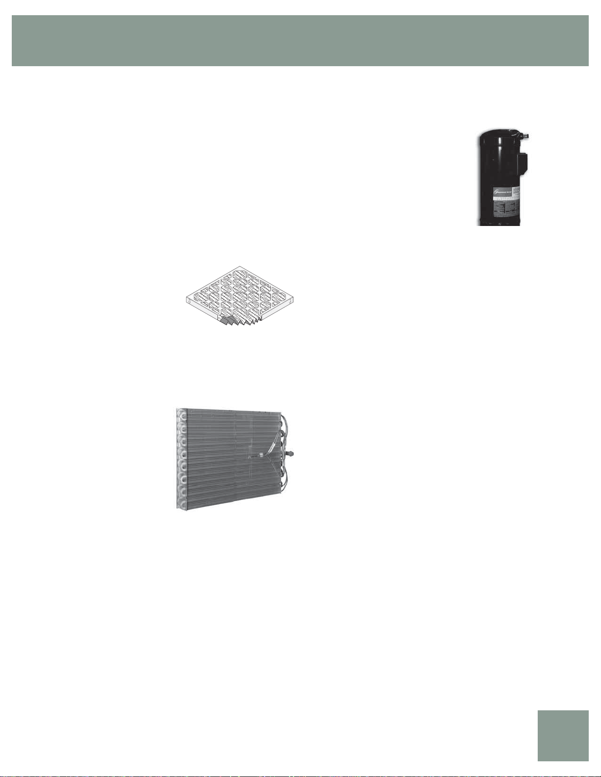
MERV 11 2” Pleated fi lter
All GT-PG units include a factory
installed 2” fi lter rack/duct collar
with a 2” pleated high effi ciency
MERV 11 air fi lter. The MERV
(minimum effi ciency reporting value
per ASHRAE Standard 52.2) design
features ultra low velocity (<300
fpm) for extended fi lter life, low pressure drop (0.13 – 0.18 in. wg.)
and high particulate effi ciency (size E1=41%, E2=69% and E3=87%).
The pleated design and low velocity combine to allow the fi lter to
store a large amount of dirt and result in a practical replacement life of
up to 6 months.
Tin-Coated Air Coil
All Bryant Geothermal GTPG Series models feature a
tin-coated air-coil. This coating
process will provide years of
protection against corrosion
from airborne chemicals
resulting from modern building
material out gassing and most
environmental chemicals found
in the air. Modern building
materials such as counter-tops,
fl oor coverings, paints and other materials can “outgas” chemicals into
the home’s air. Some of these chemicals are suspected of contributing
to corrosion in the air coils found in both traditional and geothermal
heating and cooling equipment. Corrosion often results in refrigerant
leaks and eventual failure of the air coil costing hundreds of dollars to
replace. Studies have also shown that these air coil coatings improve
moisture shedding and therefore improve a unit’s moisture removal
capability resulting in a more comfortable home. The GT-PG Series is
your assurance of both maximum air coil life and comfort.
Refrigerant
®
is a non-chlorine based (HFC-410A) refrigerant, that with
50% R-125.
Zero ozone depletion potential and low global warming potential.
two components in HFC-410A have virtually the same leak
rates. Therefore, refrigerant can be added if necessary without
recovering the charge.
MERV 11
Copeland – turned theory into practical
reality, using sophisticated, computer-assisted
design and manufacturing methods to achieve
the critical tolerances required. In the years
since, Copeland has become the leader in
scroll compressor applications, with nine scroll
manufacturing facilities on three continents and
millions of units installed worldwide.
Copeland Scroll compressors employ two
identical, concentric scrolls, one inserted
within the other. One scroll remains stationary as the other orbits
around it. This movement draws gas into the compression chamber
and moves it through successively smaller “pockets” formed by the
scroll’s rotation, until it reaches maximum pressure at the center
of the chamber. There, it’s released through a discharge port in the
fi xed scroll. During each orbit, several pockets are compressed
simultaneously, so operation is virtually continuous.
Recently, Copeland produced its 500,000th Scroll compressor with
the environmentally sound refrigerant HFC-410A. Field results have
shown that HFC-410A units with Copeland Scroll compressors offer
nearly 30% lower failure rates versus existing R-22 units. HFC-410A
units can reach the industry’s highest effi ciency levels. HFC-410A
scrolls also offer sound advantages to other compressor technologies,
typically operating several decibels quieter than comparable R-22
models. The result is unsurpassed reliability and virtually silent
operation.
Other New Features
• Powder coated cabinet, taupe metallic.
• Liftout handles for front access panels.
• Corrosion and stain resistant stainless steel drain pan with extra
slope designed in.
• Factory mounted fi lter drier for trouble free reliability.
• Easy access low profi le horizontal control box.
• Double isolated compressor for quiet and vibration
free operation.
Foil faced insulation in air handling compartment to allow easy
•
cleaning and prevent microfi ber introduction into the air stream.
• Open Service-Friendly Cabinet ( i.e, all components in
compressor section can be serviced from the front).
Copeland Scroll Compressor
There’s a reason 9 out of every 10 scroll compressors installed
are Copeland. With over 15 years of painstaking R & D and rigid
production controls, Copeland is able to build the most reliable,
effi cient and quiet scroll compressors in the world.
The concept of compressing a gas by turning one involute form – or
“scroll” – against another around a common axis is nearly a century
old. It wasn’t until the late 1980s, however that one company –
Residential Products Technical Guide
GT-PG
3
Page 4

GT-PG (50YE) Series
GT-PG Design Features
The GT-PG Series has abundant features and industry leading
effi ciency.
Application Flexibility
• Eight Capacities 018, 024, 030, 036, 042, 048, 060 and 070.
• Extended range operation (20-120°F EWT) and fl ow rates as
low as 1.5 gpm per ton.
• Vertical packages with either true right or true left return
air options.
• Internally trapped condensate drain.
• Optional variable speed ECM fan motor adapts to various
duct systems.
• Internal electric heat unit (optional) designed for easy
fi eld installation.
• Circuit breaker protected loop and hot water generator pumps.
• Field selectable low temperature protection setting for well or loop.
• Standard pre-installed 2” fi lter frame with 2” high performance
MERV 11 pleated air fi lter.*
Operating Effi ciencies
• Puron
• High effi ciencies in AHRI/ISO/ASHRAE/ANSI 13256-1 single
• Multi-speed tap PSC fan or optional ECM variable speed fan for
• Wide operating temperature range and high effi ciency allow
• Optional hot water generator with internal pump generates hot
• Rugged and highly effi cient next generation Copeland
• Oversized coaxial tube water-to-refrigerant heat exchangers
• Oversized tin-coated, rifl ed tube/lanced aluminum fi n, air to
•
Service Advantages
• Removable panels - 3 for compressor, 2 for air
• Low profi le control box grants easy access to all
• Factory installed liquid line fi lter/drier.
• Brass swivel-type water connections for quick connection and
• Bi-directional thermal expansion valve.
• CXM control features status light with memory for
• Unit Performance Sentinel alerts homeowner of potential
®
HFC-410A zero ozone depletion refrigerant.
stage ratings for heating COPs, cooling EERs with low water
fl ow rates.
ultra high effi ciencies and unsurpassed comfort.
shorter loops.
water at considerable savings.
scroll compressors provide the extremely high effi ciencies
and capacities.
operate at low liquid pressure drop. Convoluted copper (and
optional cupro-nickel) water tube functions effi ciently at low-fl ow
rates and provides freeze-damage resistance.
refrigerant heat exchangers provide high effi ciency at low
face velocity.
Large low RPM blowers with optional variable speed fan motors
provide quiet, effi cient air movement with high static capability.
handling compartment.
internal components.
elimination of wrenches or sealants during installation.
easy diagnostics.
performance issues.
• Circuit breaker protected 75VA control transformer.
• Optional ECM motor includes control board with thermostat
signal diagnostic LEDs, airfl ow display LED (100 CFM per fl ash),
and simplifi ed CFM selection.
• Insulated divider and separate air handling/compressor
compartments permit service testing without air bypass.
• Fan motors have quick attach wiring harness for fast removal.
• Internal dropout blower for easy servicing.
• High and low pressure service ports on refrigerant circuit.
• Accurate refrigerant sensing low temperature protection.
Factory Quality
• All units are built on our Integrated Process Control
Assembly System (IPCS). The IPCS is a unique state of the art
manufacturing system that is designed to assure quality of the
highest standards of any manufacturer in the water-source
industry. Our IPCS system:
- Verifi es that the correct components are being assembled.
- Automatically performs special leak tests on all joints.
- Conducts pressure tests.
- Performs highly detailed run test unparalleled in the
HVAC industry.
- Automatically disables packaging for a “failed” unit.
- Creates computer database for future service analysis and
diagnostics from run test results.
• All units are water run-tested in all modes to insure effi ciency
and reliability.
• Heavy gauge galvanized steel cabinets are epoxy powder coated
for durable and long-lasting fi nish.
• All refrigerant brazing is done in a nitrogen atmosphere.
• All units are deep evacuated to less than 100 microns prior to
refrigerant charging.
• All joints are both helium and halogen leak tested to insure
annual leak rate of less than 1/4 ounce.
• Coaxial heat exchanger, refrigerant suction lines and all water
lines are fully insulated to eliminate condensation problems in low
temperature applications.
• Noise Reduction features include: double isolation mounted
compressors; insulated compressor compartment; interior cabinet
insulation using 1/2” coated glass fi ber and optional variable
speed fan.
• Safety features include: high pressure and loss of charge to
protect the compressor; condensate overfl ow protection; low
temperature protection sensors to safeguard the coaxial heat
exchanger and air coil; hot water high-limit and low compressor
discharge temperature switch provided to shut down the hot
water generator when conditions dictate. Fault lockout enables
emergency heat and prevents compressor operation until
thermostat or circuit breaker has been reset.
Simplifi ed Controls
• CXM solid state control module.
• ‘CFM’ LED displays airfl ow (optional ECM motor).
• Dehumidifi cation mode for higher latent cooling
(optional ECM motor).
GT-PG
4
Bryant: Whatever it Takes.
Page 5
Bryant Geother mal Heat Pump Systems
Options & Accessories
• Optional hot water generator with internally mounted pump.
• Optional cupro-nickel coaxial heat exchanger.
• Electronic thermostat.
• Closed loop Flow Controller.
• Electronic auto-changeover thermostat with 3-stage heat, 2-stage
cool and indicator LEDs.
• Hose kits.
• Optional Whole House Dehumidifi cation
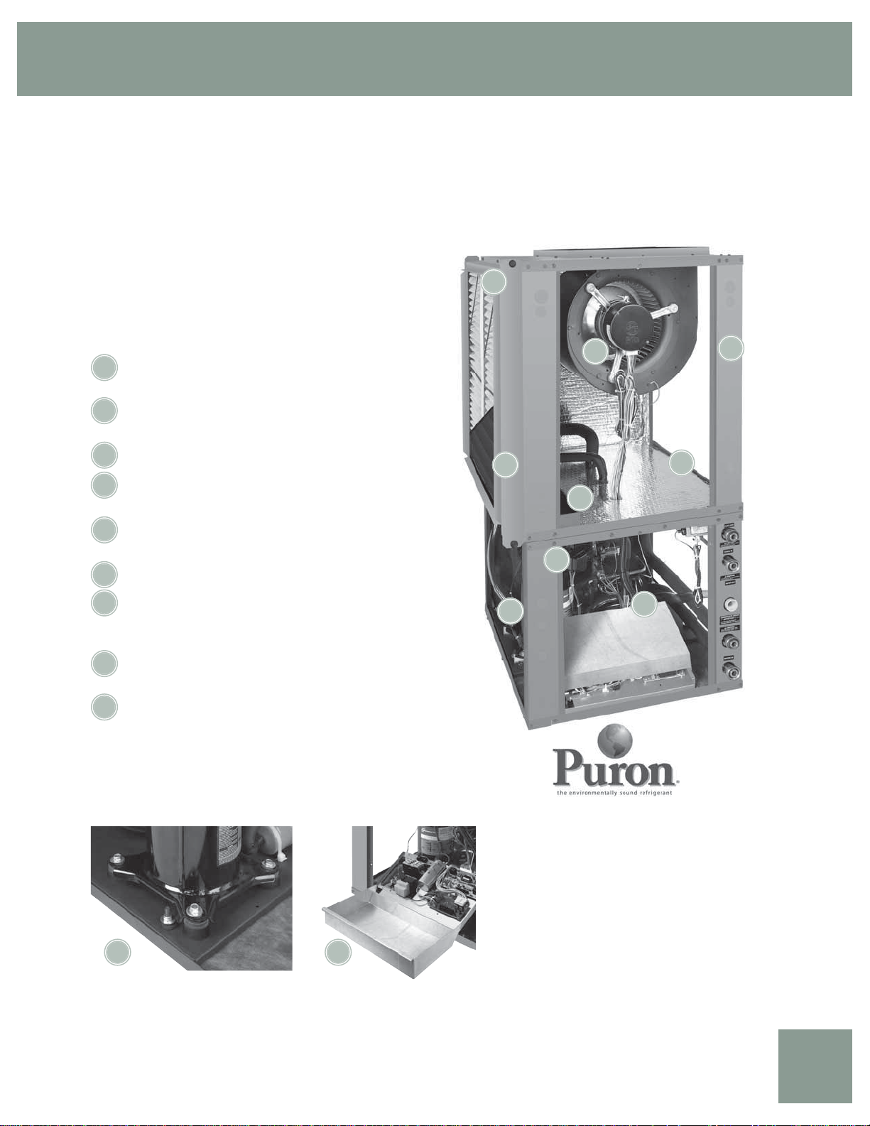
GT-PG Design Features
5
Copeland™ High Effi ciency Scroll Compressor or High
1
Effi ciency Rotary Compressor (018)
Optional State-Of-The-Ar t Variable Speed Blower
2
Motor
Tin-Coated Air Coil
3
Foil Faced Insulation In The Blower Section, Fully Insulated
4
Compressor Section
Two Inch Filter Frame With High Performance MERV 11
5
Pleated Air Filter*
Stainless Steel Drain Pan For Long Life
6
7
Unit Performance Sentinel: Automatic Alert System
Lets You Know If The System Is Not Running At Peak
Performance**
Exclusive Dual Level Compressor Vibration Isolation For
8
Ultra Quiet Operation
9
Five Easy, Lift-out Service Access Panels
With Powder Coated Cabinet, Taupe Metallic
* MERV= Minimum Effi ciency Reporting Value as specifi ed by ASHRAE (American
Society of Heating, Refrigerating and Air Conditioning Engineers) standard 52.2.
** When installed with a Bryant Geothermal Residential Thermostat.
2
3
6
1
8
4
7
9
8 7
Residential Products Technical Guide
Features Puron®
HFC-410A Zero Ozone
Depletion Refrigerant
GT-PG
5
Page 6
GT-PG (50YE) Series
Unit Model Key
5 0 J0 2 4 BC 3 1 1
Prefix
YEV = Puron Vertical Upflow Single-Stage
YEH = Puron Horizontal Single-Stage
YED = Puron Vertical Downflow Single-Stage
Option
JKLeft
L*R*Left
Option
JKLeft
L*R*Left
Option
N
P
W
Y
Z*
B*
S*
E*
* PSC motor not available on size 070
Series
018, 024, 030, 036, 042, 048, 060, 070
Air Flow Configuration
Vertical Upflow YEV
Discharge
Return
Right
Right
Vertical Downflow YED
Discharge
Return
Right
Right
Horizontal YEH
Discharge
Return
Right
Right
Left
Left
Right
Right
Left
Left
1 2 3
Y E V
Unit Size
Top
Top
Top
Top
Down
Down
Down
Down
Left
Back
Right
Back
Left
Back
Right
Back
Filter
2”
2”
2”
2”
Filter
2”
2”
2”
2”
Filter
2”
2”
2”
2”
2”
2”
2”
2”
4 5 6 7
Motor
ECM
ECM
PSC
PSC
Motor
ECM
ECM
PSC
PSC
Motor
ECM
ECM
ECM
ECM
PSC
PSC
PSC
PSC
9101112
8
Heat Exchanger Options
Without Hot Water Generator
Standard
Whole House Dehumidification
Whole House Dehumidification
w/Hot Water Generator
Controls
C = CXM
D = DXM
Revision Level
1 = 024-070
2 = 018
Voltage
3 = 280-230/60/1
Packaging
1 = Single Pack, Domestic
Coated Air Coil
Copper
Cupro-Nickel
A
B
RF
LM
J
K
GT-PG
6
Bryant: Whatever it Takes.
Page 7
Bryant Geother mal Heat Pump Systems
About AHRI/ISO/ASHRAE 13256-1
About AHRI/ISO/ASHRAE 13256-1
AHRI/ASHRAE/ISO 13256-1 (Air-Conditioning and Refrigeration Institute/American Society of Heating, Refrigerating and Air Conditioning
Engineers/International Standards Organization) is a certifi cation standard for water-source heat pumps used in the following applications:
• WLHP (Water Loop Heat Pump – Boiler/Tower)
• GWHP (Ground Water Heat Pump – Open Loop)
• GLHP (Ground Loop Heat Pump – Geothermal)
The directory at http://www.ahrinet.org/ is constantly being updated and immediately available on the Internet. All ratings are submitted by the
manufacturer for certifi cation, and must be approved by AHRI. Therefore, there is a signifi cant difference between AHRI “certifi ed” and AHRI
“rated.” Thirty percent of a manufacturer’s basic models must be tested each year. AHRI selects models at random from stock for testing on
the basis of its evaluation of a participant’s certifi cation data.
Units that fail one or more certifi ed test (90% of declared performance or lower) may be declared defective. If the initial failure is a
performance test, the manufacturer must obsolete all units within the same basic model group or elect to have a second sample tested. If the
second unit fails a performance test, it must be obsoleted, together with all units within the same basic model group. Bryant Geothermal takes
certifi cation seriously. We were recently awarded a certifi cate for consecutive years of no AHRI failures.
Temperatures used in AHRI certifi cation standards are S.I. (Système International – metric) based. For example, typical catalog data for cooling
is shown at 80°F DB/67°F WB [26.7°C DB/19.4°C] entering air temperature, but the AHRI standard for cooling is 80.6°F DB/66.2°F WB
[27°C DB/19°C], since it is based upon whole numbers in degrees Celsius. Water and air temperatures for the standard are shown below.
Test Condition Comparison Table
WLHP GWHP GLHP
Cooling
Entering Air Temperature - DB/WB °F [°C]
Entering Water Temperature - °F [°C]
Fluid Flow Rate
Heating
Entering Air Temperature - DB/WB °F [°C]
Entering Water Temperature - °F [°C]
Fluid Flow Rate
*Flow rate is specifi ed by the manufacturer
80.6/66.2 [27/19]
86 [30]
*
68 [20]
68 [20]
*
80.6/66.2 [27/19]
59 [15]
*
68 [20]
50 [10]
*
80.6/66.2 [27/19]
77 [25]
*
68 [20]
32 [0]
*
Data certifi ed by AHRI include heating/cooling capacities, EER (Energy Effi ciency Ratio – Btuh per Watt) and COP (Btuh per Btuh) at the
various conditions shown above. Pump power correction is calculated to adjust effi ciencies for pumping Watts. Within each model, only one
water fl ow rate is specifi ed for all three groups, and pumping Watts are calculated using the formula below. This additional power is added
onto the existing power consumption.
• Pump power correction = (gpm x 0.0631) x (Press Drop x 2990)/300
Fan power is corrected to zero external static pressure using the equation below. The nominal airfl ow is rated at a specifi c external static
pressure. This effectively reduces the power consumption of the unit and increases cooling capacity but decreases heating capacity.
• Fan Power Correction = (cfm x 0.472) x (esp x 249)/300
Capacities and effi ciencies are calculated using the following equations:
• ISO Cooling Capacity = Cooling Capacity (Btuh) + [Fan Power Correction (Watts) x 3.412]
• ISO EER Effi ciency (Btuh/W) =
ISO Cooling Capacity (Btuh)/[Power Input (Watts) – Fan Power Correction (Watts) + Pump Power Correction (Watts)]
• ISO Heating Capacity = Heating Capacity (Btuh) – [Fan Power Correction (Watts) x 3.412]
• ISO COP Effi ciency (Btuh/Btuh) =
ISO Heating Capacity (Btuh) x 3.412/[Power Input (Watts) - Fan Power Correction (Watts) + Pump Power Correction (Watts)]
Residential Products Technical Guide
GT-PG
7
Page 8
GT-PG (50YE) Series
AHRI/ISO/ASHRAE/ANSI 13256-1 Performance
ASHRAE/AHRI/ISO 13256-1. English (I-P) Units
Water Loop Heat Pump Ground Water Heat Pump Ground Loop Heat Pump
Model
018
TS018
TS024
024
030
TS030
TS036
036
042
TS042
TS048
048
060
TS060
TS070
070
Cooling capacities based upon 80.6°F DB, 66.2°F WB entering air temperature
Heating capacities based upon 68°F DB, 59°F WB entering air temperature
All ratings based upon operation at lower voltage of dual voltage rated models
ASHRAE/AHRI/ISO 13256-1. Metric (S-I) Units
Fan
Motor
PSC 18,600 15.0 23,000 5.2 21,300 24.8 18,800 4.5 19,500 18.4 14,500 3.6
ECM 19,200 16.5 23,300 5.9 22,100 26.3 18,900 4.9 20,200 19.4 14,500 3.9
PSC 25,100 16.2 29,600 4.9 28,600 25.7 25,000 4.3 26,300 19.1 19,000 3.7
ECM 25,000 17.0 30,000 5.3 28,100 27.4 25,100 4.6 26,000 20.0 19,400 3.8
PSC 28,200 15.3 34,900 5.0 31,700 22.9 29,400 4.4 29,400 17.6 23,600 3.8
ECM 28,600 15.6 35,200 5.3 32,200 23.9 29,400 4.6 29,800 18.0 23,700 3.9
PSC 33,000 16.6 39,800 5.5 37,300 25.1 32,900 4.8 34,500 19.2 25,700 3.9
ECM 33,100 17.6 39,500 5.8 37,300 26.5 32,900 5.1 34,600 20.2 25,800 4.2
PSC 37,400 16.0 49,400 5.4 42,900 24.3 40,100 4.6 39,300 18.4 31,600 3.8
ECM 37,800 17.1 48,600 5.7 44,200 27.1 39,300 4.9 40,000 20.0 30,400 4.0
PSC 47,000 15.3 60,000 5.0 53,900 23.3 49,000 4.4 49,900 17.6 39,000 3.7
ECM 47,600 15.9 59,700 5.2 54,100 24.6 48,700 4.5 50,100 18.5 38,400 3.8
PSC 61,000 15.9 70,400 5.0 67,000 23.2 58,700 4.5 63,300 18.2 46,500 3.7
ECM 61,000 16.4 70,800 5.2 67,200 24.3 59,100 4.6 64,000 19.0 46,700 3.8
ECM 67,000 15.2 84,900 5.0 77,000 23.5 69,000 4.4 70,000 17.8 53,900 3.6
Cooling 86°F Heating 68°F Cooling 59°F Heating 50°F Cooling 77°F Heating 32°F
Capacity
Btuh
EER
Btuh/W
Capacity
Btuh
COP
Capacity
Btuh
EER
Btuh/W
Capacity
Btuh
COP
Capacity
Btuh
EER
Btuh/W
Capacity
Btuh
COP
Water Loop Heat Pump Ground Water Heat Pump Ground Loop Heat Pump
Model
018
TS018
024
TS024
TS030
036
030
TS036
042
TS042
TS048
048
060
TS060
070
Cooling capacities based upon 27°C DB, 19°C WB entering air temperature
Heating capacities based upon 20°C DB, 15°C WB entering air temperature
All ratings based upon operation at lower voltage of dual voltage rated models
Fan
Motor
PSC 5,470 4.4 6,764 5.2 6,264 7.3 5,529 4.5 5,735 5.4 4264 3.6
ECM 5,647 4.8 6,852 5.9 6,500 7.7 5,558 4.9 5,941 5.7 4,426 3.9
PSC 7,356 4.7 8,675 4.9 8,382 7.5 7,327 4.3 7,708 5.6 5,569 3.7
ECM 7,327 5.0 8,792 5.3 8,236 8.0 7,356 4.6 7,620 5.9 5,686 3.8
PSC 8,265 4.5 10,229 5.0 9,291 6.7 8,617 4.4 8,617 5.2 6,917 3.8
ECM 8,382 4.6 10,317 5.3 9,437 7.0 8,617 4.6 8,734 5.3 6,946 3.9
PSC 9,672 4.9 11,665 5.5 10,932 7.4 9,642 4.8 10,111 5.6 7,532 3.9
ECM 9,701 5.2 11,577 5.8 10,932 7.8 9,642 5.1 10,141 5.9 7,562 4.2
PSC 10,961 4.7 14,478 5.4 12,573 7.1 11,753 4.6 11,518 5.4 9,261 3.8
ECM 11,079 5.0 14,244 5.7 12,954 7.9 11,518 4.9 11,723 5.9 8,910 4.0
PSC 13,775 4.5 17,585 5.0 15,797 6.8 14,361 4.4 14,625 5.2 11,430 3.7
ECM 13,951 4.7 17,497 5.2 15,856 7.2 14,273 4.5 14,683 5.4 11,254 3.8
PSC 17,878 4.7 20,633 5.0 19,637 6.8 17,204 4.5 18,552 5.3 13,628 3.7
ECM 17,878 4.8 20,750 5.2 19,695 7.1 17,321 4.6 18,757 5.6 13,687 3.8
ECM 19,637 4.5 24,883 5.0 22,567 6.9 20,223 4.4 20,516 5.2 15,797 3.6
Cooling 30°C Heating 20°C Cooling 15°C Heating 10°C Cooling 25°C Heating 0°C
Capacity
Watts
EER
W/W
Capacity
Watts
COP
Capacity
Watts
EER
Watts
Capacity
Watts
COP
Capacity
Watts
EER
W/W
Capacity
Watts
COP
GT-PG
8
Bryant: Whatever it Takes.
Page 9
Bryant Geother mal Heat Pump Systems
Ref er ence Calculations & Legend
Heating
LWT = EWT -
LAT = EAT +
HE
GPM x 500
HC
CFM x1.08
LWT = EWT +
LAT (DB) = EAT (DB) -
Cooling
HR
GPM x 500
SC
CFM x1.08
LC = TC - SC
SC
S/T =
TC
Hot Water Generator capacities (HWC) are based on potable water fl ow rate of 0.4 gpm per nominal equipment ton and 90°F
entering potable water temperature.
CFM = airfl ow, cubic feet/minute
EWT = entering water temperature, ˚F
GPM = water fl ow in US gallons/minute
EAT = entering air temperature, Fahrenheit (dry bulb/wet bulb)
HC = air heating capacity, Mbtuh
TC = total cooling capacity, Mbtuh
SC = sensible cooling capacity, Mbtuh
KW = total power unit input, KiloWatts
HR = total heat of rejection, Mbtuh
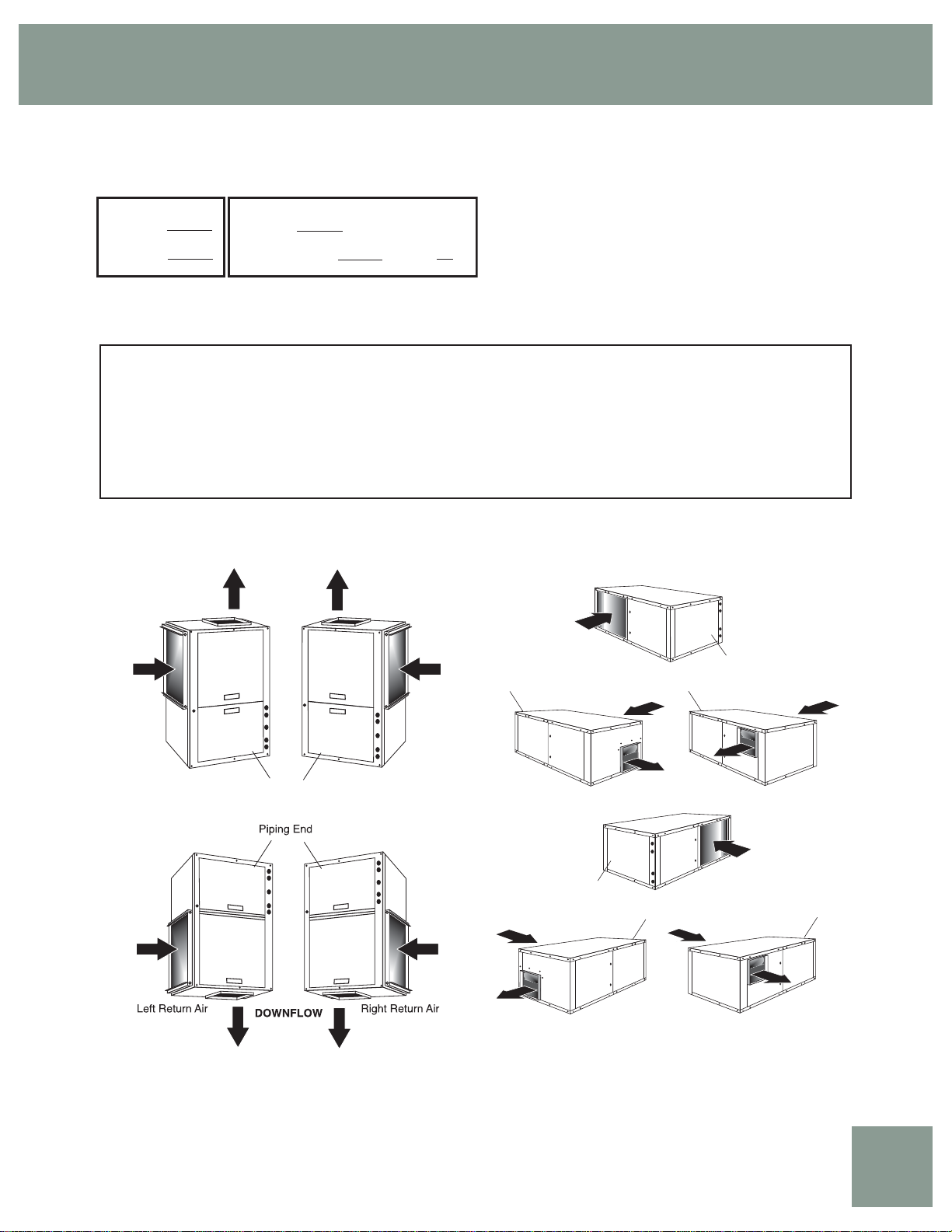
UPFLOW
HE = total heat of extraction, Mbtuh
HWC = Hot Water Generator (desuperheater) capacity, Mbtuh
WPD = Water coil pressure drop (psi & ft hd)
EER = Energy Effi ciency Ratio = BTU output/Watt input
COP = Coeffi cient of Performance = BTU output/BTU input
LWT = leaving water temperature, °F
LAT = leaving air temperature, °F
LC = latent cooling capacity, Mbtuh
S/T = sensible to total cooling ratio
LEFT RETURN AIR
Piping End
Piping End
Left Return Air
Back Discharge
Piping End
Left Return Air
Side Discharge
Left Return Air Right Return Air
Piping End
Residential Products Technical Guide
RIGHT RETURN AIR
Piping End
Right Return Air
Back Discharge
Piping End
Right Return Air
Side Discharge
Piping End
GT-PG
9
Page 10
GT-PG (50YE) Series
Air Flow Correction Factors
PSC Fan Motor
Airfl ow Cooling Heating
% of
Rated
68.75%
75%
81.25%
87.50%
93.75%
100%
106.25%
112.50%
118.75%
125%
130%
Black area denotes where operation is not recommended.
Total
Capacity
0.9465 0.8019 0.8472 0.9614 0.9496
0.9602 0.8350 0.8696 0.9675 0.9617 0.9740 1.0936 0.9425
0.9724 0.8733 0.8981 0.9744 0.9728 0.9810 1.0635 0.9592
0.9831 0.9149 0.9306 0.9821 0.9829 0.9876 1.0379 0.9744
0.9923 0.9578 0.9653 0.9906 0.9920 0.9940 1.0167 0.9880
1.0000 1.0000 1.0000 1.0000 1.0000 1.0000 1.0000 1.0000
1.0062 1.0392 1.0328 1.0102 1.0070 1.0057 0.9878 1.0105
1.0109 1.0733 1.0617 1.0211 1.0130 1.0112 0.9800 1.0194
1.0141 1.1001 1.0848 1.0329 1.0180 1.0163 0.9705 1.0284
1.0159 1.1174 1.0999 1.0455 1.0220 1.0211 0.9614 1.0368
1.0161 1.1229 1.1050 1.0562 1.0244 1.0247 0.9554 1.0430
Sensible
Capacity
S/T Power
Heat of
Rejection
Heating
Capacity
Power
Heat of
Extraction
ECM Fan Motor
Airfl ow Cooling Heating
% of
Rated
68.75%
75%
81.25%
87.50%
93.75%
100%
106.25%
112.50%
118.75%
125%
130%
Black area denotes where operation is not recommended.
Total
Capacity
0.9470 0.8265 0.8727 0.9363 0.9449
0.9619 0.8593 0.8933 0.9455 0.9587 0.9700 1.0822 0.9410
0.9747 0.8943 0.9175 0.9564 0.9711 0.9775 1.0536 0.9579
0.9853 0.9302 0.9441 0.9691 0.9821 0.9851 1.0304 0.9733
0.9938 0.9659 0.9719 0.9837 0.9918 0.9925 1.0125 0.9874
1.0000 1.0000 1.0000 1.0000 1.0000 1.0000 1.0000 1.0000
1.0041 1.0313 1.0271 1.0181 1.0069 1.0074 0.9928 1.0112
1.0060 1.0584 1.0522 1.0381 1.0123 1.0148 0.9909 1.0210
1.0070 1.0815 1.0740 1.0598 1.0174 1.0222 0.9622 1.0377
1.0076 1.0998 1.0916 1.0834 1.0225 1.0295 0.8681 1.0712
1.0083 1.1110 1.1018 1.1035 1.0271 1.0354 0.8456 1.0844
Sensible
Capacity
S/T Power
Heat of
Rejection
Heating
Capacity
Power
Heat of
Extraction
GT-PG
10
Bryant: Whatever it Takes.
Page 11
Bryant Geother mal Heat Pump Systems
Entering Air Correction Factors
Heating
Entering
Air DB°F
45
50
55
60
65
68
70
75
80
Entering
Air WB°F
50
55
60
65
66.2
67
70
75
* = Sensible capacity equals total capacity
AHRI/ISO/ASHRAE 13256-1 uses entering air conditions of Cooling - 80.6°F DB/66.2°F WB, 1
and Heating - 68°F DB/59°F WB entering air temperature
Heating
Capacity
1.0514 0.7749 1.1240
1.0426 0.8113 1.1032
1.0329 0.8525 1.0802
1.0224 0.8980 1.0551
1.0114 0.9473 1.0282
1.0046 0.9786 1.0115
1.0000 1.0000 1.0000
0.9883 1.0556 0.9706
0.9764 1.1135 0.9404
Power
Heat of
Extraction
Cooling
Total
Capacity
0.7432 0.9111 * * * * * * * * 0.9866 0.7901
0.8202 0.7709 0.8820 1.0192 * * * * * * 0.9887 0.8527
0.8960 0.6702 0.8540 1.0473 * * * * * 0.9924 0.9146
0.9705 0.6491 0.8657 1.0809 1.1066 * * * 0.9975 0.9757
0.9882 0.5939 0.8152 1.0333 1.0592 1.2481 * * 0.9990 0.9903
1.0000 0.5559 0.7801 1.0000 1.0261 1.2158 * * 1.0000 1.0000
1.0438 0.6377 0.8645 0.8913 1.0847 1.2983 * 1.0042 1.0362
1.1159 0.6008 0.6289 0.8323 1.0578 1.2773 1.0123 1.0959
60 65 70 75 80 80.6 85 90 95
Sensible Cooling Capacity Multiplier -
Entering DB °F
Power
Heat of
Rejection
Residential Products Technical Guide
GT-PG
11
Page 12
GT-PG (50YE) Series
N/A N/A 1575 47.0 5.12 30.6 98 2.69 5.3
N/A N/A 2100 48.3 4.68 32.5 91 3.02 4.5
22.3 - 1575 50.7 5.21 33.9 100 2.85 6.2
22.5 - 2100 52.1 4.77 36.0 93 3.20 5.3
23.6 - 1575 52.8 5.26 35.8 101 2.94 6.2
23.7 - 2100 54.2 4.81 37.9 94 3.30 5.3
24.2 - 1575 53.9 5.28 36.8 102 2.99 6.2
24.4 - 2100 55.4 4.83 39.0 94 3.36 5.3
22.3 - 1575 57.6 5.36 40.1 104 3.15 7.1
22.5 - 2100 59.2 4.91 42.6 96 3.53 6.1
23.5 - 1575 60.4 5.42 42.6 105 3.26 7.1
23.7 - 2100 62.0 4.96 45.2 97 3.66 6.1
24.1 - 1575 61.9 5.46 44.0 106 3.33 7.1
24.3 - 2100 63.6 4.99 46.7 98 3.74 6.1
20.5 3.6 1575 65.2 5.52 47.0 108 3.46 7.9
20.6 3.8 2100 67.0 5.05 49.9 100 3.89 6.8
22.0 3.4 1575 68.7 5.60 50.1 110 3.60 7.9
22.2 3.5 2100 70.5 5.12 53.2 101 4.04 6.8
22.8 3.1 1575 70.6 5.64 51.8 112 3.67 7.9
22.9 3.2 2100 72.5 5.15 55.0 102 4.12 6.8
18.0 4.4 1575 73.3 5.69 54.2 113 3.77 8.8
18.1 4.6 2100 75.2 5.21 57.5 103 4.24 7.5
Performance capacities shown in thousands of Btuhting
Heating - EAT 70°F
Airfl ow
CFM
HC kW HE LAT COP HW
Performance Data Selection Notes
For operation in the shaded area when water is used in
lieu of an anti-freeze solution, the LWT (Leaving Water
Temperature) must be calculated. Flow must be maintained
to a level such that the LWT is maintained above 40°F
[4.4°C] when the JW3 jumper is not clipped (see example
below). Otherwise, appropriate levels of a proper anti-freeze
should be used in systems with leaving water temperatures
of 40°F or below and the JW3 jumper should be clipped.
This is due to the potential of the refrigerant temperature
being as low as 32°F [0°C] with 40°F [4.4°C] LWT, which may
lead to a nuisance cutout due to the activation of the Low
Temperature Protection. JW3 should never be clipped for
standard range equipment or systems without antifreeze.
Example:
At 50°F EWT (Entering Water Temperature) and 1.5 gpm/
ton, a 3 ton unit has a HE of 22,500 Btuh. To calculate LWT,
rearrange the formula for HE as follows:
HE = TD x GPM x 500, where HE = Heat of Extraction (Btuh);
TD = temperature difference (EWT - LWT) and GPM = U.S.
Gallons per Minute.
TD = HE/(GPM x 500)
TD = 22,500/(4.5 x 500)
TD = 10°F
LWT = EWT - TD
LWT = 50 - 10 = 40°F
In this example, as long as the EWT does not fall below 50°F, the system will operate as designed. For EWTs below 50°F,
higher fl ow rates will be required (open loop systems, for example, require at least 2 gpm/ton when EWT is below 50°F).
Antifreeze Correction Table
Antifreeze Type
Water
Propylene Glycol
Ethylene Glycol
GT-PG
12
Methanol
Ethanol
Antifreeze
%
Total Cap Sens Cap Power Htg Cap Power
0 1.000 1.000 1.000 1.000 1.000 1.000
5 0.995 0.995 1.003 0.989 0.997 1.070
15 0.986 0.986 1.009 0.968 0.990 1.210
25 0.978 0.978 1.014 0.947 0.983 1.360
5 0.997 0.997 1.002 0.989 0.997 1.070
15 0.990 0.990 1.007 0.968 0.990 1.160
25 0.982 0.982 1.012 0.949 0.984 1.220
5 0.998 0.998 1.002 0.981 0.994 1.140
15 0.994 0.994 1.005 0.944 0.983 1.300
25 0.986 0.986 1.009 0.917 0.974 1.360
5 0.998 0.998 1.002 0.993 0.998 1.040
15 0.994 0.994 1.004 0.980 0.994 1.120
25 0.988 0.988 1.008 0.966 0.990 1.200
Cooling Heating
EWT 90°F EWT 30°F
Bryant: Whatever it Takes.
WPD
Corr. Fct.
EWT 30°F
Page 13

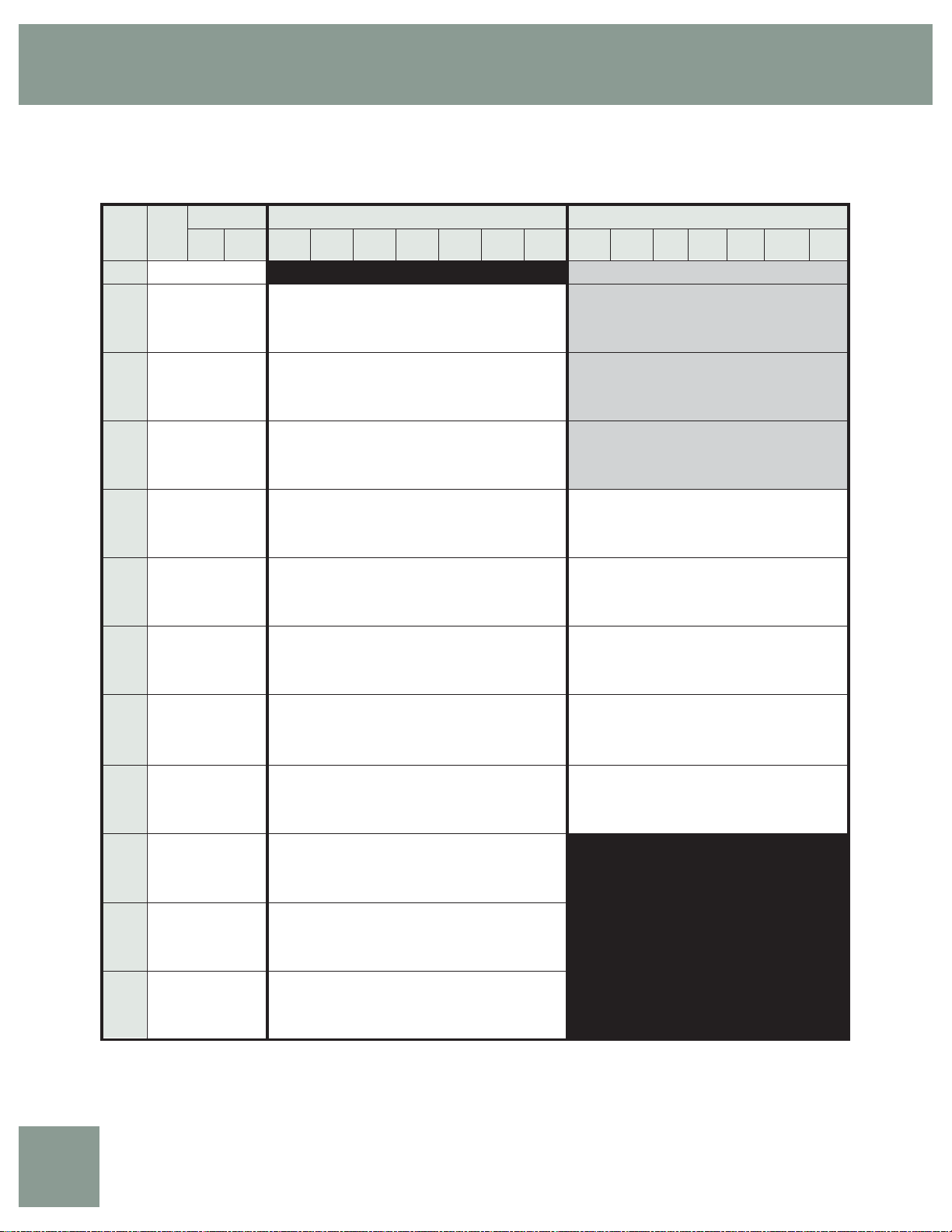
Bryant Geother mal Heat Pump Systems
Performance Data — GT-PG Model 018 - PSC Blower
600 CFM Nominal (Rated) Airfl ow Cooling, 600 CFM Nominal (Rated) Airfl ow Heating Performance capacities shown in thousands of Btuh
EWT
GPM
°F
5.5 3.9 9.0
20
5.5 3.9 9.0
2.8 0.7 1.6 450 20.7 16.8 0.78 23.3 26.6 0.5 450 13.7 1.40 9.2 98.1 2.9 1.7
2.8 0.7 1.6 600 21.5 14.0 0.80 24.3 26.8 0.6 600 14.0 1.28 9.7 91.7 3.2 1.7
4.1 2.1 4.9 450 21.0 16.8 0.74 23.5 28.4 0.5 450 14.2 1.41 9.6 99.3 2.9 1.7
30
4.1 2.1 4.9 600 21.8 14.1 0.76 24.4 28.6 0.5 600 14.6 1.29 10.2 92.5 3.3 1.8
5.5 3.5 8.1 450 21.2 16.8 0.72 23.6 29.3 0.5 450 14.5 1.42 9.9 99.9 3.0 1.8
5.5 3.5 8.1 600 22.0 14.1 0.75 24.6 29.6 0.5 600 14.9 1.30 10.5 93.0 3.4 1.8
2.8 0.6 1.4 450 20.8 17.2 0.85 23.7 24.5 0.9 450 15.8 1.44 11.1 102.6 3.2 1.9
2.8 0.6 1.4 600 21.7 14.4 0.88 24.6 24.7 0.9 600 16.3 1.32 11.8 95.1 3.6 2.0
4.1 2 4.6 450 21.0 17.2 0.81 23.7 26.0 0.8 450 16.5 1.45 11.7 103.9 3.3 2.0
40
4.1 2 4.6 600 21.8 14.4 0.83 24.7 26.2 0.9 600 16.9 1.33 12.4 96.1 3.7 2.0
5.5 3.2 7.4 450 21.2 17.3 0.79 23.9 26.9 0.8 450 16.8 1.46 12.0 104.7 3.4 2.1
5.5 3.2 7.4 600 22.1 14.5 0.81 24.8 27.1 0.8 600 17.3 1.33 12.8 96.7 3.8 2.1
2.8 0.5 1.2 450 20.6 17.3 0.95 23.9 21.8 1.4 450 18.0 1.47 13.1 107.0 3.6 2.2
2.8 0.5 1.2 600 21.5 14.5 0.98 24.8 22.0 1.5 600 18.5 1.35 13.9 98.5 4.0 2.2
4.1 1.7 3.9 450 21.0 17.5 0.89 24.0 23.5 1.3 450 18.7 1.48 13.8 108.6 3.7 2.3
50
4.1 1.7 3.9 600 21.8 14.6 0.92 25.0 23.7 1.3 600 19.2 1.35 14.6 99.7 4.2 2.3
5.5 2.8 6.5 450 21.1 17.5 0.86 24.0 24.4 1.2 450 19.2 1.49 14.2 109.4 3.8 2.3
5.5 2.8 6.5 600 21.9 14.6 0.89 25.0 24.6 1.2 600 19.7 1.36 15.1 100.4 4.2 2.4
2.8 0.3 0.7 450 19.9 16.8 1.05 23.5 18.9 1.9 450 20.1 1.50 15.1 111.4 3.9 2.4
2.8 0.3 0.7 600 20.7 14.1 1.09 24.4 19.1 2.0 600 20.7 1.37 16.0 101.9 4.4 2.5
4.1 1.5 3.5 450 20.4 17.2 0.99 23.7 20.6 1.7 450 21.0 1.51 15.9 113.3 4.1 2.5
60
4.1 1.5 3.5 600 21.2 14.3 1.02 24.7 20.8 1.8 600 21.6 1.38 16.9 103.3 4.6 2.6
5.5 2.6 6.0 450 20.6 17.3 0.96 23.8 21.5 1.6 450 21.5 1.52 16.4 114.3 4.1 2.6
5.5 2.6 6.0 600 21.4 14.4 0.99 24.8 21.7 1.6 600 22.1 1.39 17.4 104.1 4.7 2.7
2.8 0.3 0.7 450 18.9 16.2 1.17 22.9 16.1 2.6 450 22.3 1.54 17.1 115.9 4.3 2.7
2.8 0.3 0.7 600 19.7 13.5 1.21 23.8 16.2 2.7 600 22.9 1.40 18.1 105.4 4.8 2.8
4.1 1.4 3.2 450 19.5 16.6 1.10 23.2 17.7 2.3 450 23.4 1.56 18.0 118.1 4.4 2.8
70
4.1 1.4 3.2 600 20.3 13.8 1.14 24.2 17.9 2.4 600 24.0 1.43 19.1 107.0 4.9 2.9
5.5 2.4 5.5 450 19.8 16.8 1.07 23.4 18.6 2.1 450 23.9 1.57 18.5 119.3 4.5 2.9
5.5 2.4 5.5 600 20.6 14.0 1.10 24.3 18.7 2.1 600 24.6 1.44 19.7 107.9 5.0 3.0
2.8 0.2 0.5 450 17.7 15.4 1.31 22.2 13.6 3.1 450 24.6 1.59 19.1 120.6 4.5 3.0
2.8 0.2 0.5 600 18.5 12.9 1.35 23.1 13.7 3.2 600 25.2 1.46 20.3 108.9 5.1 3.0
4.1 1.2 2.8 450 18.4 15.9 1.23 22.6 15.0 2.9 450 25.8 1.63 20.2 123.1 4.6 3.1
80
4.1 1.2 2.8 600 19.2 13.2 1.27 23.5 15.1 3.0 600 26.5 1.49 21.4 110.9 5.2 3.2
5.5 2.2 5.1 450 18.7 16.1 1.19 22.8 15.7 2.6 450 26.5 1.66 20.7 124.5 4.7 3.2
5.5 2.2 5.1 600 19.5 13.4 1.23 23.7 15.9 2.7 600 27.2 1.52 22.0 111.9 5.3 3.3
2.8 0.2 0.5 450 17.1 15.0 1.39 21.9 12.4 3.4 450 25.8 1.63 20.1 123.0 4.6 3.1
2.8 0.2 0.5 600 17.8 12.6 1.43 22.7 12.5 3.6 600 26.4 1.49 21.3 110.8 5.2 3.2
4.1 1.15 2.7 450 17.8 15.5 1.30 22.2 13.7 3.2 450 27.1 1.69 21.2 125.7 4.7 3.2
85
4.1 1.15 2.7 600 18.5 12.9 1.35 23.1 13.8 3.3 600 27.8 1.54 22.5 112.9 5.3 3.3
5.5 2.1 4.9 450 18.1 15.7 1.26 22.4 14.4 2.9 450 27.8 1.72 21.8 127.2 4.7 3.3
5.5 2.1 4.9 600 18.9 13.1 1.30 23.3 14.6 3.1 600 28.6 1.58 23.2 114.1 5.3 3.4
2.8 0.2 0.5 450 16.5 14.7 1.46 21.5 11.3 3.9 450 26.9 1.68 21.1 125.4 4.7 3.2
2.8 0.2 0.5 600 17.2 12.3 1.51 22.4 11.4 4.1 600 27.7 1.53 22.4 112.7 5.3 3.3
4.1 1.1 2.5 450 17.2 15.1 1.38 21.9 12.5 3.6 450 28.4 1.74 22.3 128.3 4.8 3.3
90
4.1 1.1 2.5 600 17.9 12.6 1.42 22.8 12.6 3.8 600 29.1 1.60 23.6 114.9 5.3 3.4
5.5 2 4.6 450 17.5 15.3 1.33 22.1 13.1 3.3 450 29.1 1.79 22.9 130.0 4.8 3.5
5.5 2 4.6 600 18.3 12.8 1.38 23.0 13.2 3.5 600 29.9 1.63 24.3 116.2 5.4 3.6
2.8 0.2 0.5 450 15.2 14.0 1.64 20.8 9.3 4.3
2.8 0.2 0.5 600 15.9 11.7 1.69 21.7 9.4 4.5
4.1 1.1 2.5 450 15.9 14.3 1.54 21.2 10.3 4.1
100
4.1 1.1 2.5 600 16.6 12.0 1.59 22.0 10.4 4.3
5.5 1.9 4.4 450 16.3 14.5 1.50 21.4 10.9 4.0
5.5 1.9 4.4 600 16.9 12.1 1.55 22.2 10.9 4.2
2.8 0.1 0.2 450 14.0 13.4 1.84 20.3 7.6 5.1
2.8 0.1 0.2 600 14.6 11.2 1.90 21.1 7.7 5.3
4.1 0.9 2.1 450 14.6 13.7 1.73 20.5 8.4 5.0
110
4.1 0.9 2.1 600 15.2 11.4 1.79 21.4 8.5 5.2
5.5 1.7 3.9 450 15.0 13.8 1.68 20.7 8.9 4.8
5.5 1.7 3.9 600 15.6 11.6 1.74 21.5 9.0 5.0
2.8 0.1 0.2 450 12.9 13.1 2.06 19.9 6.2 6.1
2.8 0.1 0.2 600 13.4 10.9 2.13 20.7 6.3 6.3
4.1 0.8 1.8 450 13.4 13.2 1.94 20.1 6.9 5.9
120
4.1 0.8 1.8 600 14.0 11.0 2.01 20.8 7.0 6.1
5.5 1.6 3.7 450 13.7 13.3 1.89 20.2 7.3 5.6
Interpolation is permissible; extrapolation is not.
All entering air conditions are 80°F DB and 67°F WB in cooling, and 70°F DB in heating.
AHRI/ISO certifi ed conditions are 80.6°F DB and 66.2°F WB in cooling and 68°F DB in heating.
Table does not refl ect fan or pump power corrections for AHRI/ISO conditions.
All performance is based upon the lower voltage of dual voltage rated units.
Operation below 40°F EWT is based upon a 15% methanol antifreeze solution.
Operation below 60°F EWT requires optional insulated water/refrigerant circuit.
See performance correction tables for operating conditions other than those listed above.
For operation in the shaded areas, please see the Performance Data Selection Notes.
5.5 1.6 3.7 600 14.3 11.1 1.95 21.0 7.3 5.9
WPD Cooling - EAT 80/67°F Heating - EAT 70°F
PSI FT
Airfl ow
CFM
TC SC kW HR EER HW
Operation not recommended
Airfl ow
HC kW HE LAT COP HW
CFM
450 12.2 1.36 7.8 95.0 2.6 1.4
600 12.5 1.24 8.3 89.3 2.9 1.4
450 0.0 0.0 0.0 0.0 0.0 0.0
600 0.0 0.0 0.0 0.0 0.0 0.0
450 0.0 0.0 0.0 0.0 0.0 0.0
600 0.0 0.0 0.0 0.0 0.0 0.0
450 0.0 0.0 0.0 0.0 0.0 0.0
600 0.0 0.0 0.0 0.0 0.0 0.0
450 0.0 0.0 0.0 0.0 0.0 0.0
600 0.0 0.0 0.0 0.0 0.0 0.0
450 0.0 0.0 0.0 0.0 0.0 0.0
600 0.0 0.0 0.0 0.0 0.0 0.0
450 0.0 0.0 0.0 0.0 0.0 0.0
600 0.0 0.0 0.0 0.0 0.0 0.0
450 0.0 0.0 0.0 0.0 0.0 0.0
600 0.0 0.0 0.0 0.0 0.0 0.0
450 0.0 0.0 0.0 0.0 0.0 0.0
600 0.0 0.0 0.0 0.0 0.0 0.0
450 0.0 0.0 0.0 0.0 0.0 0.0
600 0.0 0.0 0.0 0.0 0.0 0.0
Operation not recommended
Residential Products Technical Guide
GT-PG
13
Page 14
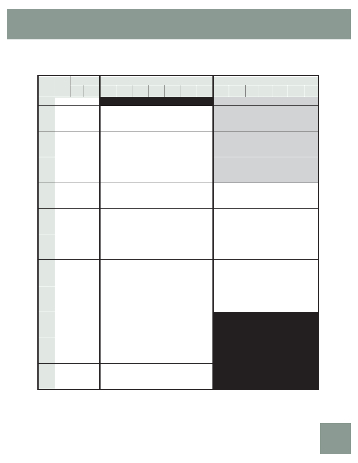
GT-PG (50YE) Series
Performance Data — GT-PG Model 018 - ECM Blower
750 CFM Nominal (Rated) Airfl ow Cooling, 750 CFM Nominal (Rated) Airfl ow Heating Performance capacities shown in thousands of Btuh
EWT
GPM
°F
5.5 3.9 9.0
20
5.5 3.9 9.0
2.8 0.7 1.6 550 20.3 12.4 0.75 22.8 27.3 0.6 550 13.2 1.29 9.0 92.3 3.0 1.7
2.8 0.7 1.6 750 21.1 14.5 0.79 23.8 26.8 0.6 750 13.6 1.20 9.6 86.8 3.3 1.7
4.1 2.1 4.9 550 20.7 12.6 0.71 23.1 29.1 0.5 550 13.7 1.31 9.5 93.1 3.1 1.8
30
4.1 2.1 4.9 750 21.5 14.7 0.75 24.1 28.6 0.6 750 14.1 1.21 10.1 87.5 3.4 1.8
5.5 3.5 8.1 550 21.3 12.9 0.70 23.6 30.5 0.5 550 14.0 1.31 9.7 93.6 3.1 1.8
5.5 3.5 8.1 750 22.1 15.0 0.74 24.6 30.0 0.5 750 14.4 1.21 10.3 87.8 3.5 1.9
2.8 0.6 1.4 550 20.8 12.9 0.81 23.5 25.5 0.9 550 15.3 1.33 10.9 95.8 3.4 1.9
2.8 0.6 1.4 750 21.6 15.0 0.86 24.5 25.1 1.0 750 15.8 1.23 11.6 89.5 3.8 2.0
4.1 2.0 4.6 550 21.3 13.1 0.77 23.9 27.6 0.9 550 16.0 1.34 11.5 96.9 3.5 2.0
40
4.1 2.0 4.6 750 22.1 15.2 0.81 24.9 27.2 0.9 750 16.5 1.24 12.3 90.3 3.9 2.1
5.5 3.2 7.4 550 21.5 13.2 0.75 24.0 28.6 0.8 550 16.3 1.34 11.9 97.5 3.6 2.1
5.5 3.2 7.4 750 22.4 15.3 0.79 25.1 28.1 0.8 750 16.8 1.24 12.6 90.8 4.0 2.1
2.8 0.5 1.2 550 21.3 13.5 0.90 24.3 23.7 1.5 550 17.5 1.35 13.0 99.5 3.8 2.2
2.8 0.5 1.2 750 22.1 15.7 0.95 25.3 23.3 1.5 750 18.1 1.25 13.8 92.3 4.2 2.3
4.1 1.7 3.9 550 21.5 13.5 0.84 24.3 25.5 1.3 550 18.4 1.36 13.8 100.9 4.0 2.3
50
4.1 1.7 3.9 750 22.3 15.7 0.89 25.4 25.1 1.4 750 18.9 1.26 14.6 93.4 4.4 2.4
5.5 2.8 6.5 550 21.6 13.5 0.82 24.4 26.4 1.2 550 18.8 1.36 14.2 101.7 4.0 2.4
5.5 2.8 6.5 750 22.5 15.7 0.87 25.4 26.0 1.3 750 19.4 1.26 15.1 93.9 4.5 2.4
2.8 0.3 0.7 550 20.6 13.6 0.99 24.0 20.8 2.0 550 19.8 1.37 15.2 103.4 4.2 2.5
2.8 0.3 0.7 750 21.5 15.8 1.05 25.0 20.4 2.1 750 20.4 1.27 16.1 95.2 4.7 2.6
4.1 1.5 3.5 550 21.1 13.6 0.93 24.3 22.7 1.8 550 20.8 1.38 16.1 105.0 4.4 2.6
60
4.1 1.5 3.5 750 22.0 15.9 0.99 25.3 22.3 1.9 750 21.4 1.28 17.1 96.5 4.9 2.6
5.5 2.6 6.0 550 21.3 13.6 0.90 24.4 23.6 1.6 550 21.3 1.39 16.6 105.9 4.5 2.7
5.5 2.6 6.0 750 22.2 15.9 0.96 25.4 23.2 1.7 750 22.0 1.28 17.6 97.1 5.0 2.7
2.8 0.3 0.7 550 19.6 13.4 1.11 23.4 17.7 2.7 550 22.1 1.40 17.3 107.2 4.6 2.8
2.8 0.3 0.7 750 20.4 15.6 1.17 24.4 17.4 2.8 750 22.8 1.29 18.4 98.2 5.2 2.8
4.1 1.4 3.2 550 20.3 13.5 1.04 23.8 19.5 2.4 550 23.2 1.42 18.3 109.0 4.8 2.9
70
4.1 1.4 3.2 750 21.1 15.7 1.10 24.8 19.2 2.5 750 23.9 1.31 19.4 99.5 5.3 2.9
5.5 2.4 5.5 550 20.6 13.6 1.00 24.0 20.5 2.1 550 23.8 1.43 18.8 110.0 4.9 3.0
5.5 2.4 5.5 750 21.4 15.8 1.06 25.0 20.1 2.2 750 24.5 1.32 20.0 100.2 5.4 3.1
2.8 0.2 0.5 550 18.4 13.1 1.24 22.7 14.8 3.2 550 24.3 1.45 19.3 111.0 4.9 3.0
2.8 0.2 0.5 750 19.2 15.2 1.31 23.6 14.6 3.3 750 25.1 1.34 20.5 101.0 5.5 3.1
4.1 1.2 2.8 550 19.1 13.3 1.16 23.1 16.5 3.0 550 25.5 1.49 20.3 112.9 5.0 3.1
80
4.1 1.2 2.8 750 19.9 15.4 1.23 24.1 16.2 3.1 750 26.3 1.38 21.5 102.4 5.6 3.2
5.5 2.2 5.1 550 19.5 13.4 1.12 23.3 17.3 2.7 550 26.0 1.52 20.7 113.8 5.0 3.2
5.5 2.2 5.1 750 20.3 15.5 1.19 24.3 17.0 2.9 750 26.8 1.40 22.0 103.1 5.6 3.3
2.8 0.2 0.5 550 17.8 12.9 1.32 22.3 13.5 3.6 550 25.4 1.49 20.2 112.7 5.0 3.1
2.8 0.2 0.5 750 18.5 15.0 1.40 23.3 13.3 3.7 750 26.2 1.38 21.4 102.3 5.6 3.2
4.1 1.15 2.7 550 18.5 13.1 1.24 22.7 15.1 3.3 550 26.5 1.55 21.1 114.6 5.0 3.3
85
4.1 1.15 2.7 750 19.2 15.2 1.31 23.7 14.8 3.5 750 27.3 1.43 22.4 103.7 5.6 3.3
5.5 2.1 4.9 550 18.9 13.2 1.20 22.9 15.9 3.1 550 27.0 1.59 21.5 115.5 5.0 3.4
5.5 2.1 4.9 750 19.6 15.3 1.26 23.9 15.6 3.2 750 27.9 1.47 22.8 104.4 5.6 3.5
2.8 0.2 0.5 550 17.2 12.7 1.40 21.9 12.3 4.1 550 26.4 1.54 21.0 114.5 5.0 3.3
2.8 0.2 0.5 750 17.8 14.8 1.48 22.9 12.1 4.3 750 27.2 1.42 22.4 103.6 5.6 3.4
4.1 1.1 2.5 550 17.9 12.9 1.31 22.3 13.7 3.8 550 27.5 1.61 21.9 116.3 5.0 3.4
90
4.1 1.1 2.5 750 18.6 15.0 1.38 23.3 13.4 3.9 750 28.4 1.49 23.2 105.0 5.6 3.5
5.5 2.0 4.6 550 18.2 13.0 1.27 22.6 14.4 3.5 550 28.0 1.66 22.3 117.2 5.0 3.5
5.5 2.0 4.6 750 19.0 15.2 1.34 23.5 14.2 3.6 750 28.9 1.53 23.6 105.7 5.5 3.6
2.8 0.2 0.5 550 15.9 12.3 1.58 21.3 10.1 4.5
2.8 0.2 0.5 750 16.5 14.3 1.67 22.2 9.9 4.7
100
110
120
Interpolation is permissible; extrapolation is not.
All entering air conditions are 80°F DB and 67°F WB in cooling, and 70°F DB in heating.
AHRI/ISO certifi ed conditions are 80.6°F DB and 66.2°F WB in cooling and 68°F DB in heating.
Table does not refl ect fan or pump power corrections for AHRI/ISO conditions.
All performance is based upon the lower voltage of dual voltage rated units.
Operation below 40°F EWT is based upon a 15% methanol antifreeze solution.
Operation below 60°F EWT requires optional insulated water/refrigerant circuit.
See performance correction tables for operating conditions other than those listed above.
For operation in the shaded areas, please see the Performance Data Selection Notes.
4.1 1.1 2.5 550 16.6 12.5 1.48 21.6 11.2 4.3
4.1 1.1 2.5 750 17.2 14.6 1.56 22.6 11.0 4.5
5.5 1.9 4.4 550 16.9 12.6 1.43 21.8 11.8 4.2
5.5 1.9 4.4 750 17.6 14.7 1.51 22.8 11.6 4.3
2.8 0.1 0.2 550 14.7 12.0 1.79 20.9 8.3 5.4
2.8 0.1 0.2 750 15.3 13.9 1.89 21.8 8.1 5.6
4.1 0.9 2.1 550 15.3 12.1 1.67 21.1 9.2 5.2
4.1 0.9 2.1 750 15.9 14.1 1.77 22.0 9.0 5.4
5.5 1.7 3.9 550 15.6 12.2 1.62 21.2 9.7 5.0
5.5 1.7 3.9 750 16.3 14.2 1.71 22.1 9.5 5.2
2.8 0.1 0.2 550 13.8 11.5 2.03 20.8 6.8 6.3
2.8 0.1 0.2 750 14.4 13.4 2.14 21.7 6.7 6.6
4.1 0.8 1.8 550 14.3 11.8 1.90 20.8 7.5 6.1
4.1 0.8 1.8 750 14.8 13.7 2.01 21.7 7.4 6.3
5.5 1.6 3.7 550 14.5 11.9 1.83 20.8 7.9 5.9
5.5 1.6 3.7 750 15.1 13.9 1.94 21.7 7.8 6.1
WPD Cooling - EAT 80/67°F Heating - EAT 70°F
PSI FT
Airfl ow
TC SC kW HR EER HW
CFM
550 0.0 0.0 0.00 0.0 0.0 0.0 550 11.9 1.25 7.9 90.0 2.8 1.4
750 0.0 0.0 0.00 0.0 0.0 0.0 750 12.3 1.16 8.4 85.1 3.1 1.5
Operation not recommended
Airfl ow
HC kW HE LAT COP HW
CFM
550 0.0 0.0 0.0 0.0 0.0 0.0
750 0.0 0.0 0.0 0.0 0.0 0.0
550 0.0 0.0 0.0 0.0 0.0 0.0
750 0.0 0.0 0.0 0.0 0.0 0.0
550 0.0 0.0 0.0 0.0 0.0 0.0
750 0.0 0.0 0.0 0.0 0.0 0.0
550 0.0 0.0 0.0 0.0 0.0 0.0
750 0.0 0.0 0.0 0.0 0.0 0.0
550 0.0 0.0 0.0 0.0 0.0 0.0
750 0.0 0.0 0.0 0.0 0.0 0.0
550 0.0 0.0 0.0 0.0 0.0 0.0
750 0.0 0.0 0.0 0.0 0.0 0.0
550 0.0 0.0 0.0 0.0 0.0 0.0
750 0.0 0.0 0.0 0.0 0.0 0.0
550 0.0 0.0 0.0 0.0 0.0 0.0
750 0.0 0.0 0.0 0.0 0.0 0.0
550 0.0 0.0 0.0 0.0 0.0 0.0
750 0.0 0.0 0.0 0.0 0.0 0.0
Operation not recommended
GT-PG
14
Bryant: Whatever it Takes.
Page 15
Bryant Geother mal Heat Pump Systems
Performance Data — GT-PG Model 024 - PSC Blower
850 CFM Nominal (Rated) Airfl ow Cooling, 850 CFM Nominal (Rated) Airfl ow Heating Performance capacities shown in thousands of Btuh
EWT
GPM
°F
8.0 5.6 12.9
20
8.0 5.6 12.9
4.0 1.5 3.5 640 27.9 15.6 0.94 31.1 29.8 0.6 640 18.5 1.83 12.5 97 2.95 2.0
4.0 1.5 3.5 850 29.1 18.7 0.97 32.4 30.0 0.6 850 19.0 1.68 13.3 91 3.32 2.0
6.0 3.1 7.2 640 28.0 15.6 0.90 31.1 31.1 0.5 640 19.2 1.84 13.2 98 3.05 2.0
30
6.0 3.1 7.2 850 29.2 18.7 0.93 32.4 31.3 0.6 850 19.7 1.68 14.0 91 3.42 2.1
8.0 5.1 11.8 640 28.1 15.7 0.88 31.1 31.8 0.5 640 19.5 1.85 13.5 98 3.10 2.1
8.0 5.1 11.8 850 29.3 18.8 0.91 32.4 32.1 0.5 850 20.0 1.69 14.3 92 3.48 2.2
4.0 1.3 3.0 640 27.8 15.8 1.04 31.3 26.9 1.0 640 21.4 1.87 15.2 101 3.34 2.3
4.0 1.3 3.0 850 29.0 18.9 1.07 32.6 27.1 1.0 850 22.0 1.71 16.1 94 3.75 2.3
6.0 2.8 6.5 640 28.0 15.8 0.99 31.4 28.5 0.9 640 22.2 1.89 16.0 102 3.45 2.3
40
6.0 2.8 6.5 850 29.2 18.9 1.02 32.6 28.7 0.9 850 22.8 1.72 17.0 95 3.87 2.4
8.0 4.5 10.4 640 28.2 15.8 0.96 31.4 29.3 0.8 640 22.6 1.89 16.4 103 3.51 2.4
8.0 4.5 10.4 850 29.3 18.9 0.99 32.7 29.5 0.9 850 23.3 1.73 17.4 95 3.94 2.5
4.0 1.3 3.0 640 27.6 15.9 1.15 31.5 24.1 1.5 640 24.2 1.92 17.8 105 3.71 2.6
4.0 1.3 3.0 850 28.7 19.0 1.18 32.7 24.3 1.6 850 24.9 1.75 18.9 97 4.16 2.6
6.0 2.6 6.0 640 27.8 15.9 1.08 31.5 25.7 1.4 640 25.2 1.93 18.7 106 3.82 2.7
50
6.0 2.6 6.0 850 29.0 19.1 1.12 32.8 25.9 1.5 850 25.9 1.76 19.9 98 4.29 2.7
8.0 4.3 9.9 640 27.9 15.9 1.06 31.5 26.5 1.3 640 25.7 1.94 19.2 107 3.89 2.8
8.0 4.3 9.9 850 29.1 19.1 1.09 32.8 26.7 1.3 850 26.4 1.77 20.3 99 4.36 2.8
4.0 1.2 2.8 640 26.9 15.9 1.27 31.2 21.1 2.1 640 27.0 1.96 20.4 109 4.05 2.9
4.0 1.2 2.8 850 28.0 19.1 1.32 32.5 21.3 2.2 850 27.7 1.79 21.7 100 4.54 3.0
6.0 2.5 5.8 640 27.3 15.9 1.20 31.4 22.7 1.9 640 28.1 1.97 21.4 111 4.17 3.0
60
6.0 2.5 5.8 850 28.4 19.1 1.24 32.6 22.9 2.0 850 28.8 1.80 22.7 101 4.68 3.1
8.0 4.0 9.2 640 27.5 15.9 1.17 31.4 23.5 1.7 640 28.6 1.98 21.9 111 4.23 3.1
8.0 4.0 9.2 850 28.6 19.1 1.21 32.7 23.7 1.8 850 29.4 1.81 23.2 102 4.75 3.2
4.0 1.1 2.5 640 26.0 15.8 1.42 30.8 18.2 2.8 640 29.7 2.00 22.9 113 4.36 3.2
4.0 1.1 2.5 850 27.0 18.9 1.47 32.0 18.4 3.0 850 30.5 1.83 24.3 103 4.89 3.3
6.0 2.3 5.3 640 26.5 15.9 1.34 31.1 19.8 2.5 640 30.8 2.02 23.9 115 4.48 3.3
70
6.0 2.3 5.3 850 27.6 19.0 1.39 32.3 19.9 2.6 850 31.7 1.84 25.4 104 5.04 3.4
8.0 3.8 8.8 640 26.7 15.9 1.30 31.2 20.5 2.3 640 31.4 2.02 24.5 115 4.55 3.5
8.0 3.8 8.8 850 27.8 19.0 1.35 32.4 20.7 2.3 850 32.3 1.85 25.9 105 5.11 3.6
4.0 1.0 2.3 640 24.8 15.6 1.59 30.2 15.6 3.4 640 32.3 2.04 25.3 117 4.65 3.5
4.0 1.0 2.3 850 25.8 18.6 1.65 31.5 15.7 3.5 850 33.2 1.86 26.8 106 5.22 3.6
6.0 2.2 5.1 640 25.4 15.7 1.50 30.6 16.9 3.1 640 33.5 2.06 26.3 118 4.77 3.6
80
6.0 2.2 5.1 850 26.5 18.8 1.55 31.8 17.1 3.3 850 34.4 1.88 27.9 107 5.36 3.7
8.0 3.5 8.1 640 25.7 15.8 1.46 30.7 17.7 2.9 640 34.1 2.07 26.9 119 4.83 3.8
8.0 3.5 8.1 850 26.8 18.9 1.51 31.9 17.8 3.0 850 35.0 1.89 28.5 108 5.43 3.9
4.0 1.0 2.3 640 24.1 15.4 1.69 29.9 14.3 3.8 640 33.5 2.06 26.4 119 4.78 3.7
4.0 1.0 2.3 850 25.1 18.4 1.75 31.1 14.4 3.9 850 34.4 1.88 28.0 108 5.36 3.8
6.0 2.2 5.0 640 24.8 15.5 1.59 30.2 15.6 3.5 640 34.7 2.08 27.5 120 4.90 3.8
85
6.0 2.2 5.0 850 25.8 18.6 1.65 31.5 15.7 3.7 850 35.7 1.90 29.2 109 5.50 3.9
8.0 3.5 8.0 640 25.1 15.6 1.55 30.4 16.2 3.2 640 35.4 2.09 28.0 121 4.96 3.9
8.0 3.5 8.0 850 26.2 18.7 1.60 31.6 16.4 3.4 850 36.3 1.91 29.8 110 5.57 4.1
4.0 1.0 2.3 640 23.5 15.2 1.79 29.6 13.1 4.3 640 34.8 2.08 27.5 120 4.90 3.8
4.0 1.0 2.3 850 24.4 18.2 1.85 30.8 13.2 4.5 850 35.7 1.90 29.2 109 5.51 3.9
6.0 2.1 4.9 640 24.2 15.4 1.69 29.9 14.3 4.0 640 36.0 2.10 28.6 122 5.03 4.0
90
6.0 2.1 4.9 850 25.2 18.4 1.74 31.1 14.4 4.2 850 37.0 1.92 30.4 110 5.64 4.1
8.0 3.4 7.9 640 24.5 15.5 1.64 30.1 15.0 3.7 640 36.6 2.11 29.2 123 5.09 4.1
8.0 3.4 7.9 850 25.5 18.5 1.69 31.3 15.1 3.8 850 37.6 1.93 31.0 111 5.71 4.2
4.0 1.0 2.3 640 21.9 14.7 2.02 28.8 10.9 4.7
4.0 1.0 2.3 850 22.8 17.6 2.08 30.0 11.0 4.9
6.0 2.0 4.6 640 22.7 14.9 1.90 29.2 12.0 4.6
100
6.0 2.0 4.6 850 23.7 17.9 1.96 30.4 12.0 4.7
8.0 3.2 7.4 640 23.1 15.1 1.84 29.4 12.5 4.4
8.0 3.2 7.4 850 24.1 18.1 1.91 30.6 12.6 4.6
4.0 0.9 2.1 640 20.2 14.0 2.27 28.0 8.9 5.7
4.0 0.9 2.1 850 21.1 16.8 2.34 29.1 9.0 5.9
6.0 1.9 4.4 640 21.1 14.4 2.14 28.4 9.8 5.5
110
6.0 1.9 4.4 850 22.0 17.2 2.21 29.5 9.9 5.7
8.0 3.1 7.2 640 21.5 14.5 2.08 28.6 10.3 5.3
8.0 3.1 7.2 850 22.4 17.4 2.15 29.7 10.4 5.5
4.0 0.9 2.1 640 18.4 13.2 2.55 27.1 7.2 6.7
4.0 0.9 2.1 850 19.2 15.8 2.64 28.2 7.3 7.0
6.0 1.8 4.2 640 19.3 13.6 2.41 27.5 8.0 6.5
120
6.0 1.8 4.2 850 20.1 16.3 2.49 28.6 8.1 6.7
8.0 3.0 6.9 640 19.7 13.8 2.35 27.8 8.4 6.2
Interpolation is permissible; extrapolation is not.
All entering air conditions are 80°F DB and 67°F WB in cooling, and 70°F DB in heating.
AHRI/ISO certifi ed conditions are 80.6°F DB and 66.2°F WB in cooling and 68°F DB in heating.
Table does not refl ect fan or pump power corrections for AHRI/ISO conditions.
All performance is based upon the lower voltage of dual voltage rated units.
Operation below 40°F EWT is based upon a 15% methanol antifreeze solution.
Operation below 60°F EWT requires optional insulated water/refrigerant circuit.
See performance correction tables for operating conditions other than those listed above.
For operation in the shaded areas, please see the Performance Data Selection Notes.
8.0 3.0 6.9 850 20.6 16.5 2.42 28.9 8.5 6.5
WPD Cooling - EAT 80/67°F Heating - EAT 70°F
PSI FT
Airfl ow
TC SC kW HR EER HW
CFM
N/A N/A N/A N/A N/A N/A N/A 640 16.3 1.80 10.6 94 2.66 1.6
N/A N/A N/A N/A N/A N/A N/A 850 16.8 1.65 11.2 88 2.99 1.7
Operation not recommended
Airfl ow
HC kW HE LAT COP HW
CFM
N/A N/A N/A N/A N/A N/A
N/A N/A N/A N/A N/A N/A
N/A N/A N/A N/A N/A N/A
N/A N/A N/A N/A N/A N/A
N/A N/A N/A N/A N/A N/A
N/A N/A N/A N/A N/A N/A
N/A N/A N/A N/A N/A N/A
N/A N/A N/A N/A N/A N/A
N/A N/A N/A N/A N/A N/A
N/A N/A N/A N/A N/A N/A
N/A N/A N/A N/A N/A N/A
N/A N/A N/A N/A N/A N/A
N/A N/A N/A N/A N/A N/A
N/A N/A N/A N/A N/A N/A
N/A N/A N/A N/A N/A N/A
N/A N/A N/A N/A N/A N/A
N/A N/A N/A N/A N/A N/A
N/A N/A N/A N/A N/A N/A
Operation not recommended
Residential Products Technical Guide
GT-PG
15
Page 16

GT-PG (50YE) Series
Performance Data — GT-PG Model 024 - ECM Blower
850 CFM Nominal (Rated) Airfl ow Cooling, 950 CFM Nominal (Rated) Airfl ow Heating Performance capacities shown in thousands of Btuh
EWT
GPM
°F
8.0 5.6 12.9
20
8.0 5.6 12.9
4.0 1.5 3.5 610 28.1 16.1 0.78 30.6 35.9 0.6 690 18.1 1.73 12.5 94 3.07 2.0
4.0 1.5 3.5 850 29.2 18.7 0.83 31.9 35.3 0.6 950 18.7 1.60 13.3 88 3.43 2.0
6.0 3.1 7.2 610 28.1 16.1 0.76 30.6 37.1 0.5 690 18.8 1.74 13.2 95 3.17 2.1
30
6.0 3.1 7.2 850 29.3 18.7 0.80 31.9 36.5 0.6 950 19.4 1.61 14.0 89 3.54 2.1
8.0 5.1 11.8 610 28.2 16.1 0.74 30.7 38.1 0.5 690 19.2 1.74 13.5 96 3.23 2.1
8.0 5.1 11.8 850 29.3 18.8 0.78 32.0 37.5 0.5 950 19.8 1.61 14.3 89 3.60 2.2
4.0 1.3 3.0 610 28.4 16.6 0.89 31.3 31.9 1.0 690 21.0 1.77 15.2 98 3.48 2.3
4.0 1.3 3.0 850 29.5 19.3 0.94 32.7 31.3 1.0 950 21.7 1.64 16.1 91 3.89 2.3
6.0 2.8 6.5 610 28.6 16.6 0.84 31.4 34.1 0.9 690 21.9 1.78 16.0 99 3.60 2.4
40
6.0 2.8 6.5 850 29.7 19.3 0.89 32.7 33.5 0.9 950 22.5 1.65 17.0 92 4.01 2.4
8.0 4.5 10.4 610 28.7 16.6 0.82 31.4 35.2 0.8 690 22.3 1.79 16.4 100 3.65 2.5
8.0 4.5 10.4 850 29.9 19.3 0.86 32.8 34.6 0.9 950 23.0 1.65 17.4 92 4.08 2.5
4.0 1.3 3.0 610 28.2 16.7 1.00 31.5 28.1 1.5 690 23.9 1.81 17.8 102 3.86 2.6
4.0 1.3 3.0 850 29.3 19.4 1.06 32.9 27.7 1.6 950 24.6 1.67 18.9 94 4.31 2.7
6.0 2.6 6.0 610 28.5 16.8 0.94 31.6 30.4 1.4 690 24.8 1.83 18.7 103 3.99 2.7
50
6.0 2.6 6.0 850 29.7 19.5 0.99 33.0 29.8 1.5 950 25.6 1.69 19.9 95 4.45 2.8
8.0 4.3 9.9 610 28.6 16.8 0.91 31.7 31.5 1.3 690 25.3 1.83 19.1 104 4.05 2.8
8.0 4.3 9.9 850 29.8 19.5 0.96 33.0 30.9 1.3 950 26.1 1.69 20.3 95 4.52 2.9
4.0 1.2 2.8 610 27.3 16.4 1.13 31.1 24.1 2.1 690 26.7 1.85 20.4 106 4.22 2.9
4.0 1.2 2.8 850 28.4 19.1 1.20 32.5 23.7 2.2 950 27.5 1.71 21.7 97 4.71 3.0
6.0 2.5 5.8 610 27.8 16.6 1.06 31.4 26.3 1.9 690 27.7 1.87 21.3 107 4.35 3.0
60
6.0 2.5 5.8 850 28.9 19.3 1.12 32.7 25.8 2.0 950 28.6 1.73 22.7 98 4.85 3.1
8.0 4.0 9.2 610 28.1 16.7 1.02 31.5 27.4 1.7 690 28.3 1.88 21.8 108 4.41 3.2
8.0 4.0 9.2 850 29.2 19.4 1.08 32.8 26.9 1.8 950 29.1 1.73 23.2 98 4.92 3.2
4.0 1.1 2.5 610 26.1 16.0 1.28 30.5 20.4 2.8 690 29.4 1.89 22.8 109 4.54 3.3
4.0 1.1 2.5 850 27.2 18.7 1.36 31.8 20.0 3.0 950 30.3 1.75 24.3 99 5.07 3.4
6.0 2.3 5.3 610 26.8 16.3 1.20 30.8 22.3 2.5 690 30.5 1.91 23.9 111 4.67 3.4
70
6.0 2.3 5.3 850 27.9 18.9 1.27 32.2 22.0 2.6 950 31.4 1.77 25.4 101 5.21 3.5
8.0 3.8 8.8 610 27.1 16.4 1.16 31.0 23.4 2.3 690 31.1 1.92 24.4 112 4.74 3.5
8.0 3.8 8.8 850 28.2 19.1 1.23 32.3 23.0 2.3 950 32.0 1.77 25.9 101 5.29 3.6
4.0 1.0 2.3 610 24.8 15.6 1.45 29.7 17.1 3.4 690 31.9 1.93 25.2 113 4.84 3.6
4.0 1.0 2.3 850 25.8 18.1 1.54 31.0 16.8 3.5 950 32.9 1.79 26.8 102 5.40 3.7
6.0 2.2 5.1 610 25.5 15.8 1.36 30.1 18.7 3.1 690 33.1 1.95 26.3 114 4.97 3.7
80
6.0 2.2 5.1 850 26.5 18.4 1.44 31.4 18.4 3.3 950 34.1 1.80 27.9 103 5.54 3.8
8.0 3.5 8.1 610 25.9 15.9 1.32 30.3 19.6 2.9 690 33.7 1.96 26.9 115 5.04 3.8
8.0 3.5 8.1 850 26.9 18.6 1.39 31.6 19.3 3.0 950 34.8 1.81 28.5 104 5.62 3.9
4.0 1.0 2.3 610 24.0 15.3 1.55 29.3 15.5 3.8 690 33.2 1.95 26.3 114 4.98 3.7
4.0 1.0 2.3 850 25.0 17.8 1.64 30.6 15.2 3.9 950 34.2 1.80 28.0 103 5.55 3.8
6.0 2.2 5.0 610 24.8 15.6 1.45 29.7 17.0 3.5 690 34.3 1.97 27.4 116 5.10 3.9
85
6.0 2.2 5.0 850 25.8 18.1 1.54 31.0 16.8 3.7 950 35.4 1.82 29.2 105 5.69 4.0
8.0 3.5 8.0 610 25.1 15.7 1.41 29.9 17.9 3.2 690 35.0 1.98 28.0 117 5.17 4.0
8.0 3.5 8.0 850 26.1 18.3 1.49 31.2 17.6 3.4 950 36.0 1.83 29.8 105 5.77 4.1
4.0 1.0 2.3 610 23.3 15.0 1.65 28.9 14.1 4.3 690 34.4 1.97 27.5 116 5.11 3.9
4.0 1.0 2.3 850 24.2 17.5 1.74 30.2 13.9 4.5 950 35.5 1.82 29.2 105 5.70 4.0
6.0 2.1 4.9 610 24.0 15.3 1.55 29.3 15.6 4.0 690 35.6 1.99 28.6 118 5.23 4.0
90
6.0 2.1 4.9 850 25.0 17.8 1.63 30.6 15.3 4.2 950 36.7 1.84 30.4 106 5.84 4.1
8.0 3.4 7.9 610 24.4 15.4 1.50 29.5 16.3 3.7 690 36.2 2.00 29.1 119 5.30 4.2
8.0 3.4 7.9 850 25.4 18.0 1.58 30.8 16.0 3.8 950 37.3 1.85 31.0 106 5.91 4.3
4.0 1.0 2.3 610 21.8 14.5 1.86 28.2 11.7 4.7
4.0 1.0 2.3 850 22.6 16.9 1.97 29.4 11.5 4.9
6.0 2.0 4.6 610 22.5 14.8 1.75 28.5 12.8 4.6
100
6.0 2.0 4.6 850 23.4 17.2 1.86 29.7 12.6 4.7
8.0 3.2 7.4 610 22.9 14.9 1.70 28.7 13.5 4.4
8.0 3.2 7.4 850 23.8 17.3 1.80 29.9 13.2 4.6
4.0 0.9 2.1 610 20.3 14.1 2.11 27.5 9.6 5.7
4.0 0.9 2.1 850 21.1 16.4 2.23 28.7 9.4 5.9
6.0 1.9 4.4 610 21.0 14.3 1.99 27.8 10.5 5.5
110
6.0 1.9 4.4 850 21.8 16.6 2.10 29.0 10.4 5.7
8.0 3.1 7.2 610 21.3 14.4 1.93 28.0 11.1 5.3
8.0 3.1 7.2 850 22.2 16.7 2.04 29.2 10.9 5.5
4.0 0.9 2.1 610 18.9 13.7 2.39 27.1 7.9 6.7
4.0 0.9 2.1 850 19.7 16.0 2.52 28.3 7.8 7.0
6.0 1.8 4.2 610 19.5 13.9 2.25 27.3 8.7 6.5
120
6.0 1.8 4.2 850 20.3 16.2 2.38 28.5 8.5 6.7
8.0 3.0 6.9 610 19.9 14.0 2.19 27.4 9.1 6.2
Interpolation is permissible; extrapolation is not.
All entering air conditions are 80°F DB and 67°F WB in cooling, and 70°F DB in heating.
AHRI/ISO certifi ed conditions are 80.6°F DB and 66.2°F WB in cooling and 68°F DB in heating.
Table does not refl ect fan or pump power corrections for AHRI/ISO conditions.
All performance is based upon the lower voltage of dual voltage rated units.
Operation below 40°F EWT is based upon a 15% methanol antifreeze solution.
Operation below 60°F EWT requires optional insulated water/refrigerant circuit.
See performance correction tables for operating conditions other than those listed above.
For operation in the shaded areas, please see the Performance Data Selection Notes.
8.0 3.0 6.9 850 20.6 16.3 2.31 28.6 8.9 6.5
WPD Cooling - EAT 80/67°F Heating - EAT 70°F
PSI FT
Airfl ow
TC SC kW HR EER HW
CFM
N/A N/A N/A N/A N/A N/A N/A 690 16.0 1.70 10.6 92 2.76 1.7
N/A N/A N/A N/A N/A N/A N/A 950 16.5 1.57 11.2 86 3.08 1.7
Operation not recommended
Airfl ow
HC kW HE LAT COP HW
CFM
N/A N/A N/A N/A N/A N/A
N/A N/A N/A N/A N/A N/A
N/A N/A N/A N/A N/A N/A
N/A N/A N/A N/A N/A N/A
N/A N/A N/A N/A N/A N/A
N/A N/A N/A N/A N/A N/A
N/A N/A N/A N/A N/A N/A
N/A N/A N/A N/A N/A N/A
N/A N/A N/A N/A N/A N/A
N/A N/A N/A N/A N/A N/A
N/A N/A N/A N/A N/A N/A
N/A N/A N/A N/A N/A N/A
N/A N/A N/A N/A N/A N/A
N/A N/A N/A N/A N/A N/A
N/A N/A N/A N/A N/A N/A
N/A N/A N/A N/A N/A N/A
N/A N/A N/A N/A N/A N/A
N/A N/A N/A N/A N/A N/A
Operation not recommended
GT-PG
16
Bryant: Whatever it Takes.
Page 17

Bryant Geother mal Heat Pump Systems
Performance Data — GT-PG Model 030 - PSC Blower
950 CFM Nominal (Rated) Airfl ow Cooling,950 CFM Nominal (Rated) Airfl ow Heating Performance capacities shown in thousands of Btuh
EWT
GPM
°F
8.0 5.6 12.9
20
8.0 5.6 12.9
4.0 1.5 3.5 715 28.8 16.3 1.18 32.8 24.4 0.6 715 21.7 2.13 14.8 98 2.99 2.5
4.0 1.5 3.5 950 30.0 19.5 1.22 34.1 24.6 0.6 950 22.3 1.95 15.7 92 3.36 2.5
6.0 3.1 7.2 715 28.9 16.3 1.14 32.8 25.3 0.5 715 22.5 2.14 15.6 99 3.08 2.6
30
6.0 3.1 7.2 950 30.1 19.6 1.18 34.1 25.5 0.6 950 23.1 1.96 16.5 93 3.46 2.6
8.0 5.1 11.8 715 29.0 16.4 1.11 32.8 26.0 0.5 715 23.0 2.15 16.0 100 3.13 2.7
8.0 5.1 11.8 950 30.2 19.6 1.15 34.1 26.2 0.5 950 23.6 1.97 16.9 93 3.52 2.7
4.0 1.3 3.0 715 31.0 17.8 1.30 35.5 23.9 1.0 715 24.7 2.18 17.5 102 3.32 2.9
4.0 1.3 3.0 950 32.3 21.3 1.34 36.9 24.1 1.0 950 25.3 1.99 18.6 95 3.72 2.9
6.0 2.8 6.5 715 31.2 17.8 1.25 35.5 24.9 0.9 715 25.6 2.20 18.4 103 3.42 3.0
40
6.0 2.8 6.5 950 32.5 21.3 1.30 36.9 25.1 1.0 950 26.3 2.01 19.5 96 3.84 3.0
8.0 4.5 10.4 715 31.4 17.8 1.22 35.5 25.7 0.8 715 26.2 2.21 18.9 104 3.47 3.1
8.0 4.5 10.4 950 32.7 21.4 1.26 36.9 25.9 0.9 950 26.9 2.02 20.0 96 3.90 3.2
4.0 1.3 3.0 715 31.9 18.5 1.44 36.8 22.2 1.6 715 27.7 2.24 20.2 106 3.62 3.3
4.0 1.3 3.0 950 33.2 22.2 1.49 38.3 22.4 1.6 950 28.4 2.05 21.4 98 4.07 3.3
6.0 2.6 6.0 715 32.2 18.5 1.37 36.8 23.4 1.4 715 28.8 2.26 21.2 107 3.74 3.4
50
6.0 2.6 6.0 950 33.5 22.2 1.42 38.3 23.6 1.5 950 29.6 2.07 22.5 99 4.19 3.5
8.0 4.3 9.9 715 32.3 18.5 1.34 36.9 24.2 1.3 715 29.4 2.27 21.8 108 3.79 3.5
8.0 4.3 9.9 950 33.7 22.2 1.38 38.3 24.4 1.3 950 30.2 2.08 23.1 99 4.26 3.6
4.0 1.2 2.8 715 31.0 18.2 1.60 36.4 19.4 2.2 715 30.6 2.30 22.9 110 3.91 3.7
4.0 1.2 2.8 950 32.3 21.8 1.65 37.9 19.6 2.3 950 31.5 2.10 24.3 101 4.39 3.8
6.0 2.5 5.8 715 31.7 18.5 1.51 36.8 21.1 2.0 715 31.9 2.32 24.1 111 4.03 3.8
60
6.0 2.5 5.8 950 33.0 22.1 1.56 38.3 21.2 2.0 950 32.8 2.12 25.6 102 4.53 3.9
8.0 4.0 9.2 715 32.0 18.5 1.46 36.9 21.9 1.7 715 32.6 2.34 24.7 112 4.09 4.0
8.0 4.0 9.2 950 33.3 22.2 1.51 38.4 22.0 1.8 950 33.5 2.14 26.2 103 4.60 4.1
4.0 1.1 2.5 715 29.5 17.6 1.76 35.5 16.8 2.9 715 33.6 2.36 25.6 114 4.18 3.8
4.0 1.1 2.5 950 30.7 21.1 1.81 36.9 16.9 3.0 950 34.5 2.16 27.2 104 4.69 4.0
6.0 2.3 5.3 715 30.5 18.0 1.65 36.1 18.4 2.6 715 35.1 2.39 26.9 115 4.30 4.0
70
6.0 2.3 5.3 950 31.7 21.6 1.71 37.5 18.5 2.7 950 36.0 2.18 28.5 105 4.83 4.1
8.0 3.8 8.8 715 30.9 18.2 1.61 36.4 19.2 2.3 715 35.8 2.40 27.6 116 4.36 4.2
8.0 3.8 8.8 950 32.2 21.8 1.66 37.8 19.4 2.4 950 36.8 2.20 29.3 106 4.90 4.3
4.0 1.0 2.3 715 27.7 16.8 1.94 34.3 14.3 3.5 715 36.6 2.42 28.3 117 4.43 4.2
4.0 1.0 2.3 950 28.8 20.2 2.00 35.6 14.4 3.6 950 37.5 2.21 30.0 107 4.97 4.3
6.0 2.2 5.1 715 28.8 17.3 1.83 35.0 15.8 3.2 715 38.1 2.46 29.6 119 4.55 4.4
80
6.0 2.2 5.1 950 30.0 20.7 1.89 36.4 15.9 3.4 950 39.1 2.25 31.4 108 5.11 4.5
8.0 3.5 8.1 715 29.3 17.5 1.77 35.4 16.6 3.0 715 38.9 2.47 30.4 120 4.61 4.5
8.0 3.5 8.1 950 30.5 21.0 1.83 36.8 16.7 3.1 950 40.0 2.26 32.2 109 5.18 4.7
4.0 1.0 2.3 715 26.7 16.4 2.04 33.7 13.1 3.9 715 38.0 2.45 29.5 119 4.54 4.4
4.0 1.0 2.3 950 27.8 19.7 2.11 35.0 13.2 4.1 950 39.0 2.24 31.4 108 5.10 4.5
6.0 2.2 5.0 715 27.8 16.9 1.92 34.4 14.5 3.6 715 39.6 2.49 31.0 121 4.66 4.6
85
6.0 2.2 5.0 950 29.0 20.2 1.99 35.8 14.6 3.8 950 40.6 2.28 32.8 110 5.23 4.7
8.0 3.5 8.0 715 28.4 17.1 1.87 34.7 15.2 3.3 715 40.4 2.51 31.7 122 4.72 4.7
8.0 3.5 8.0 950 29.6 20.5 1.93 36.1 15.3 3.5 950 41.5 2.30 33.6 110 5.30 4.9
4.0 1.0 2.3 715 25.7 16.0 2.15 33.1 12.0 4.5 715 39.4 2.49 30.8 121 4.65 4.6
4.0 1.0 2.3 950 26.8 19.2 2.22 34.4 12.1 4.6 950 40.5 2.27 32.7 109 5.22 4.7
6.0 2.1 4.9 715 26.9 16.5 2.02 33.8 13.3 4.1 715 41.1 2.53 32.3 123 4.77 4.7
90
6.0 2.1 4.9 950 28.0 19.7 2.09 35.1 13.4 4.3 950 42.2 2.31 34.3 111 5.35 4.9
8.0 3.4 7.9 715 27.4 16.7 1.96 34.1 14.0 3.8 715 41.9 2.55 33.0 124 4.82 4.9
8.0 3.4 7.9 950 28.6 20.0 2.03 35.5 14.1 4.0 950 43.0 2.33 35.1 112 5.42 5.1
4.0 1.0 2.3 715 23.9 15.3 2.39 32.1 10.0 4.9
4.0 1.0 2.3 950 24.9 18.3 2.47 33.4 10.1 5.1
6.0 1.9 4.4 715 23.2 15.0 2.51 31.7 9.2 4.7
100
6.0 1.9 4.4 950 24.1 17.9 2.60 33.0 9.3 4.9
8.0 3.1 7.2 715 23.6 15.2 2.44 31.9 9.7 4.5
8.0 3.1 7.2 950 24.6 18.1 2.52 33.2 9.8 4.7
4.0 0.9 2.1 715 22.4 14.7 2.68 31.5 8.4 5.9
4.0 0.9 2.1 950 23.3 17.6 2.77 32.8 8.4 6.1
6.0 1.9 4.4 715 23.2 15.0 2.51 31.7 9.2 5.7
110
6.0 1.9 4.4 950 24.1 17.9 2.60 33.0 9.3 5.9
8.0 3.1 7.2 715 23.6 15.2 2.44 31.9 9.7 5.5
8.0 3.1 7.2 950 24.6 18.1 2.52 33.2 9.8 5.7
4.0 0.9 2.1 715 21.3 14.6 3.02 31.6 7.1 6.9
4.0 0.9 2.1 950 22.2 17.4 3.12 32.9 7.1 7.2
6.0 1.8 4.2 715 21.8 14.6 2.82 31.5 7.7 6.7
120
6.0 1.8 4.2 950 22.7 17.5 2.92 32.7 7.8 7.0
8.0 3.0 6.9 715 22.1 14.7 2.74 31.5 8.1 6.4
Interpolation is permissible; extrapolation is not.
All entering air conditions are 80°F DB and 67°F WB in cooling, and 70°F DB in heating.
AHRI/ISO certifi ed conditions are 80.6°F DB and 66.2°F WB in cooling and 68°F DB in heating.
Table does not refl ect fan or pump power corrections for AHRI/ISO conditions.
All performance is based upon the lower voltage of dual voltage rated units.
Operation below 40°F EWT is based upon a 15% methanol antifreeze solution.
Operation below 60°F EWT requires optional insulated water/refrigerant circuit.
See performance correction tables for operating conditions other than those listed above.
For operation in the shaded areas, please see the Performance Data Selection Notes.
8.0 3.0 6.9 950 23.0 17.6 2.83 32.7 8.1 6.7
WPD Cooling - EAT 80/67°F Heating - EAT 70°F
PSI FT
Airfl ow
TC SC kW HR EER HW
CFM
N/A N/A N/A N/A N/A N/A N/A 715 19.9 2.10 13.1 96 2.78 2.0
N/A N/A N/A N/A N/A N/A N/A 950 20.4 1.92 13.9 90 3.12 2.1
Operation not recommended
Airfl ow
HC kW HE LAT COP HW
CFM
N/A N/A N/A N/A N/A N/A
N/A N/A N/A N/A N/A N/A
N/A N/A N/A N/A N/A N/A
N/A N/A N/A N/A N/A N/A
N/A N/A N/A N/A N/A N/A
N/A N/A N/A N/A N/A N/A
N/A N/A N/A N/A N/A N/A
N/A N/A N/A N/A N/A N/A
N/A N/A N/A N/A N/A N/A
N/A N/A N/A N/A N/A N/A
N/A N/A N/A N/A N/A N/A
N/A N/A N/A N/A N/A N/A
N/A N/A N/A N/A N/A N/A
N/A N/A N/A N/A N/A N/A
N/A N/A N/A N/A N/A N/A
N/A N/A N/A N/A N/A N/A
N/A N/A N/A N/A N/A N/A
N/A N/A N/A N/A N/A N/A
Operation not recommended
Residential Products Technical Guide
GT-PG
17
Page 18

GT-PG (50YE) Series
Performance Data — GT-PG Model 030 - ECM Blower
1,000 CFM Nominal (Rated) Airfl ow Cooling, 1,100 CFM Nominal (Rated) Airfl ow Heating Performance capacities shown in thousands of Btuh
EWT
GPM
°F
8.0 5.6 12.9
20
8.0 5.6 12.9
4.0 1.5 3.5 730 29.1 17.0 1.13 32.9 25.8 0.6 820 21.8 2.05 15.1 95 3.12 2.6
4.0 1.5 3.5 1000 30.2 19.8 1.19 34.3 25.3 0.6 1100 22.5 1.89 16.1 89 3.48 2.7
6.0 3.1 7.2 730 29.3 17.0 1.07 32.9 27.3 0.5 820 22.7 2.06 16.0 96 3.23 2.7
30
6.0 3.1 7.2 1000 30.5 19.8 1.14 34.3 26.8 0.6 1100 23.4 1.90 17.0 90 3.60 2.8
8.0 5.1 11.8 730 29.6 17.2 1.05 33.1 28.3 0.5 820 23.2 2.07 16.4 96 3.29 2.8
8.0 5.1 11.8 1000 30.7 20.0 1.11 34.5 27.8 0.5 1100 23.9 1.91 17.4 90 3.67 2.9
4.0 1.3 3.0 730 32.2 19.1 1.26 36.4 25.6 1.0 820 24.9 2.09 18.0 98 3.49 3.0
4.0 1.3 3.0 1000 33.5 22.2 1.33 38.0 25.1 1.0 1100 25.6 1.93 19.1 92 3.90 3.1
6.0 2.8 6.5 730 32.6 19.2 1.19 36.6 27.5 0.9 820 25.9 2.10 18.9 99 3.61 3.1
40
6.0 2.8 6.5 1000 33.9 22.3 1.26 38.2 27.0 1.0 1100 26.7 1.94 20.1 92 4.03 3.2
8.0 4.5 10.4 730 33.1 19.4 1.16 37.0 28.7 0.8 820 26.4 2.11 19.4 100 3.67 3.2
8.0 4.5 10.4 1000 34.4 22.6 1.22 38.6 28.2 0.9 1100 27.2 1.95 20.6 93 4.10 3.3
4.0 1.3 3.0 730 32.3 19.3 1.39 36.9 23.2 1.6 820 27.8 2.13 20.7 101 3.83 3.4
4.0 1.3 3.0 1000 33.5 22.4 1.47 38.5 22.8 1.6 1100 28.7 1.97 22.0 94 4.27 3.5
6.0 2.6 6.0 730 32.7 19.4 1.31 37.1 25.0 1.4 820 29.0 2.15 21.8 103 3.96 3.6
50
6.0 2.6 6.0 1000 34.0 22.6 1.38 38.7 24.6 1.5 1100 29.9 1.99 23.1 95 4.41 3.6
8.0 4.3 9.9 730 33.1 19.6 1.27 37.4 26.1 1.3 820 29.6 2.16 22.3 103 4.02 3.7
8.0 4.3 9.9 1000 34.5 22.9 1.34 39.0 25.7 1.3 1100 30.5 2.00 23.7 96 4.49 3.8
4.0 1.2 2.8 730 31.9 19.5 1.53 37.1 20.8 2.2 820 30.8 2.18 23.4 105 4.14 3.9
4.0 1.2 2.8 1000 33.1 22.7 1.62 38.7 20.4 2.3 1100 31.8 2.01 24.9 97 4.62 4.0
6.0 2.5 5.8 730 32.6 19.7 1.44 37.5 22.7 2.0 820 32.1 2.20 24.6 106 4.27 4.0
60
6.0 2.5 5.8 1000 33.9 22.9 1.52 39.1 22.3 2.0 1100 33.1 2.04 26.2 98 4.77 4.1
8.0 4.0 9.2 730 32.9 19.8 1.40 37.6 23.6 1.7 820 32.8 2.22 25.3 107 4.34 4.2
8.0 4.0 9.2 1000 34.2 23.0 1.48 39.2 23.2 1.8 1100 33.8 2.05 26.8 98 4.84 4.3
4.0 1.1 2.5 730 30.3 18.9 1.69 36.0 17.9 2.9 820 33.8 2.23 26.1 108 4.43 4.0
4.0 1.1 2.5 1000 31.5 22.0 1.79 37.6 17.6 3.0 1100 34.8 2.06 27.8 99 4.94 4.1
6.0 2.3 5.3 730 31.3 19.3 1.59 36.7 19.7 2.6 820 35.2 2.26 27.5 110 4.57 4.2
70
6.0 2.3 5.3 1000 32.6 22.4 1.68 38.3 19.4 2.7 1100 36.3 2.09 29.2 101 5.10 4.3
8.0 3.8 8.8 730 31.8 19.5 1.54 37.0 20.7 2.3 820 36.0 2.28 28.2 111 4.64 4.4
8.0 3.8 8.8 1000 33.1 22.6 1.63 38.6 20.3 2.4 1100 37.1 2.10 30.0 101 5.18 4.5
4.0 1.0 2.3 730 28.4 18.1 1.87 34.8 15.2 3.5 820 36.8 2.29 28.9 112 4.71 4.4
4.0 1.0 2.3 1000 29.6 21.1 1.98 36.3 15.0 3.6 1100 37.9 2.12 30.7 102 5.25 4.5
6.0 2.2 5.1 730 29.6 18.6 1.76 35.6 16.9 3.2 820 38.4 2.32 30.4 113 4.85 4.6
80
6.0 2.2 5.1 1000 30.8 21.7 1.86 37.1 16.6 3.4 1100 39.6 2.14 32.3 103 5.41 4.7
8.0 3.5 8.1 730 30.2 18.8 1.70 36.0 17.7 3.0 820 39.3 2.34 31.2 114 4.93 4.8
8.0 3.5 8.1 1000 31.4 21.9 1.80 37.5 17.4 3.1 1100 40.5 2.16 33.1 104 5.50 4.9
4.0 1.0 2.3 730 27.5 17.8 1.97 34.2 13.9 3.9 820 38.3 2.32 30.3 113 4.84 4.6
4.0 1.0 2.3 1000 28.6 20.7 2.08 35.7 13.7 4.1 1100 39.5 2.14 32.1 103 5.40 4.7
6.0 2.2 5.0 730 28.6 18.2 1.85 34.9 15.4 3.6 820 40.1 2.35 31.9 115 5.00 4.8
85
6.0 2.2 5.0 1000 29.8 21.2 1.96 36.4 15.2 3.8 1100 41.3 2.17 33.9 105 5.58 4.9
8.0 3.5 8.0 730 29.2 18.5 1.80 35.3 16.3 3.3 820 41.0 2.37 32.7 116 5.08 5.0
8.0 3.5 8.0 1000 30.4 21.5 1.90 36.8 16.0 3.5 1100 42.3 2.19 34.8 106 5.67 5.1
4.0 1.0 2.3 730 26.5 17.4 2.07 33.6 12.8 4.5 820 39.8 2.35 31.6 115 4.98 4.8
4.0 1.0 2.3 1000 27.5 20.2 2.19 35.0 12.6 4.6 1100 41.1 2.17 33.6 105 5.55 4.9
6.0 2.1 4.9 730 27.6 17.8 1.95 34.3 14.2 4.1 820 41.7 2.38 33.4 117 5.14 5.0
90
6.0 2.1 4.9 1000 28.7 20.7 2.06 35.8 13.9 4.3 1100 43.0 2.20 35.5 106 5.73 5.1
8.0 3.4 7.9 730 28.2 18.1 1.89 34.7 14.9 3.8 820 42.7 2.40 34.3 118 5.23 5.2
8.0 3.4 7.9 1000 29.4 21.0 2.00 36.2 14.7 4.0 1100 44.1 2.21 36.5 107 5.83 5.3
4.0 1.0 2.3 730 24.7 16.7 2.31 32.6 10.7 4.9
4.0 1.0 2.3 1000 25.7 19.5 2.44 34.0 10.5 5.1
6.0 2.0 4.6 730 25.7 17.1 2.17 33.1 11.8 4.7
100
6.0 2.0 4.6 1000 26.7 19.9 2.30 34.6 11.6 4.9
8.0 3.2 7.4 730 26.2 17.3 2.10 33.4 12.5 4.5
8.0 3.2 7.4 1000 27.3 20.1 2.23 34.9 12.3 4.7
4.0 0.9 2.1 730 23.2 16.4 2.59 32.1 9.0 5.9
4.0 0.9 2.1 1000 24.1 19.0 2.74 33.5 8.8 6.1
6.0 1.9 4.4 730 24.0 16.5 2.43 32.3 9.9 5.7
110
6.0 1.9 4.4 1000 24.9 19.2 2.57 33.7 9.7 5.9
8.0 3.1 7.2 730 24.4 16.6 2.35 32.5 10.4 5.5
8.0 3.1 7.2 1000 25.4 19.4 2.49 33.9 10.2 5.7
4.0 0.9 2.1 730 22.0 16.1 2.87 31.9 7.7 6.9
4.0 0.9 2.1 1000 22.8 18.7 3.04 33.2 7.5 7.2
6.0 1.8 4.2 730 22.5 16.1 2.74 31.9 8.2 6.7
120
6.0 1.8 4.2 1000 23.4 18.8 2.90 33.3 8.1 7.0
8.0 3.0 6.9 730 22.7 16.2 2.67 31.9 8.5 6.4
Interpolation is permissible; extrapolation is not.
All entering air conditions are 80°F DB and 67°F WB in cooling, and 70°F DB in heating.
AHRI/ISO certifi ed conditions are 80.6°F DB and 66.2°F WB in cooling and 68°F DB in heating.
Table does not refl ect fan or pump power corrections for AHRI/ISO conditions.
All performance is based upon the lower voltage of dual voltage rated units.
Operation below 40°F EWT is based upon a 15% methanol antifreeze solution.
Operation below 60°F EWT requires optional insulated water/refrigerant circuit.
See performance correction tables for operating conditions other than those listed above.
For operation in the shaded areas, please see the Performance Data Selection Notes.
8.0 3.0 6.9 1000 23.6 18.9 2.82 33.3 8.4 6.7
WPD Cooling - EAT 80/67°F Heating - EAT 70°F
PSI FT
Airfl ow
TC SC kW HR EER HW
CFM
N/A N/A N/A N/A N/A N/A N/A 820 19.8 2.03 13.3 92 2.86 2.2
N/A N/A N/A N/A N/A N/A N/A 1100 20.4 1.88 14.1 87 3.19 2.2
Operation not recommended
Airfl ow
HC kW HE LAT COP HW
CFM
N/A N/A N/A N/A N/A N/A
N/A N/A N/A N/A N/A N/A
N/A N/A N/A N/A N/A N/A
N/A N/A N/A N/A N/A N/A
N/A N/A N/A N/A N/A N/A
N/A N/A N/A N/A N/A N/A
N/A N/A N/A N/A N/A N/A
N/A N/A N/A N/A N/A N/A
N/A N/A N/A N/A N/A N/A
N/A N/A N/A N/A N/A N/A
N/A N/A N/A N/A N/A N/A
N/A N/A N/A N/A N/A N/A
N/A N/A N/A N/A N/A N/A
N/A N/A N/A N/A N/A N/A
N/A N/A N/A N/A N/A N/A
N/A N/A N/A N/A N/A N/A
N/A N/A N/A N/A N/A N/A
N/A N/A N/A N/A N/A N/A
Operation not recommended
GT-PG
18
Bryant: Whatever it Takes.
Page 19

Bryant Geother mal Heat Pump Systems
Performance Data — GT-PG Model 036 - PSC Blower
1,250 CFM Nominal (Rated) Airfl ow Cooling, 1,250 CFM Nominal (Rated) Airfl ow Heating Performance capacities shown in thousands of Btuh
EWT
GPM
°F
9.0 5.9 13.6
20
9.0 5.9 13.6
4.5 1.7 3.9 940 32.8 18.6 1.49 37.9 22.0 0.6 940 24.0 2.44 16.1 94 2.88 2.5
4.5 1.7 3.9 1250 34.1 22.3 1.54 39.4 22.2 0.6 1250 24.6 2.23 17.1 88 3.23 2.6
6.8 3.3 7.6 940 33.1 18.6 1.43 38.0 23.2 0.6 940 24.9 2.45 16.9 94 2.97 2.6
30
6.8 3.3 7.6 1250 34.5 22.3 1.48 39.5 23.4 0.6 1250 25.5 2.24 18.0 89 3.34 2.7
9.0 5.7 13.2 940 33.3 18.7 1.40 38.1 23.8 0.5 940 25.4 2.46 17.4 95 3.02 2.7
9.0 5.7 13.2 1250 34.7 22.4 1.45 39.6 24.0 0.6 1250 26.0 2.25 18.4 89 3.40 2.8
4.5 1.5 3.5 940 35.5 21.0 1.57 40.8 22.6 1.1 940 27.3 2.48 19.2 97 3.23 2.9
4.5 1.5 3.5 1250 36.9 25.1 1.62 42.4 22.8 1.1 1250 28.1 2.27 20.4 91 3.62 3.0
6.8 3.2 7.4 940 35.6 21.0 1.54 40.9 23.1 1.0 940 28.4 2.50 20.2 98 3.33 3.0
40
6.8 3.2 7.4 1250 37.1 25.2 1.60 42.5 23.3 1.0 1250 29.2 2.29 21.5 92 3.74 3.1
9.0 5.4 12.5 940 35.9 21.3 1.51 41.1 23.8 0.9 940 29.0 2.51 20.8 99 3.39 3.2
9.0 5.4 12.5 1250 37.4 25.5 1.56 42.7 24.0 0.9 1250 29.8 2.29 22.0 92 3.81 3.2
4.5 1.3 3.0 940 35.9 21.7 1.75 41.8 20.5 1.8 940 30.8 2.53 22.4 100 3.56 3.4
4.5 1.3 3.0 1250 37.3 26.0 1.81 43.5 20.6 1.8 1250 31.6 2.32 23.7 93 4.00 3.4
6.8 3.1 7.2 940 36.2 21.8 1.67 41.9 21.7 1.6 940 32.1 2.56 23.6 102 3.68 3.5
50
6.8 3.1 7.2 1250 37.7 26.1 1.72 43.5 21.9 1.7 1250 33.0 2.34 25.0 94 4.13 3.6
9.0 5.2 12.0 940 36.9 22.1 1.63 42.5 22.7 1.4 940 32.8 2.57 24.2 102 3.75 3.6
9.0 5.2 12.0 1250 38.5 26.4 1.68 44.2 22.8 1.5 1250 33.7 2.35 25.7 95 4.21 3.7
4.5 1.2 2.8 940 34.6 21.6 1.90 41.1 18.2 2.4 940 34.3 2.59 25.6 104 3.88 3.8
4.5 1.2 2.8 1250 36.0 25.9 1.96 42.7 18.4 2.5 1250 35.2 2.37 27.2 96 4.36 3.9
6.8 2.9 6.7 940 35.5 21.9 1.80 41.6 19.7 2.2 940 35.8 2.62 27.0 105 4.01 3.9
60
6.8 2.9 6.7 1250 37.0 26.2 1.86 43.3 19.8 2.3 1250 36.8 2.39 28.6 97 4.51 4.0
9.0 5.0 11.6 940 35.8 21.9 1.76 41.8 20.4 1.9 940 36.7 2.63 27.8 106 4.09 4.1
9.0 5.0 11.6 1250 37.3 26.3 1.82 43.5 20.5 2.0 1250 37.6 2.40 29.5 98 4.59 4.2
4.5 1.1 2.5 940 32.8 21.0 2.06 39.9 15.9 3.3 940 37.9 2.65 28.9 107 4.19 4.2
4.5 1.1 2.5 1250 34.2 25.1 2.13 41.4 16.0 3.4 1250 38.9 2.42 30.6 99 4.70 4.4
6.8 2.9 6.7 940 34.0 21.4 1.96 40.7 17.4 2.9 940 39.7 2.68 30.5 109 4.33 4.4
70
6.8 2.9 6.7 1250 35.4 25.6 2.02 42.3 17.5 3.1 1250 40.7 2.45 32.3 100 4.87 4.5
9.0 4.8 11.1 940 34.5 21.6 1.91 41.0 18.1 2.6 940 40.6 2.70 31.4 110 4.41 4.6
9.0 4.8 11.1 1250 35.9 25.9 1.97 42.7 18.2 2.7 1250 41.7 2.47 33.3 101 4.95 4.7
4.5 1.0 2.3 940 30.8 20.2 2.25 38.5 13.7 3.9 940 41.6 2.72 32.2 111 4.48 4.6
4.5 1.0 2.3 1250 32.1 24.1 2.32 40.0 13.8 4.1 1250 42.7 2.48 34.2 102 5.04 4.8
6.8 2.8 6.5 940 32.0 20.6 2.13 39.3 15.0 3.6 940 43.6 2.75 34.1 113 4.64 4.8
80
6.8 2.8 6.5 1250 33.4 24.7 2.21 40.9 15.1 3.8 1250 44.8 2.52 36.1 103 5.21 4.9
9.0 4.5 10.4 940 32.6 20.9 2.08 39.7 15.7 3.3 940 44.7 2.77 35.1 114 4.72 5.0
9.0 4.5 10.4 1250 34.0 25.0 2.15 41.3 15.8 3.5 1250 45.9 2.54 37.2 104 5.30 5.1
4.5 1.0 2.2 940 29.8 19.8 2.36 37.9 12.7 4.4 940 43.4 2.75 33.9 113 4.63 4.8
4.5 1.0 2.2 1250 31.1 23.7 2.44 39.4 12.8 4.6 1250 44.6 2.52 36.0 103 5.20 5.0
6.8 2.7 6.2 940 31.0 20.2 2.24 38.6 13.9 4.1 940 45.6 2.79 35.9 115 4.79 5.0
85
6.8 2.7 6.2 1250 32.3 24.2 2.31 40.2 14.0 4.2 1250 46.8 2.55 38.1 105 5.38 5.2
9.0 4.5 10.3 940 31.6 20.5 2.18 39.0 14.5 3.8 940 46.8 2.82 37.0 116 4.87 5.2
9.0 4.5 10.3 1250 32.9 24.5 2.25 40.6 14.6 3.9 1250 48.1 2.57 39.2 106 5.47 5.4
4.5 0.9 2.1 940 28.9 19.4 2.47 37.3 11.7 5.0 940 45.3 2.79 35.6 115 4.77 5.0
4.5 0.9 2.1 1250 30.1 23.3 2.55 38.8 11.8 5.2 1250 46.5 2.55 37.8 104 5.35 5.2
6.8 2.6 6.0 940 30.0 19.8 2.34 38.0 12.8 4.7 940 47.6 2.83 37.7 117 4.93 5.2
90
6.8 2.6 6.0 1250 31.2 23.7 2.42 39.5 12.9 4.8 1250 48.9 2.59 40.0 106 5.54 5.4
9.0 4.4 10.2 940 30.6 20.1 2.27 38.3 13.4 4.3 940 48.9 2.86 38.9 118 5.02 5.4
9.0 4.4 10.2 1250 31.8 24.0 2.35 39.9 13.5 4.5 1250 50.2 2.61 41.3 107 5.64 5.6
4.5 0.8 1.8 940 27.3 19.0 2.72 36.6 10.0 5.5
4.5 0.8 1.8 1250 28.5 22.8 2.81 38.1 10.1 5.7
6.8 2.6 6.0 940 28.1 19.2 2.57 36.9 10.9 5.3
100
6.8 2.6 6.0 1250 29.3 23.0 2.66 38.4 11.0 5.5
9.0 4.2 9.7 940 28.6 19.3 2.50 37.2 11.4 5.1
9.0 4.2 9.7 1250 29.8 23.2 2.59 38.6 11.5 5.3
4.5 0.8 1.8 940 26.4 18.9 2.99 36.6 8.8 6.6
4.5 0.8 1.8 1250 27.5 22.6 3.09 38.1 8.9 6.9
6.8 2.5 5.8 940 26.9 19.0 2.85 36.6 9.4 6.4
110
6.8 2.5 5.8 1250 28.0 22.8 2.95 38.1 9.5 6.6
9.0 4.0 9.2 940 27.2 19.1 2.77 36.7 9.8 6.2
9.0 4.0 9.2 1250 28.3 22.8 2.86 38.1 9.9 6.4
4.5 0.7 1.6 940 25.8 19.3 3.33 37.2 7.7 7.8
4.5 0.7 1.6 1250 26.9 23.1 3.44 38.7 7.8 8.2
6.8 2.5 5.8 940 26.4 19.6 3.18 37.2 8.3 7.6
120
6.8 2.5 5.8 1250 27.5 23.5 3.29 38.7 8.4 7.9
9.0 3.8 8.8 940 26.9 19.7 3.09 37.4 8.7 7.3
Interpolation is permissible; extrapolation is not.
All entering air conditions are 80°F DB and 67°F WB in cooling, and 70°F DB in heating.
AHRI/ISO certifi ed conditions are 80.6°F DB and 66.2°F WB in cooling and 68°F DB in heating.
Table does not refl ect fan or pump power corrections for AHRI/ISO conditions.
All performance is based upon the lower voltage of dual voltage rated units.
Operation below 40°F EWT is based upon a 15% methanol antifreeze solution.
Operation below 60°F EWT requires optional insulated water/refrigerant circuit.
See performance correction tables for operating conditions other than those listed above.
For operation in the shaded areas, please see the Performance Data Selection Notes.
9.0 3.8 8.8 1250 28.0 23.6 3.19 38.9 8.8 7.6
WPD Cooling - EAT 80/67°F Heating - EAT 70°F
PSI FT
Airfl ow
TC SC kW HR EER HW
CFM
N/A N/A N/A N/A N/A N/A N/A 940 21.7 2.41 14.0 91 2.64 2.1
N/A N/A N/A N/A N/A N/A N/A 1250 22.3 2.21 14.9 87 2.96 2.2
Operation not recommended
Airfl ow
HC kW HE LAT COP HW
CFM
N/A N/A N/A N/A N/A N/A
N/A N/A N/A N/A N/A N/A
N/A N/A N/A N/A N/A N/A
N/A N/A N/A N/A N/A N/A
N/A N/A N/A N/A N/A N/A
N/A N/A N/A N/A N/A N/A
N/A N/A N/A N/A N/A N/A
N/A N/A N/A N/A N/A N/A
N/A N/A N/A N/A N/A N/A
N/A N/A N/A N/A N/A N/A
N/A N/A N/A N/A N/A N/A
N/A N/A N/A N/A N/A N/A
N/A N/A N/A N/A N/A N/A
N/A N/A N/A N/A N/A N/A
N/A N/A N/A N/A N/A N/A
N/A N/A N/A N/A N/A N/A
N/A N/A N/A N/A N/A N/A
N/A N/A N/A N/A N/A N/A
Operation not recommended
Residential Products Technical Guide
GT-PG
19
Page 20

GT-PG (50YE) Series
Performance Data — GT-PG Model 036 - ECM Blower
1,250 CFM Nominal (Rated) Airfl ow Cooling, 1,250 CFM Nominal (Rated) Airfl ow Heating Performance capacities shown in thousands of Btuh
EWT
GPM
°F
9.0 5.9 13.6
20
9.0 5.9 13.6
4.5 1.7 3.9 900 33.0 19.5 1.16 36.9 28.5 0.6 900 23.7 2.09 16.9 94 3.33 2.5
4.5 1.7 3.9 1250 34.3 22.7 1.22 38.4 28.0 0.6 1250 24.5 1.93 17.9 88 3.72 2.6
6.8 3.3 7.6 900 33.1 19.5 1.13 36.9 29.4 0.6 900 24.7 2.10 17.8 95 3.45 2.6
30
6.8 3.3 7.6 1250 34.4 22.7 1.19 38.4 28.9 0.6 1250 25.5 1.94 18.9 89 3.84 2.7
9.0 5.7 13.2 900 33.3 19.6 1.10 36.9 30.3 0.5 900 25.3 2.11 18.3 96 3.51 2.7
9.0 5.7 13.2 1250 34.6 22.8 1.16 38.5 29.8 0.6 1250 26.1 1.95 19.4 89 3.91 2.8
4.5 1.5 3.5 900 36.1 22.4 1.29 40.4 28.1 1.1 900 27.3 2.14 20.1 98 3.73 2.9
4.5 1.5 3.5 1250 37.5 26.1 1.36 42.2 27.6 1.1 1250 28.1 1.98 21.4 91 4.17 3.0
6.8 3.2 7.4 900 36.3 22.4 1.24 40.5 29.2 1.0 900 28.5 2.16 21.3 99 3.87 3.0
40
6.8 3.2 7.4 1250 37.7 26.1 1.32 42.2 28.7 1.0 1250 29.4 2.00 22.6 92 4.32 3.1
9.0 5.4 12.5 900 36.7 22.5 1.21 40.7 30.3 0.9 900 29.2 2.17 21.9 100 3.94 3.2
9.0 5.4 12.5 1250 38.1 26.2 1.28 42.4 29.8 0.9 1250 30.1 2.01 23.3 92 4.40 3.2
4.5 1.3 3.0 900 37.1 23.9 1.42 41.9 26.1 1.8 900 30.9 2.20 23.5 102 4.12 3.4
4.5 1.3 3.0 1250 38.6 27.9 1.51 43.7 25.6 1.8 1250 31.9 2.03 25.0 94 4.60 3.4
6.8 3.1 7.2 900 37.4 23.8 1.37 42.0 27.3 1.6 900 32.4 2.22 24.8 103 4.27 3.5
50
6.8 3.1 7.2 1250 38.9 27.7 1.45 43.8 26.9 1.7 1250 33.4 2.05 26.4 95 4.77 3.6
9.0 5.2 12.0 900 37.6 23.8 1.33 42.1 28.3 1.4 900 33.2 2.23 25.6 104 4.35 3.6
9.0 5.2 12.0 1250 39.1 27.6 1.41 43.9 27.8 1.5 1250 34.2 2.06 27.2 95 4.85 3.7
4.5 1.2 2.8 900 36.3 23.8 1.60 41.7 22.7 2.4 900 34.6 2.26 26.9 106 4.49 3.8
4.5 1.2 2.8 1250 37.8 27.7 1.69 43.5 22.4 2.5 1250 35.7 2.09 28.6 96 5.01 3.9
6.8 2.9 6.7 900 37.1 24.1 1.50 42.1 24.7 2.2 900 36.3 2.29 28.4 107 4.65 3.9
60
6.8 2.9 6.7 1250 38.5 28.0 1.59 43.9 24.2 2.3 1250 37.4 2.11 30.2 98 5.19 4.0
9.0 5.0 11.6 900 37.3 24.1 1.46 42.2 25.6 1.9 900 37.2 2.30 29.3 108 4.74 4.1
9.0 5.0 11.6 1250 38.8 28.0 1.54 44.0 25.1 2.0 1250 38.4 2.13 31.1 98 5.29 4.2
4.5 1.1 2.5 900 34.6 23.1 1.76 40.6 19.7 3.3 900 38.3 2.32 30.3 109 4.84 4.2
4.5 1.1 2.5 1250 36.0 26.9 1.86 42.3 19.4 3.4 1250 39.5 2.15 32.2 99 5.40 4.4
6.8 2.9 6.7 900 35.8 23.6 1.65 41.4 21.6 2.9 900 40.2 2.35 32.0 111 5.01 4.4
70
6.8 2.9 6.7 1250 37.2 27.5 1.75 43.1 21.3 3.1 1250 41.5 2.18 34.0 101 5.58 4.5
9.0 4.8 11.1 900 36.3 23.8 1.60 41.7 22.6 2.6 900 41.2 2.37 32.9 112 5.09 4.6
9.0 4.8 11.1 1250 37.7 27.7 1.70 43.5 22.2 2.7 1250 42.5 2.19 35.0 101 5.68 4.7
4.5 1.0 2.3 900 32.5 22.1 1.94 39.1 16.8 3.9 900 42.0 2.39 33.6 113 5.16 4.6
4.5 1.0 2.3 1250 33.8 25.7 2.05 40.8 16.5 4.1 1250 43.3 2.21 35.8 102 5.75 4.8
6.8 2.8 6.5 900 33.9 22.7 1.82 40.0 18.6 3.6 900 44.1 2.43 35.5 115 5.33 4.8
80
6.8 2.8 6.5 1250 35.2 26.4 1.93 41.8 18.2 3.8 1250 45.5 2.24 37.8 104 5.94 4.9
9.0 4.5 10.4 900 34.5 23.0 1.77 40.5 19.5 3.3 900 45.2 2.45 36.5 117 5.41 5.0
9.0 4.5 10.4 1250 35.9 26.8 1.87 42.2 19.2 3.5 1250 46.6 2.26 38.8 105 6.04 5.1
4.5 1.0 2.2 900 31.4 21.5 2.04 38.4 15.4 4.4 900 43.9 2.42 35.3 115 5.30 4.8
4.5 1.0 2.2 1250 32.7 25.1 2.16 40.0 15.1 4.6 1250 45.2 2.24 37.5 103 5.92 5.0
6.8 2.7 6.2 900 32.7 22.2 1.92 39.3 17.0 4.1 900 46.0 2.47 37.3 117 5.47 5.0
85
6.8 2.7 6.2 1250 34.0 25.8 2.03 41.0 16.7 4.2 1250 47.4 2.28 39.6 105 6.10 5.2
9.0 4.5 10.3 900 33.4 22.5 1.86 39.7 17.9 3.8 900 47.2 2.49 38.3 119 5.55 5.2
9.0 4.5 10.3 1250 34.7 26.2 1.97 41.4 17.6 3.9 1250 48.6 2.30 40.7 106 6.20 5.4
4.5 0.9 2.1 900 30.3 21.0 2.14 37.6 14.1 5.0 900 45.7 2.46 37.0 117 5.45 5.0
4.5 0.9 2.1 1250 31.5 24.4 2.27 39.2 13.9 5.2 1250 47.1 2.27 39.3 105 6.08 5.2
6.8 2.6 6.0 900 31.6 21.6 2.02 38.5 15.7 4.7 900 47.9 2.50 39.0 119 5.61 5.2
90
6.8 2.6 6.0 1250 32.9 25.2 2.14 40.2 15.4 4.8 1250 49.4 2.31 41.4 107 6.26 5.4
9.0 4.4 10.2 900 32.3 22.0 1.96 39.0 16.5 4.3 900 49.1 2.53 40.1 121 5.69 5.4
9.0 4.4 10.2 1250 33.6 25.5 2.07 40.7 16.2 4.5 1250 50.6 2.34 42.6 108 6.35 5.6
4.5 0.8 1.8 900 28.2 20.1 2.38 36.3 11.8 5.5
4.5 0.8 1.8 1250 29.3 23.4 2.52 37.9 11.6 5.7
100
110
120
Interpolation is permissible; extrapolation is not.
All entering air conditions are 80°F DB and 67°F WB in cooling, and 70°F DB in heating.
AHRI/ISO certifi ed conditions are 80.6°F DB and 66.2°F WB in cooling and 68°F DB in heating.
Table does not refl ect fan or pump power corrections for AHRI/ISO conditions.
All performance is based upon the lower voltage of dual voltage rated units.
Operation below 40°F EWT is based upon a 15% methanol antifreeze solution.
Operation below 60°F EWT requires optional insulated water/refrigerant circuit.
See performance correction tables for operating conditions other than those listed above.
For operation in the shaded areas, please see the Performance Data Selection Notes.
6.8 2.6 6.0 900 29.3 20.6 2.24 37.0 13.1 5.3
6.8 2.6 6.0 1250 30.5 23.9 2.37 38.6 12.9 5.5
9.0 4.2 9.7 900 30.0 20.9 2.18 37.4 13.8 5.1
9.0 4.2 9.7 1250 31.2 24.3 2.30 39.0 13.5 5.3
4.5 0.8 1.8 900 26.4 19.6 2.66 35.5 9.9 6.6
4.5 0.8 1.8 1250 27.4 22.8 2.82 37.1 9.7 6.9
6.8 2.5 5.8 900 27.3 19.8 2.50 35.9 10.9 6.4
6.8 2.5 5.8 1250 28.4 23.0 2.65 37.4 10.7 6.6
9.0 4.0 9.2 900 27.8 20.0 2.43 36.1 11.5 6.2
9.0 4.0 9.2 1250 28.9 23.2 2.57 37.7 11.3 6.4
4.5 0.7 1.6 900 25.1 19.3 2.98 35.3 8.4 7.8
4.5 0.7 1.6 1250 26.1 22.5 3.15 36.8 8.3 8.2
6.8 2.5 5.8 900 25.8 19.5 2.81 35.4 9.2 7.6
6.8 2.5 5.8 1250 26.8 22.7 2.97 36.9 9.0 7.9
9.0 3.8 8.8 900 26.1 19.5 2.72 35.5 9.6 7.3
9.0 3.8 8.8 1250 27.1 22.7 2.88 37.0 9.4 7.6
WPD Cooling - EAT 80/67°F Heating - EAT 70°F
PSI FT
Airfl ow
TC SC kW HR EER HW
CFM
N/A N/A N/A N/A N/A N/A N/A 900 21.5 2.06 14.8 92 3.06 2.1
N/A N/A N/A N/A N/A N/A N/A 1250 22.1 1.90 15.7 86 3.42 2.2
Operation not recommended
Airfl ow
HC kW HE LAT COP HW
CFM
N/A N/A N/A N/A N/A N/A
N/A N/A N/A N/A N/A N/A
N/A N/A N/A N/A N/A N/A
N/A N/A N/A N/A N/A N/A
N/A N/A N/A N/A N/A N/A
N/A N/A N/A N/A N/A N/A
N/A N/A N/A N/A N/A N/A
N/A N/A N/A N/A N/A N/A
N/A N/A N/A N/A N/A N/A
N/A N/A N/A N/A N/A N/A
N/A N/A N/A N/A N/A N/A
N/A N/A N/A N/A N/A N/A
N/A N/A N/A N/A N/A N/A
N/A N/A N/A N/A N/A N/A
N/A N/A N/A N/A N/A N/A
N/A N/A N/A N/A N/A N/A
N/A N/A N/A N/A N/A N/A
N/A N/A N/A N/A N/A N/A
Operation not recommended
GT-PG
20
Bryant: Whatever it Takes.
Page 21

Bryant Geother mal Heat Pump Systems
Performance Data — GT-PG Model 042 - PSC Blower
1,400 CFM Nominal (Rated) Airfl ow Cooling, 1,400 CFM Nominal (Rated) Airfl ow Heating Performance capacities shown in thousands of Btuh
EWT
GPM
°F
11.0 4.0 9.2
20
11.0 4.0 9.2
5.5 1.1 2.5 1050 38.8 23.0 1.53 44.0 25.4 0.7 1050 29.6 2.96 20.0 96 2.93 2.8
5.5 1.1 2.5 1400 40.4 27.6 1.58 45.7 25.6 0.7 1400 30.4 2.71 21.2 90 3.28 2.8
8.3 2.2 5.1 1050 39.4 23.0 1.51 44.5 26.1 0.7 1050 30.7 2.97 21.0 97 3.02 2.9
30
8.3 2.2 5.1 1400 41.0 27.6 1.56 46.3 26.3 0.7 1400 31.5 2.72 22.3 91 3.40 3.0
11.0 3.9 9.0 1050 39.8 23.1 1.46 44.8 27.4 0.6 1050 31.3 2.98 21.6 98 3.08 3.0
11.0 3.9 9.0 1400 41.5 27.6 1.50 46.6 27.6 0.6 1400 32.1 2.73 22.9 91 3.46 3.1
5.5 1.0 2.3 1050 42.0 25.7 1.77 48.1 23.8 1.3 1050 33.8 3.01 23.9 100 3.29 3.2
5.5 1.0 2.3 1400 43.8 30.8 1.83 50.0 24.0 1.4 1400 34.7 2.75 25.4 93 3.69 3.3
8.3 2.1 4.9 1050 42.5 25.7 1.70 48.3 25.0 1.2 1050 35.2 3.03 25.3 101 3.41 3.3
40
8.3 2.1 4.9 1400 44.3 30.7 1.76 50.3 25.2 1.3 1400 36.2 2.77 26.8 94 3.83 3.4
11.0 3.7 8.5 1050 43.3 25.9 1.66 48.9 26.1 1.1 1050 36.0 3.04 26.0 102 3.48 3.5
11.0 3.7 8.5 1400 45.1 31.0 1.72 50.9 26.3 1.1 1400 37.0 2.78 27.6 94 3.90 3.5
5.5 0.9 2.1 1050 42.5 26.6 1.99 49.3 21.3 2.2 1050 38.3 3.07 28.1 104 3.66 3.7
5.5 0.9 2.1 1400 44.3 31.9 2.06 51.2 21.5 2.3 1400 39.3 2.81 29.8 96 4.10 3.8
8.3 2.1 4.9 1050 43.1 26.6 1.88 49.5 22.9 2.0 1050 40.1 3.10 29.7 105 3.79 3.8
50
8.3 2.1 4.9 1400 44.8 31.9 1.94 51.4 23.1 2.1 1400 41.2 2.83 31.5 97 4.26 3.9
11.0 3.6 8.3 1050 43.6 26.7 1.83 49.8 23.8 1.8 1050 41.1 3.11 30.6 106 3.87 4.0
11.0 3.6 8.3 1400 45.4 32.0 1.89 51.8 24.0 1.8 1400 42.2 2.85 32.5 98 4.34 4.1
5.5 0.9 2.1 1050 40.6 26.0 2.17 48.0 18.7 3.1 1050 43.0 3.15 32.3 108 4.00 4.2
5.5 0.9 2.1 1400 42.3 31.1 2.24 49.9 18.9 3.2 1400 44.1 2.88 34.3 99 4.49 4.3
8.3 2.0 4.6 1050 41.9 26.4 2.06 48.9 20.3 2.8 1050 45.1 3.19 34.2 110 4.14 4.3
60
8.3 2.0 4.6 1400 43.6 31.7 2.13 50.9 20.5 2.9 1400 46.3 2.91 36.3 101 4.65 4.4
11.0 3.5 8.1 1050 42.5 26.6 1.99 49.3 21.4 2.4 1050 45.7 3.20 34.8 110 4.18 4.5
11.0 3.5 8.1 1400 44.3 31.9 2.05 51.3 21.6 2.5 1400 46.9 2.93 36.9 101 4.70 4.6
5.5 0.8 1.8 1050 38.0 24.8 2.37 46.1 16.1 4.2 1050 47.6 3.24 36.6 112 4.31 4.7
5.5 0.8 1.8 1400 39.6 29.7 2.45 48.0 16.2 4.4 1400 48.9 2.96 38.8 102 4.84 4.8
8.3 2.0 4.6 1050 39.6 25.5 2.25 47.3 17.6 3.7 1050 49.9 3.29 38.6 114 4.44 4.8
70
8.3 2.0 4.6 1400 41.3 30.6 2.33 49.2 17.8 3.9 1400 51.2 3.01 41.0 104 4.99 5.0
11.0 3.2 7.4 1050 40.4 25.9 2.19 47.9 18.4 3.3 1050 51.1 3.33 39.7 115 4.51 5.0
11.0 3.2 7.4 1400 42.1 31.0 2.26 49.8 18.6 3.4 1400 52.5 3.04 42.1 105 5.06 5.2
5.5 0.7 1.6 1050 35.1 23.4 2.59 44.0 13.6 5.0 1050 52.1 3.35 40.5 116 4.56 5.1
5.5 0.7 1.6 1400 36.6 28.0 2.68 45.7 13.7 5.2 1400 53.5 3.07 43.0 105 5.12 5.2
8.3 1.9 4.4 1050 36.8 24.2 2.46 45.2 14.9 4.7 1050 54.5 3.42 42.6 118 4.66 5.3
80
8.3 1.9 4.4 1400 38.3 29.0 2.54 47.0 15.1 4.8 1400 55.9 3.13 45.2 107 5.24 5.4
11.0 3.2 7.4 1050 37.6 24.6 2.40 45.8 15.7 4.3 1050 55.7 3.46 43.7 119 4.71 5.5
11.0 3.2 7.4 1400 39.2 29.5 2.48 47.6 15.8 4.4 1400 57.2 3.17 46.3 108 5.29 5.6
5.5 0.7 1.6 1050 33.7 22.7 2.70 42.9 12.5 5.7 1050 54.2 3.42 42.4 118 4.65 5.3
5.5 0.7 1.6 1400 35.1 27.2 2.79 44.7 12.6 5.9 1400 55.6 3.12 44.9 107 5.22 5.5
8.3 1.9 4.3 1050 35.3 23.5 2.57 44.1 13.8 5.2 1050 56.5 3.50 44.3 120 4.73 5.5
85
8.3 1.9 4.3 1400 36.8 28.1 2.65 45.8 13.9 5.4 1400 58.0 3.20 47.0 108 5.32 5.7
11.0 3.2 7.3 1050 36.1 23.9 2.50 44.7 14.5 4.8 1050 57.6 3.54 45.3 121 4.77 5.7
11.0 3.2 7.3 1400 37.6 28.6 2.58 46.4 14.6 5.0 1400 59.2 3.24 48.1 109 5.35 5.9
5.5 0.7 1.6 1050 32.3 22.0 2.81 41.9 11.5 6.5 1050 56.3 3.48 44.2 120 4.73 5.5
5.5 0.7 1.6 1400 33.6 26.4 2.91 43.6 11.6 6.7 1400 57.8 3.18 46.9 108 5.32 5.7
8.3 1.8 4.2 1050 33.8 22.7 2.67 42.9 12.7 6.0 1050 58.5 3.57 46.0 122 4.80 5.8
90
8.3 1.8 4.2 1400 35.2 27.2 2.76 44.6 12.8 6.2 1400 60.0 3.26 48.9 110 5.39 5.9
11.0 3.1 7.2 1050 34.6 23.1 2.60 43.5 13.3 5.5 1050 59.6 3.62 46.9 123 4.82 6.0
11.0 3.1 7.2 1400 36.0 27.7 2.69 45.2 13.4 5.7 1400 61.1 3.31 49.8 110 5.41 6.1
5.5 0.6 1.4 1050 29.9 21.0 3.05 40.3 9.8 7.1
5.5 0.6 1.4 1400 31.1 25.1 3.15 41.9 9.9 7.4
8.3 1.8 4.2 1050 31.0 21.5 2.90 40.9 10.7 6.9
100
8.3 1.8 4.2 1400 32.3 25.7 3.00 42.6 10.8 7.1
11.0 2.9 6.7 1050 31.7 21.8 2.81 41.3 11.3 6.6
11.0 2.9 6.7 1400 33.0 26.1 2.90 43.0 11.4 6.9
5.5 0.6 1.4 1050 28.4 20.6 3.21 39.4 8.8 8.6
5.5 0.6 1.4 1400 29.6 24.7 3.32 40.9 8.9 8.9
8.3 1.7 3.9 1050 29.0 20.7 3.12 39.6 9.3 8.2
110
8.3 1.7 3.9 1400 30.2 24.8 3.22 41.2 9.4 8.6
11.0 2.9 6.7 1050 29.4 20.8 3.06 39.9 9.6 7.9
11.0 2.9 6.7 1400 30.6 24.9 3.16 41.5 9.7 8.3
5.5 0.6 1.4 1050 28.0 20.9 3.33 39.4 8.4 10.1
5.5 0.6 1.4 1400 29.1 25.0 3.44 40.9 8.5 10.6
8.3 1.6 3.7 1050 28.2 20.9 3.27 39.3 8.6 9.8
120
8.3 1.6 3.7 1400 29.3 25.0 3.38 40.9 8.7 10.2
11.0 2.7 6.2 1050 28.4 20.9 3.25 39.5 8.8 9.4
Interpolation is permissible; extrapolation is not.
All entering air conditions are 80°F DB and 67°F WB in cooling, and 70°F DB in heating.
AHRI/ISO certifi ed conditions are 80.6°F DB and 66.2°F WB in cooling and 68°F DB in heating.
Table does not refl ect fan or pump power corrections for AHRI/ISO conditions.
All performance is based upon the lower voltage of dual voltage rated units.
Operation below 40°F EWT is based upon a 15% methanol antifreeze solution.
Operation below 60°F EWT requires optional insulated water/refrigerant circuit.
See performance correction tables for operating conditions other than those listed above.
For operation in the shaded areas, please see the Performance Data Selection Notes.
11.0 2.7 6.2 1400 29.6 25.1 3.35 41.1 8.8 9.8
WPD Cooling - EAT 80/67°F Heating - EAT 70°F
PSI FT
Airfl ow
TC SC kW HR EER HW
CFM
N/A N/A N/A N/A N/A N/A N/A 1050 27.1 2.94 17.7 94 2.70 2.3
N/A N/A N/A N/A N/A N/A N/A 1400 27.8 2.69 18.8 88 3.03 2.4
Operation not recommended
Airfl ow
HC kW HE LAT COP HW
CFM
N/A N/A N/A N/A N/A N/A
N/A N/A N/A N/A N/A N/A
N/A N/A N/A N/A N/A N/A
N/A N/A N/A N/A N/A N/A
N/A N/A N/A N/A N/A N/A
N/A N/A N/A N/A N/A N/A
N/A N/A N/A N/A N/A N/A
N/A N/A N/A N/A N/A N/A
N/A N/A N/A N/A N/A N/A
N/A N/A N/A N/A N/A N/A
N/A N/A N/A N/A N/A N/A
N/A N/A N/A N/A N/A N/A
N/A N/A N/A N/A N/A N/A
N/A N/A N/A N/A N/A N/A
N/A N/A N/A N/A N/A N/A
N/A N/A N/A N/A N/A N/A
N/A N/A N/A N/A N/A N/A
N/A N/A N/A N/A N/A N/A
Operation not recommended
Residential Products Technical Guide
GT-PG
21
Page 22

GT-PG (50YE) Series
Performance Data — GT-PG Model 042 - ECM Blower
1,400 CFM Nominal (Rated) Airfl ow Cooling, 1,400 CFM Nominal (Rated) Airfl ow Heating Performance capacities shown in thousands of Btuh
EWT
GPM
°F
11.0 4.0 9.2
20
11.0 4.0 9.2
5.5 1.1 2.5 1050 42.9 27.1 1.40 47.6 30.6 0.7 1050 28.0 2.57 19.6 95 3.19 2.8
5.5 1.1 2.5 1400 44.6 31.5 1.48 49.6 30.1 0.7 1400 28.8 2.38 20.8 89 3.55 2.8
8.3 2.2 5.1 1050 43.2 27.1 1.33 47.6 32.4 0.7 1050 29.0 2.59 20.5 96 3.28 2.9
30
8.3 2.2 5.1 1400 44.9 31.6 1.41 49.7 31.8 0.7 1400 29.9 2.39 21.8 90 3.66 3.0
11.0 3.9 9.0 1050 43.7 27.2 1.30 48.0 33.6 0.6 1050 29.6 2.60 21.0 96 3.33 3.0
11.0 3.9 9.0 1400 45.4 31.6 1.38 50.1 33.0 0.6 1400 30.5 2.40 22.3 90 3.72 3.1
5.5 1.0 2.3 1050 44.0 28.9 1.51 49.0 29.1 1.3 1050 32.1 2.64 23.3 98 3.56 3.2
5.5 1.0 2.3 1400 45.7 33.6 1.60 51.1 28.6 1.4 1400 33.1 2.44 24.8 92 3.97 3.3
8.3 2.1 4.9 1050 44.3 29.0 1.46 49.2 30.4 1.2 1050 33.5 2.66 24.7 100 3.69 3.3
40
8.3 2.1 4.9 1400 46.1 33.8 1.54 51.3 29.9 1.3 1400 34.6 2.46 26.2 93 4.12 3.4
11.0 3.7 8.5 1050 44.6 29.1 1.42 49.3 31.4 1.1 1050 34.4 2.68 25.4 100 3.76 3.5
11.0 3.7 8.5 1400 46.3 33.9 1.50 51.4 30.9 1.1 1400 35.4 2.47 27.0 93 4.20 3.5
5.5 0.9 2.1 1050 43.3 29.5 1.69 49.0 25.7 2.2 1050 36.8 2.71 27.7 102 3.97 3.7
5.5 0.9 2.1 1400 45.1 34.3 1.78 51.1 25.2 2.3 1400 37.9 2.51 29.4 95 4.43 3.8
8.3 2.1 4.9 1050 44.0 29.6 1.59 49.4 27.6 2.0 1050 38.7 2.74 29.4 104 4.13 3.8
50
8.3 2.1 4.9 1400 45.8 34.4 1.69 51.5 27.2 2.1 1400 39.9 2.53 31.2 96 4.61 3.9
11.0 3.6 8.3 1050 44.3 29.6 1.55 49.4 28.6 1.8 1050 39.7 2.76 30.4 105 4.22 4.0
11.0 3.6 8.3 1400 46.0 34.5 1.64 51.5 28.1 1.8 1400 41.0 2.55 32.3 97 4.71 4.1
5.5 0.9 2.1 1050 41.6 28.7 1.86 47.9 22.4 3.1 1050 41.8 2.79 32.2 107 4.39 4.2
5.5 0.9 2.1 1400 43.3 33.4 1.96 49.9 22.0 3.2 1400 43.1 2.58 34.3 98 4.89 4.3
8.3 2.0 4.6 1050 42.7 29.2 1.75 48.6 24.4 2.8 1050 44.0 2.83 34.3 109 4.56 4.3
60
8.3 2.0 4.6 1400 44.4 34.0 1.85 50.7 24.0 2.9 1400 45.4 2.62 36.5 100 5.09 4.4
11.0 3.5 8.1 1050 43.2 29.4 1.70 48.9 25.4 2.4 1050 45.3 2.85 35.4 110 4.65 4.5
11.0 3.5 8.1 1400 44.9 34.2 1.80 51.0 25.0 2.5 1400 46.7 2.63 37.7 101 5.19 4.6
5.5 0.8 1.8 1050 39.4 27.6 2.05 46.3 19.2 4.2 1050 46.8 2.88 36.8 111 4.77 4.7
5.5 0.8 1.8 1400 40.9 32.1 2.17 48.3 18.9 4.4 1400 48.3 2.66 39.2 102 5.32 4.8
8.3 2.0 4.6 1050 40.7 28.3 1.93 47.3 21.1 3.7 1050 49.3 2.93 39.1 113 4.94 4.8
70
8.3 2.0 4.6 1400 42.4 32.9 2.04 49.3 20.7 3.9 1400 50.8 2.70 41.6 104 5.51 5.0
11.0 3.2 7.4 1050 41.4 28.6 1.87 47.7 22.1 3.3 1050 50.6 2.95 40.3 115 5.02 5.0
11.0 3.2 7.4 1400 43.0 33.3 1.98 49.8 21.7 3.4 1400 52.2 2.73 42.8 105 5.60 5.2
5.5 0.7 1.6 1050 36.9 26.3 2.27 44.7 16.2 5.0 1050 51.6 2.97 41.2 115 5.08 5.1
5.5 0.7 1.6 1400 38.4 30.6 2.40 46.6 16.0 5.2 1400 53.2 2.75 43.8 105 5.67 5.2
8.3 1.9 4.4 1050 38.3 27.0 2.14 45.6 17.9 4.7 1050 54.1 3.03 43.4 118 5.23 5.3
80
8.3 1.9 4.4 1400 39.9 31.5 2.26 47.6 17.6 4.8 1400 55.8 2.80 46.1 107 5.83 5.4
11.0 3.2 7.4 1050 39.1 27.4 2.08 46.1 18.8 4.3 1050 55.3 3.07 44.5 119 5.29 5.5
11.0 3.2 7.4 1400 40.6 31.9 2.20 48.1 18.5 4.4 1400 57.0 2.83 47.3 108 5.90 5.6
5.5 0.7 1.6 1050 35.7 25.7 2.40 43.9 14.8 5.7 1050 53.7 3.03 43.1 117 5.20 5.3
5.5 0.7 1.6 1400 37.1 29.9 2.54 45.8 14.6 5.9 1400 55.4 2.80 45.8 107 5.80 5.5
8.3 1.9 4.3 1050 37.1 26.4 2.26 44.8 16.4 5.2 1050 56.0 3.09 45.1 119 5.31 5.5
85
8.3 1.9 4.3 1400 38.5 30.7 2.39 46.7 16.1 5.4 1400 57.8 2.86 47.9 108 5.93 5.7
11.0 3.2 7.3 1050 37.8 26.8 2.20 45.2 17.2 4.8 1050 57.1 3.13 46.1 120 5.35 5.7
11.0 3.2 7.3 1400 39.3 31.1 2.32 47.2 16.9 5.0 1400 58.9 2.89 49.0 109 5.97 5.9
5.5 0.7 1.6 1050 34.4 25.1 2.53 43.1 13.6 6.5 1050 55.8 3.08 45.0 119 5.31 5.5
5.5 0.7 1.6 1400 35.8 29.2 2.68 45.0 13.4 6.7 1400 57.6 2.85 47.8 108 5.93 5.7
8.3 1.8 4.2 1050 35.8 25.7 2.39 43.9 15.0 6.0 1050 58.0 3.15 46.8 121 5.39 5.8
90
8.3 1.8 4.2 1400 37.2 30.0 2.52 45.8 14.7 6.2 1400 59.8 2.91 49.8 110 6.02 5.9
11.0 3.1 7.2 1050 36.5 26.1 2.31 44.4 15.8 5.5 1050 58.9 3.19 47.6 122 5.42 6.0
11.0 3.1 7.2 1400 38.0 30.4 2.45 46.3 15.5 5.7 1400 60.8 2.95 50.6 110 6.04 6.1
5.5 0.6 1.4 1050 32.2 24.2 2.84 41.9 11.3 7.1
5.5 0.6 1.4 1400 33.4 28.2 3.01 43.7 11.1 7.4
8.3 1.8 4.2 1050 33.3 24.6 2.67 42.5 12.5 6.9
100
8.3 1.8 4.2 1400 34.6 28.7 2.83 44.3 12.3 7.1
11.0 2.9 6.7 1050 34.0 24.9 2.59 42.8 13.1 6.6
11.0 2.9 6.7 1400 35.3 29.0 2.74 44.7 12.9 6.9
5.5 0.6 1.4 1050 30.3 23.9 3.20 41.4 9.5 8.6
5.5 0.6 1.4 1400 31.5 27.8 3.39 43.1 9.3 8.9
8.3 1.7 3.9 1050 31.2 24.0 3.01 41.5 10.4 8.2
110
8.3 1.7 3.9 1400 32.4 27.9 3.18 43.3 10.2 8.6
11.0 2.9 6.7 1050 31.7 24.1 2.91 41.7 10.9 7.9
11.0 2.9 6.7 1400 33.0 28.0 3.08 43.5 10.7 8.3
5.5 0.6 1.4 1050 28.9 23.5 3.62 41.4 8.0 10.1
5.5 0.6 1.4 1400 30.1 27.4 3.83 43.2 7.9 10.6
8.3 1.6 3.7 1050 29.7 23.9 3.40 41.4 8.7 9.8
120
8.3 1.6 3.7 1400 30.9 27.8 3.60 43.2 8.6 10.2
11.0 2.7 6.2 1050 30.1 24.0 3.30 41.5 9.1 9.4
Interpolation is permissible; extrapolation is not.
All entering air conditions are 80°F DB and 67°F WB in cooling, and 70°F DB in heating.
AHRI/ISO certifi ed conditions are 80.6°F DB and 66.2°F WB in cooling and 68°F DB in heating.
Table does not refl ect fan or pump power corrections for AHRI/ISO conditions.
All performance is based upon the lower voltage of dual voltage rated units.
Operation below 40°F EWT is based upon a 15% methanol antifreeze solution.
Operation below 60°F EWT requires optional insulated water/refrigerant circuit.
See performance correction tables for operating conditions other than those listed above.
For operation in the shaded areas, please see the Performance Data Selection Notes.
11.0 2.7 6.2 1400 31.3 28.0 3.49 43.3 9.0 9.8
WPD Cooling - EAT 80/67°F Heating - EAT 70°F
PSI FT
Airfl ow
TC SC kW HR EER HW
CFM
N/A N/A N/A N/A N/A N/A N/A 1050 25.8 2.53 17.6 93 2.98 2.3
N/A N/A N/A N/A N/A N/A N/A 1400 26.6 2.34 18.7 88 3.33 2.4
Operation not recommended
Airfl ow
HC kW HE LAT COP HW
CFM
N/A N/A N/A N/A N/A N/A
N/A N/A N/A N/A N/A N/A
N/A N/A N/A N/A N/A N/A
N/A N/A N/A N/A N/A N/A
N/A N/A N/A N/A N/A N/A
N/A N/A N/A N/A N/A N/A
N/A N/A N/A N/A N/A N/A
N/A N/A N/A N/A N/A N/A
N/A N/A N/A N/A N/A N/A
N/A N/A N/A N/A N/A N/A
N/A N/A N/A N/A N/A N/A
N/A N/A N/A N/A N/A N/A
N/A N/A N/A N/A N/A N/A
N/A N/A N/A N/A N/A N/A
N/A N/A N/A N/A N/A N/A
N/A N/A N/A N/A N/A N/A
N/A N/A N/A N/A N/A N/A
Operation not recommended
GT-PG
22
Bryant: Whatever it Takes.
Page 23

Bryant Geother mal Heat Pump Systems
Performance Data — GT-PG Model 048 - PSC Blower
1,600 CFM Nominal (Rated) Airfl ow Cooling, 1,600 CFM Nominal (Rated) Airfl ow Heating Performance capacities shown in thousands of Btuh
EWT
GPM
°F
12.0 4.8 11.1
20
12.0 4.8 11.1
6.0 1.3 3.0 1200 52.0 29.3 2.14 59.3 24.3 0.8 1200 37.1 3.84 24.7 99 2.83 3.2
6.0 1.3 3.0 1600 54.2 35.1 2.22 61.7 24.4 0.8 1600 38.0 3.51 26.2 92 3.18 3.3
9.0 2.6 6.0 1200 52.3 29.3 2.06 59.4 25.4 0.7 1200 38.5 3.86 26.0 100 2.92 3.3
30
9.0 2.6 6.0 1600 54.5 35.1 2.13 61.7 25.6 0.7 1600 39.5 3.53 27.6 93 3.28 3.4
12.0 4.5 10.4 1200 52.5 29.4 2.03 59.4 25.9 0.6 1200 39.3 3.87 26.8 100 2.98 3.4
12.0 4.5 10.4 1600 54.7 35.2 2.09 61.8 26.1 0.7 1600 40.4 3.54 28.4 93 3.34 3.5
6.0 1.2 2.8 1200 53.2 30.3 2.32 61.1 22.9 1.5 1200 41.9 3.92 29.1 102 3.14 3.7
6.0 1.2 2.8 1600 55.4 36.3 2.40 63.5 23.1 1.5 1600 43.0 3.58 30.9 95 3.52 3.8
9.0 2.6 6.0 1200 53.4 30.4 2.24 61.1 23.9 1.3 1200 43.8 3.95 30.9 104 3.25 3.8
40
9.0 2.6 6.0 1600 55.7 36.4 2.31 63.5 24.1 1.4 1600 45.0 3.61 32.8 96 3.65 3.9
12.0 4.4 10.2 1200 53.7 30.4 2.18 61.1 24.6 1.2 1200 44.9 3.97 31.8 105 3.31 4.0
12.0 4.4 10.2 1600 55.9 36.4 2.26 63.6 24.8 1.2 1600 46.1 3.63 33.8 97 3.72 4.1
6.0 1.1 2.5 1200 52.6 30.7 2.60 61.5 20.2 2.4 1200 47.2 4.01 33.9 106 3.45 4.2
6.0 1.1 2.5 1600 54.8 36.8 2.69 63.9 20.4 2.5 1600 48.5 3.67 36.0 98 3.87 4.3
9.0 2.5 5.8 1200 53.5 30.9 2.44 61.8 21.9 2.2 1200 49.6 4.06 36.1 108 3.58 4.4
50
9.0 2.5 5.8 1600 55.7 37.0 2.52 64.3 22.1 2.3 1600 50.9 3.71 38.3 99 4.02 4.5
12.0 4.2 9.7 1200 53.8 30.9 2.37 61.9 22.7 1.9 1200 50.9 4.08 37.3 109 3.65 4.6
12.0 4.2 9.7 1600 56.0 37.0 2.45 64.3 22.9 2.0 1600 52.2 3.73 39.6 100 4.10 4.7
6.0 1.0 2.3 1200 50.7 30.2 2.85 60.4 17.8 3.4 1200 52.8 4.12 39.0 111 3.75 4.8
6.0 1.0 2.3 1600 52.8 36.2 2.94 62.8 17.9 3.6 1600 54.2 3.77 41.4 101 4.22 4.9
9.0 2.4 5.5 1200 52.1 30.6 2.67 61.2 19.5 3.1 1200 55.6 4.18 41.6 113 3.90 5.0
60
9.0 2.4 5.5 1600 54.3 36.6 2.76 63.7 19.7 3.2 1600 57.1 3.82 44.1 103 4.38 5.1
12.0 4.0 9.2 1200 52.7 30.7 2.59 61.5 20.4 2.7 1200 57.2 4.21 43.0 114 3.98 5.2
12.0 4.0 9.2 1600 54.9 36.8 2.67 64.0 20.5 2.8 1600 58.8 3.85 45.6 104 4.47 5.3
6.0 1.0 2.3 1200 48.3 29.5 3.13 59.0 15.4 4.7 1200 58.6 4.24 44.2 115 4.05 5.4
6.0 1.0 2.3 1600 50.3 35.3 3.24 61.3 15.5 4.9 1600 60.2 3.88 46.9 105 4.54 5.5
9.0 2.3 5.3 1200 50.0 30.0 2.93 60.0 17.0 4.2 1200 61.9 4.32 47.2 118 4.20 5.6
70
9.0 2.3 5.3 1600 52.1 35.9 3.03 62.4 17.2 4.3 1600 63.6 3.95 50.1 107 4.72 5.7
12.0 3.8 8.8 1200 50.8 30.2 2.84 60.5 17.9 3.7 1200 63.8 4.36 48.9 119 4.29 5.8
12.0 3.8 8.8 1600 52.9 36.2 2.93 62.9 18.0 3.8 1600 65.5 3.99 51.9 108 4.81 6.0
6.0 0.9 2.1 1200 45.7 28.7 3.45 57.5 13.2 5.6 1200 64.6 4.38 49.6 120 4.32 5.9
6.0 0.9 2.1 1600 47.6 34.4 3.57 59.8 13.3 5.9 1600 66.3 4.01 52.6 108 4.85 6.0
9.0 2.3 5.3 1200 47.5 29.2 3.23 58.5 14.7 5.2 1200 68.4 4.47 53.0 123 4.48 6.1
80
9.0 2.3 5.3 1600 49.4 35.0 3.34 60.8 14.8 5.4 1600 70.2 4.09 56.2 111 5.03 6.3
12.0 3.6 8.3 1200 48.3 29.5 3.13 59.0 15.5 4.8 1200 70.5 4.53 54.9 124 4.56 6.3
12.0 3.6 8.3 1600 50.3 35.3 3.23 61.4 15.6 5.0 1600 72.4 4.14 58.3 112 5.12 6.5
6.0 0.9 2.1 1200 44.4 28.4 3.64 56.8 12.2 6.3 1200 67.6 4.46 52.3 122 4.45 6.1
6.0 0.9 2.1 1600 46.2 34.0 3.76 59.1 12.3 6.6 1600 69.4 4.07 55.5 110 4.99 6.3
9.0 2.3 5.2 1200 46.1 28.8 3.40 57.7 13.5 5.9 1200 71.7 4.56 55.9 125 4.60 6.4
85
9.0 2.3 5.2 1600 48.0 34.5 3.52 60.0 13.6 6.1 1600 73.6 4.17 59.3 113 5.17 6.5
12.0 3.6 8.2 1200 47.0 29.1 3.29 58.2 14.3 5.4 1200 73.9 4.62 57.9 127 4.69 6.6
12.0 3.6 8.2 1600 48.9 34.8 3.40 60.6 14.4 5.6 1600 75.9 4.23 61.4 114 5.26 6.8
6.0 0.9 2.1 1200 43.1 28.1 3.82 56.1 11.3 7.3 1200 70.6 4.53 55.0 125 4.57 6.4
6.0 0.9 2.1 1600 44.9 33.6 3.95 58.4 11.4 7.6 1600 72.5 4.14 58.4 112 5.13 6.6
9.0 2.2 5.1 1200 44.8 28.4 3.57 57.0 12.5 6.7 1200 74.9 4.65 58.8 128 4.72 6.6
90
9.0 2.2 5.1 1600 46.6 34.1 3.69 59.2 12.6 7.0 1600 76.9 4.25 62.4 115 5.30 6.8
12.0 3.5 8.1 1200 45.6 28.7 3.46 57.4 13.2 6.2 1200 77.3 4.72 60.9 130 4.80 6.9
12.0 3.5 8.1 1600 47.5 34.3 3.57 59.7 13.3 6.4 1600 79.3 4.31 64.6 116 5.39 7.1
6.0 0.8 1.8 1200 40.8 27.8 4.24 55.3 9.6 8.0
6.0 0.8 1.8 1600 42.5 33.3 4.39 57.5 9.7 8.3
9.0 2.1 4.9 1200 42.2 27.9 3.97 55.8 10.6 7.7
100
9.0 2.1 4.9 1600 44.0 33.4 4.10 58.0 10.7 8.0
12.0 3.3 7.6 1200 43.0 28.1 3.83 56.1 11.2 7.4
12.0 3.3 7.6 1600 44.8 33.6 3.96 58.3 11.3 7.7
6.0 0.8 1.8 1200 39.2 27.8 4.68 55.2 8.4 9.6
6.0 0.8 1.8 1600 40.8 33.3 4.84 57.4 8.4 10.0
9.0 2.0 4.6 1200 40.1 27.9 4.42 55.2 9.1 9.3
110
9.0 2.0 4.6 1600 41.8 33.4 4.57 57.4 9.2 9.6
12.0 3.2 7.4 1200 40.7 27.9 4.27 55.3 9.5 8.9
12.0 3.2 7.4 1600 42.4 33.5 4.41 57.5 9.6 9.3
6.0 0.7 1.6 1200 38.1 28.7 5.25 56.1 7.3 11.4
6.0 0.7 1.6 1600 39.7 34.4 5.42 58.3 7.3 11.8
9.0 1.9 4.4 1200 39.2 28.8 4.97 56.2 7.9 11.0
120
9.0 1.9 4.4 1600 40.8 34.5 5.14 58.4 7.9 11.4
12.0 3.0 6.9 1200 39.8 28.9 4.82 56.2 8.3 10.6
Interpolation is permissible; extrapolation is not.
All entering air conditions are 80°F DB and 67°F WB in cooling, and 70°F DB in heating.
AHRI/ISO certifi ed conditions are 80.6°F DB and 66.2°F WB in cooling and 68°F DB in heating.
Table does not refl ect fan or pump power corrections for AHRI/ISO conditions.
All performance is based upon the lower voltage of dual voltage rated units.
Operation below 40°F EWT is based upon a 15% methanol antifreeze solution.
Operation below 60°F EWT requires optional insulated water/refrigerant circuit.
See performance correction tables for operating conditions other than those listed above.
For operation in the shaded areas, please see the Performance Data Selection Notes.
12.0 3.0 6.9 1600 41.4 34.6 4.98 58.5 8.3 11.0
WPD Cooling - EAT 80/67°F Heating - EAT 70°F
PSI FT
Airfl ow
TC SC kW HR EER HW
CFM
N/A N/A N/A N/A N/A N/A N/A 1200 34.4 3.80 22.2 97 2.65 2.6
N/A N/A N/A N/A N/A N/A N/A 1600 35.3 3.47 23.6 90 2.98 2.7
Operation not recommended
Airfl ow
HC kW HE LAT COP HW
CFM
N/A N/A N/A N/A N/A N/A
N/A N/A N/A N/A N/A N/A
N/A N/A N/A N/A N/A N/A
N/A N/A N/A N/A N/A N/A
N/A N/A N/A N/A N/A N/A
N/A N/A N/A N/A N/A N/A
N/A N/A N/A N/A N/A N/A
N/A N/A N/A N/A N/A N/A
N/A N/A N/A N/A N/A N/A
N/A N/A N/A N/A N/A N/A
N/A N/A N/A N/A N/A N/A
N/A N/A N/A N/A N/A N/A
N/A N/A N/A N/A N/A N/A
N/A N/A N/A N/A N/A N/A
N/A N/A N/A N/A N/A N/A
N/A N/A N/A N/A N/A N/A
N/A N/A N/A N/A N/A N/A
N/A N/A N/A N/A N/A N/A
Operation not recommended
Residential Products Technical Guide
GT-PG
23
Page 24

GT-PG (50YE) Series
Performance Data — GT-PG Model 048 - ECM Blower
1,550 CFM Nominal (Rated) Airfl ow Cooling, 1,650 CFM Nominal (Rated) Airfl ow Heating Performance capacities shown in thousands of Btuh
EWT
GPM
°F
12.0 4.8 11.1
20
12.0 4.8 11.1
6.0 1.3 3.0 1120 53.5 31.9 1.91 59.9 28.0 0.8 1200 35.4 3.47 24.2 97 2.99 3.2
6.0 1.3 3.0 1550 55.6 37.1 2.02 62.5 27.5 0.8 1650 36.5 3.21 25.7 91 3.34 3.3
9.0 2.6 6.0 1120 54.1 31.9 1.81 60.1 29.9 0.7 1200 36.8 3.51 25.4 98 3.08 3.3
30
9.0 2.6 6.0 1550 56.2 37.1 1.91 62.7 29.4 0.7 1650 38.0 3.24 27.0 91 3.44 3.4
12.0 4.5 10.4 1120 54.8 32.1 1.76 60.6 31.1 0.6 1200 37.6 3.52 26.2 99 3.13 3.5
12.0 4.5 10.4 1550 56.9 37.4 1.86 63.2 30.5 0.7 1650 38.8 3.26 27.8 92 3.49 3.6
6.0 1.2 2.8 1120 54.3 32.8 2.09 61.3 26.0 1.5 1200 40.3 3.58 28.6 101 3.30 3.7
6.0 1.2 2.8 1550 56.5 38.2 2.21 64.0 25.6 1.5 1650 41.6 3.31 30.4 93 3.68 3.8
9.0 2.6 6.0 1120 54.8 32.8 1.97 61.4 27.9 1.3 1200 42.2 3.62 30.3 103 3.42 3.9
40
9.0 2.6 6.0 1550 57.0 38.2 2.08 64.1 27.4 1.4 1650 43.6 3.34 32.2 94 3.82 4.0
12.0 4.4 10.2 1120 55.1 32.8 1.91 61.4 28.8 1.2 1200 43.3 3.64 31.3 103 3.49 4.0
12.0 4.4 10.2 1550 57.3 38.2 2.02 64.1 28.3 1.2 1650 44.7 3.36 33.3 95 3.89 4.1
6.0 1.1 2.5 1120 53.5 32.9 2.31 61.3 23.2 2.4 1200 45.8 3.69 33.5 105 3.64 4.3
6.0 1.1 2.5 1550 55.6 38.3 2.44 63.9 22.8 2.5 1650 47.2 3.41 35.6 96 4.06 4.4
9.0 2.5 5.8 1120 54.4 33.1 2.16 61.6 25.2 2.2 1200 48.2 3.74 35.7 107 3.78 4.5
50
9.0 2.5 5.8 1550 56.5 38.5 2.28 64.3 24.8 2.3 1650 49.7 3.45 37.9 98 4.22 4.6
12.0 4.2 9.7 1120 54.7 33.1 2.09 61.7 26.2 1.9 1200 49.5 3.76 36.9 108 3.86 4.6
12.0 4.2 9.7 1550 56.8 38.5 2.21 64.3 25.7 2.0 1650 51.1 3.48 39.3 99 4.30 4.7
6.0 1.0 2.3 1120 51.7 32.4 2.55 60.3 20.2 3.4 1200 51.5 3.80 38.7 110 3.97 4.9
6.0 1.0 2.3 1550 53.7 37.7 2.70 62.9 19.9 3.6 1650 53.1 3.52 41.1 100 4.43 5.0
9.0 2.4 5.5 1120 53.0 32.8 2.38 61.0 22.3 3.1 1200 54.4 3.86 41.3 112 4.13 5.0
60
9.0 2.4 5.5 1550 55.1 38.2 2.52 63.7 21.9 3.2 1650 56.1 3.57 43.9 101 4.60 5.2
12.0 4.0 9.2 1120 53.6 32.9 2.30 61.3 23.3 2.7 1200 56.0 3.89 42.8 113 4.21 5.2
12.0 4.0 9.2 1550 55.7 38.3 2.43 64.0 22.9 2.8 1650 57.7 3.60 45.4 102 4.70 5.4
6.0 1.0 2.3 1120 49.3 31.6 2.83 58.9 17.4 4.7 1200 57.3 3.92 44.0 114 4.28 5.4
6.0 1.0 2.3 1550 51.3 36.7 3.00 61.5 17.1 4.9 1650 59.1 3.63 46.7 103 4.78 5.6
9.0 2.3 5.3 1120 51.0 32.2 2.64 59.9 19.3 4.2 1200 60.6 3.99 46.9 117 4.45 5.7
70
9.0 2.3 5.3 1550 53.0 37.4 2.79 62.5 19.0 4.3 1650 62.4 3.69 49.8 105 4.96 5.8
12.0 3.8 8.8 1120 51.8 32.4 2.54 60.4 20.3 3.7 1200 62.3 4.03 48.5 118 4.53 5.9
12.0 3.8 8.8 1550 53.8 37.7 2.69 63.0 20.0 3.8 1650 64.2 3.73 51.5 106 5.05 6.0
6.0 0.9 2.1 1120 46.6 30.6 3.15 57.3 14.8 5.6 1200 63.0 4.05 49.1 119 4.56 6.0
6.0 0.9 2.1 1550 48.4 35.6 3.33 59.8 14.5 5.9 1650 65.0 3.74 52.2 106 5.09 6.1
9.0 2.3 5.3 1120 48.4 31.3 2.93 58.4 16.5 5.2 1200 66.4 4.13 52.2 121 4.71 6.2
80
9.0 2.3 5.3 1550 50.4 36.4 3.10 60.9 16.2 5.4 1650 68.5 3.82 55.4 108 5.26 6.4
12.0 3.6 8.3 1120 49.3 31.6 2.83 58.9 17.4 4.8 1200 68.2 4.18 53.7 123 4.79 6.4
12.0 3.6 8.3 1550 51.3 36.8 2.99 61.5 17.1 5.0 1650 70.3 3.86 57.1 109 5.34 6.6
6.0 0.9 2.1 1120 45.1 30.1 3.33 56.5 13.5 6.3 1200 65.7 4.12 51.5 121 4.68 6.2
6.0 0.9 2.1 1550 46.9 35.0 3.52 59.0 13.3 6.6 1650 67.8 3.80 54.7 108 5.22 6.4
9.0 2.3 5.2 1120 47.0 30.7 3.10 57.6 15.2 5.9 1200 69.1 4.20 54.5 123 4.81 6.5
85
9.0 2.3 5.2 1550 48.9 35.8 3.28 60.1 14.9 6.1 1650 71.2 3.89 57.9 110 5.37 6.6
12.0 3.6 8.2 1120 48.0 31.1 2.99 58.1 16.0 5.4 1200 70.8 4.25 56.0 125 4.88 6.7
12.0 3.6 8.2 1550 49.8 36.2 3.17 60.6 15.7 5.6 1650 73.0 3.93 59.5 111 5.44 6.9
6.0 0.9 2.1 1120 43.7 29.5 3.51 55.7 12.4 7.3 1200 68.4 4.18 53.9 123 4.79 6.5
6.0 0.9 2.1 1550 45.4 34.4 3.72 58.1 12.2 7.6 1650 70.5 3.86 57.3 110 5.35 6.7
9.0 2.2 5.1 1120 45.6 30.2 3.27 56.8 13.9 6.7 1200 71.7 4.28 56.8 125 4.91 6.7
90
9.0 2.2 5.1 1550 47.4 35.2 3.46 59.2 13.7 7.0 1650 73.9 3.95 60.4 111 5.48 6.9
12.0 3.5 8.1 1120 46.6 30.6 3.16 57.3 14.8 6.2 1200 73.3 4.33 58.2 127 4.96 7.0
12.0 3.5 8.1 1550 48.4 35.6 3.34 59.8 14.5 6.4 1650 75.6 4.00 61.9 112 5.54 7.2
6.0 0.8 1.8 1120 40.8 28.5 3.92 54.3 10.4 8.0
6.0 0.8 1.8 1550 42.4 33.2 4.15 56.6 10.2 8.3
9.0 2.1 4.9 1120 42.6 29.2 3.66 55.2 11.7 7.7
100
9.0 2.1 4.9 1550 44.3 33.9 3.87 57.5 11.5 8.0
12.0 3.3 7.6 1120 43.6 29.5 3.53 55.7 12.3 7.4
12.0 3.3 7.6 1550 45.3 34.3 3.73 58.1 12.1 7.7
6.0 0.8 1.8 1120 38.0 27.7 4.39 53.1 8.6 9.6
6.0 0.8 1.8 1550 39.5 32.2 4.65 55.4 8.5 10.0
9.0 2.0 4.6 1120 39.7 28.2 4.10 53.8 9.7 9.3
110
9.0 2.0 4.6 1550 41.3 32.8 4.33 56.1 9.5 9.6
12.0 3.2 7.4 1120 40.6 28.5 3.95 54.2 10.3 8.9
12.0 3.2 7.4 1550 42.2 33.1 4.18 56.5 10.1 9.3
6.0 0.7 1.6 1120 35.5 27.1 4.93 52.5 7.2 11.4
6.0 0.7 1.6 1550 36.9 31.6 5.21 54.8 7.1 11.8
9.0 1.9 4.4 1120 37.0 27.4 4.59 52.8 8.0 11.0
120
9.0 1.9 4.4 1550 38.4 31.9 4.86 55.1 7.9 11.4
12.0 3.0 6.9 1120 37.8 27.6 4.44 53.0 8.5 10.6
Interpolation is permissible; extrapolation is not.
All entering air conditions are 80°F DB and 67°F WB in cooling, and 70°F DB in heating.
AHRI/ISO certifi ed conditions are 80.6°F DB and 66.2°F WB in cooling and 68°F DB in heating.
Table does not refl ect fan or pump power corrections for AHRI/ISO conditions.
All performance is based upon the lower voltage of dual voltage rated units.
Operation below 40°F EWT is based upon a 15% methanol antifreeze solution.
Operation below 60°F EWT requires optional insulated water/refrigerant circuit.
See performance correction tables for operating conditions other than those listed above.
For operation in the shaded areas, please see the Performance Data Selection Notes.
12.0 3.0 6.9 1550 39.3 32.1 4.69 55.3 8.4 11.0
WPD Cooling - EAT 80/67°F Heating - EAT 70°F
PSI FT
Airfl ow
TC SC kW HR EER HW
CFM
N/A N/A N/A N/A N/A N/A N/A 1200 32.9 3.41 21.9 95 2.82 2.7
N/A N/A N/A N/A N/A N/A N/A 1650 33.9 3.15 23.2 89 3.15 2.7
Operation not recommended
Airfl ow
HC kW HE LAT COP HW
CFM
N/A N/A N/A N/A N/A N/A
N/A N/A N/A N/A N/A N/A
N/A N/A N/A N/A N/A N/A
N/A N/A N/A N/A N/A N/A
N/A N/A N/A N/A N/A N/A
N/A N/A N/A N/A N/A N/A
N/A N/A N/A N/A N/A N/A
N/A N/A N/A N/A N/A N/A
Operation not recommended
GT-PG
24
Bryant: Whatever it Takes.
Page 25

Bryant Geother mal Heat Pump Systems
Performance Data — GT-PG Model 060 - PSC Blower
1,950 CFM Nominal (Rated) Airfl ow Cooling, 1,950 CFM Nominal (Rated) Airfl ow Heating Performance capacities shown in thousands of Btuh
EWT
GPM
°F
15.0 5.0 11.6
20
15.0 5.0 11.6
7.5 0.6 1.4 1465 61.8 36.2 2.64 70.8 23.4 0.8 1465 44.1 4.50 29.6 98 2.88 3.4
7.5 0.6 1.4 1950 64.3 43.4 2.73 73.6 23.6 0.8 1950 45.3 4.11 31.4 92 3.23 3.5
11.3 2.3 5.3 1465 63.0 36.5 2.63 72.0 23.9 0.7 1465 45.8 4.53 31.1 99 2.96 3.5
30
11.3 2.3 5.3 1950 65.6 43.7 2.72 74.9 24.1 0.8 1950 47.0 4.14 33.0 92 3.33 3.6
15.0 4.8 11.1 1465 64.9 37.4 2.60 73.8 24.9 0.7 1465 46.7 4.55 32.0 100 3.01 3.7
15.0 4.8 11.1 1950 67.6 44.8 2.69 76.7 25.1 0.7 1950 48.0 4.16 33.9 93 3.38 3.8
7.5 0.5 1.2 1465 64.9 38.6 2.86 74.6 22.7 1.5 1465 50.0 4.61 34.9 102 3.18 4.0
7.5 0.5 1.2 1950 67.5 46.2 2.96 77.6 22.9 1.6 1950 51.3 4.22 37.0 94 3.57 4.1
11.3 2.2 5.1 1465 65.4 38.7 2.76 74.9 23.7 1.4 1465 52.1 4.65 36.8 103 3.28 4.1
40
11.3 2.2 5.1 1950 68.2 46.3 2.85 77.8 23.9 1.5 1950 53.5 4.25 39.1 95 3.69 4.2
15.0 4.5 10.4 1465 66.0 38.8 2.72 75.3 24.3 1.3 1465 53.3 4.67 37.9 104 3.34 4.3
15.0 4.5 10.4 1950 68.8 46.4 2.81 78.3 24.5 1.3 1950 54.7 4.27 40.2 96 3.75 4.4
7.5 0.4 0.9 1465 65.4 39.8 3.15 76.2 20.8 2.6 1465 56.1 4.73 40.5 105 3.48 4.5
7.5 0.4 0.9 1950 68.1 47.6 3.26 79.2 20.9 2.7 1950 57.6 4.32 43.0 97 3.91 4.7
11.3 2.1 4.9 1465 66.1 39.8 2.97 76.2 22.2 2.3 1465 58.7 4.77 42.9 107 3.60 4.7
50
11.3 2.1 4.9 1950 68.8 47.6 3.07 79.2 22.4 2.4 1950 60.3 4.37 45.5 99 4.05 4.8
15.0 4.3 9.9 1465 66.4 39.8 2.91 76.3 22.9 2.1 1465 60.1 4.80 44.1 108 3.67 4.9
15.0 4.3 9.9 1950 69.2 47.6 3.00 79.4 23.0 2.1 1950 61.7 4.39 46.8 99 4.12 5.0
7.5 0.3 0.7 1465 64.0 39.9 3.50 76.0 18.3 3.6 1465 62.5 4.84 46.3 109 3.78 5.1
7.5 0.3 0.7 1950 66.7 47.8 3.62 79.0 18.4 3.8 1950 64.2 4.43 49.1 100 4.24 5.3
11.3 2.1 4.9 1465 65.3 40.1 3.26 76.4 20.0 3.3 1465 65.5 4.90 49.0 111 3.92 5.4
60
11.3 2.1 4.9 1465 65.3 40.1 3.26 76.4 20.0 3.4 1465 65.5 4.90 49.0 111 3.92 5.5
15.0 4.1 9.5 1465 65.7 40.1 3.17 76.5 20.7 2.9 1465 67.1 4.93 50.5 112 3.99 5.6
15.0 4.1 9.5 1950 68.4 48.0 3.27 79.5 20.9 3.0 1950 68.9 4.51 53.5 103 4.48 5.7
7.5 0.3 0.7 1465 61.6 39.2 3.84 74.7 16.0 5.0 1465 68.9 4.97 52.0 114 4.06 5.8
7.5 0.3 0.7 1950 64.2 46.9 3.97 77.7 16.2 5.2 1950 70.7 4.54 55.2 104 4.56 5.9
11.3 2.0 4.6 1465 63.4 39.7 3.61 75.7 17.6 4.4 1465 72.2 5.03 55.0 116 4.20 6.0
70
11.3 2.0 4.6 1950 66.0 47.6 3.73 78.7 17.7 4.6 1950 74.1 4.60 58.4 105 4.72 6.2
15.0 3.9 9.0 1465 64.1 39.9 3.49 76.1 18.4 3.9 1465 73.9 5.07 56.6 117 4.28 6.2
15.0 3.9 9.0 1950 66.8 47.8 3.61 79.1 18.5 4.1 1950 75.9 4.63 60.1 106 4.80 6.4
7.5 0.2 0.5 1465 58.6 38.1 4.23 73.1 13.9 6.0 1465 75.1 5.09 57.7 117 4.32 6.3
7.5 0.2 0.5 1950 61.1 45.6 4.37 76.0 14.0 6.2 1950 77.1 4.65 61.2 107 4.85 6.5
11.3 1.9 4.4 1465 60.7 38.9 3.96 74.2 15.3 5.5 1465 78.6 5.16 60.8 120 4.46 6.6
80
11.3 1.9 4.4 1950 63.2 46.6 4.09 77.2 15.4 5.8 1950 80.7 4.72 64.5 108 5.01 6.8
15.0 3.6 8.3 1465 61.7 39.2 3.83 74.8 16.1 5.1 1465 80.4 5.21 62.5 121 4.53 6.8
15.0 3.6 8.3 1950 64.3 47.0 3.96 77.8 16.2 5.3 1950 82.6 4.76 66.3 109 5.08 7.0
7.5 0.2 0.5 1465 56.9 37.4 4.44 72.1 12.8 6.8 1465 78.1 5.15 60.4 119 4.44 6.6
7.5 0.2 0.5 1950 59.3 44.8 4.59 75.0 12.9 7.0 1950 80.1 4.71 64.0 108 4.98 6.8
11.3 1.9 4.3 1465 59.1 38.3 4.16 73.3 14.2 6.2 1465 81.6 5.23 63.5 122 4.57 6.9
85
11.3 1.9 4.3 1950 61.6 45.8 4.30 76.3 14.3 6.5 1950 83.7 4.79 67.4 110 5.13 7.1
15.0 3.6 8.2 1465 60.2 38.7 4.03 73.9 14.9 5.7 1465 83.4 5.28 65.1 123 4.63 7.1
15.0 3.6 8.2 1950 62.7 46.3 4.17 76.9 15.0 6.0 1950 85.6 4.83 69.1 111 5.20 7.3
7.5 0.2 0.5 1465 55.2 36.8 4.66 71.2 11.9 7.7 1465 81.0 5.22 63.0 121 4.55 6.9
7.5 0.2 0.5 1950 57.5 44.0 4.82 74.0 11.9 8.0 1950 83.2 4.77 66.9 109 5.11 7.1
11.3 1.8 4.2 1465 57.5 37.7 4.37 72.4 13.2 7.1 1465 84.5 5.30 66.2 123 4.67 7.2
90
11.3 1.8 4.2 1950 59.9 45.1 4.51 75.3 13.3 7.4 1950 86.8 4.85 70.2 111 5.25 7.4
15.0 3.5 8.1 1465 58.6 38.1 4.23 73.1 13.9 6.6 1465 86.3 5.35 67.7 125 4.73 7.5
15.0 3.5 8.1 1950 61.1 45.6 4.37 76.0 14.0 6.8 1950 88.6 4.89 71.9 112 5.31 7.6
7.5 0.1 0.2 1465 51.7 35.3 5.15 69.3 10.0 8.5
7.5 0.1 0.2 1950 53.9 42.3 5.32 72.1 10.1 8.8
11.3 1.8 4.2 1465 54.0 36.3 4.83 70.5 11.2 8.2
100
11.3 1.8 4.2 1950 56.2 43.4 4.99 73.3 11.3 8.5
15.0 3.3 7.6 1465 55.2 36.7 4.67 71.1 11.8 7.9
15.0 3.3 7.6 1950 57.5 44.0 4.83 74.0 11.9 8.2
7.5 0.1 0.2 1465 48.2 33.8 5.70 67.7 8.5 10.2
7.5 0.1 0.2 1950 50.2 40.5 5.89 70.4 8.5 10.6
11.3 1.7 3.9 1465 50.4 34.8 5.35 68.7 9.4 9.9
110
11.3 1.7 3.9 1950 52.5 41.6 5.53 71.4 9.5 10.3
15.0 3.1 7.2 1465 51.5 35.2 5.18 69.2 10.0 9.5
15.0 3.1 7.2 1950 53.7 42.2 5.35 72.0 10.0 9.9
7.5 0.0 0.0 1465 45.0 32.5 6.32 66.6 7.1 12.1
7.5 0.0 0.0 1950 46.9 39.0 6.53 69.2 7.2 12.6
11.3 1.7 3.9 1465 46.9 33.3 5.93 67.2 7.9 11.7
120
11.3 1.7 3.9 1950 48.9 39.9 6.13 69.9 8.0 12.2
15.0 2.9 6.7 1465 48.0 33.7 5.74 67.6 8.4 11.3
Interpolation is permissible; extrapolation is not.
All entering air conditions are 80°F DB and 67°F WB in cooling, and 70°F DB in heating.
AHRI/ISO certifi ed conditions are 80.6°F DB and 66.2°F WB in cooling and 68°F DB in heating.
Table does not refl ect fan or pump power corrections for AHRI/ISO conditions.
All performance is based upon the lower voltage of dual voltage rated units.
Operation below 40°F EWT is based upon a 15% methanol antifreeze solution.
Operation below 60°F EWT requires optional insulated water/refrigerant circuit.
See performance correction tables for operating conditions other than those listed above.
For operation in the shaded areas, please see the Performance Data Selection Notes.
15.0 2.9 6.7 1950 50.0 40.4 5.94 70.3 8.4 11.7
WPD Cooling - EAT 80/67°F Heating - EAT 70°F
PSI FT
Airfl ow
TC SC kW HR EER HW
CFM
N/A N/A N/A N/A N/A N/A N/A 1465 40.8 4.43 26.6 96 2.70 2.8
N/A N/A N/A N/A N/A N/A N/A 1950 41.9 4.05 28.2 90 3.03 2.9
Operation not recommended
Airfl ow
HC kW HE LAT COP HW
CFM
N/A N/A N/A N/A N/A N/A
N/A N/A N/A N/A N/A N/A
N/A N/A N/A N/A N/A N/A
N/A N/A N/A N/A N/A N/A
N/A N/A N/A N/A N/A N/A
N/A N/A N/A N/A N/A N/A
N/A N/A N/A N/A N/A N/A
N/A N/A N/A N/A N/A N/A
N/A N/A N/A N/A N/A N/A
N/A N/A N/A N/A N/A N/A
N/A N/A N/A N/A N/A N/A
N/A N/A N/A N/A N/A N/A
N/A N/A N/A N/A N/A N/A
N/A N/A N/A N/A N/A N/A
N/A N/A N/A N/A N/A N/A
N/A N/A N/A N/A N/A N/A
N/A N/A N/A N/A N/A N/A
N/A N/A N/A N/A N/A N/A
Operation not recommended
Residential Products Technical Guide
GT-PG
25
Page 26

GT-PG (50YE) Series
Performance Data — GT-PG Model 060 - ECM Blower
1,825 CFM Nominal (Rated) Airfl ow Cooling, 2,050 CFM Nominal (Rated) Airfl ow Heating Performance capacities shown in thousands of Btuh
EWT
GPM
°F
15.0 5.0 11.6
20
15.0 5.0 11.6
7.5 0.6 1.4 1320 62.0 37.7 2.30 69.7 26.9 0.7 1470 42.9 4.09 29.5 97 3.07 3.5
7.5 0.6 1.4 1825 64.4 43.9 2.44 72.7 26.5 0.8 2050 44.2 3.78 31.4 90 3.42 3.6
11.3 2.3 5.3 1320 63.4 38.5 2.32 71.2 27.4 0.7 1470 44.5 4.13 31.0 98 3.16 3.6
30
11.3 2.3 5.3 1825 65.9 44.8 2.45 74.2 26.9 0.7 2050 45.9 3.82 33.0 91 3.52 3.7
15.0 4.8 11.1 1320 65.6 39.8 2.27 73.2 28.9 0.6 1470 45.4 4.15 31.8 99 3.21 3.7
15.0 4.8 11.1 1825 68.2 46.3 2.40 76.4 28.4 0.7 2050 46.8 3.83 33.8 91 3.58 3.8
7.5 0.5 1.2 1320 65.6 40.3 2.57 74.2 25.5 1.5 1470 48.6 4.21 34.7 101 3.38 4.0
7.5 0.5 1.2 1825 68.2 46.9 2.72 77.4 25.1 1.5 2050 50.1 3.89 36.9 93 3.77 4.1
11.3 2.2 5.1 1320 66.3 40.5 2.49 74.7 26.6 1.3 1470 50.7 4.25 36.6 102 3.49 4.2
40
11.3 2.2 5.1 1825 69.0 47.1 2.64 77.9 26.1 1.4 2050 52.2 3.93 38.9 94 3.90 4.3
15.0 4.5 10.4 1320 67.1 40.9 2.45 75.3 27.4 1.2 1470 51.8 4.27 37.7 103 3.55 4.3
15.0 4.5 10.4 1825 69.8 47.6 2.59 78.6 26.9 1.2 2050 53.4 3.95 40.0 94 3.96 4.5
7.5 0.4 0.9 1320 66.5 41.3 2.84 76.0 23.4 2.5 1470 54.7 4.33 40.3 104 3.70 4.6
7.5 0.4 0.9 1825 69.1 48.1 3.00 79.3 23.0 2.6 2050 56.4 4.00 42.8 95 4.13 4.7
11.3 2.1 4.9 1320 67.2 41.4 2.69 76.2 25.0 2.2 1470 57.2 4.38 42.6 106 3.83 4.8
50
11.3 2.1 4.9 1825 69.9 48.2 2.85 79.5 24.5 2.3 2050 59.0 4.04 45.3 97 4.28 4.9
15.0 4.3 9.9 1320 68.1 41.9 2.62 76.9 26.0 2.0 1470 58.7 4.40 43.9 107 3.90 5.0
15.0 4.3 9.9 1825 70.8 48.7 2.77 80.2 25.5 2.0 2050 60.5 4.07 46.6 97 4.36 5.1
7.5 0.3 0.7 1320 65.3 41.3 3.11 75.8 21.0 3.5 1470 61.0 4.45 46.0 108 4.02 5.2
7.5 0.3 0.7 1825 67.9 48.0 3.29 79.1 20.6 3.6 2050 62.9 4.11 48.9 98 4.49 5.4
11.3 2.1 4.9 1320 66.5 41.6 2.93 76.4 22.7 3.1 1470 64.0 4.50 48.7 110 4.16 5.4
60
11.3 2.1 4.9 1825 69.1 48.4 3.09 79.7 22.3 3.2 2050 66.0 4.16 51.8 100 4.65 5.6
15.0 4.1 9.5 1320 66.9 41.6 2.84 76.5 23.6 2.7 1470 65.6 4.54 50.2 111 4.24 5.6
15.0 4.1 9.5 1825 69.6 48.4 3.00 79.8 23.2 2.8 2050 67.6 4.19 53.3 101 4.73 5.8
7.5 0.3 0.7 1320 63.4 40.7 3.35 74.7 18.9 4.7 1470 66.1 4.55 50.7 112 4.26 5.9
7.5 0.3 0.7 1825 65.9 47.4 3.54 77.9 18.6 4.9 2050 68.2 4.20 53.8 101 4.76 6.0
11.3 2.0 4.6 1320 64.6 41.1 3.20 75.4 20.2 4.2 1470 70.7 4.64 54.8 115 4.47 6.1
70
11.3 2.0 4.6 1825 67.2 47.8 3.38 78.7 19.9 4.4 2050 72.9 4.28 58.2 103 4.98 6.3
15.0 3.9 9.0 1320 65.4 41.3 3.10 75.9 21.1 3.7 1470 72.4 4.67 56.4 116 4.54 6.3
15.0 3.9 9.0 1825 68.0 48.1 3.28 79.1 20.8 3.9 2050 74.7 4.32 59.9 104 5.07 6.5
7.5 0.2 0.5 1320 59.7 39.5 3.76 72.5 15.9 5.7 1470 73.6 4.70 57.4 116 4.59 6.4
7.5 0.2 0.5 1825 62.1 46.0 3.98 75.6 15.6 5.9 2050 75.9 4.34 61.0 104 5.12 6.6
11.3 1.9 4.4 1320 61.9 40.2 3.52 73.8 17.6 5.3 1470 77.0 4.77 60.5 119 4.73 6.7
80
11.3 1.9 4.4 1825 64.3 46.8 3.72 77.0 17.3 5.5 2050 79.4 4.41 64.3 106 5.28 6.9
15.0 3.6 8.3 1320 62.9 40.6 3.40 74.4 18.5 4.8 1470 78.8 4.81 62.1 120 4.80 6.9
15.0 3.6 8.3 1825 65.4 47.2 3.60 77.6 18.2 5.0 2050 81.3 4.45 66.0 107 5.36 7.1
7.5 0.2 0.5 1320 57.9 38.9 3.96 71.4 14.6 6.4 1470 76.5 4.76 60.1 118 4.71 6.7
7.5 0.2 0.5 1825 60.2 45.3 4.19 74.5 14.4 6.7 2050 78.9 4.40 63.8 106 5.25 6.9
11.3 1.9 4.3 1320 60.2 39.7 3.70 72.8 16.3 5.9 1470 79.9 4.84 63.1 120 4.84 7.0
85
11.3 1.9 4.3 1825 62.6 46.2 3.92 75.9 16.0 6.2 2050 82.4 4.47 67.1 107 5.40 7.2
15.0 3.6 8.2 1320 61.3 40.0 3.58 73.5 17.1 5.4 1470 81.7 4.89 64.7 121 4.90 7.3
15.0 3.6 8.2 1825 63.7 46.6 3.79 76.6 16.8 5.7 2050 84.2 4.51 68.7 108 5.47 7.4
7.5 0.2 0.5 1320 56.2 38.3 4.17 70.4 13.5 7.4 1470 79.4 4.83 62.7 120 4.82 7.0
7.5 0.2 0.5 1825 58.4 44.5 4.41 73.4 13.2 7.6 2050 81.9 4.46 66.6 107 5.38 7.2
11.3 1.8 4.2 1320 58.5 39.1 3.89 71.8 15.0 6.8 1470 82.8 4.91 65.7 122 4.94 7.3
90
11.3 1.8 4.2 1825 60.8 45.5 4.12 74.9 14.8 7.1 2050 85.4 4.54 69.8 109 5.51 7.5
15.0 3.5 8.1 1320 59.7 39.5 3.76 72.5 15.9 6.2 1470 84.5 4.96 67.2 123 5.00 7.6
15.0 3.5 8.1 1825 62.1 46.0 3.98 75.6 15.6 6.5 2050 87.1 4.58 71.4 109 5.57 7.8
7.5 0.1 0.2 1320 52.4 37.0 4.64 68.3 11.3 8.1
7.5 0.1 0.2 1825 54.5 43.1 4.91 71.3 11.1 8.4
11.3 1.8 4.2 1320 54.8 37.8 4.33 69.6 12.7 7.8
100
11.3 1.8 4.2 1825 57.0 44.0 4.58 72.6 12.4 8.1
15.0 3.3 7.6 1320 56.0 38.2 4.18 70.3 13.4 7.5
15.0 3.3 7.6 1825 58.3 44.5 4.42 73.4 13.2 7.8
7.5 0.1 0.2 1320 48.6 35.8 5.20 66.5 9.3 9.7
7.5 0.1 0.2 1825 50.5 41.6 5.50 69.4 9.2 10.1
11.3 1.7 3.9 1320 50.9 36.5 4.85 67.6 10.5 9.4
110
11.3 1.7 3.9 1825 53.0 42.5 5.13 70.5 10.3 9.7
15.0 3.1 7.2 1320 52.2 36.9 4.68 68.2 11.2 9.0
15.0 3.1 7.2 1825 54.2 43.0 4.95 71.1 11.0 9.4
7.5 0.0 0.0 1320 45.1 34.8 5.85 65.3 7.7 11.5
7.5 0.0 0.0 1825 46.9 40.5 6.19 68.1 7.6 12.0
11.3 1.7 3.9 1320 47.2 35.4 5.45 65.9 8.7 11.1
120
11.3 1.7 3.9 1825 49.1 41.1 5.76 68.8 8.5 11.6
15.0 2.9 6.7 1320 48.3 35.7 5.25 66.4 9.2 10.7
Interpolation is permissible; extrapolation is not.
All entering air conditions are 80°F DB and 67°F WB in cooling, and 70°F DB in heating.
AHRI/ISO certifi ed conditions are 80.6°F DB and 66.2°F WB in cooling and 68°F DB in heating.
Table does not refl ect fan or pump power corrections for AHRI/ISO conditions.
All performance is based upon the lower voltage of dual voltage rated units.
Operation below 40°F EWT is based upon a 15% methanol antifreeze solution.
Operation below 60°F EWT requires optional insulated water/refrigerant circuit.
See performance correction tables for operating conditions other than those listed above.
For operation in the shaded areas, please see the Performance Data Selection Notes.
15.0 2.9 6.7 1825 50.2 41.5 5.56 69.2 9.0 11.1
WPD Cooling - EAT 80/67°F Heating - EAT 70°F
PSI FT
Airfl ow
TC SC kW HR EER HW
CFM
N/A N/A N/A N/A N/A N/A N/A 1470 39.6 4.02 26.6 95 2.89 2.8
N/A N/A N/A N/A N/A N/A N/A 2050 40.9 3.72 28.3 88 3.22 2.9
Operation not recommended
Airfl ow
HC kW HE LAT COP HW
CFM
N/A N/A N/A N/A N/A N/A
N/A N/A N/A N/A N/A N/A
N/A N/A N/A N/A N/A N/A
N/A N/A N/A N/A N/A N/A
N/A N/A N/A N/A N/A N/A
N/A N/A N/A N/A N/A N/A
N/A N/A N/A N/A N/A N/A
N/A N/A N/A N/A N/A N/A
N/A N/A N/A N/A N/A N/A
N/A N/A N/A N/A N/A N/A
N/A N/A N/A N/A N/A N/A
N/A N/A N/A N/A N/A N/A
N/A N/A N/A N/A N/A N/A
N/A N/A N/A N/A N/A N/A
N/A N/A N/A N/A N/A N/A
N/A N/A N/A N/A N/A N/A
N/A N/A N/A N/A N/A N/A
N/A N/A N/A N/A N/A N/A
Operation not recommended
GT-PG
26
Bryant: Whatever it Takes.
Page 27

Bryant Geother mal Heat Pump Systems
Performance Data — GT-PG Model 070 - ECM Blower
1,950 CFM Nominal (Rated) Airfl ow Cooling, 2,100 CFM Nominal (Rated) Airfl ow Heating Performance capacities shown in thousands of Btuh
EWT
GPM
°F
16.5 9.1 21.0
20
16.5 9.1 21.0
8.3 2.4 5.5 1450 73.1 42.8 2.74 82.3 26.7 1.0 1520 49.9 4.89 34.0 100 2.99 4.4
8.3 2.4 5.5 1950 76.0 49.8 2.90 85.8 26.2 1.0 2100 51.4 4.52 36.1 93 3.33 4.6
12.4 5.2 12.0 1450 73.5 42.9 2.65 82.3 27.7 0.9 1520 52.0 4.94 35.9 102 3.08 4.6
30
12.4 5.2 12.0 1450 73.5 42.9 2.65 82.3 27.7 0.9 1520 52.0 4.94 35.9 102 3.08 4.7
16.5 8.0 18.5 1450 73.8 43.0 2.59 82.4 28.5 0.8 1520 53.1 4.97 36.9 102 3.13 4.8
16.5 8.0 18.5 1950 76.7 50.0 2.74 86.0 28.0 0.8 2100 54.8 4.59 39.2 94 3.50 4.9
8.3 2.2 5.1 1450 77.1 45.3 2.94 87.0 26.3 2.1 1520 56.8 5.05 40.2 105 3.30 5.2
8.3 2.2 5.1 1950 80.2 52.7 3.11 90.7 25.8 2.1 2100 58.6 4.67 42.8 96 3.68 5.3
12.4 4.9 11.3 1450 77.4 45.3 2.87 87.0 27.0 1.9 1520 59.6 5.11 42.7 106 3.42 5.4
40
12.4 4.9 11.3 1950 80.5 52.7 3.03 90.7 26.5 1.9 2100 61.4 4.72 45.4 97 3.81 5.5
16.5 7.5 17.3 1450 77.6 45.3 2.80 87.0 27.7 1.7 1520 61.1 5.14 44.1 107 3.48 5.6
16.5 7.5 17.3 1950 80.7 52.7 2.97 90.7 27.2 1.7 2100 63.0 4.75 46.9 98 3.89 5.7
8.3 2.0 4.6 1450 77.2 45.8 3.37 88.5 22.9 3.5 1520 64.4 5.21 47.1 109 3.62 6.0
8.3 2.0 4.6 1950 80.2 53.3 3.56 92.3 22.5 3.7 2100 66.4 4.82 50.0 99 4.04 6.1
12.4 4.5 10.4 1450 78.2 45.9 3.14 88.7 24.9 3.2 1520 67.8 5.29 50.2 111 3.76 6.2
50
12.4 4.5 10.4 1950 81.3 53.5 3.32 92.5 24.5 3.3 2100 69.9 4.88 53.3 101 4.20 6.4
16.5 7.0 16.2 1450 78.6 46.1 3.04 88.8 25.8 2.8 1520 69.8 5.33 51.9 112 3.84 6.4
16.5 7.0 16.2 1950 81.7 53.6 3.22 92.6 25.4 2.9 2100 71.9 4.92 55.2 102 4.28 6.6
8.3 1.7 3.9 1450 74.4 45.1 3.71 86.9 20.1 5.0 1520 72.4 5.38 54.3 114 3.94 6.8
8.3 1.7 3.9 1950 77.3 52.5 3.92 90.7 19.7 5.2 2100 74.6 4.97 57.7 103 4.40 7.0
12.4 4.0 9.2 1450 76.6 45.7 3.45 88.2 22.2 4.5 1520 76.4 5.47 57.9 117 4.09 7.0
60
12.4 4.0 9.2 1950 79.6 53.1 3.65 92.0 21.8 4.7 2100 78.8 5.06 61.6 105 4.57 7.2
16.5 6.4 14.8 1450 77.4 45.9 3.33 88.6 23.2 4.0 1520 78.7 5.52 60.0 118 4.18 7.3
16.5 6.4 14.8 1950 80.5 53.4 3.52 92.4 22.8 4.1 2100 81.1 5.10 63.7 106 4.66 7.5
8.3 1.7 3.9 1450 70.7 44.0 4.10 84.7 17.2 6.9 1520 80.4 5.56 61.5 119 4.24 7.6
8.3 1.7 3.9 1950 73.5 51.2 4.34 88.3 16.9 7.2 2100 82.9 5.14 65.4 107 4.73 7.8
12.4 4.0 9.2 1450 73.5 44.8 3.81 86.4 19.3 6.2 1520 85.0 5.67 65.7 122 4.39 7.9
70
12.4 4.0 9.2 1950 76.4 52.1 4.03 90.1 18.9 6.4 2100 87.7 5.24 69.8 109 4.90 8.1
16.5 6.3 14.6 1450 74.7 45.2 3.68 87.1 20.3 5.4 1520 87.5 5.73 67.9 123 4.47 8.2
16.5 6.3 14.6 1950 77.7 52.6 3.89 90.9 20.0 5.6 2100 90.2 5.30 72.1 110 4.99 8.5
8.3 1.6 3.7 1450 66.6 42.5 4.56 82.1 14.6 8.4 1520 88.4 5.76 68.7 124 4.50 8.3
8.3 1.6 3.7 1950 69.2 49.5 4.82 85.7 14.3 8.7 2100 91.2 5.32 73.0 110 5.02 8.6
12.4 3.8 8.8 1450 69.5 43.6 4.23 83.9 16.4 7.7 1520 93.3 5.89 73.0 127 4.65 8.7
80
12.4 3.8 8.8 1950 72.3 50.7 4.48 87.5 16.1 8.0 2100 96.2 5.44 77.6 112 5.18 8.9
16.5 6.1 14.1 1450 71.0 44.0 4.08 84.8 17.4 7.1 1520 96.0 5.97 75.3 128 4.71 9.0
16.5 6.1 14.1 1950 73.8 51.2 4.31 88.5 17.1 7.4 2100 98.9 5.51 80.1 114 5.26 9.3
8.3 1.6 3.7 1450 64.4 41.7 4.82 80.9 13.4 9.5 1520 92.3 5.86 72.1 126 4.61 8.7
8.3 1.6 3.7 1950 67.0 48.5 5.10 84.4 13.1 9.8 2100 95.1 5.42 76.6 112 5.15 8.9
12.4 3.8 8.7 1450 67.4 42.8 4.48 82.6 15.0 8.7 1520 97.2 6.01 76.4 129 4.74 9.1
85
12.4 3.8 8.7 1950 70.0 49.8 4.74 86.2 14.8 9.1 2100 100.2 5.55 81.2 114 5.29 9.3
16.5 6.0 13.9 1450 68.8 43.3 4.31 83.5 16.0 8.0 1520 99.8 6.09 78.6 131 4.80 9.4
16.5 6.0 13.9 1950 71.6 50.4 4.56 87.1 15.7 8.3 2100 102.9 5.63 83.6 115 5.35 9.7
8.3 1.6 3.7 1450 62.3 40.8 5.09 79.7 12.2 10.9 1520 96.1 5.97 75.5 129 4.72 9.1
8.3 1.6 3.7 1950 64.8 47.5 5.38 83.2 12.0 11.3 2100 99.1 5.52 80.2 114 5.26 9.3
12.4 3.7 8.5 1450 65.2 42.0 4.72 81.3 13.8 10.0 1520 101.1 6.13 79.8 132 4.83 9.5
90
12.4 3.7 8.5 1950 67.8 48.8 4.99 84.8 13.6 10.4 2100 104.2 5.66 84.8 116 5.39 9.7
16.5 5.9 13.6 1450 66.7 42.5 4.55 82.2 14.7 9.2 1520 103.6 6.22 82.0 133 4.88 9.8
16.5 5.9 13.6 1950 69.3 49.5 4.81 85.8 14.4 9.5 2100 106.8 5.75 87.1 117 5.45 10.1
8.3 1.5 3.5 1450 58.3 39.0 5.70 77.9 10.2 11.9
8.3 1.5 3.5 1950 60.6 45.4 6.03 81.2 10.0 12.4
12.4 3.5 8.1 1450 60.9 40.2 5.29 79.0 11.5 11.5
100
12.4 3.5 8.1 1950 63.3 46.8 5.59 82.4 11.3 11.9
16.5 5.6 12.9 1450 62.3 40.8 5.09 79.7 12.2 11.1
16.5 5.6 12.9 1950 64.8 47.5 5.38 83.2 12.0 11.5
8.3 1.4 3.2 1450 54.9 37.4 6.42 77.0 8.6 14.4
8.3 1.4 3.2 1950 57.1 43.5 6.79 80.4 8.4 15.0
12.4 3.3 7.6 1450 57.0 38.4 5.94 77.4 9.6 13.9
110
12.4 3.3 7.6 1950 59.2 44.7 6.29 80.8 9.4 14.4
16.5 5.3 12.2 1450 58.2 39.0 5.72 77.8 10.2 13.4
16.5 5.3 12.2 1950 60.5 45.4 6.05 81.2 10.0 13.9
8.3 1.3 3.0 1450 52.8 36.2 7.02 77.0 7.5 17.1
8.3 1.3 3.0 1950 54.9 42.1 7.42 80.3 7.4 17.8
12.4 3.2 7.4 1450 54.0 36.9 6.71 77.1 8.0 16.5
120
12.4 3.2 7.4 1950 56.1 42.9 7.09 80.4 7.9 17.1
16.5 5.1 11.8 1450 54.8 37.3 6.49 77.2 8.5 15.9
Interpolation is permissible; extrapolation is not.
All entering air conditions are 80°F DB and 67°F WB in cooling, and 70°F DB in heating.
AHRI/ISO certifi ed conditions are 80.6°F DB and 66.2°F WB in cooling and 68°F DB in heating.
Table does not refl ect fan or pump power corrections for AHRI/ISO conditions.
All performance is based upon the lower voltage of dual voltage rated units.
Operation below 40°F EWT is based upon a 15% methanol antifreeze solution.
Operation below 60°F EWT requires optional insulated water/refrigerant circuit.
See performance correction tables for operating conditions other than those listed above.
For operation in the shaded areas, please see the Performance Data Selection Notes.
16.5 5.1 11.8 1950 57.0 43.5 6.86 80.5 8.3 16.5
WPD Cooling - EAT 80/67°F Heating - EAT 70°F
PSI FT
Airfl ow
TC SC kW HR EER HW
CFM
N/A N/A N/A N/A N/A N/A 1520 46.2 4.80 30.7 98 2.82 3.6
N/A N/A N/A N/A N/A N/A 2100 47.6 4.44 32.6 91 3.14 3.7
Operation not recommended
Airfl ow
HC kW HE LAT COP HW
CFM
N/A N/A N/A N/A N/A N/A
N/A N/A N/A N/A N/A N/A
N/A N/A N/A N/A N/A N/A
N/A N/A N/A N/A N/A N/A
N/A N/A N/A N/A N/A N/A
N/A N/A N/A N/A N/A N/A
N/A N/A N/A N/A N/A N/A
N/A N/A N/A N/A N/A N/A
N/A N/A N/A N/A N/A N/A
N/A N/A N/A N/A N/A N/A
N/A N/A N/A N/A N/A N/A
N/A N/A N/A N/A N/A N/A
N/A N/A N/A N/A N/A N/A
N/A N/A N/A N/A N/A N/A
N/A N/A N/A N/A N/A N/A
N/A N/A N/A N/A N/A N/A
N/A N/A N/A N/A N/A N/A
N/A N/A N/A N/A N/A N/A
Operation not recommended
Residential Products Technical Guide
GT-PG
27
Page 28

GT-PG (50YE) Series
Physical Data
Model 018 024 030 036 042 048 060 070
Compressor (1 Each) Copeland Scroll
Factory Charge HFC-410a, oz [kg] 50 [1.13] 56 [1.59] 58 [1.64] 70 [1.96] 80 [2.27] 80 [2.27] 136 [3.86] 144 [4.08]
ECM Fan Motor & Blower Wheel
Fan Motor Type & Speeds ECM Variable Speed
Fan Motor, hp [W] 1/2 [373] 1/2 [373] 1/2 [373] 1/2 [373] 1/2 [373] 1 [746] 1 [746] 1 [746]
Blower Wheel Size
(Dia x W), in [mm]
Water Connection Size
Swivel - Residential Class 1” 1” 1” 1” 1” 1” 1” 1”
HWG Water Connection Size
Swivel - Residential Class 1” 1” 1” 1” 1” 1” 1” 1”
Vertical Upfl ow/Downfl ow
Air Coil Dimensions (H x W), in
[mm]
Standard Filter - 2” [51mm]
Pleated MERV11 Throwaway, in
[mm]
Weight - Operating, lbs [kg] 252 [114] 266 [121] 268 [122] 327 [ 148] 414 [188] 416 [189] 441 [200] 443 [201]
Weight - Packaged, lbs [kg] 262 [119] 276 [125] 278 [126] 337 [153] 424 [192] 426 [193] 451 [205] 453 [206]
Horizontal
Air Coil Dimensions
(H x W), in [mm]
Standard Filter - 2” [51mm]
Pleated MERV11 Throwaway,
in [mm]
Weight - Operating, lbs [kg] 252 [114] 266 [121] 268 [122] 327 [148] 414 [188] 416 [189] 441 [200] 443 [201]
Weight - Packaged, lbs [kg] 262 [119] 276 [125] 278 [126] 337 [153] 424 [192] 426 [193] 451 [205] 453 [206]
9 x 7
[229 x 178]
24 x 20
[610 x 508]
24 x 24
[610 x 508]
18 x 27
[457 x 686]
2 - 18 x 18
[457 x 457]
9 x 7
[229 x 178]
28 x 20
[711 x 542]
28 x 24
[712 x 610]
18 x 31
[457 x 787]
2 - 18 x 18
[457 x 457]
9 x 7
[229 x 178]
28 x 20
[711 x 542]
28 x 24
[712 x 610]
18 x 31
[457 x 787]
2 - 18 x 18
[457 x 457]
11 x 10
[279 x 254]
28 x 25
[711 x 635]
28 x 30
[711 x 762]
20 x 35
[508 x 889]
1 - 12 x 20
[305 x 508]
1 - 20 x 25
[508 x 635]
11 x 10
[279 x 254]
32 x 25
[813 x 635]
30 x 32
[762 x 813]
20 x 40
[508 x
1016]
1 - 18 x 20
[457 x 508]
1 - 20 x 24
[508 x 610]
11 x 10
[279 x 254]
32 x 25
[813 x 635]
30 x 32
[762 x 813]
20 x 40
[508 x
1016]
1 - 18 x 20
[457 x 508]
1 - 20 x 24
[508 x 610]
11 x 10
[279 x 254]
36 x 25
[914 x 635]
30 x 36
[762 x 914]
20 x 45
[508 x 1143]
2 - 20 x 24
[508 x 610]
11 x 10
[279 x 254]
36 x 25
[914 x 635]
30 x 36
[762 x 914]
20 x 45
[508 x 1143]
2 - 20 x 24
[508 x 610]
GT-PG
28
All units have compressor mountings, TXV expansion devices, and 1/2” [12.7mm] & 3/4” [19.1mm] electrical knockouts.
Bryant: Whatever it Takes.
Page 29

Bryant Geother mal Heat Pump Systems
Dimensions — Vertical Upfl ow GT-PG (50YE) Series
Vertical
Upfl ow
Model
018
024 -
030incm
036
042 -
048incm
060 -
070incm
Vertical
Upfl ow
Model
018
024 -
030
036
042 -
048
060 -
070
Overall Cabinet
A
WidthBDepthCHeight
in
22.4
cm
56.8
22.4
56.8
in
25.4
cm
64.5
25.4
64.5
25.4
64.5
1234 5
D
In
in
cm
in
cm
in
cm
in
cm
in
cm
2.1
5.2
2.1
5.2
3.4
8.6
3.4
8.6
3.4
8.6
25.6
65.1
25.6
65.1
30.6
77.8
30.6
77.8
30.6
77.8
E
Out
10.0
25.4
10.0
25.4
10.8
27.5
10.8
27.5
10.8
27.5
44.6
123.2
48.5
123.2
50.5
128.3
54.5
138.4
58.5
148.6
Water Connections
F
HWG
IN
13.9
35.2
13.9
35.2
15.6
39.7
15.6
39.7
15.6
39.7
G
HWG
Out
16.9
42.9
16.9
42.9
18.9
47.9
18.9
47.9
18.9
47.9
H
Condensate
7.8
19.8
7.8
19.7
7.8
19.7
7.8
19.7
7.8
19.7
Loop
Water
FPT
1”
Swivel
1”
Swivel
1”
Swivel
1”
Swivel
1”
Swivel
HWG
FPT
1”
Swivel
1”
Swivel
1”
Swivel
1”
Swivel
1”
Swivel
Electrical Knockouts
018
024 -
030
036
042 -
048
060 -
070
Vertical
Upfl ow
Model
in
cm
in
cm
in
cm
in
cm
in
cm
J
1/2”
Low
Voltage
3.6
9.2
3.6
9.2
3.6
9.2
3.6
9.2
3.6
9.2
K
1/2”
External
Pump
6.1
15.6
6.1
15.6
6.1
15.6
6.1
15.6
6.1
15.6
L
3/4”
Power
Supply
8.6
21.9
8.6
21.9
8.6
21.9
8.6
21.9
8.6
21.9
Condensate is 3/4” PVC female glue socket and is switchable from front to side.
Unit shipped with deluxe duct collar/fi lter rack extending from unit 3” [7.6cm] and is suitable for duct connection.
Discharge fl ange is fi eld installed.
Residential Products Technical Guide
GT-PG
29
Page 30

GT-PG (50YE) Series
Dimensions — Vertical Upfl ow GT-PG (50YE) Series
Vertical
Upfl ow
Model
Return
018
024 -
030
036
042 -
048
060 -
070
in
cm
in
cm
in
cm
in
cm
in
cm
CAP=Control Access Panel
CSP=Compressor Service Panel
BSP=Blower Service Panel
ASP=Alternate Service Panel
Legend
P
Duct Flange Installed (+/- 0.20 in, +/- 5.1mm)
Discharge Connection
M
Left
7.2
18.3
7.2
18.3
6.4
16.1
6.4
16.1
6.4
16.1
N
5.8
14.8
5.8
14.8
6.3
16.0
6.3
16.0
6.3
16.0
N
O
Supply
Width
14.0
35.6
14.0
35.6
18.0
45.7
18.0
45.7
18.0
45.7
N
P
Supply
Depth
14.0
35.6
14.0
35.6
18.0
45.7
18.0
45.7
18.0
45.7
B
P
Q
Right
Return
4.9
12.4
4.9
12.4
5.3
13.5
5.3
13.5
5.3
13.5
Return Connection
Standard Deluxe Filter Rack
(+/- 0.20 in, +/- 5.1mm)
S
R
1.7
4.3
1.7
4.3
1.7
4.3
1.7
4.3
1.7
4.3
Deluxe Filter Bracket
Air Coil
Return
Depth
22.2
56.4
22.2
56.4
27.2
69.1
27.2
69.1
27.2
69.1
Return
Height
22.2
66.5
26.2
66.5
26.2
66.5
30.2
76.7
34.2
86.9
Field Installed
Discharge Flange
BSP
T
U
1.7
4.3
1.7
4.3
1.7
4.3
1.7
4.3
1.7
4.3
Access Panels
ASP
GT-PG
30
Front
Front
O
Q
Top View-Right Return
U
T
C
Right Return Right View
- Filter Rack Knife Edge
Air Coil Side
S
Frame Depth
2 & 1 / 8" [54.0mm]
Flange Depth
3 / 8" [9.5mm]
R
Air Coil
Back
Back
Air Coil Side
Top View-Left Return
R
U
T
C
Left Return Left View
- Filter Rack Knife Edge
Bryant: Whatever it Takes.
S
CSPASP
1.18 [30.0 mm]
Front
O
M
Front
A
Air Coil
Power Supply
3 / 4" [19.1mm]
HV Knockout
1 / 2" [12.7mm]
Knockout
Low Voltage
1 / 2" [12.7mm]
LV Knockout
CSP
2' (61cm)
Service
CSP
2' (61cm)
Optional
Service
Access
Left Rtn
(right
Opposite)
1.00 [25.4 mm]
1.68 [42.7 mm]
Condensate - 3 / 4" Glue
(PVC Socket)
(Opposite side of air coil)
G
F
E
D
Rev.: 08/9/12B
Isometric
View
CAP
L
ASP
4
3
2
5
1
CAP
1.63
[41.4 mm]
K
JH
Front-View
Page 31

Bryant Geother mal Heat Pump Systems
Dimensions — Vertical Downfl ow GT-PG (50YE) Series
Downfl ow
018
024 -
030
036
042 -
048
060 -
070
Downfl ow
018
024 -
030
036
042 -
048
060 -
070
Vertical
Model
Vertical
Model
cm
cm
cm
cm
cm
cm
cm
cm
cm
cm
Overall Cabinet
A
WidthBDepthCHeight
in
in
in
in
in
in
in
in
in
in
22.4
56.8
22.4
56.8
25.4
64.5
25.4
64.5
25.4
64.5
1234 5
D
In
17.2
43.7
17.2
43.7
17.9
45.5
17.9
45.5
17.9
45.5
25.6
65.1
25.6
65.1
30.6
77.8
30.6
77.8
30.6
77.8
E
Out
9.3
23.6
9.3
23.6
10.5
26.7
10.5
26.7
10.5
26.7
48.6
123.4
52.5
133.4
54.5
138.4
58.5
148.6
62.5
158.8
Water Connections
F
HWG
IN
5.4
13.7
5.4
13.7
5.7
14.5
5.7
14.5
5.7
14.5
G
HWG
Out
2.4
6.1
2.4
6.1
2.4
6.1
2.4
6.1
2.4
6.1
H
Condensate
3.6
9.2
3.6
9.2
3.6
9.2
3.6
9.2
3.6
9.2
Loop
Water
FPT
1”
Swivel
1”
Swivel
1”
Swivel
1”
Swivel
1”
Swivel
HWG
FPT
1”
Swivel
1”
Swivel
1”
Swivel
1”
Swivel
1”
Swivel
Electrical Knockouts
Downfl ow
018
024 -
030
036
042 -
048
060 -
070
Vertical
Model
in
cm
in
cm
in
cm
in
cm
in
cm
J
1/2”
Low
Voltage
15.7
39.9
15.7
39.9
17.7
45.0
17.7
45.0
17.7
45.0
K
1/2”
External
Pump
13.2
33.5
13.2
33.5
15.2
38.6
15.2
38.6
15.2
38.6
L
3/4”
Power
Supply
10.7
27.2
10.7
27.2
12.7
32.3
12.7
32.3
12.7
32.3
Condensate is 3/4” PVC female glue socket and is switchable from front to side.
Unit shipped with deluxe duct collar/fi lter rack extending from unit 3” [7.6cm] and is suitable for duct connection.
Downfl ow unit does not have discharge fl ange, and is rated for zero clearance installation.
Residential Products Technical Guide
GT-PG
31
Page 32

GT-PG (50YE) Series
Dimensions — Vertical Downfl ow GT-PG (50YE) Series
Vertical
Downfl ow
Model
018
024 -
030
036
042 -
048
060 -
070
Front
in
cm
in
cm
in
cm
in
cm
in
cm
O
Opening
Q
Air Coil Side
Right Return Discharge
Floor Foot Print
U
P
Blower
B
Duct Flange Installed (+/- 0.20 in, +/- 5.1mm)
Discharge Connection
M
Left
Return
6.7
17.1
6.7
17.1
7.4
18.7
7.4
18.7
7.4
18.7
N
ASP
N
8.4
21.4
8.4
21.4
9.0
22.9
9.0
22.9
9.0
22.9
A
Frame Depth
2 & 1 / 8" [54.0mm]
Flange Depth
3 / 8" [9.5mm]
O
Supply
Width
9.9
25.3
9.9
25.3
13.1
33.3
13.1
33.3
13.1
33.3
P
Supply
Depth
9.1
23.0
9.1
23.0
12.9
32.7
12.9
32.7
12.9
32.7
CAP=Control Access Panel
CSP=Compressor Service Panel
BSP=Blower Service Panel
ASP=Alternate Service Panel
N
O
A
U
Opening
M
Air Coil Side
Left Return Discharge
Floor Foot Print
1.1 [27.9mm]
Return
Legend
P
Blower
B
CSP
Q
Right
1.5
3.9
1.5
3.9
1.6
4.1
1.6
4.1
1.6
4.1
Return Connection
Standard Deluxe Filter Rack
(+/- 0.20 in, +/- 5.1mm)
S
R
Return
Depth
1.7
4.3
1.7
4.3
1.7
4.3
1.7
4.3
1.7
4.3
2’ [61cm] Optional Service
Front
22.2
56.4
22.2
56.4
27.2
69.1
27.2
69.1
27.2
69.1
CSP
Access Right Rtn
(left opposite)
2’ [61cm] Service
Access
Power Supply
3 / 4” [19.1mm]
HV Knockout
1 / 2” [12.7mm]
Knockout
Low Voltage
1 / 2” [12.7mm]
LV Knockout
ASP
CSP
T
Return
Height
22.2
56.4
26.2
66.5
26.2
66.5
30.2
76.7
34.2
86.9
Condensate 3/4”
1.6 [40.6mm]
21.9
55.6
21.9
55.6
23.9
60.7
23.9
60.7
23.9
60.7
Deluxe Filter Bracket
CAP
BSP
Glue
Isometric View
L
K
J
CAP
U
ASP
1.6 [40.6mm]
G
4
3
2
1
F
E
D
GT-PG
32
T
Front
Right Return Right View
- Filter Rack Knife Edge
Air Coil
T
C
Back
S
R
Back
R
Left Return Left View
- Filter Rack Knife Edge
S
Air Coil
Front
Condensate
3 / 4” Glue
(Right Return)
H
BSP
Condensate
3 / 4” Glue
5
Front-View
(Left Return)
5
Bryant: Whatever it Takes.
Page 33

Bryant Geother mal Heat Pump Systems
Dimensions — Horizontal GT-PG (50YE) Series
Horizontal
018
024 -
030
036
042 -
048
060 -
070
Horizontal
018
024 -
030
036
042 -
048
060 -
070
Model
Model
cm
cm
cm
cm
cm
cm
cm
cm
cm
cm
Overall Cabinet
A
WidthBDepthCHeight
in
in
in
in
in
in
in
in
in
in
22.4
56.8
22.4
56.8
25.4
64.5
25.4
64.5
25.4
64.5
1234 5
D
In
2.1
5.2
2.1
5.2
3.4
8.6
3.4
8.6
3.4
8.6
62.2
158.0
62.2
158.0
71.2
180.8
76.2
193.5
81.2
206.2
E
Out
10.0
25.4
10.0
25.4
10.8
27.5
10.8
27.5
10.8
27.5
19.3
48.9
19.3
48.9
21.3
54.0
21.3
54.0
21.3
54.0
Water Connections
F
HWG
IN
13.9
35.2
13.9
35.2
15.6
39.7
15.6
39.7
15.6
39.7
G
HWG
Out
16.9
42.9
16.9
42.9
18.9
47.9
18.9
47.9
18.9
47.9
H
Condensate
0.6
1.5
0.6
1.5
0.6
1.5
0.6
1.5
0.6
1.5
Loop
Water
FPT
1”
Swivel
1”
Swivel
1”
Swivel
1”
Swivel
1”
Swivel
HWG
FPT
1”
Swivel
1”
Swivel
1”
Swivel
1”
Swivel
1”
Swivel
Electrical Knockouts
Horizontal
018
024 -
030
036
042 -
048
060 -
070
Model
cm
cm
cm
cm
cm
J
1/2”
Low
Voltage
in
in
in
in
in
3.6
9.2
3.6
9.2
3.6
9.2
3.6
9.2
3.6
9.2
K
1/2”
External
Pump
6.1
15.6
6.1
15.6
6.1
15.6
6.1
15.6
6.1
15.6
L
3/4”
Power
Supply
8.6
21.9
8.6
21.9
8.6
21.9
8.6
21.9
8.6
21.9
Condensate is 3/4” FPT.
Unit shipped with deluxe duct collar/fi lter rack extending from unit 3” [7.6cm] and is suitable for duct connection.
Discharge fl ange and hanger brackets are factory installed.
Residential Products Technical Guide
GT-PG
33
Page 34

GT-PG (50YE) Series
g
Dimensions — Horizontal GT-PG (50YE) Series
Return Connection
Standard Deluxe Filter Rack
(+/- 0.20 in, +/- 5.1mm)
T
Return
Height
16.2
41.0
16.2
41.0
18.2
46.1
18.2
46.1
18.2
46.1
Horizontal
018
024 -
030
036
042 -
048
060 -
070
Model
cm
cm
cm
cm
cm
Duct Flange Installed (+/- 0.20 in, +/- 5.1mm)
1Discharge Connection
P
MNOSupply
Height
in
in
in
in
in
5.0
12.7
3.6
9.3
*3.1
7.9
3.1
7.9
3.1
7.9
6.8
17.3
2.0
5.1
1.2
3.1
1.2
3.1
1.2
3.1
12.5
31.8
12.5
31.8
19.0
48.3
19.0
48.3
19.0
48.3
Supply
Width
15.5
39.4
15.5
39.4
17.5
44.5
17.5
44.5
17.5
44.5
QRSReturn
Width
5.0
12.7
3.6
9.2
*3.1
7.9
3.1
7.9
3.1
7.9
2.1
5.3
2.0
5.2
1.0
2.6
1.0
2.6
1.0
2.6
33.8
85.8
33.8
85.8
34.8
88.3
39.8
101.0
44.8
113.7
*For units with modulating reheat option this dimension is 2.9” (7.4 cm).
1Discharge connection will change when using the accessory auxiliary electric heat package. Refer to the heater IOM for details.
Legend
L
K
J
Front-View
CAP
A
D
F
E
Right Return
[82.6mm]
G
H
Condensate
3 / 4” FPT
5
Back
Discharge
1.6 [40.6mm]1.6 [40.6mm]
4
3
2
1
2’ [61cm] Service
Access
LEFT RETURN RIGHT RETURN
CSP
Front
ASP
Straight
Discharge
2’ [61cm] optional
service access
Left Return
Back
Discharge
3.25
[82.6mm] 3.25
H
5
Condensate
3 / 4” FPT
CAP=Control Access Panel
CSP=Compressor Service Panel
BSP=Blower Service Panel
ASP=Alternate Service Panel
Power Supply
3 / 4” Knockout
1 / 2”
Knockout
Low Voltage
1 / 2” Knockout
Unit Hanger Detail
XYZ
Model
Q
BSP
Left Return Back Discharge
Front
P
Blower
O
Outlet
R
A
C
Air Coil Side
3 / 8" [9.5mm]
Frame Depth
2 & 1 / 8" [54.0mm]
ASP
Left Return Straight Discharge
Flange Depth
Y
P
Blower
Outlet
in. cm. in. cm. in. cm.
026 62.1 157.7 24.5 62.2 20.25 51.5
038 71.1 180.6 27.5 69.9 23.25 59.1
Front
049 76.1 193.3 27.5 69.9 23.25 59.1
064 81.1 206 27.5 69.9 23.25 59.1
072 81.1 206 27.5 69.9 23.25 59.1
X
M
BSP
O
N
BSP
Z
Flange Depth
3 / 8" [9.5mm]
Frame Depth
2 & 1 / 8" [54.0mm]
N
P
Blower
O
Outlet
M
Right Return Straight Discharge
C
Right Return Back Discharge
UV
2.3
5.8
2.3
5.8
3.1
7.8
3.1
7.8
3.1
7.8
2’ [61cm] optional
service access
Air Coil Side
CSP
P
Blower
Outlet
A
1.7
4.3
1.7
4.3
1.7
4.3
1.7
4.3
1.7
4.3
Front
Straight
Discharge
CSP
O
2’ [61cm] Service
R
Q
Front
Access
BSP
GT-PG
34
CSP
1.1 [27.9mm]
Front
C
Front
V
T
C
SU
Residential
Residential
Filter Rack
Filter Rack
Shown
Shown
Left Return Left View
- Filter Rack Knife Ed
Air Coil
B
e
Air Coil
ASP
Right Return Right View
-
Residential
Residential
Filter Rack
Filter Rack
B
S
Shown
Shown
V
U
T
Bryant: Whatever it Takes.
Page 35

Bryant Geother mal Heat Pump Systems
Electrical Data
Standard TS Unit TS Unit with ClimaDry
Standard 50YE Unit
FLA
Ext
Loop
Pump
FLA
Fan
Total
Motor
Unit
FLA
FLA
PSC Electrical Data
ECM Electrical Data
Min
Circuit
Amps
Model
Compressor
RLA LRA Qty
018 9.0 48.0 1 0.40 4.0 1.0 14.4 16.7 25 0.8 15.2 17.5 25
024 12.8 60.0 1 0.40 4.0 1.1 18.3 21.5 30 0.8 19.1 22.3 35
030 13.5 61.0 1 0.40 4.0 1.4 19.3 22.7 35 0.8 20.1 23.5 35
036 14.7 72.5 1 0.40 4.0 2.1 21.2 24.9 35 0.8 22.0 25.7 40
042 15.4 83.0 1 0.40 4.0 2.1 21.9 25.8 40 0.8 22.7 26.6 40
048 20.5 109.0 1 0.40 4.0 3.0 27.9 33.0 50 1.07 29.0 34.1 50
060 26.9 145.0 1 0.40 4.0 4.9 36.2 42.9 60 1.07 37.3 44.0 70
018 9.0 48.0 1 0.40 4.0 3.9 17.3 19.6 25 0.8 18.1 20.4 25
024 12.8 60.0 1 0.40 4.0 3.9 21.1 24.3 35 0.8 21.9 25.1 35
030 13.5 61.0 1 0.40 4.0 3.9 21.8 25.2 35 0.8 22.6 26.0 35
036 14.7 72.5 1 0.40 4.0 3.9 23.0 26.7 40 0.8 23.8 27.5 40
042 15.4 83.0 1 0.40 4.0 3.9 23.7 27.6 40 0.8 24.5 28.4 40
048 20.5 109.0 1 0.40 4.0 6.9 31.8 36.9 50 1.07 32.9 38.0 50
060 26.9 145.0 1 0.40 4.0 6.9 38.2 44.9 70 1.07 39.3 46.0 70
070 30.1 158.0 1 0.40 4.0 6.9 41.4 48.9 70 1.07 42.5 50.0 80
Rated Voltage of 208-230/60/1 Min/Max Voltage of 197/254
HACR circuit breaker in USA only All fuses Class RK-5
HWG
Pump
50YE Unit with Whole House Dehumidifi cation
Max
Fuse/
HACR
(2)
Whole
ClimaDry
House
Pump
Dehumid.
FLA
Pump FLA
Total
Unit
FLA
Min
Circuit
Amps
Max Fuse/
HACR (2)
Residential Products Technical Guide
GT-PG
35
Page 36

GT-PG (50YE) Series
GT-PG ECM Electrical Wiring Diagram - 96B0005N37
GT-PG
36
Bryant: Whatever it Takes.
Page 37

Bryant Geother mal Heat Pump Systems
GT-PG PSC Electrical Wiring Diagram - 96B0005N36
Residential Products Technical Guide
GT-PG
37
Page 38

GT-PG (50YE) Series
GT-PG ECM & Whole House Dehumidifi cation
Electrical Wiring Diagram - 96B0216N33
GT-PG
38
Bryant: Whatever it Takes.
Page 39

Bryant Geother mal Heat Pump Systems
GT-PG ECM Control Features
The ECM fan is c o n t r o lled by an interface board that
converts thermostat inputs and fi eld selectable CFM
settings to signal s u s ed by the ECM motor co nt r o l l er.
Units manu f a c tured before J u l y 2005 have vers i o n I ( P/N
69243707). Units manufa ctured between July 2005 and
May 11, 2009 have versi o n II ( P/N 17B0019N01). Fan
speeds are selec te d w i t h ju m pers for version I or vi a a
nine positi on DIP switch for ver s ion II and III. To take
full advanta g e of t h e EC M m oto r fe a tures, a multi-stage
thermostat should be u s e d (2-st a g e h e a t/2-stage co ol or
3-stage h e a t/2-stage co o l ).
HFC-410A packaged unit s bu ilt a fter May 11, 2009 have
a ECM controll e r s ver s i on III ( P/N 17B0034N01). This
controlle r i nc lu de s l og i c an d a re l ay to con tro l th e HWG
functions.
Note: Power must be off to the unit for at least three
seconds before the ECM motor will recognize a speed
change. The motor will recognize a change in the CFM
Adjust or dehumidifi cation mode settings while the unit
is powered.
There are four different airfl ow settings from lowest airfl ow
rate (speed tap 1) to the highest airfl ow rate (speed tap 4).
The charts below indicate settings for both versions of the
ECM interface board, followed by detailed information for
each setting.
Cooling Settings: The cooling setting determines the
cooling (normal) CFM for all units with ECM motor.
Cooling (normal) setting is used when the unit is not in
dehumidifi cation mode. This setting also determines the
heating CFM for GT-G (50YC) units. Tap 1 is the lowest CFM
setting, while tap 4 is the highest CFM setting. To avoid air
coil freeze-up, tap 1 may not be used if the dehumidifi cation
mode is selected. Consult submittal data or specifi cations
catalog for the specifi c unit series and model to correlate
speed tap setting to airfl ow in CFM.
H
eating Settings
heating CFM for GT-PX (50YD) and GT-PG
This setting is not used for
the lowest CFM setting, while tap 4 is the highest CFM
setting. Consult submittal data or specifi cations catalog for
the specifi c unit series and model to correlate speed tap
setting to airfl ow in CFM.
: The heating setting determines the
(50YE) units.
GT-G (50YC)
units. Tap 1 is
or heating setting will be used. A “G” (fan) signal must be
present from the thermostat for electric heat to operate.
Consult the submittal data or specifi cations catalog for the
specifi c unit series and model to correlate speed tap setting
to airfl ow in CFM.
CFM Adjust Settings: The CFM adjust setting allows
four selections. The NORM setting is the factory default
position. The + or – settings adjust the airfl ow by +/- 15%.
The +/- settings are used to “fi ne tune” airfl ow adjustments.
The TEST setting runs the ECM motor at 70% torque, which
causes the motor to operate like a standard PSC motor, and
disables the CFM counter.
Dehumidifi cation Mode Settings: The dehumidifi cation
mode setting provides fi eld selection of humidity control.
When operating in the normal mode, the cooling airfl ow
settings are determined by the cooling tap setting above.
When dehumidifi cation is enabled there is a reduction in
airfl ow in cooling to increase the moisture removal of the
heat pump. Consult submittal data or specifi cations catalog
for the specifi c unit series and model to correlate speed
tap to airfl ow in CFM. The dehumidifi cation mode can be
enabled in two ways.
1. Constant Dehumidifi cation Mode: When the
dehumidifi cation mode is selected (via DIP switch or
jumper setting), the ECM motor will operate with a
multiplier applied to the cooling CFM settings (approx.
20-25% lower airfl ow). Any time the unit is running in
the cooling mode, it will operate at the lower airfl ow
to improve latent capacity. The “DEHUM” LED will be
illuminated at all times. Heating airfl ow is not affected.
NOTE: Do not select dehumidifi cation mode if cooling
setting is tap 1.
2. Automatic (Humidistat-controlled) Dehumidifi cation
Mode: When the dehumidifi cation mode is selected
(via DIP switch or jumper setting) AND a humidistat is
connected to terminal DH (version II) or HUM (version
I), the cooling airfl ow will only be reduced when the
humidistat senses that additional dehumidifi cation is
required. The DH (or HUM) terminal is reverse logic.
Therefore, a humidistat (not dehumidistat) is required.
The “DEHUM” LED will be illuminated only when
the humidistat is calling for dehumidifi cation mode.
Heating airfl ow is not affected. NOTE: Do not select
dehumidifi cation mode if cooling setting is tap 1.
Auxiliary/Emergency Heat Settings: The auxiliary/
emergency heat setting determines the CFM when the unit
is in auxiliary heat or emergency heat mode. This setting
is used for residential units with internal electric heat.
When auxiliary electric heat is energized (i.e. compressor
and electric heat), the greater of the auxiliary/emergency
Residential Products Technical Guide
GT-PG
39
Page 40

GT-PG (50YE) Series
F
GT-PG ECM Control Features
ECM Board Tap Settings
*VVSPUNZL[[PUNZ!.;7?HUK.;7.<UP[Z /LH[PUNZL[[PUNZ!.;7.HUK.;7.<UP[Z (\_,TLYN/LH[ZL[[PUNZ!.;7?HUK.;7.<UP[Z
=LYZPVU0 =LYZPVU0 =LYZPVU0
;HW /7*-4 ;HW
=LYZPVU00) 5
=LYZPVU000)5
+07:^P[JO +07:^P[JO
+,3(@
=LYZPVU00) 5
=LYZPVU000)5
;HW (<?*-4
:L[[PUN 1\TWLY :> :> :L[[PUN 1\TWLY :> :> :L[[PUN 1\TWLY :> :>
65 65 65 65 65 65
65 6-- 65 6-- 65 6- 6-- 65 6-- 65 6-- 65
6-- 6-- 6-- 6-- 6-- 6--
*-4(KQ\Z[ZL[[PUNZ!.;7?HUK.;7.<UP[Z +LO\T4VKLZL[[PUNZ!.;7?HUK.;7.<UP[Z
=LYZPVU0 =LYZPVU0
;HW *-4(KQ ;H W +LO\TPK
:L[[PUN 1\TWLY :> :> :L[[PUN 1\TWLY
;,:; 65 65 5694 WPUZ
6-- 65
=LYZPVU00) 5
=LYZPVU000)5
+07:^P[JO +07:^P[JO
65 6-- +LO\TPK WPUZ
=LYZPVU00) 5
=LYZPVU000)5
:>
65
6--
5694 6-- 6--
=LYZPVU00) 5
=LYZPVU000)5
+07:^P[JO
ECM Version II Interface Layout
1/4" Spade
Connections
to CXM or
DXM Board
Thermostat
Connections
Dehumidification
LED
Y1
Y2
G
R
GGGGR
C
TB1
Y2
Y1
G
O
W
C
R
DH
AL1
A
G
A
AL1
Fan Speed Selection DIP Switch
DEHUM
OFF
ON
SW9
SW8
SW7
SW6
SW5
SW4
O
SW3
SW2
W
CFM
SW1
S1
Y
J1
Thermostat
Input LEDs
CFM Counter
1 flash per 100 CFM
ECM Motor
Low Voltage
Connector
ECM Version III Interface Layout
&RPSUHVVRU
6SDGH
&RQQHFWLRQV
WR&;0RU
';0%RDUG
:
<
<
5
&
2
*
+:*/('
5
*
*
*
*
'LVFKDUJH6HQVRU
&&
6:
6:
21
2))
6:
6:
6:
6:
6:
6:
*
6:
6:
+RW:DWHU6HQVRU
6:
6:
*
ECM Version I Interface Layout
Adjust
Delay
J01
CFM
1/4" Spade
Connections
to CXM or
DXM Board
Thermostat
Input LEDs
CFM Counter
1 flash per 100C
ECM Motor
Low Voltage
Connector
Dehumidification
LED
AL
AL
A
L
GY1Y2OW1EMC R
Y2
LED's
1
Y1
Thermostat
Connections
G
OW1EM
NC C R
Hum
Dehumid
2
3
2
3
4
TB01
56
78910
1
2
1
Norm
1
2
2
CFM
3
3
Norm
Tes t
(+)
(–)
4
CFM
Aux
4
CFM
4
3
2
1
HP
'HKXPLGLILFDWLRQ
/('
(&00RWRU
/RZ 9ROWDJH
&RQQHFWRU
+:*3XPS
5HOD\
<
GT-PG
40
&
2:
*
<
<
',36ZLWFKHV 7KHUPRVWDW
&RQQHFWLRQV
5
$/
$
$
$/
'+
&)0&RXQWHU
IODVKSHU&)0
Bryant: Whatever it Takes.
Page 41

Bryant Geother mal Heat Pump Systems
ECM Blower Performance Data
Airfl ow in CFM with wet coil and clean air fi lter
Model
ESP
(in. wg)
018 0.50 1/2
024 0.50 1/2
030 0.50 1/2
036 0.50 1/2
042 0.50 1/2
048 0.75 1
060 0.75 1
070 0.75 1
See ECM control section for details on setting taps.
Bold numbers indicate factory settings.
During Auxiliary operation the CFM will run at the higher of the Heating (Delay jumper) or AUX settings.
Airfl ow is controlled within 5% up to the Max ESP shown with wet coil.
Do not select Dehumidifi cation mode if HP CFM is on setting 1.
All units AHRI/ISO/ASHRAE 13256-1 rated HP CFM Setting 3.
Max
Fan
Motor
(hp)
Tap
Setting
4 640 800 400 500 620 400 640 800 400 4 800
3 600 750 375 470 590 375 600 750 375 3 750
2 525 650 330 400 500 330 525 650 330 2 650
1 450 550 280 450 550 280 1 650
4 780 950 470 610 740 470 870 1060 470 4 1060
3 700 850 420 540 660 420 780 950 420 3 950
2 630 770 360 490 600 360 670 820 390 2 820
1 550 670 300 570 690 340 1 690
4 920 1130 560 720 880 560 1000 1230 560 4 1230
3 820 1000 500 640 780 500 900 1100 500 3 1100
2 740 900 450 580 700 450 800 980 450 2 980
1 660 800 400 700 850 400 1 850
4 1150 1400 700 900 1090 700 1150 1400 700 4 1400
3 1020 1250 630 800 980 630 1020 1250 630 3 1350
2 890 1080 540 690 840 540 890 1080 540 2 1350
1 740 900 450 750 920 450 1 1350
4 1290 1580 790 1010 1230 790 1290 1580 790 4 1580
3 1150 1400 700 900 1090 700 1150 1400 700 3 1400
2 1050 1280 640 820 1000 640 1020 1240 640 2 1350
1 920 1120 560 900 1080 560 1 1350
4 1420 1730 870 1110 1350 870 1520 1850 865 4 1850
3 1270 1550 780 990 1210 780 1350 1650 775 3 1650
2 1180 1440 720 920 1120 720 1190 1450 720 2 1450
1 1050 1280 640 1020 1250 640 1 1350
4 1680 2050 1030 1310 1600 1030 1870 2280 1030 4 2280
3 1500 1830 910 1170 1420 910 1680 2050 910 3 2050
2 1400 1700 850 1090 1330 850 1480 1800 850 2 1800
1 1300 1580 790 1270 1550 790 1 1550
4 1830 2230 1100 1420 1740 1100 1830 2230 1100 4 2230
3 1600 1950 980 1250 1520 980 1720 2100 980 3 2100
2 1440 1750 880 1120 1360 880 1670 1950 880 2 1950
1 1200 1580 790 1460 1780 790 1 1780
Cooling Mode Dehumid Mode Heating Mode
Stg 1 Stg 2 Fan Stg 1 Stg 2 Fan Stg 1 Stg 2 Fan
Residential
Units Only
AUX
CFM
Aux/
Emerg
Mode
Residential Products Technical Guide
GT-PG
41
Page 42

GT-PG (50YE) Series
PSC Blower Performance Data
Airfl ow in CFM with wet coil and clean air fi lter
Fan
Model
Black areas denote ESP where operation is not recommended.
Units factory shipped on medium speed. Other speeds require fi eld selection.
All airfl ow is rated and shown above at the lower voltage if unit is dual voltage rated, e.g. 208V for 208-230V units.
018
024
030
036
042
048
060
Speed
MED 600 450 602 601 599 590 581 583 585 579 573 560 547 492
LOW 600 450 531 529 527 522 517 512 506 501 495 479 462
MED 850 600 841 833 825 817 809 800 790 777 763 747 731 686 623
LOW 850 600 723 715 707 703 698 689 680 668 656 642 627
MED 950 750 1048 1037 1025 1016 1007 994 981 962 943 915 886 822
LOW 950 750 890 887 884 879 874 865 855 842 829 809 789
MED 1250 900 1171 1164 1156 1145 1133 1113 1092 1064 1035 997 958
LOW 1250 900 983 967 950 943 936 936
MED 1400 1050 1332 1323 1314 1298 1282 1263 1243 1206 1169 1115 1060
LOW 1400 1050 1130 1109 1088 1086 1084 1066 1048 1052 1055
MED 1600 1200 1384 1382 1379 1375 1371 1356 1341 1318 1294 1261 1227
LOW 1600 1200
MED 1950 1500 2058 2049 2039 2028 2016 2000 1983 1966 1949 1935 1920 1874 1807 1750 1670 1582
LOW 1950 1500 1868 1863 1858 1858 1858 1848 1838 1822 1806 1799 1792 1749 1699 1636 1570
Rated
Airfl ow
HI 600 450 704 708 711 702 693 692 690 683 675 658 640 598 515
HI 850 600 965 960 954 943 931 923 914 898 882 862 842 794 725 635
HI 950 750 1271 1250 1229 1207 1185 1164 1143 1118 1093 1061 1029 953 875 753
HI 1250 900 1411 1407 1402 1390 1378 1370 1361 1326 1290 1248 1205 1083 942
HI 1400 1050 1634 1626 1618 1606 1594 1583 1571 1539 1507 1464 1420 1265 1078
HI 1600 1200 1798 1781 1764 1738 1711 1688 1665 1630 1595 1555 1514 1420 1239
HI 1950 1500 2311 2306 2300 2290 2279 2268 2257 2233 2209 2175 2140 2088 1990 1901 1856 1752
Min
CFM
0.00 0.05 0.10 0.15 0.20 0.25 0.30 0.35 0.40 0.45 0.50 0.60 0.70 0.80 0.90 1.00
Airfl ow (cfm) at External Static Pressure (in. wg)
GT-PG
42
Bryant: Whatever it Takes.
Page 43

Auxiliary Heat Ratings
Bryant Geother mal Heat Pump Systems
Auxiliary Electric Heat
Auxiliary
Electric
Heat Model
AGM4A
AGM5A
AGM8A
AGM10A
AGL4A
AGL10A
AGL15A
AGL20A
Dotted area denotes compatibility
Note: Horizontal units rated for zero clearance unit and 1” clearance for the fi rst three feet of duct,
Vertical units rated for zero clearance for both unit and duct.
GT-PE, GT-PX
Packaged Models
024-
018
030
036038
042-
072
kW Rating Btuh Rating
230V 208V 230V 208V
3.8 2.9 13000 9900 500
4.8 3.6 16300 12300 500
7.6 5.7 25900 19400 650
9.6 7.2 32700 24600 650
3.8 2.9 13000 9900 500
9.6 7.2 32700 24600 1300
14.4 10.8 49100 36900 1350
19.2 14.4 65500 49200 1350
Minimum
CFM
Required
Auxiliary Heat Electrical Data
Auxiliary Electric
Heat Model
AGM4A Single 15.8 14.0 19.8 17.1 20 20
AGM5A Single 20.0 17.3 25.0 21.6 25 25
AGM8A Single 31.7 27.5 39.6 34.4 40 35
AGM10A Single 40.0 34.7 50.0 43.4 50 45
AGM12A
AGL4A Single 15.8 14.0 19.8 17.1 20 20
AGL10A Single 40.0 34.7 50.0 43.4 50 45
AGL15A
AGL20A
All heaters rated single phase 208-240V 60Hz All Fuses UL Class K general purpose
All models 15kW or larger feature internal circuit breakers
Supply
Circuit
Single 47.5 41.2 59.4 51.5 60 60
Dual - L1/L2 31.7 27.5 39.6 34.4 40 35
Dual - L3/L4 15.8 13.7 19.8 17.1 20 20
Single 60.0 52.0 75.0 65.0 80 70
Dual - L1/L2 40.0 34.7 50.0 43.4 50 45
Dual - L3/L4 20.0 17.3 25.0 21.6 25 25
Single 80.0 69.3 100.0 86.6 100 90
Dual - L1/L2 40.0 34.7 50.0 43.4 50 45
Dual - L3/L4 40.0 34.7 50.0 43.4 50 45
Heater Amps Minimum Circuit Amps Maximum Fuse
240V 208V 240V 208V 240V 208V
Residential Products Technical Guide
GT-PG
43
Page 44

GT-PG (50YE) Series
Engineering Guide Specifi cations
General
The water source heating/cooling units shall be vertical upfl ow air
discharge. Units shall be AHRI/ISO/ASHRAE 13256-1 (groundsource closed-loop) per for mance cer ti fi ed and listed by a nationally
recognized safety-testing lab o ra to ry or agency. Each unit shall be
water run-tested at the factory. Each unit shall be pallet mounted and
shipped with appropriate protective packaging to help avoid damage
in transportation. The units shall be war rant ed by the man u fac tur er
against defects in materials and workmanship for a period of 10 years
on all parts, and 10 years on the compressor and refrigerant circuit
parts with a service labor allowance for fi ve years on refrigeration
components and two years on other parts. An optional extended
war ran ty is available for the GT-PG Series units, which increases the
labor allowances to 10 years on all parts. The water source units shall
be de signed to operate with entering fl uid tem per a ture between
20°F and 120°F.
Casing & Cabinet
The cabinet shall be fabricated from heavy-gauge galvanized steel and
painted with an epoxy powder coating. The interior shall be insulated
with 1/2" thick, multi-density, coated glass fi ber. Insulation in the air
handler section shall be foil backed for ease of cleaning. Two (vertical)
or one (horizontal) blower compartment and three compressor
compartment access panels shall be pro vid ed and shall be re mov able
with supply and return ductwork in place. The internal component
layout shall provide for major service with the unit in-place for
re strict ed access installations.
A duct collar (Field installed) shall be provided on the supply air
opening. 2" high effi ciency MERV11 pleated fi lters shall be provided
with each unit. Units shall have fi lter frames. The units shall have an
insulated divider panel between the air handling section and the
com pres sor section to minimize the transmission of compressor
noise, and to permit op er a tion al service testing without air bypass.
Units shall be supplied with left or right air inlet.
Refrigerant Circuit
All units shall contain Puron
employing a hermetic motor-com pres sor, bidirectional thermal
expansion valve, fi nned tube tin plated air-to-refrigerant heat
exchanger, reversing valve, coaxial tube water-to-refrigerant heat
exchanger and service ports. An optional Hot Water Generator
(desuperheater) coil shall be provided.
Compressors shall be Copeland scroll type designed for heat pump
duty and mounted on dual level compressor vibration isolation.
Compressor motors shall be single phase PSC with internal over load
protection. A factory installed bidirectional fi lter drier shall be provided
on all models. The fi nned tube coil shall be sized for low-face velocity
and constructed of lanced aluminum fi ns bonded to rifl ed copper tubes
in a staggered pattern not less than three rows deep. Entire air coil
surface shall be tin-coated for corrosion protection.
The coaxial water-to-refrigerant heat exchangers shall be designed
for close approach temperatures and be con struct ed of a convoluted
copper (optional cu pro-n ick el) inner tube and a steel outer tube. The
thermal expansion valves shall provide proper superheat over the
entire fl uid temperature range with minimal “hunting”. The valve shall
operate bi-directionally without the use of check valves.
®
(HFC-410A) sealed re frig er ant circuit
The water-to-re frig er ant heat exchanger and refrigerant
suction lines shall be insulated to prevent condensation at low liquid
tem per a tures.
Fan Motor and Blower
The fan shall be a direct drive centrifugal type with a dynamically
balanced wheel. The wheel and housing shall be designed for quiet,
low outlet velocity operation. The fan housing shall be of galvanized
steel construction and shall be re mov able from the unit without
dis con nect ing the supply air ductwork for servicing of the fan motor.
The fan motor shall be of 3-speed per ma nent ly split ca pac i tor
(PSC) type. The fan motor shall be high ef fi cien cy and provide high
static capability, and shall include three on-motor selectable air fl ow
options. An optional variable speed electronically commutated
(ECM) fan motor is available with permanently lubricated ball
bearing con struc tion, and it has no less than four op er a tion al speeds
online. The fan motor shall be isolated from the housing by rubber
grommets. The motor shall be permanently lu bri cat ed and have
thermal overload protection.
Electrical
CXM Control - A microprocessor-based compressor controller
shall be provided to monitor and control unit operation. The control
shall provide com pres sor and electric heater sequencing, high and
low pressure monitoring, fi eld selectable water and air coil low
temperature protection sensing, condensate overfl ow sensing, over/
under voltage monitoring, and unit performance sentinel (UPS). The
control shall also provide for water valve connection, a test mode,
short cycle protection, random start-up, as well as fault LED, fault
mem o ry, and intelligent fault retry.
The control shall employ quick attach harness as sem blies for low
voltage connections to the control board to aid in troubleshooting
or replacement. An integral terminal block with screw ter mi nals shall
be provided on the control for all fi eld low voltage connections. A
circuit breaker protected 75VA transformer shall be employed. Line
voltage box lugs shall be provided for unit wiring. Units shall have
knockouts for entrance of low and line voltage wiring. The fan motor
and control box shall be harness plug-connected for easy removal.
Residential models shall have a dual circut-breaker protected power
block for the connection of external fl ow controller pump module.
Piping
Supply and return water connections, as well as Hot Water
Generator (desuperheater) connections shall be 1" FPT brass swivel
fi ttings which provide a union and eliminate the need for pipe
wrenches and sealants when making fi eld con nec tions. A thread by
sweat fi tting shall be provided for connection to the water heating.
All water piping shall be in su lat ed to prevent condensation at low
liquid tem per a tures.
The condensate connection shall be a 3/4" PVC glue (socket) with
internal-trap (Vertical Models).
GT-PG
44
Bryant: Whatever it Takes.
Page 45

Bryant Geother mal Heat Pump Systems
Accessories & Warranty
Accessories & Options
Whole House Dehumidifi cation
An optional internal whole house dehumidifi er shall be factory
installed, which allo ws the unit to operate in one of three
modes, heating, cooling, or dehumidifi cation. Operation must include
modulating controls to provide neutral air (72°F) regardless of entering
water temperature. Requires ATP32U04 thermostat or separate
humidistat. See the Whole House Dehumidifi cation Installation Guide/
Application Manual for more details and unit availability.
Variable Speed ECM Fan Motor
An optional soft-starting, high effi ciency, variable speed fan motor
shall be provided with multiple fan speeds and dehumidifi cation
mode to improve comfort and effi ciency .
Hot Water Generator
An optional insulated heat reclaiming desuperheater coil of vented
double-wall copper construction suitable for potable water shall be
pro vid ed. The coil and hot water circulating pump shall be factory
mounted inside the unit. A high limit and low compressor discharge
line temperature switch shall be pro vid ed to disable the pump when
these conditions occur.
Cupro-Nickel Heat Exchanger
An optional corrosion resistant CuNi coaxial heat exchanger shall be
factory in stalled in lieu of standard copper construction.
Warranty Information
The 2010 standard warranty applies to units ordered on or after
July 1, 2010. See Bryant’s 2010 Limited Express Residential Warranty
Certifi cate CA234 for specifi c coverage and limitation.
Bryant residential class heat pumps are backed by a ten-year limited
warranty on all unit parts, including the following accessories when
installed with Bryant units: Flow Controllers & Electric Heaters.
Bryant goes even further to back up its commitment to quality
by including a service labor allowance for the fi rst fi ve years on
refrigeration circuit components and two years on all other parts,
auxiliary heaters and geothermal pumping modules.
The Optional Extended Factory Service Labor Allowance Warranty
offers additional length of term protection to the consumer by
offsetting service labor costs for 10 years.
To order this warranty, contact your Bryant distributor. This coverage
must be purchased within 90 days of unit installation. See Limited
Express Extended Labor Warranty Certifi cate CA235 for details.
Thermostat (fi eld installed)
A multistage auto-changeover electronic digital thermostat shall be
provided. The thermostat shall offer 3 heating and 2 cooling stages
with precise temperature control. An OFF-HEAT-AUTO-COOLEMERG system switch, OFF-AUTO fan switch, and indicating LED’s
shall be provided. The thermostat shall read out in °F or °C. An
optional remote indoor sensor and outdoor sensor shall be available
on some models.
Flow Controller (fi eld installed)
A self-contained module shall provide all fl uid pumping, fi ll and
connection requirements for ground-source closed-loop systems up
to 20 GPM. The Flow Controller shall provide 1" pump isolation
valves and 3-way service valves. Pump heads shall be removable
from the volute for easy replacement. The Flow Controller shall
be enclosed in a polystyrene case and fully insulated with urethane
foam to prevent condensation. The Flow Controller shall have a
5-year warranty on all parts.
Auxiliary Heater (fi eld installed)
An internal, fi eld-installed electric heater shall provide supplemental
and/or emergency heating capability when used with the three
stage heating thermostat. (Heater is externally mounted on
horizontal units).
Hose Connection Kit (fi eld installed)
An accessory hose kit shall provide 150psi 1” rubber hose with
brass fi ttings equipped with service pressure/temperature ports for
connection between the unit and Flow Controller.
Residential Products Technical Guide
GT-PG
45
Page 46

GT-PG (50YE) Series
Notes
GT-PG
46
Bryant: Whatever it Takes.
Page 47

Bryant Geother mal Heat Pump Systems
Notes
Residential Products Technical Guide
GT-PG
47
Page 48

GT-PG (50YE) Series
Revision History
Date Page # Description
10 June, 13 38 Updated Unit Wiring Diagram
8 May, 13 All Pages Re-numbered
4 Jan., 12 Various Deleted references to 070 Model with PSC
28 Sept., 10 154 ECM Electrical Data Updated
28 Sept., 10 153 Note Added for Electric Heat
25 Aug., 10 153 Horizontal units supply air dimension M and Q updated
21 July, 10
14 July, 10 Various Compressor isolation upgrade from Springs to grommets
01 July, 10 Various Warranty, Paint, Nomenclature Updates
04 June, 10 153 Dim. M & Q Changed
01 June, 10 Various Warranty, Tin-Plated Coils, Paint, Nomenclature Updates
02 June, 09 All Removed R22 Units and Related Data
01 Jan, 09 All Reformatted Document Size
03 Mar, 08 163 Updated Specifi cations
03 Mar, 08 150 Updated Downfl ow Dimensional Data
03 Mar, 08 Various Updated Size 018 Data
05 Mar, 07 154 Added New Notes to Electrical Data
05 Mar, 07 163 Removed Incorrect Model From Table
05 Mar, 07 152 Updated Horizontal Dimensional Data
01 Oct, 08 All First Published
Wiring Diagram
Pages
Wire Diagram revision: water-side high pressure switches
added
GT-PG
48
Bryant: Whatever it Takes.
 Loading...