

Page 1

GT Series
Geothermal Heat Pump
Sizes 024, 036, 048, 060, 072
Installation Instructions
NOTE: Read the entire instruction manual before starting the installation.
TABLE OF CONTENTS
PAGE N O.
SAFETY CONSIDERATIONS 2......................................................................
APPLICATION CONSIDERATIONS 3.................................................................
Geothermal Systems 3..........................................................................
Well W a ter Systems 4...........................................................................
INSTALLATION RECOMMENDATIONS 6............................................................
MOUNTING VERTICAL UNITS 8....................................................................
MOUNTING HORIZONTAL UNITS 8.................................................................
CONDENSATE DRAIN 8.............................................................................
DUCT SYSTEM 8...................................................................................
PIPING 9..........................................................................................
ELECTRICAL 9....................................................................................
Safety Devices and UPM Controller 10..............................................................
ECM Interface Board 14.........................................................................
Constant Airflow Motor 17.......................................................................
Pump Relay 17................................................................................
Comfort Alert Diagnostics Module (CADM) 17.......................................................
FACTORY INSTALLED FEATURES 18.................................................................
Smart Start Assist 18............................................................................
Heat Recovery Package (HRP) 19..................................................................
FIELD INSTALLED ACCESSORIES 20.................................................................
SEQUENCE OF OPERATION 21.......................................................................
Cooling Mode 21...............................................................................
Heating Mode 21...............................................................................
ELECTRONIC THERMOSTAT INSTALLATION 21......................................................
SYSTEM CHECKOUT 22.............................................................................
UNIT START--UP 22..................................................................................
MAINTENANCE 22..................................................................................
TROUBLESHOOTING 23.............................................................................
OPERATING TEMPERATURES AND PRESSURES TABLES 27............................................
AIRFLOW TABLES 31...............................................................................
WATER SIDE PRESSURE DROP TABLE 33.............................................................
SMART START LED INDICATORS 34..................................................................
CONFIGURATIONS 34...............................................................................
Horizontal Configuration 34
Counter--Flow Configuration 40...................................................................
Vertical Configuration 40.........................................................................
......................................................................
Page 2
Information in these installation instructions pertains only to GT
series units.
SAFETY CONSIDERATIONS
Improper installation, adjustment, alteration, service, maintenance,
or use can cause explosion, fire, electrical shock, or other
conditions which may cause death, personal injury, or property
damage. Consult a qualified installer, service agency, or your
distributor or branch for information or assistance. The qualified
installer or agency must use factory--authorized kits or accessories
when modifying this product. Refer to the individual instructions
packaged with the kits or accessories when installing.
Follow all safety codes. Wear safety glasses, protective clothing,
and work gloves. Use quenching cloth for brazing operations.
Have fire extinguisher available. Read these instructions
thoroughly and follow all warnings or cautions included in
literature and attached to the unit. Consult local building codes and
current editions of the National Electrical Code ( NEC ) NFPA 70.
In Canada, refer to current editions of the Canadian electrical code
CSA 22.1.
Recognize safety information. This is the safety--alert symbol
When you see this symbol on the unit and in instructions or
manuals, be alert to the potential for personal injury. Understand
these signal words; DANGER, WARNING, and CAUTION. These
words are used with the safety--alert symbol. DANGER identifies
the most serious hazards which will result in severe personal injury
or death. WARNING signifies hazards which could result in
personal injury or death. CAUTION is used to identify unsafe
practices which would result in minor personal injury or product
and property damage. NOTE is used to highlight suggestions
which will result in enhanced installation, reliability, or operation.
!
WARNING
EXPLOSION HAZARD
Failure to follow this warning could
result in death, serious personal injury,
and/or property damage.
Never use air or gases containing
oxygen for leak testing or operating
refrigerant compressors. Pressurized
mixtures of air or gases containing
oxygen can lead to an explosion.
1
!
!
2
3
!
CAUTION
CUT HAZARD
Failure to follow this caution may result in personal injury.
Sheet metal parts may have sharp edges or burrs. Use care and
wear appropriate protective clothing and gloves when
handling parts.
!
WARNING
UNIT OPERATION AND SAFETY HAZARD
Failure to follow this warning could result in personal injury
or equipment damage.
PuronR refrigerant systems operate at higher pressures than
standard R --22 systems. Do not use R-- 22 service equipment
or components on PuronR refrigerant equipment.
!
ELECTRICAL SHOCK HAZARD
Failure to follow this warning could result in personal
injury or death.
Before installing, modifying, or servicing system, main
electrical disconnect switch must be in the OFF position.
There may be more than 1 disconnect switch. Lock out and
tag switch with a suitable warning label.
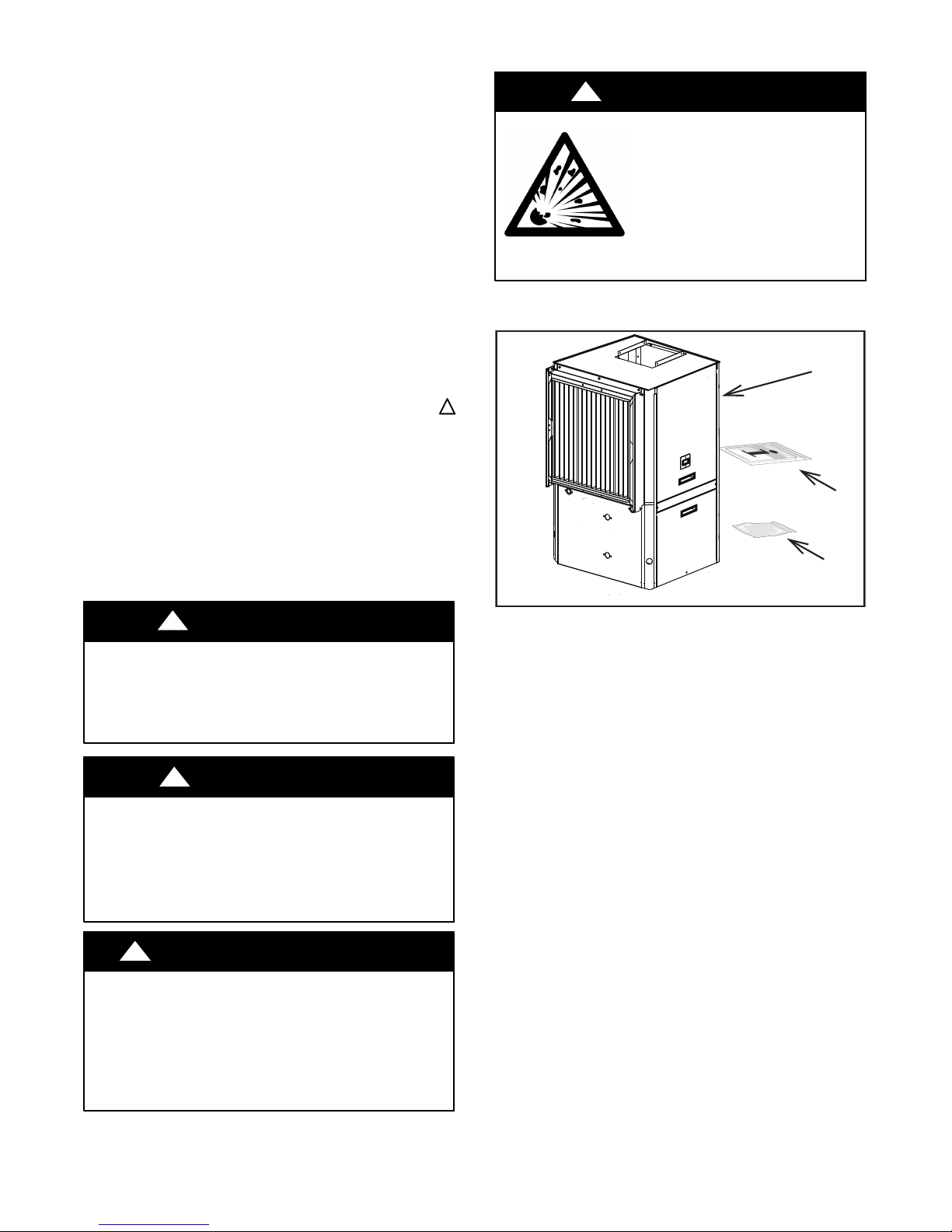
WARNING
Fig. 1 -- Standard Package
A14032
1. GT Series Water-- To Air Heat Pump
2. Installation and Owner’s Manual
3. Hanging Bracket Kit (HZ unit only)
2
Page 3
APPLICATION CONSIDERATIONS
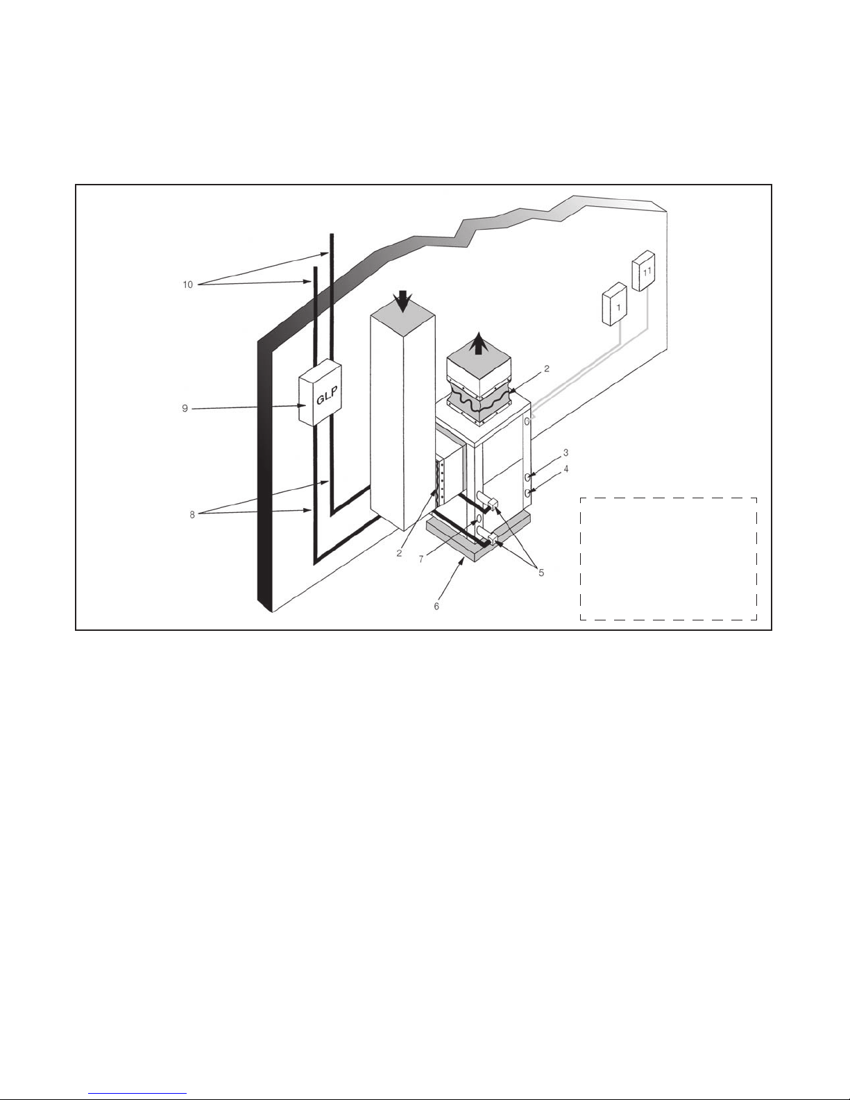
Geothermal Systems
Closed loop and pond applications require specialized design
knowledge. No attempt at these installations should be made unless
the dealer has received specialized training. Anti-- freeze solutions
are utilized when low evaporating conditions are expected to occur.
Refer to the Flow Center installation manuals for more specific
instructions. (See Fig. 2)
(1) Line Voltage Disconnect (unit) (8) Ground Loop Connection Kit
(2) Flex Duct Connection (9) Ground Loop Pumping Package
(3) Low Voltage Control Connection (10) Polyethylene with Insulation
(4) Line Voltage Connection (11) Line Voltage Disconnect (electric heater)
(5) P/T Ports
(6) Vibration Pad
(7) Condensate Drain Connection
Fig. 2 -- Example Geothermal System Setup
Diagram shows typical
installation and is for
illustration purposes
only. Ensure access to
Heat Pump is not
restricted.
A14132
3
Page 4
Well Water Systems
IMPORTANT: Table 1 must be consulted for water quality
requirements when using open loop systems. A water sample must
be obtained and tested, with the results compared to the table.
Scaling potential should be assessed using the pH/Calcium
hardness method. If the pH is <7.5 and the calcium hardness is
l<100 ppm, the potential for scaling is low. For numbers out of the
range listed, a monitoring plan must be implemented due to
probable scaling.
Other potential issues such as iron fouling, corrosion, erosion and
clogging must be considered. Careful attention to water conditions
must be exercised when considering a well water application.
Failure to perform water testing and/or applying a geothermal heat
pump to a water supply that does not fall within the accepted
quality parameters will be considered a mis--application of the unit
and resulting heat exchanger failures will not be covered under
warranty. Where a geothermal system will be used with adverse
water conditions, a suitable plate--frame heat exchanger MUST be
used to isolate the well water from the geothermal unit.
Proper testing is required to assure the well water quality is suitable
for use with water source equipment.
In conditions anticipating moderate scale formation or in brackish
water, a cupronickel heat exchanger is recommended. Copper is
adequate for ground water that is not high in mineral content.
In well water applications, water pressure must always be
maintained in the heat exchanger. This can be accomplished with
either a control valve or a bladder type expansion tank.
When using a single water well to supply both domestic water and
the heat pump, care must be taken to insure that the well can
provide sufficient flow for both.
In well water applications, a slow closing solenoid valve must be
used to prevent water hammer (hammering or stuttering sound in
the pipeline). Solenoid valves should be connected across Y1 and
C1 on the thermostat interface board for all. Make sure that the VA
draw of the valve does not exceed the contact rating of the
thermostat. (See Fig. 3)
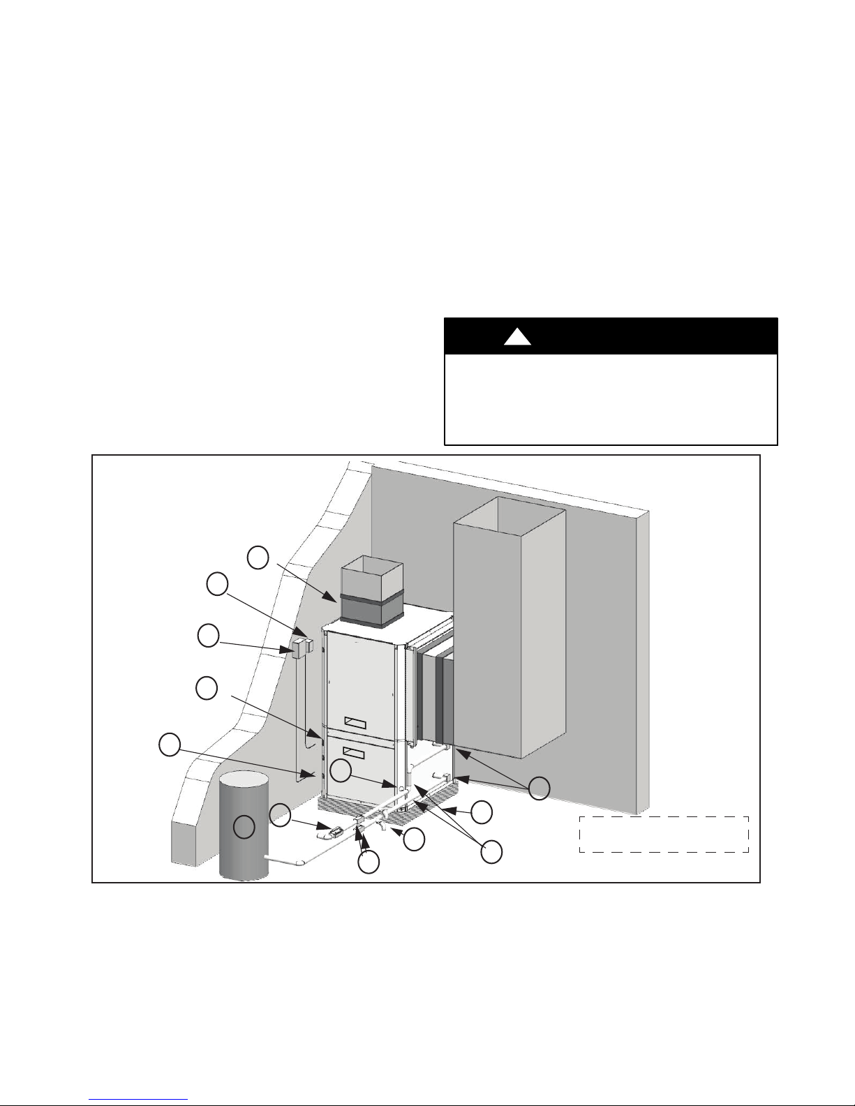
!
UNIT OPERATION HAZARD
Failure to follow this caution may result in equipment
damage or improper operation.
Discharge air configuration change is not possible on Heat
Pumps equipped with Electric Heat Option.
CAUTION
1
13
12
2
11
6
5
9
7
4
(1) Flex Duct Connection (8) Hose Kits (optional)
(2) Low Voltage Control Connection (9) Pressure Tank (optional)
(3) Vibration Pad (10) P/T Ports (optional)
(4) Ball Valves (11) Line Voltage Connection
(5) Solenoid Valve Slow Closing (12) Electric Heater Line Voltage Disconnect
(6) Condensate Drain Connection (13) Unit Line Voltage Disconnect
(7) Drain Valves
Fig. 3 -- Example Well Water System Setup
10
3
Typical Installation shown for
8
illustration purposes only.
A14130
4
Page 5
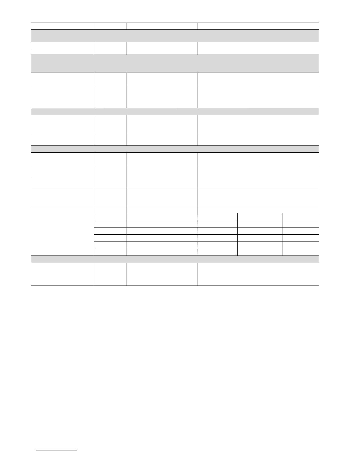
Table 1 – Water Quality Requirements for Open--Loop Geothermal Heat Pump System
Water Quality Parameter HX Material Closed Recirculating Open Loop and Recirculating Well
Scaling Potential - Primary Measurement
Above the given limits, scaling is likely to occur. Scaling indexes should be calculated using the limits below:
pH/Calcium Hardness
Method
Index Limits for Probable Scaling Situations - (Operation outside these limits is not recommended)
Scaling indexes should be calculated at 150°F for direct use and HWG applications, and at 90°F for indirect HX use.
A monitoring plan should be implemented.
Ryznar Stability Index All --
Langelier Saturation Index All --
Iron Fouling
Iron Fe² (Ferrous)
(Bacterial Iron Potential)
Iron Fouling All --
Corrosion Prevention
pH All
Hydrogen Sulfide (H2S) All --
Ammonia ion as hydroxide,
chloride, nitrate and sulfate
compounds
Maximum Chloride Levels
Erosion and Clogging
Particulate Size and
Erosion
NOTES:
S Closed recirculating system is identified by a closed pressurized piping system.
S Recirculating open wells should observe the open recirculating design considerations.
S NR - application not recommended
S "—" No design Maximum
All -- pH <7.5 and Ca Hardness <100ppm
6.0 - 7.5
If > 7.5 minimize steel pipe use
-0.5 to +0.5
If <-0.5 minimize steel pipe use.
Based upon 150°F HWG and Direct well,
84°F Indirect Well HX
<0.2 ppm (Ferrous)
All --
If Fe²* (ferrous) >0.2 ppm with pH 6-8, O2<5 ppm check
for iron bacteria
<0.5 ppm of Oxygen
Above this level deposition will occur
6-8.5
Monitor/treat as needed
Minimize steel pipe below 7 and no open tanks with pH <8
6-8.5
At H S>0.2 ppm, avoid use of copper and copper nickel
piping or HXs. Rotten egg smell appears at 0.5 ppm level.
Copper alloy (bronze or brass) cast components are OK
to <0.5 ppm
All -- <0.5 ppm
Maximum Allowable at Maximum Water Temperature
50°F 75°F 100°F
Copper -- <20 ppm NR NR
cupronickel -- <150 ppm NR NR
304 SS -- <400 ppm <250 ppm <150 ppm
316 SS -- <1000 ppm <550 ppm <375 ppm
Titanium -- >1000 ppm >550 ppm >375 ppm
All
<10 ppm of particles and a
maximum velocity of 1.8 m/s.
Filtered for maximum 841 micron [0.84 mm 20 mesh] size
<10 ppm (<1 ppm "sandfree" for reinjection) of particles
and a maximum velocity of 1.8 m/s. Filtered for maximum
841 micron [0.84 mm. 20 mesh] size. Any particulate that
is not removed can potentially clog components
5
Page 6
INSTALLATION RECOMMENDATIONS
The Water--to-- Air Heat Pumps are designed to operate with
entering fluid temperature between 20_Fto90_F in the heating
mode and between 30_F to 120_F in the cooling mode.
NOTE:50_ minimum Entering Water Temperature (EWT) is
recommended for well water applications with sufficient water
flow to prevent freezing. Antifreeze solution is required for all
closed loop applications or EWT less than 45_. Cooling
Tower/Boiler and Geothermal applications should have sufficient
antifreeze solution to protect against extreme conditions and
equipment failure. Frozen water coils are not covered under
warranty. Other equivalent methods of temperature control are
acceptable.
Check Equipment and Job Site
Moving and Storage
If the equipment is not needed for immediate installation upon its
arrival at the job site, it should be left in its shipping carton and
stored in a clean, dry area. Units must only be stored or moved in
the normal upright position as indicated by the “UP” arrows on
each carton at all times.
!
CAUTION
EQUIPMENT DAMAGE HAZARD
Failure to follow this caution may result in equipment damage.
If unit stacking is required for storage, stack units as follows:
Do not stack units larger than 6 tons!
Vertical units: less than 6 tons, no more than two high.
Horizontals units: less than 6 tons, no more than three high.
Inspect Equipment
Be certain to inspect all cartons or crates on each unit as received at
the job site before signing the freight bill. Verify that all items have
been received and that there are no visible damages; note any
shortages or damages on all copies of the freight bill. In the event
of damage or shortage, remember that the purchaser is responsible
for filing the necessary claims with the carrier. Concealed damages
not discovered until after removing the units from the packaging
must be reported to the carrier within 24 hours of receipt.
Location / Clearance
Locate the unit in an indoor area that allows easy removal of the
filter and access panels, and has enough room for service personnel
to perform maintenance or repair. Provide sufficient room to make
fluid, electrical, and duct connection(s). If the unit is located in a
confined space such as a closet, provisions must be made for return
air to freely enter the face of unit’s air coil. On horizontal units,
allow adequate room below the unit for a condensate drain trap and
do not locate the unit above supply piping.
!
UNIT OPERATION HAZARD
Failure to follow this caution may result in equipment
damage or improper operation.
These units are not approved for outdoor installation;
therefore, they must be installed inside the structure being
conditioned. Do not locate in areas that are subject to
freezing.
!
UNIT DAMAGE AND/OR OPERATION HAZARD
Failure to follow this caution may result in equipment
damage and/or improper equipment operation.
It is extremely important to take the proper precautions to
insure that the heat pump unit is installed in the proper
location and that measures have been taken to prevent
rupturing the water coil due to freezing conditions.
Frozen water coils are not covered under the limited
product warranty.
CAUTION
CAUTION
6
Page 7

CONTROL
J15
GY
RD
TO ECM MOTOR
CFM ADJUST
WHBL ORBR YL
NO
HGRH
TEST
YES
NORM
(+)
(-)
A
BCD
THERMOSTAT
CFM
R C G O Y1 Y2 W1 W2 H C
J14
J17
GN/
GY
PU
BK
YL
WH
BL
ORGN/
BR
BK
J1 J2 J13
P1
GN/
YL
OR
BR
BK
GY
GYPU
RD
L1
P2
BL
WH
P13
GY
GY
RD
PU
L2
BK
WH
BK WH
GN/
LOW VOLT HIGH VOLT
YL
Fig. 4 -- Constant Airflow Motor
J19
P19
A150437
7
Page 8
MOUNTING VERTICAL UNITS
Vertical units should be mounted level on a vibration absorbing
pad slightly larger than the base to minimize vibration transmission
to the building structure. It is not necessary to anchor the unit to the
floor. See Fig. 5.
NOTE: On VT and CF units, the condensate drain pan is
internally sloped. There is no internal P--Trap.
CONDENSATE DRAIN
VIBRATION PAD
FULL SIZE
A14117
Fig. 5 -- Vibration Absorbing Pad
MOUNTING HORIZONTAL UNITS
While horizontal units may be installed on any level surface strong
enough to hold their weight, they are typically suspended above a
ceiling by threaded rods. The manufacturer recommends these be
attached to the unit corners by hanger bracket kits. The rods must
be securely anchored to the ceiling. Refer to the hanging bracket
assembly and installation instructions for details.
IMPORTANT: Horizontal units installed above the ceiling
must conform to all local codes. An auxiliary drain pan, if
required by code, should be at least four inches larger than the
bottom of the heat pump.
Plumbing connected to the heat pump must not come in direct
contact with joists, trusses, walls, etc. Some applications require an
attic floor installation of the horizontal unit. In this case, the unit
should be set in a full size secondary drain pan on top of a
vibration absorbing mesh.
The Secondary drain pan prevents possible condensate overflow or
water leakage damage to the ceiling.
The secondary drain pan is usually placed on a plywood base
isolated from the ceiling joists by additional layers of vibration
absorbing mesh.
In both cases, a 3/4”drain connected to this secondary pan should
be run to an eave at a location that will be noticeable. If the unit is
located in a crawl space, the bottom of the unit must be at least 4”
above grade to prevent flooding of the electrical parts due to heavy
rains.
NOTE: HZ unit condensate drain pan is NOT internally sloped.
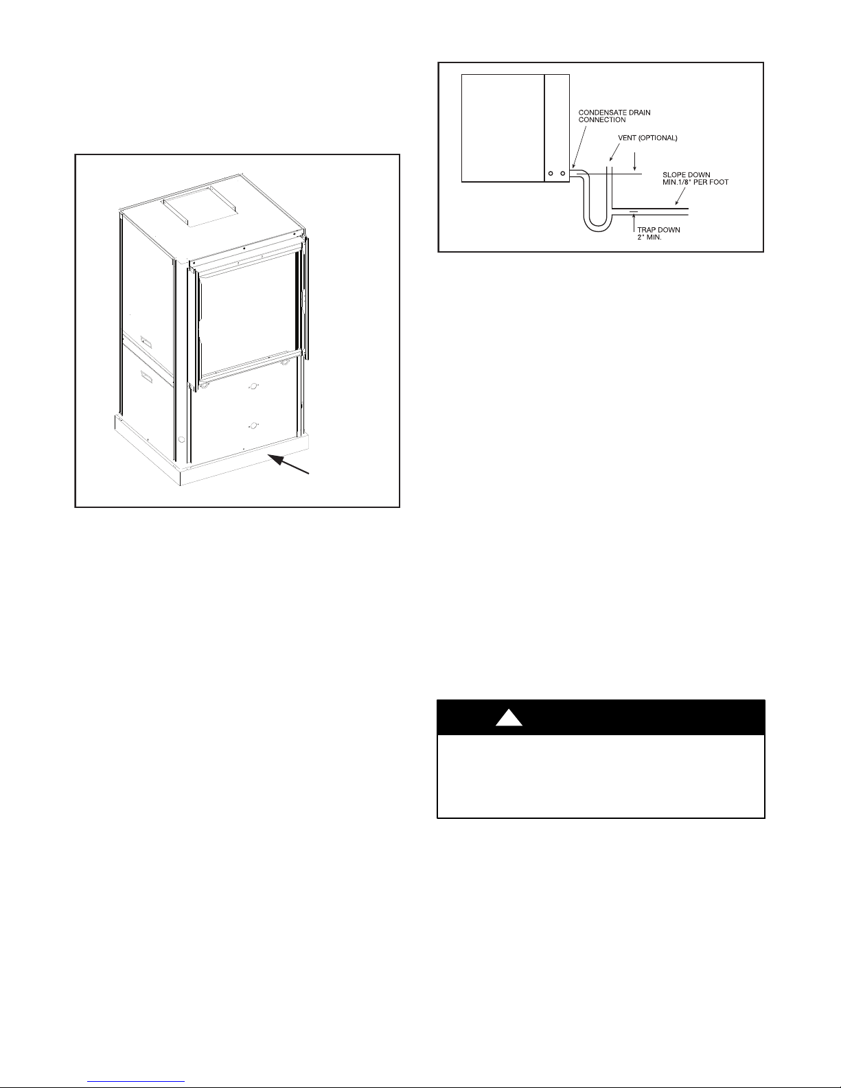
IMPORTANT: Horizontal (HZ) units must be installed pitched
toward the Condensate Drain Connection 1/8” per foot.
Fig. 6 -- Condensate Drain
A drain line must be connected to the heat pump and pitched away
from the unit a minimum of 1/8” per foot to allow the condensate
to flow away from the unit.
IMPORTANT: This connection must be in conformance with
local plumbing codes. A trap must be installed in the
condensate line to insure free condensate flow.
NOTE: HZ heat pump drain pan is not internally sloped.
A vertical air vent is sometimes required to avoid air pockets. The
length of the trap depends on the amount of positive or negative
pressure on the drain pan. A second trap must not be included.
A14118
DUCT SYSTEM
A supply air outlet collar and return air duct flange are provided on
all units to facilitate duct connections.
NOTE: Supply air duct and return air duct flanges are shipped
unfolded with unit.
Fold the duct flange outwards along the perforated line. Refer to
unit Dimensional Drawings for physical dimensions of the collar
and flange.
A flexible connector is recommended for supply and return air duct
connections on metal duct systems. All metal ducting should be
insulated with a minimum of one inch duct insulation to avoid heat
loss or gain and prevent condensate from forming during the
cooling operation.
Application of the unit to uninsulated duct work is not
recommended as the unit’s performance will be adversely affected.
!
UNIT OPERATION HAZARD
Failure to follow this caution may result in improper
equipment operation.
Do not connect discharge ducts directly to the blower
outlet.
The factory provided air filter must be removed when using a filter
back return air grill. The factory filter should be left in place on a
free return system.
If the unit will be installed in a new installation which includes new
duct work, the installation should be designed using current
ASHRAE procedures for duct sizing.
If the unit is to be connected to existing duct work, a check should
be made to assure that the duct system has the capacity to handle
the air required for the unit application.
If the duct system is too small, larger duct work should be installed.
Check for existing leaks and repair.
The duct system and all diffusers should be sized to handle the
designed air flow quietly. To maximize sound attenuation of the
unit blower, the supply and return air plenums should be insulated.
8
CAUTION
Page 9
There should be no direct straight air path through the return air
grille into the heat pump. The return air inlet to the heat pump must
have at least one 90 degree turn away from the space return air
grille. If air noise or excessive air flow are a problem, the blower
speed can be changed to a lower speed to reduce air flow.
PIPING
Supply and return piping must be as large as the unit connections
on the heat pump (larger on long runs).
!
UNIT OPERATION HAZARD
Failure to follow this caution may result in improper
equipment operation.
Never use flexible hoses of a smaller inside diameter than
that of the fluid connections on the unit.
GT units are supplied with either a copper or optional cupronickel
condenser. Copper is adequate for ground water that is not high in
mineral content.
NOTE: Proper testing is recommended to assure the well water
quality is suitable for use with water source equipment. When in
doubt, use cupronickel. See Application Considerations notes on
page 4.
In conditions anticipating moderate scale formation or in brackish
water, a cupronickel heat exchanger is recommended.
Both the supply and discharge water lines will sweat if subjected to
low water temperature. These lines should be insulated to prevent
damage from condensation. All manual flow valves used in the
system must be ball valves. Globe and gate valves must not be
used due to high pressure drop and poor throttling characteristics.
!
EQUIPMENT DAMAGE AND/OR UNIT
OPERATION HAZARD
Failure to follow this caution may result in equipment
damage and/or improper operation.
Never exceed the recommended water flow rates as serious
damage or erosion of the water--to--refrigerant heat
exchanger could occur.
Always check carefully for water leaks and repair appropriately.
Units are equipped with female pipe thread fittings. Consult Unit
Dimensional Drawings.
NOTE: Teflon tape sealer should be used when connecting water
piping connections to the units to insure against leaks and possible
heat exchanger fouling.
NOTE: The unit is shipped with water connection O--rings. A 10
pack of O--rings (part #4026) can be ordered through Replacement
Components Division (RCD).
IMPORTANT: Do not over-- tighten connections.
Flexible hoses should be used between the unit and the rigid
system to avoid possible vibration. Ball valves should be installed
in the supply and return lines for unit isolation and unit water flow
balancing (on open--loop systems).
CAUTION
CAUTION
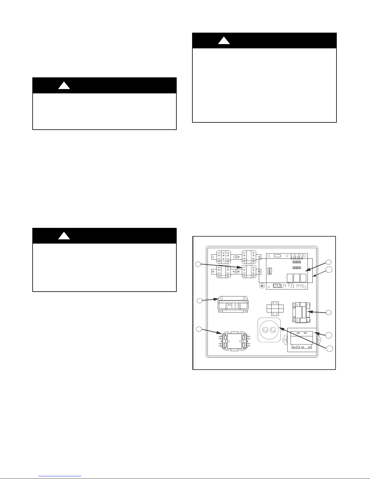
ELECTRICAL
Refer to electrical component box layout. See Fig. 7.
!
UNIT OPERATION HAZARD
Failure to follow this caution may result in equipment
damage and/or improper operation.
S Field wiring must comply w ith local and national
electrical codes.
S Power to the unit must be within the operating voltage
range indicated on the unit nameplate or on the
performance data sheet.
S Operation of unit on improper line voltage or with
excessive phase imbalance will be hazardous to the unit,
constitutes abuse, and may void the warranty.
Properly sized fuses or HACR circuit breakers must be installed for
branch circuit protection. See unit nameplate for maximum fuse or
breaker size.
The unit is provided with a concentric knock--out for attaching
common trade sizes of conduit, route power supply wiring through
this opening.
Always connect the ground lead to the grounding lug provided in
the control box and power leads to the line side of compressor
contactor as indicated on the wiring diagrams.
IMPORTANT: Units supplied with internal electric heat
require two (2) separate power supplies:
1) Unit compressor
2) Electric Heat, blower motor and control circuit.
Refer to the ELECTRIC HEATER PACKAGE OPTION section.
See data plate for minimum circuit ampacities and maximum
fuse/breaker sizing.
3
2
1
(1) Compressor Contactor (5) Auxiliary Pump Relay (Option)
(2) Comfort Alert Module (6) Transformer
(3) Second Stage Relay (7) Capacitor
(4) Unit Protection Module (UPM) (8) ECM Module
Fig. 7 -- Electrical Component Box Layout
CAUTION
4
8
5
6
7
A14119
-- mounts on E-- box cover
9
Page 10
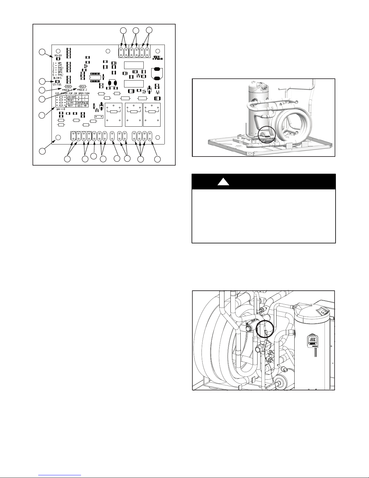
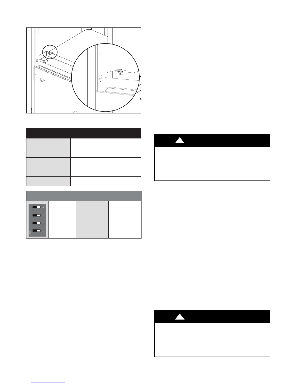
Safety Devices and UPM Controller
1
2
3
4
5
S Water side freeze protection sensor, mounted close to condensing
water coil, monitors refrigerant temperature between condensing
11
1213
water coil and thermal expansion valve. If temperature drops
below or remains at freeze limit trip for 30 seconds, the controller
will shut down the compressor and enter into a soft lockout
condition.
The default freeze limit trip is 26_F, however this can be changed
to 15_F by cutting the R30 or Freeze1 resistor located on top of
DIP switch SW1 (Refer to Fig. 8, item (3) for resistor location),
RefertoFig.9forsensorlocation.
17
6
(1) Board Power Indicator (10) Compressor Contact Output
(2) UPM Status LED Indicator (11) High Pressure Switch Connection
(3) Water Coil Freeze Protection
Temperature Selection [R30]
(4) Air Coil Freeze Protection
Temperature Selection
(5) UPM Board Settings (14) 24VAC Power Common
(6) Water Coil Freeze Connection (15) Condensate Overflow Sensor
(7) Air Coil Freeze Connection (16) Dry Contact
(8) LCD Unit Display Connection (17) UPM Ground Standoff
(9) 24VAC Power Input
15
7
8
14
(12) Call for Compressor Y1
(13) Low Pressure Switch Connection
16
9
10
A14120
Fig. 8 -- Safety Device and UPM Controller
NOTES:
1. If the unit is being connected to a thermostat with a malfunction light, this connection is made at the unit malfunction output or relay. Refer to Fig. 8.
2. If the thermostat is provided with a malfunction light powered off of the common (C) side of the transformer, a
jumper between “R” and “COM” terminal of “ALR” contacts must be made.
3. If the thermostat is provided with a malfunction light powered off of the hot (R) side of the transformer, then the thermostat malfunction light connection should be connected
directly to the (ALR) contact on the unit’s UPM board.
Each unit is factory provided with a Unit Protection Module
(UPM) that controls the compressor operation and monitors the
safety controls that protect the unit.
Safety controls include the following:
S High pressure switch located in the refrigerant discharge line and
wired across the HPC terminals on the UPM.
S Low pressure switch located in the unit refrigerant suction line
and wired across terminals LPC1 and LPC2 on the UPM.
NOTE: UPM Board Dry Contacts are normally open (NO)
Fig. 9 -- Freeze Protection Sensor Location
A14121
!
CAUTION
UNIT DAMAGE AND/OR OPERATION HAZARD
Failure to follow this caution may result in unit damage
and/or improper equipment operation.
If unit is employing a fresh water system (no anti--freeze
protection), it is extremely important to have the Freeze1
R30 resistor set to 26_F in order to shut down the unit at
the appropriate leaving water temperature and protect your
heat pump from freezing if a freeze sensor is included.
S Evaporator freeze protection sensor, mounted after the thermal
expansion device and the evaporator, monitors refrigerant
temperature between the evaporator coil and thermal expansion
valve. If temperature drops below or remains at freeze limit trip
for 30 seconds, the controller will shut down the compressor and
enter into a soft lockout condition. The default freeze limit trip is
26_F. See Fig. 10.
Fig. 10 -- Evaporator Freeze Protection Sensor Location
A14122
10
Page 11
S The condensate overflow protection sensor is located in the drain
pan of the unit and connected to the ”COND” terminal on the
UPM board. See Fig. 11.
A14123
Fig. 11 -- Condensate Overflow Protection Sensor Location
UPM Board Factory Default Settings
S MALFUNCTION OUTPUT: Alarm output is Normally Open
(NO) dry contact. If pulse is selected the alarm output will be
pulsed. The fault output will depend on the dip switch setting for
”ALARM”. If it is set to ”CONT”, a continuous signal will be
produced to indicate a fault has occurred and the unit requires
inspection to determine the type of fault. If it is set to ”PULSE”, a
pulse signal is produced and a fault code is detected by a remote
device indicating the fault. See L.E.D Fault Indication below for
blink code explanation. The remote device must have a
malfunction detection capability when the UPM board is set to
”PULSE”.
NOTE: If 24 VAC output is needed, R must be wired to
ALR--COM terminal; 24 VAC will be available on the ALR--OUT
terminal when the unit is in the alarm condition.
S DISPLAY OUTPUT: The Display output is a pulse output
connected to the Unit Diagnostic Display (UDD) and it pulses
24VAC when the unit is in an lockout alarm condition.
S UPM TEST MODE: UPM test mode will allow all time--delay
settings to be reduced to 10 seconds for troubleshooting and
verification of unit operation. Reset unit to TEST mode: NO
when test is completed. During UPM test mode, the UPM LED
will flash a FREEZE SENSOR 6 flash code. Test mode will
automatically defeat after approximately 5 minutes with no LED
flash and normal delays.
TEMP
LOCKOUT
RESET
ALARM
TEST
UPM DIP SWITCH DEFAULT POSITION
lockout 4
reset
alarm
test
The UPM Board includes the following features:
S ANTI-- S HORT CYCLE TIMER: 5 minute delay on break
timer to prevent compressor short cycling.
S RANDOM START: Each controller has an unique random start
delay ranging from 270 to 300 seconds on initial power up to
reduce the chance of multiple unit simultaneously starting at the
same time after power up or after a power interruption, thus
avoiding creating large electrical spike.
S LOW PRESSURE BYPASS TIMER:Ifthecompressoris
running and the low pressure switch opens, the controller will
keep the compressor ON for 120 seconds. After 2 minutes if the
low pressure switch remains open, the controllers will shut down
the compressor and enter a soft lockout. The compressor will not
be energized until the low pressure switch closes and the
anti--short cycle time delay expires. If the low pressure switch
opens 2--4 times in 1 hour, the unit will enter a hard lockout. In
order to exit hard lockoutpower to the unit would need to bereset.
S BROWNOUT / SURGE / POWER INTERRUPTION
PROTECTION: The brownout protection in the UPM board
will shut does the compressor if the incoming power falls below
18 VAC. The compressor will remain OFF until the voltage is
above 18 VAC and ANTI--SHORT CYCLE TIMER (300
seconds) times out. The unit will not go into a hard lockout.
30°F
2
Y
PULSE
NO
2
RY
Cont
yes
pulse
no
!
UNIT DAMAGE AND/OR OPERATION HAZARD
Failure to follow this caution may result in unit damage
and/or improper equipment operation.
Operation of unit in test mode can lead to accelerated wear
and premature failure of components. The ”TEST” switch
must be set back to ”NO” after troubleshooting/ servicing.
S FREEZE SENSOR: The default setting for the freeze limit trip is
26_F (sensor number 1); however this can be changed to 15_Fby
cutting the R30 resistor located on top of the DIP switch SW1.
Since freeze sensor 2 is dedicated to monitor the evaporator coil, it
is recommended to leave the factory default setting on the board.
The UPM controller will constantly monitor the refrigerant
temperature with the sensor mounted close to the condensing
water coil between the thermal expansion valve and water coil. If
temperature drops below or remains at the freeze limit trip for 30
seconds, the controller will shut the compressor down and enter
into a soft lockout condition. Both the status LED and the Alarm
contact will be active.
The LED will flash the code associated with this alarm condition
three (3) times. If this alarm occurs 2 times (or 4 if Dip switch is set
to 4) within an hour, the UPM controller will enter into a hard
lockout condition. It will constantly monitor the refrigerant
temperature with the sensor mounted close to the evaporator
between the thermal expansion valve and evaporator coil as
shown in Fig. 10.
If temperature drops below or remains at the freeze limit trip for
30 seconds, the controller will shut the compressor down and
enter into a soft lockout condition. Both the status LED and the
alarm cont act will be activ e. T he LE D will flash the cod e
associated with this alarm condition six (6) times. If this alarm
occurs 2 times (or 4 if Dip switch is set to 4) within an hour, the
controller will enter into a hard lockout condition.
!
UNIT DAMAGE AND/OR OPERATION HAZARD
Failure to follow this caution may result in unit damage
and/or improper equipment operation.
Freeze sensor will not guard against the loss of water. A
flow switch is recommended to prevent the unit from
running if water flow is lost or reduced.
CAUTION
CAUTION
11
Page 12
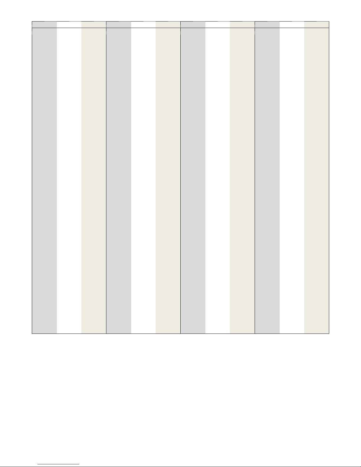
Table 2 – 10K Temperature Sensor Resistance Table
°C °F OHM °C °F OHM °C °F OHM °C °F OHM
--- 55 --- 67 963,800 --- 9 16 52,410 37 99 6,015 83 181 1,141
--- 54 --- 65 895,300 --- 8 18 49,660 38 100 5,774 84 183 1,105
--- 53 --- 63 832,100 --- 7 19 47,070 39 102 5,545 85 185 1,071
--- 52 --- 62 776,800 --- 6 21 44,630 40 104 5,326 86 187 1,038
--- 51 --- 60 719,900 --- 5 23 42,330 41 106 5,116 87 189 1,006
--- 50 --- 58 670,200 --- 4 25 40,160 42 108 4,916 88 190 975
--- 49 --- 56 624,200 --- 3 27 38,120 43 109 4,725 89 192 945
--- 48 --- 54 581,600 --- 2 28 36,190 44 111 4,542 90 194 916
--- 47 --- 53 542,200 --- 1 30 34,370 45 113 4,368 91 196 889
--- 46 --- 51 505,800 0 32 32,650 46 115 4,201 92 198 862
--- 45 --- 49 472,000 1 34 31,030 47 117 4,041 93 199 836
--- 44 --- 47 440,700 2 36 29,500 48 118 3,888 94 201 811
--- 43 --- 45 411,600 3 37 28,050 49 120 3,742 95 203 787
--- 42 --- 44 384,700 4 39 26,690 50 122 3,602 96 205 764
--- 41 --- 42 359,700 5 41 24,400 51 124 3,468 97 207 741
--- 40 --- 40 336,500 6 43 24,170 52 126 3,339 98 208 720
--- 39 --- 38 314,900 7 45 23,020 53 127 3,216 99 210 699
--- 38 --- 36 294,900 8 46 21,920 54 129 3,099 100 212 679
--- 37 --- 35 276,200 9 48 20,890 55 131 2,986 101 214 659
--- 36 --- 33 258,800 10 50 19,900 56 133 2,878 102 216 640
--- 35 --- 31 242,700 11 52 18,970 57 135 2,774 103 217 622
--- 34 --- 29 227,600 12 54 18,090 58 136 2,674 104 219 604
--- 33 --- 27 213,600 13 55 17,260 59 138 2,579 105 221 587
--- 32 --- 26 200,500 14 57 16,470 60 140 2,488 106 223 571
--- 31 --- 24 188,300 15 59 15,710 61 142 2,400 107 225 555
--- 30 --- 22 177,000 16 61 15,000 62 144 2,316 108 226 539
--- 29 --- 20 166,400 17 63 14,330 63 145 2,235 109 228 525
--- 28 --- 18 156,400 18 64 13,380 64 147 2,157 110 230 510
--- 27 --- 17 147,200 19 66 13,070 65 149 2,083 111 232 496
--- 26 --- 15 138,500 20 68 12,490 66 151 2,011 112 234 483
--- 25 --- 13 130,400 21 70 11,940 67 153 1,942 113 235 470
--- 24 --- 11 122,800 22 72 11,420 68 154 1,876 114 237 457
--- 23 --- 9 115,800 23 73 10,920 69 156 1,813 115 239 445
--- 22 --- 8 109,100 24 75 10,450 70 158 1,752 116 241 433
--- 21 --- 6 102,900 25 77 10,000 71 160 1,693 117 243 422
--- 20 --- 4 97,080 26 79 9,573 72 162 1,637 118 244 411
--- 19 --- 2 91,620 27 81 9,166 73 163 1,583 119 246 400
--- 18 0 86,500 28 82 8,778 74 165 1,531 120 248 389
--- 17 1 81,700 29 84 8,409 75 167 1,480 121 250 379
--- 16 3 77,190 30 86 8,057 76 169 1,432 122 252 370
--- 15 5 72,960 31 88 7,722 77 171 1,386 123 253 360
--- 14 7 68,980 32 90 7,402 78 172 1,341 124 255 351
--- 13 9 65,250 33 91 7,098 79 174 1,298 125 257 342
--- 12 10 61,740 34 93 6,808 80 176 1,256 126 259 333
--- 11 12 58,440 35 95 6,531 81 178 1,216 127 261 325
--- 10 14 55,330 36 97 6,267 82 180 1,178 128 262 317
S HIGH PRESSURE SWITCH: The high pressure switch safety
is designed to shut down the compressor if it exceeds limits. Cut
in 420 +/-- 15 psig and cut out 600 +/-- psig.
S LOW PRESSURE SWITCH: The low pressure switch safety is
designed to shut down thecompressor of loss of charge. Cut in 60
+/-- 15 psig and cut out 40 +/-- psig.
S INTELLIGENT RESET: If a fault condition is initiated, the 5
minute delay on break time period is initiated and the unit will
restart after these delays expire. During this period the fault LED
will indicate the cause of the fault. If the fault condition still exists
or occurs 2 or 4 times (depending on 2 or 4 setting for Lockout dip
switch) before 60 minutes, the unit will go into a hard lockout and
requires a manual lockout reset.
A single condensateoverflow fault will cause the unit to go into a
hard lockout immediately,and willrequire a manual lockout reset.
S LOCKOUT RESET: A hard lockout can be reset by turning the
unit thermostat off and then back on when the “RESET” dip
switch is set to “Y” or by shutting off unit power at the circuit
breaker when the “RESET” dip switch is set to “R”.
NOTES: The blower motor will remain active during a lockout
condition.
S ECM TEST MODE: ECM test mode is to override the motor to
constant torque mode for motor troubleshooting. If the motor
runs in ECM test mode, the module and motor are good. To
engagein ECM test mode, only one switch canbe selected. Select
TEST ON and all others OFF. Reset the board to NORM ON and
TEST OFF when test is complete.
If the unit remains in test mode for normal operation, the system
will not run different CFMs based on thermostat call such as Y1,
Y2 or dehumidify. It may also experience problems with
nuisance strip during electric heat operation.
There is no way to check CFM based on number of blinks if the
board is set to test mode.
12
Page 13
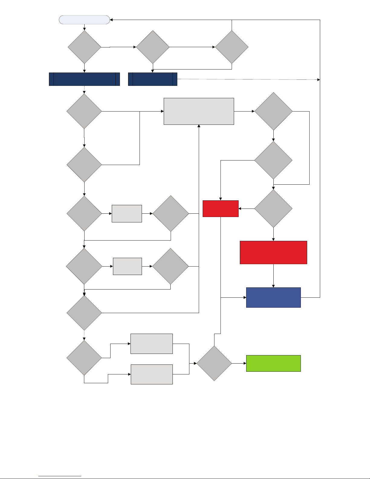
START
Y1 = ON
NO
RESET ON
Y
NO
RESET ON R
YES
R = 24VAC
YES
POWER/ SWITCHES/SENSOR
STATUS CHECK
V > 18VAC
NO
YES
HPC =
CLOSED
NO
YES
LPC
=CLOSED
NO
YES
START
TIMER
YES
CLEAR FAULTS
TIME > 120
NO
BLINK CODE ON STATUS LED
SOFT LOCKOUT
RECORD ALARM
START COUNTER (IF APPLICABLE)
LOCKOUT CAN BE SET
TO 4 VIA DIP SWITCH
BLINK CODE
ON STATUS LED
SEC
YES
NO
NO
NO
COUNTER
NEEDED?
YES
COUNT = 2
OR
COUNT = 4
YES
HARD
LOCKOUT?
YES
NO
FRZ >TEMP
LIMIT
YES
CON > 0
YES
INITIAL
POWER UP
YES
NO
NO
NO
BLINK CODE ON STATUS LED
START
TIMER
TIME > 30
SEC
YES
NO
START
ANTI SHORT CYCLE
START
RANDOM START UP
NO
T > ASC OR
RS SEC
YES
CC
Fig. 12 -- UPM Sequence of Operation (SOO) Flow Chart
DISPLAY OUTPUT = PULSE
ALR OUTPUT = ON/PULSE
CC OUTPUT = OFF
CC OUTPUT = ON
A14129
13
Page 14
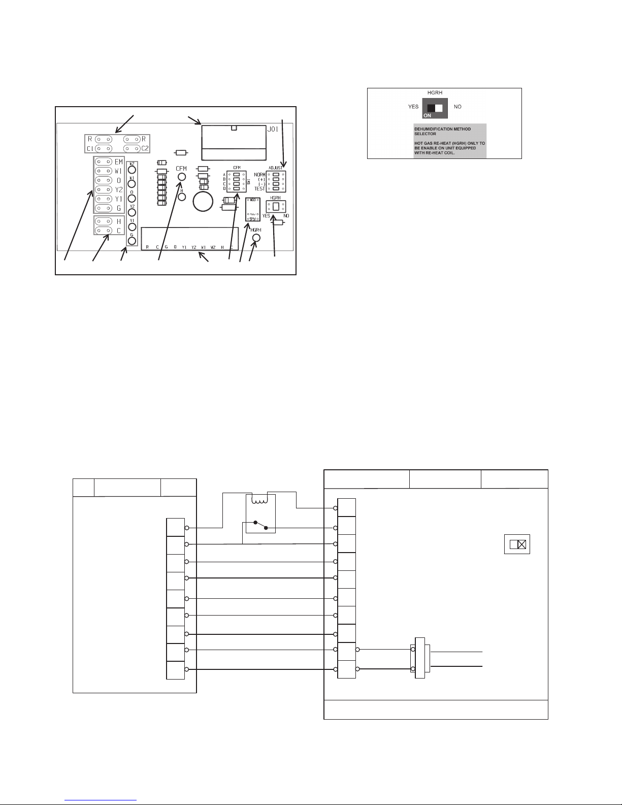
ECM INTERFACE BOARD
Refer to Fig. 7, item (12) for ECM interface board location. In
addition to providing a connecting point for thermostat wiring, the
interface board also translates thermostat inputs into control
commands for the Electronic Commutated Motor (ECM) DC fan
motor and provides thermostat signals to unit’s UPM board. The
thermostat connections and their functions are as follows:
10
1
3
Dehumidification Mode
Position the HGRH DIP switch in the “NO” (OFF) position.
When the switch is in this position, upon a dehumidification call,
the unit will operate at a lower speed to increase dehumidification
while cooling. See Fig. 14.
8
9
(1) Motor Harness Plug (7) Thermostat Input Status Indication
(2) Blower CFM Adjustment (8) Reheat Digital Outputs
(3) Motor Settings (9) Thermostat Outputs
(4) Dehumidification Indication (10) 24 VAC
(5) Thermostat Contact Inputs (11) Dehumidification Method Selector
(6) CFM Count Indicator
27
5
11
46
A14124
Fig. 13 -- ECM Interface Board
NOTE: CFM LED indication is an approximation. Utilize
conventional Test and Balance equipment for accurate airflow
measurement.
S CFM count indicator (see Fig. 13, item 6) blinks to indicate
approximate airflow in CFM and may flicker when the unit is off.
S Each blink of the LED represent approximately 100 CFM of air
delivery so if the LED blinks 12 times, pauses, blinks 12 times,
etc. the blower is delivering approximately 1200 CFM.
Fig. 14 -- Dehumidification Method Selector
A14126
Thermostat Outputs
Dry Contact Left side terminal strip in the stat, D1, D2
YI First Stage Compressor Cool
Y/Y2 Second Stage Compressor Cool
W1 Auxiliary Electric Heat
(runs in conjunction with compressor)
W2/E Emergency Heat (electric heat only)
O Reversing Valve (energized in cooling)
GFan
R Transformer 24 VAC Hot
C Transformer 24 VAC Common
NOTE: When unit is used with Carrier and Bryant thermostats
with Relative Humidity Control (Carrier Edge TP--PRH or
TP--NRH / Bryant Preferred T6-- PRH or T6--NRH), the unit’s
dehumidification mode is in reverse logic and will not activate
dehum unless a relay, as shown in Fig. 15, is used. A simplified
explanation of the reverse logic follows.
RH ECM
Stat Logic: Board Logic:
No Dehum Demand: Dh -- energized Dh--not energized
Dehum Demand: Dh -- de--energized Dh -- energized
THERMOSTAT
24V OUTPUTS
DE-H UMID IFICATION CA LL
COOLING STAGE 1
COOLING STAGE 2
HEATING STAGE 1
HEATING STAGE 2
SWITCH OVER VALVE
BLOWER
24VAC (HOT)
24VAC (COMMON)
Fig. 15 -- Cool to Dehumidify Application for Thermostats with Dehumidification
Dry
Contact
Y1
Y2
W1
W2/E
O/B
G
R
C
RELAY
C
H
HUMIDISTAT
Y1
COOLING STAGE 1
Y2
COOLING STAGE 2
W1
HEATING STAGE 1
W2
HEATING STAGE 2
O
REVERSING VALVE
G
BLOWER
R
C
DHR – DEHUMIDIFICATION RELAY
FIELD INST ALLE D
CAV42
(Not required for Cor / Housewise thermostats)
ECM CONTROLLER INTERFACE
24V INPUTS
YES N O
STLOV ENIL
EX: 230VAC
LOW VOLTAGE CLASS II WIRING – 18AWG
HGRH
A150487
14
Page 15

Dehumidification Configuration
For Cor/Housewise Thermostats
(Carrier: TP--WEM01 / Bryant: T6--WEM01)
These thermostats allow dehum operation without need for a relay
if the dehum active status is selected to “Closed”
NOTE: Super--dehum mode is not available in screen options
when DEHUM ACTIVE status is selected and is not recommended
if using DEHUM ACTIVE status of “Open” and a relay. Airflows
programmed in the control boards will not provide super dehum
operation.
During the guided setup process, configure the thermostat with a
dehumidifier on the output that is powered by the thermostat.
Following is an example of the thermostat display screen during
guided equipment setup process.
By default, the thermostat will configure the dehumidifier output
(ACC+) as ACTIVE OPEN. For geothermal heat pumps, this
configuration setting will need to be changed to ACTIVE
CLOSED.
The setting can be changed on the thermostat by going to:
Menu > Service (hold for 10 sec) > Installation Settings >
Equipment Setup > Accessory > Dehum Active
THERMOSTAT
24V OUTPUTS
DE-HU MIDIFICAT ION CALL
COOLING STAGE 1
COOLING STAGE 2
HEATING STAGE 1
HEATING STAGE 2
SWITCH OVER VALVE
BLOWER
24VAC (HOT)
24VAC (COMMON)
Super Dehumidification
Super Dehumidification should NOT be used with geothermal heat
pumps.
Cor/Housewise with Field Installed Relay
If motor intermittently runs with no call, refer to Fig 16.
NOTE: In thermostats with triacs, such as the Core or Housewise,
there is potential for the triac to bleed slight voltage to the blower
circuit. In some cases it is low enough to be unnoticeable but in
rare occasions the voltage trickle could be enough (typically >8.5
volts) to bump over the blower intermittently with no G call. If
this occurs, it is recommended to add a normally open relay in the
blower circuit. Refer to Fig 16.
ECM CONTROLLER INTERFACE
24V INPUTS
C
H
H
Y1
Y2
W1
W2/E
O/B
G
R
C
RELAY
HUMIDISTAT
Y1
COOLING STAGE 1
Y2
COOLING STAGE 2
W1
HEATING STAGE 1
W2
HEATING STAGE 2
O
REVERSING VALVE
G
BLOWER
R
C
HGRH
YES NO
CAV42
EX: 230VAC
STLOV ENIL
Fig. 16 -- Wiring for Cor / Housewise Adjusted for Geothermal Application
LOW VOLTAGE CLASS II WIRING – 18AWG
DHR – DEHUMIDIFICATION RELAY
FIELD IN STALLED
15
A150489
Page 16

START
G = ON
NO
YES
ADJUST / DELAY STATUS DIP
SWITCH CHECK
ECM CONTROL BOARD DE-HUMIDIFICATION OPTIONS
SEQUENCE OF OPERATION
MOTOR
RUNS WITH
ANY
NO
SIGNAL
YES
ADJ =
NORMAL
YES
DELAY = A
YES
HGRH SW =
YES
YES
J01-10 = 24VAC
P13-H = TB01-H
Y1=ON
YES
NO
ADJ = + ADJ = -
YES
DELAY = B DELAY = C
NO
YES
NO
IMPORTANT:
WHEN HGRH DIP SWITCH IS
SET TO “YES” THE BK LINE
WILL BE ENERGIZED ALL THE
TIME REGARDLESS OF TB1-H
SIGNAL
FAN ONLY (K
NO
NO
NO
IMPORTANT:
“ADJ +” AND “ADJ – “ , INCREASE
OR DECREASE APROX 15% OF
NO
NOMINAL CFM VALUE.
DELAY A,B,C OR D SELECT CFM
PROFILE FACTORY DEFAUL IS “A”
NO
BLOWER MOTOR = OFF
YES
YES
NO
NO
ADJ = TEST
YES
DELAY = C
YES
COOL TO DE-HUMIDIFY
P13-H = 0
TB01-H = ON
YES
NO
IMPORTANT:
WHEN HGRH DIP SWITCH IS SET TO
FAN
)CFM
ENABLE DEHUMIDIFY ON MOTOR
DE-ENERGIZE J01-10 (BK10 =0)
WHEN SENSING H SIGNAL FROM
TSTAT
“NO” THE BK LINE WILL BE
ENERGIZED ALL THE TIME AND
ONLY DE-ENERGIZED WHEN TB01-H
SENSES 24 VAC.
BLOWER RUNS RUNS IN
PART LOAD CFM
Y1 PERCENTAGE
NO
Y2 = ON
YES
BLOWER RUNS RUNS IN
FULL LOAD CFM
Y2 PERCENTAGE
TB01-H
NO
YES
W1 OR W2
=ON
NO
YES
FAN NOMINAL CFM
RUN MOTOR IN NOMINAL CFM
ENERGIZE H OUTPUT
P13-H = ON
Fig. 17 -- ECM Sequence of Operation
16
Y1=ON
YES
BLOWER RUNS RUNS IN
PART LOAD CFM
Y1 PERCENTAGE TIMES
THE DE-HUM PERCENT
Y2 = ON
NO
YES
BLOWER RUNS RUNS IN
PART LOAD CFM
Y2 PERCENTAGE TIMES
THE DE-HUM PERCENT
NO
Page 17

Airflow Selector
The airflow selector (see Fig. 13, items 2 and 3 and Fig. 18) allows
airflow adjustment to meet application requirements and to ease
troubleshooting.
NOTE: Only one switch can be enabled at a time. Refer to Fig. 18
for each airflow setting.
S CFM Selector must remain with only “A” being enabled.
S ADJUST Selector can be adjusted to NOM, (+), (--), or TEST.
NOM, (+) and (--) can be adjusted as needed by application. TEST
is used for troubleshooting to override unit airflow to 100%.
Comfort Alert Diagnostics Module (CADM)
The Comfort Alert Diagnostics Module (CADM) is a breakthrough
innovation for troubleshooting heat pump system failures (see Fig.
19).
CFM PROFILE SELECTOR
PROFILES PROGRAMMED IN THE
MOTOR REFER TO AIRFLOW PROFILE
TABLES IN INSTALLATION MANUAL.
FACTORY DEFAULT IS SET TO “A”.
ALL TABLES REFER TO “A” PROGRAM
ONLY.
AIRFLOW PERCENT SELECTOR
ONLY ONE SWITCH IS TO BE ENABLED
AT A TIME.
PERCENTAGES PROGRAMMED IN THE
MOTOR REFER TO AIRFLOW TABLE IN
INSTALLATION MANUAL.
TYPICALLY, “+” = 15% INCREASE IN
AIRFLOW
A150444
Fig. 18 -- Airflow Selector
!
CAUTION
UNIT DAMAGE AND/OR OPERATION HAZARD
Failure to follow this caution may result in unit damage
and/or improper equipment operation.
Do not set the ADJUST DIP switch to the (--) setting when
electric heaters are installed. Doing so may cause the
heaters to cycle on their thermal overload switches,
potentially shortening the life of the switches.
!
CAUTION
UNIT DAMAGE AND/OR OPERATION HAZARD
Failure to follow this caution may result in unit damage
and/or improper equipment operation.
Always disconnect power before changing DIP switch
positions on the interface board and reset the unit
afterward.
Constant Airflow Motor
The Constant Airflow Motor is an Electronic Commutated Motor
(ECM) that provides a constant air flow over a wide range of
external static pressures while optimizing the power consumption
of the motor. This option allows the unit to have different air flow
settings depending on the mode that the unit is operating; i.e
heating, cooling, fan only, hot gas reheat, etc. Refer to the ECM
Interface Board section in this document for more information.
Pump Relay
The factory installed pump relay can be used to energize a supply
pump or solenoid valve when there is a call for compressor
operation. This relay can be used to switch either high or low
voltage power.
Fig. 19 -- Comfort Alert Diagnostics Module (CADM)
A14127
By monitoring and analyzing data from the compressor and the
thermostat demand, the module can accurately detect the cause of
electrical and system related failures without any sensors. A
flashing LED indicator communicates the ALERT code and guides
the service technician more quickly and accurately to the root cause
of a problem.
IMPORTANT: This module does not provide safety protection!
The Comfort Alert Diagnostics Module is a monitoring device
only and cannot shut down the compressor directly.
When an abnormal system condition occurs, the CADM displays
the appropriate ALERT and/or TRIP LED. The yellow ALERT
LED will flash a number of times consecutively, pause and then
repeat the process. To identify a Flash Code number, count the
number of consecutive flashes. Every time the module powers up,
the last ALERT Flash Code that occurred prior to shut down is
displayed for one minute.
Comfort Alert Codes
The comfort alert codes are marked on the back of the device for
field service.
GREEN LED -- 24VAC Power
YELLOW LED -- Flash Code
1. Long run time
2. System pressure trip
3. Short cycling
4. Locked rotor
5. Open circuit
6. Open start circuit
7. Open run circuit
8. Welded contactor
9. Low voltage
RED LED (solid) -- Protector open or no compressor power
Reset the codes y breaking 24VAC to the module.
17
Page 18

FACTORY INSTALLED FEATURES
A number of factory installed options are available on the GT
Series of Heat Pumps. The following details the purpose, function
and components of each option.
Smart Start Assist
The Smart Start Assist (SSA) is designed to reduce the in--rush
draw during single--phase scroll start--up. The kit contains two
main parts (shown in Fig. 20), the mounting plate and the SSA
component. The kit is installed on top of the unit’s electrical box.
The SSA reduces compressor starting currents, limiting the peak
energy demand. SSA has a dedicated algorithm and built--in
current limit settings specifically for scroll compressor starting.
The designed soft start algorithm slowly ramps the in--rush current
which results in the elimination of light flickering, reduction in
voltage disturbances and increased compressor lifetime. The SSA
can lock out the unit and incorporates its own 5 min. time delay,
Refer to Fig. 21, Mode of Operation. This 5 minute anti--cycle
delay that could possibly hold unit off even if the UPM test switch
is activated in attempt to override the UPM 5 min delay.
De--energizing the SSA is the only way to override its built in time
delay (refer to unit wiring diagram).
Optional for
remote alarm
Smart Start
Assist
Mounting Plate
A150464
Fig. 20 -- Smart Start Assist
1. The Smart Start Assist has 2 indication LEDs on board. The green LED
indicates the status fo the on-board power supply while the red LED indicates an alarm condition or the recovery time between starts
2. Once the mains voltage is present , the green LED will be fully ON. In case
the mains voltage is less than the stated pickup volta ge alarm value, the
green LED will be flashing. In case the mains voltage is higher than the
stated pickup volt age and the green LED is flashing, this may indicate that
the on-board power supply is faulty. (Power Supply Alarm)
3. Upon closing K1, the Smart Start Assist will start ramping for duration of
<1 second provided that the minimum time from stop to start is respected. When opening t he K1, the Smart St art Assist will stop without any
ramp down.
4. In case of an under-voltage, the Smart St art Assist will shut do wn a nd the
red LED will flash 2 times as long as the under-voltage is present. Once
the mains voltage is restored, the red LED will continue flashing for 5 minutes (6 minute s for HP versions). Following these 5 minutes, the Smart
Start Assist will start ramping function in the case k1 is closed. The device
can be reset at any time by removing power on L1-N connection. When
the power is reapplied, the soft starter will start ramping up as soon as K1
is closed provided that the minimum time between starts and the minimumtimefromstoptostartarerespected.
5. If an over--- current (>80A for 1 second) is sensed, the Smart Start Assist
will shut down and the red LED will flash 3 time s indica ting an over ---current situation. This continues for 5 minutes. In the case tha t the over---current is still present at the second attempt, user intervention is required to
meet the controller by cycling power for the device to operate again as
this implies that there are problems in the system.
Manual resets may be necessary if consecutive flash codes:
1
2-- Over current
4-- Relay Protection
5-- Incomplete Ramp
Fig. 21 -- Mode of Operation
6. A detection circuitry provides protection in case of a faulty starting capacitor EMR. In such a situatio n, the red LED will flash 4 times for 5 minutes.
Smart Start Assist will check the status of the starting capacitor EMR before attempting a ramping function (in the case K1 is closed). If, at the
second attempt, the starting capacitor EMR is found to be faulty, user intervention is required to reset the controller by cycle power for the device.
7. Inthecaseofincompleterampingofthesoftstarter,theredLEDwillflash
5 t imes. The flashing will be indicated by the red LED for 5 minutes. If,
after the second attempt, there is another incomplete ramp alarm, user
intervention is required to reset the controller.
8. During recovery from under ---voltage, over---current and incomplete ramp
alarms, the red LED will flash twice the normal flashing frequency using
the same number of flashes. The figure shows the fla shing in case of a
recovery from an under--- voltage alarm.
9. During t he recovery time between starts, the Smart Start Assist will be
continuously ON until the necessary recovery time elapses
10. If supply on Smart Start Assist is removed before the recovery period has
elapsed, when supply is restored, the delay will continue until the remaining recovery time from the last start/stop (before supply removal) is over.
Following this, another start may be attempted. If supply is removed during alarm recovery (red LED flashing), when supply is restored, the alarm
will be rest and the Smart St art Assist will only wait for the respective delays between starts and/or stop to start to elapse before attempting another start (a ssuming K1 is closed).
1
- Applicable to HP versions only
A14196 / A14199
1
18
Page 19

Heat Recovery Package (HRP)
(optional)
The heat recovery package is a factory installed option on GT
series heat pumps. The HRP can be used to heat potable water
during unit operation using waste heat from the compressor
discharge gas. In some cases the HRP can provide most or all of
the hot water requirements for a typical home.
The HRP consists of three major components:
1. Double wall, vented refrigerant to water heat exchanger
2. Circulating pump
3. Control circuit
The heat exchanger is rated for use with potable water and is
acceptable for use as a domestic water heating device in most
building codes.
The pump circulates water between the domestic hot water tank
and HRP heat exchanger in the Heat Pump. The control circuit
ensures that the HRP only operates when there is available heat
from the compressor and when the water is within a safe
temperature range of below 140_F. When the heat pump
compressor operates, the HRP will monitor the temperature of the
discharge gas from the compressor. Once discharge gas is hot
enough to provide useful heat to the domestic water tank, the
circulating pump will be enabled, drawing water from the tank,
through the HRP heat exchanger and then depositing the heated
water back into the tank.
If the water temperature reaches 140_F, the circulating pump is
disabled to prevent over heating of the domestic water. The HRP is
provided with an on/off switch in case the end user desires that the
HRP be inactivated (typically during the winter months when
space heating is most important).
!
CAUTION
UNIT DAMAGE AND/OR OPERATION HAZARD
Failure to follow this caution may result in unit damage
and/or improper equipment operation.
If heat recovery unit is installed in an area where freezing
may occur, the unit must be drained during winter months
to prevent heat exchanger damage. Heat exchanger
ruptures that occur due to freezing will void the heat
recovery package warranty along with the heat pump
warranty.
Water Tank Preparation
1. Turn off electrical or fuel supply to the water heater.
2. Attach garden hose to water tank drain connection and run
other end of hose out doors or to an open drain.
3. Close cold water inlet valve to water heater tank.
4. Drain tank by opening drain valve on the bottom of the
tank, then open pressure relief valve or hot water faucet.
5. Once drained the tank should be flushed with cold water
until the water leaving the drain hose is clear and free of
sediment.
6. Close all valves and remove the drain hose.
7. Install HRP water piping.
HRP Water Piping
All hot water piping MUST be a minimum of 3/8” O.D. copper
tube to a maximum distance of 15 feet. For distances beyond 15
feet, but not exceeding 60 feet, use 1/2” copper tube. Separately
insulate all exposed surface of both connecting water lines with
3/8” wall closed cell insulation. Install isolation valves on supply
and return to the heat recovery. (See Fig. 22)
Hot Water Out
Domestic Hot Water Supply
Domestic Cold Water Supply
Water Heater
(w/active elements)
Two Tank System (preferred)
Domestic Cold Water Supply
Hot Water Out
Cold Water In
One Tank System
Air Bleed Valve
Shut-off Ball Valve
HP
Air Bleed Valve
Shut-off Ball Valve
HP
Water Heater
(w/active elements)
Package unit shown. GT split unit arrange ment similar with different wate r locations on unit.
Water Heater
(no active elements
pre-heat tank)
Fig. 22 -- HRP Water Piping
19
A150174
Page 20

Water Tank Refill
1. Open the cold water supply to the tank.
2. Open a hot water faucet to vent air from the system until
water flows from the faucet, then close.
3. Depress the hot water tank pressure relief valve handle to
ensure there is no air remaining in the tank.
4. Carefully inspect all plumbing for water leaks. Correct as
required.
5. Purge all air from HRP by depressing the Schrader valve on
the HR unit. Allow all air to bleed out until water appears at
the valve.
6. Before restoring the power or fuel supply to the water
heater, adjust the temperature setting on the tank thermostat(s) to ensure maximum utilization of heat available from
the refrigeration system and to conserve the most energy.
On tanks with thermostats and both upper and lower elements, the lower element should be turned down to 100_F,
while the upper element should be adjusted to 120_F. D e pending upon the specific needs of the customer, you may
need to adjust the upper element differently.
On tanks with a single thermostat, lower the thermostat setting to 120_F or the “LOW” position. After thermostat adjustments are completed, replace access cover and restore
electrical or fuel supply to water heater.
IMPORTANT: Copper should be used for piping from HRP to
domestic water tank(s). Use 5/8” (16mm) O.D. copper or
larger. Refer to local codes for hot water piping. Insulate the
water lines between the GHP and the water heater with a
minimum of 3/8” (10mm) closed cell insulation.
Initial Start--Up
!
UNIT DAMAGE AND/OR OPERATION HAZARD
Failure to follow this caution may result in unit damage
and/or improper equipment operation.
Make sure all valves in heat recovery water piping system
are open. NEVER OPERATE HR PUMP DRY.
1. Turn on the heat pump. The HR pump should not run if the
compressor is not running.
2. Turn HR switch to the “ON” position. The pump will operate if entering water temperature to HR is below 120_F.
3. The temperature difference between the water entering and
leaving the heat recovery should be 5_Fto15_F.
4. Allow the unit to operate for 20 to 30 minutes to ensure it is
functioning properly. The pump should shut off when the
water temperature entering the heat recovery reaches 120_F.
CAUTION
FIELD INSTALLED ACCESSORIES
Auxiliary Heaters
Internally mounted auxiliary heaters are available in 10 Kw, 15 Kw
and 10 Kw sizes. For installation procedures, refer to the
instructions shipped with the heaters. Table 3 lists compatible
heaters with GT units.
Flow Centers and Associated Loop Accessories
A wide variety of flow centers are available for both closed and
open loop installations, along with hose kits, fittings, solenoid
valves, etc. Refer to the instructions shipped with these
components for further details.
Table 3 – Electric Heater Compatibility
Heater
Model
KWAEH0101N10 7.2 9.6 2 24600 32700 X X X X X
KWAEH0101F15 10.8 14.4 2 36900 49100 X X X X
KWAEH0101F20 14.4 19.2 2 49200 63400 X X X
X = Compatible
kW
208V 230V 208V 230V GT024 GT036 GTT048 GT060 GT072
Stages
Btu/h Product Series Compatibility
20
Page 21

SEQUENCE OF OPERATION
Cooling Mode
Energizing the “O” terminal energizes the unit reversing valve thus
placing the unit into cooling mode. The fan motor starts when the
“G” terminal is energized.
NOTE: The fan motor will take 30 seconds to ramp up to
operating speed and will run at fan only rated air flow as long as
there is no call for compressor or heater operation.
When the thermostat calls for first stage cooling (Y1) the loop
pump or solenoid valve, if present, is energized and the first stage
of compressor capacity starts. The fan ramps up to first stage
cooling air flow in 30 seconds.
NOTE: Some options will have a built in delay therefore,
compressor operation is not immediate. See Factory Installed
Options section for more detail.
When the thermostat calls for second stage cooling (Y2), the
second stage (or full compressor capacity) is initiated. The fan
rampsuptofullcoolingairflow.
Once the thermostat is satisfied, the compressor shuts down and the
fan ramps down to either FAN ONLY mode or OFF over a span of
30 seconds.
NOTE: A fault condition initiating a lockout will de--energize the
compressor irrespective of which stage is engaged.
Heating Mode
The first two stages of heating (Y1 & Y2) operate in the same
manner as cooling, but with the reversing valve de--energized. On a
call for auxiliary heat (W1), the fan ramps up to auxiliary heat air
flow immediately and the electric heater package is energized along
with the compressor.
As the thermostat is satisfied, the heaters will shut off as soon as
W1 is de--energized, and the compressors will remain on until the
thermostat stages are satisfied.
NOTE: If the unit compressor locks out for any reason at this
time, the electric heaters will continue to function normally.
Once the thermostat is satisfied, the compressor shuts down and the
fan ramps down to either FAN ONLY mode or OFF over a span of
30 seconds.
If thermostat has two different output points one for Auxiliary heat
and a different one for Emergency heat the two outputs must be
terminated on W1 units equipped with one stage of Electric heat.
(See Fig. 23)
NOTE: When using a 2--cool, 3-- heat thermostat, both the W1 &
W2 on the Heat Pump and W2 & EM on the thermostat must be
connected together via a jumper. (See Fig. 23)
ELECTRONIC THERMOSTAT
INSTALLATION
Position the thermostat sub-- base against the wall so that it is level
and the thermostat wires protrude through the middle of the
sub--base. Mark the position of the sub--base mounting holes and
drill holes with a 3/16--inch bit. Install supplied anchors and secure
base to the wall.
Thermostat wire must be 8--conductor, 18--AWG wire. Strip the
wires back 1/4--inch (longer strip lengths may cause shorts) and
insert the thermostat wires into the connector as shown in Fig. 23.
Tighten the screws to ensure secure connections. The thermostat
has the same type connectors, requiring the same wiring.
Refer to the thermostat Installation Instructions for detailed
installation and operation information.
NOTE: When using a 2--cool, 3-- heat thermostat, both the W1 &
W2 on the Heat Pump and W2 & EM on the thermostat must be
connected together via a jumper. (See Fig. 23)
THERMOSTAT
R
G
Y1
Y2
C
O
B
E
W2
Fig. 23 -- Thermostat Wiring
NOTE: Packaged heat pumps are equipped with detachable
thermostat connectors. These connectors are located in different
locations based on the blower motor that is installed in the unit.
-- For the EON motor, the three detachable thermostat connectors
are located on the ECM Interface Board. See Wiring Harness
Drawingonpage7,Fig.4.
NOTE: Harness wiring can be loose, based on the options
installed for the unit. See the Wiring Harness drawing notes for
further details.
PACKAGED
HEAT PUMP
R
G
Y1
Y2
C
O
B
W1
W2
A14135
21
Page 22

SYSTEM CHECKOUT
After completing the installation, and before energizing the unit,
the following system checks should be made:
1. Verify that the supply voltage to the heat pump is in accordance with the nameplate ratings.
2. Make sure that all electrical connections are tight and secure.
3. Check the electrical fusing and wiring for the correct size.
!
ELECTRICAL SHOCK HAZARD
Failure to follow this warning could result in personal
injury or death.
Ensure cabinet and electrical box are properly grounded
4. Verify that the low voltage wiring between the thermostat
and the unit is correct.
5. Verify that the water piping is complete and correct.
6. Check that the water flow is correct, and adjust if necessary.
7. Check the blower for free rotation, and that it is secured to
the shaft.
8. Verify that vibration isolation has been provided.
9. Unit is serviceable. Be certain that all access panels are secured in place.
Considerations:
S Always check incoming line voltage power supply and
secondary control voltage for adequacy. Transformer primaries are dual tapped for 208 and 230 volts. Connect the
appropriate tap toensure a minimum of 18 voltssecondary
control voltage. 24 volts is ideal for best operation.
S Long length thermostat and control wiring leads may cre-
ate voltage drop. Increase wire gauge or up--sized transformers may be required to insure minimum secondary
voltage supply.
S The following guidelines are recommended for wiring be-
tween a thermostat and the unit: 18 GA up to 60 foot, 16
GA up to 100 ft and 14 GA up to 140 ft.
S Do not apply additional controlled devices to the control
circuitpower supply withoutconsulting the factory.Doing
so may void equipment warranties.
S Check with all code authorities on requirements involving
condensate disposal/overflow protection criteria.
WARNING
UNIT START--UP
NOTE: A unit Start--Up checklist is included in the unit packet.
Complete the Checklist and place it in the customer file at your
dealership.
1. Set the thermostat to the highest setting.
2. Set the thermostat system switch to “COOL”, and the fan
switch to the “AUTO” position. The reversing valve solenoid should energize. The compressor and fan should not
run.
3. Reduce the thermostat setting approximately 5 degrees below room temperature.
4. Verify the heat pump is operating in the cooling mode.
5. Turn the thermostat system switch to the “OFF” position.
The unit should stop running and the reversing valve should
de--energize.
6. Leave the unit off for approximately five (5) minutes to allow for system equalization.
7. Turn the thermostat to the lowest setting.
8. Set the thermostat switch to “HEAT”.
9. Increase the thermostat setting approximately five (5) degrees above room temperature.
10. Verify the heat pump is operating in the heating mode.
11. Set the thermostat to maintain desired space temperature.
12. Check for vibrations, leaks, etc.
MAINTENANCE
1. Filter changes or cleanings are required at regular intervals.
The time period between filter changes will depend upon
type of environment the equipment is used in.
In a single family home, that is not under construction,
changing or cleaning the filter every 60 days is sufficient. In
other applications such as motels, where daily vacuuming
produces a large amount of lint, filter changes may need to
be as frequent as biweekly.
!
UNIT DAMAGE AND/OR OPERATION HAZARD
Failure to follow this caution may result in unit damage
and/or improper equipment operation.
Equipment should never be used during construction due
to likelihood of wall board dust accumulation in the air
coil of the equipment which permanently affects the
performance and may shorten the life of the equipment.
2. An annual “checkup” is recommended by a licensed refrigeration mechanic. Recording the performance measurements of volts, amps, and water temperature differences
(both heating and cooling) is recommended. This data
should be compared to the information on the unit’s data
plate and the data taken at the original start--up of the equipment.
3. Lubrication of the blower motor is not required, however
may be performed on some motors to extend motor life.
Use SAE-- 20 non--detergent electric motor oil.
4. The condensate drain should be checked annually by cleaning and flushing to insure proper drainage.
5. Periodic lockouts are commonly caused by air or water flow
problems. The lockout (shutdown) of the unit is a normal
protective measure in the design of the equipment. If continual lockouts occur, call a mechanic immediately and have
them check for the following:
-- Water flow problems
-- Water temperature problems
-- Air flow problems
-- Air temperature problems.
Use of the pressure and temperature charts for the unit may
be required to properly determine the cause.
22
CAUTION
Page 23

TROUBLESHOOTING
GT Series Water Source Heat Pump is equipped with an externally
mounted LCD screen that displays unit errors. (See Fig. 24)
IMPORTANT: The following Troubleshooting tables are
designed to help identify possible causes and solutions for
problems. There could be more than one cause/solution to a
problem that can be applied. Check each cause and adopt
”process of elimination” and/or verification of each before
making a conclusion.
Fig. 24 -- GT Unit Error LCD Screen
UPM Board LED Indications
Indication
Color
GREEN Solid 18-30 VAC Power is present
RED 1 High pressure lockout
RED 2 Low pressure lockout
RED 3 Freeze sensor lockout
RED 4 Condensate overflow
RED 5 Brownout
RED 6 Evaporator Freeze condition
Blinks Description
A14134
Compressor Ohms
Model Start Winding Run Winding
GT024 1.64 1.3
GT036 1.52 0.88
GT048 1.86 0.52
GT060 1.63 0.39
GT072 1.85 0.34
Tolerance +/- 7%. All resistance values must be measured with
compressor at room temperature.
HRP Troubleshooting
Problem Possible Cause Checks and Corrections
NO FLOW
LOW FLOW
No Power Check power supply
On/O Switch Position Set switch to “ON” position
Compressor Contactor Engage heat pump contactor
Broken or loose wires
Air Lock Purge air from piping system
Stuck pump shaft/impeller Remove pump cartridge and clean
Defective pump Replace pump
Kinked or under sized water piping Repair kink and check for proper line size
HIGH WATER
Water temp limit closed Stuck limit switch
TEMPERATURE
LOW HEAT OUTPUT Scaled or fouled heat exchanger Clean heat exchanger
Repair or tighten wires
Sensor not attached securely to line
23
Page 24

Unit Troubleshooting
Problem Possible Cause Checks and Correction
ENTIRE UNIT
DOES NOT RUN
BLOWER
OPERATES BUT
COMPRESSOR
DOES NOT
Power Supply O Apply power, close disconnect
Blown Fuse
Voltage Supply
Low
Thermostat
Thermostat
Wiring
Safety Controls
Compressor
overload open
Compressor
motor grounded
Replace fuse or reset circuit breaker. Check for correct fuses
If voltage is below minimum voltage specied on unit data plate,
contact local power company.
Set the fan to “ON”, the fan should run. Set thermostat to “COOL” and
lowest temperature setting, the unit should run in the cooling mode
(reversing valve energized). Set unit to “HEAT” and the highest
temperature setting, the unit should run in the heating mode. If neither
the blower or compressor run in all three cases, the thermostat could
be miswired or faulty. To ensure miswired or faulty thermostat verify 24
volts is available on the condensing section low voltage terminal strip
between “R” and “C”, “Y” and “C”, and “O” and “C”. If the blower does
not operate, verify 24 volts between terminals “G” and “C” in the air
handler. Replace the thermostat if defective.
Check setting, calibration, and wiring
Check for loose or broken wires at compressor, capacitor, or contactor.
Check UPM board red default L.E.D. for Blink Code
If the compressor is cool and the overload will not reset, replace
compressor.
Internal winding grounded to the compressor shell. Replace
compressor. If compressor burnout, install suction lter dryer.
UNIT OFF ON
HIGH PRESSURE
CONTROL
UNIT OFF ON LOW
PRESSURE
CONTROL
Compressor
windings Open
Discharge
pressure too high
Refrigerant
charge
High pressure
Suction pressure
too low
Refrigerant
charge
Low pressure
switch
After compressor has cooled, check continuity of the compressor
windings. If the windings are open, replace the compressor
In “COOLING” mode: Lack of or inadequate water ow. Entering water
temperature is too warm. Scaled or plugged condenser. In “HEATING”
mode: Lack of or inadequate air ow. Blower inoperative, clogged lter
or restrictions in duct work
The unit is overcharged with refrigerant. Reclaim refrigerant, evacuate
and recharge with factor recommended charge.
Check for defective or improperly calibrated high pressure switch.
In “COOLING” mode: Lack of or inadequate air ow. Entering air
temperature is too cold. Blower inoperative, clogged lter or
restrictions in duct work. In “HEATING” mode: Lack of or inadequate
water ow. Entering water temperature is too cold. Scaled or plugged
condenser.
The unit is low on refrigerant. Check for refrigerant leak, repair,
evacuate and recharge with factory recommended charge.
Check for defective or improperly calibrated low pressure switch.
24
Page 25

Unit Troubleshooting (continued)
Problem Possible Cause Checks and Correction
UNIT SHORT
CYCLES
INSUFFICIENT
COOLING OR
HEATING
Unit oversized Recalculate heating and or cooling loads.
Thermostat
Wiring and
controls
Unit undersized Recalculate heating and or cooling loads. If excessive, possibly adding
Loss of
conditioned air by
leakage
Airow
Refrigerant
charge
Compressor
Reversing Valve
Thermostat installed near a supply air grill; relocate thermostat.
Readjust heat anticipator.
Check for defective or improperly calibrated low pressure switch.
insulation and shading will rectify the problem
Check for leaks in duct work or introduction of ambient air through
doors or windows
Lack of adequate air ow or improper distribution of air. Replace dirty
Low on refrigerant charge causing inecient operation
Check for defective compressor. If discharge is too low and suction
pressure is too high, compressor is not pumping properly. Replace
compressor.
Defective reversing valve creating bypass of refrigerant from discharge
of suction side of compressor. Replace reversing valve
Operating
pressures
TXV
Moisture,
noncondensables
Compare unit operation pressures to the pressure/temperature chart
lter
for the unit.
Check TXV for possible restriction or defect. Replace if necessary.
The refrigerant system may be contaminated with moisture or
noncondensables. Reclaim refrigerant, replace lter dryer, evacuate the
refrigerant system, and recharge with factory recommended charge.
25
Page 26

Status LED
YELLOW "ALERT"
FLASH CODE 3
YELLOW "ALERT"
FLASH CODE 4
YELLOW "ALERT”
FLASH CODE 5
YELLOW "ALERT”
FLASH CODE 6
YELLOW "ALERT”
FLASH CODE 7
YELLOW "ALERT"
FLASH CODE 8
Comfort Alert Module -Flash Codes
Status LED
Description Status LED Troubleshooting Information Solution
Short Cycling
Compressor is
running only briey
Locked Rotor 1. Run capacitor has failed (may not be bad, verify)
Open Circuit 1. Outdoor unit power disconnect is open
Open Start Circuit
Current only in run
circuit
Open Run Circuit
Current only in start
circuit
Welded Contactor
Compressor always
runs
1. Thermostat demand signal is intermittent
2. Time delay relay or control board defective
3. If high pressure switch present go to Flash Code 2
information
4. If low pressure switch present go to Flash Code 1
information
2. Low line voltage (contact utility if voltage at disconnect
is low)
• Check wiring connections
3. Excessive liquid refrigerant in compressor
4. Compressor bearings are seized
• Measure compressor oil level
2. Compressor circuit breaker or fuse(s) is open
3. Compressor contactor has failed open
• Check compressor contactor wiring and connectors
• Check for compressor contactor failure (burned,
pitted or open)
• Check wiring and connectors between supply and
compressor
• Check for low pilot voltage at compressor contactor
coil
4. High pressure switch is open and requires manual reset
5. Open circuit in compressor supply wiring or
connections
6. Unusually long compressor protector reset time due to
extreme ambient temperature
7. Compressor windings are damaged
• Check compressor motor winding resistance
1. Run capacitor has failed (may not be bad, verify)
2. Open circuit in compressor start wiring or connections
• Check wiring and connectors between supply and
the compressor "S'" terminal
3. Compressor start winding is damaged
• Check compressor motor winding resistance
1. Open circuit in compressor run wiring or connections
• Check wiring and connectors between supply and
the compressor "R” terminal
2. Compressor run winding is damaged
• Check compressor motor winding resistance
1. Compressor contactor has failed closed
2. Thermostat demand signal not connected to module
YELLOW "ALERT"
FLASH CODE 9
Low Voltage
Control circuit <
17VAC
1. Control circuit transformer is overloaded
2. Low line voltage (contact utility if voltage at disconnect
is low)
• Check wiring connections Flash Code number
corresponds to a number of LED ashes, followed
by a pause and then repeated. TRIP and ALERT LEDs
ashing at same time means control circuit voltage
is too low for operation
26
Page 27

Operating Temperatures and Pressures
COOLING HEATING
Model
Water
Temp. F
Entering
30°
40°
50°
GT024
Part
Load
GT024
Full
Load
60°
70°
80°
90°
100°
30°
40°
50°
60°
70°
80°
90°
100°
This chart shows approximate temperatures and pressures for a unit in good repair. The values shown are meant as
a guide only and should not be used to estimate system charge. This chart assumes rated air ow and 80º d.b./67º
w.b. entering air temperature in cooling, 70º d.b. entering air temperature in heating. Heating data at entering uid
temperatures below 50º assumes the use of antifreeze. As a result of continuing research and development,
specications are subject to change without notice.
Wat
Flow
Suction
er
Pressure
PSIG
4 75-91 264-322 5-6 15-17
8 79-96 270-331 3-4 16-18
4 88-107 277-339 6-7 17-20
8 115-140 175-214 8-9 19-23 92-112 284-348 4-5 18-21
4 129-157 218-267 14-17 18-20 98-122 291-356 7-8 20-23
8 124-151 204-250 8-9 19-22 110-130 298-364 5-6 21-24
4 134-163 249-305 13-16 17-20 112-136 304-372 8-10 22-26
8 128-156 233-287 8-9 18-21 117-143 312-381 6-7 23-28
4 138-168 281-341 13-16 17-19 124-152 318-389 9-11 24-29
8 133-161 263-323 7-9 18-21 131-159 325-398 6-8 26-31
4 143-174 317-388 13-16 16-19 136-166 331-405 11-13 27-32
8 137-167 297-366 7-9 17-20 143-174 339-415 7-9 28-33
4 147-179 357-437 13-16 16-18 149-181 345-422 12-14 29-35
8 141-172 335-411 7-9 17-20 156-190 352-432 8-10 31-37
4 151-185 402-492 13-15 15-18
8 146-177 378-459 7-9 16-19
4 76-92 242-297 3-4 13-14
8 80-97 249-304 2-3 13-15
4 125-151 180-221 14-18 19-22 89-108 255-312 4-5 15-17
8 120-146 169-207 8-10 20-23 93-113 261-320 3-3 16-18
4 134-163 211-258 14-18 18-21 106-118 267-327 5-6 17-19
8 129-157 198-242 8-10 19-23 110-126 274-335 3-4 18-21
4 139-169 241-295 14-17 18-21 113-138 280-342 6-7 19-22
8 134-163 227-278 8-10 19-22 119-145 287-351 4-5 20-23
4 144-175 272-333 14-17 17-20 126-155 292-358 7-8 21-24
8 138-168 255-313 8-10 18-21 133-162 300-367 5-6 22-26
4 148-181 307-375 14-17 17-19 138-168 305-373 8-9 23-27
8 143-174 288-353 8-10 18-21 145-177 312-382 5-6 24-29
4 153-186 346-423 14-17 16-19 151-184 317-388 8-10 25-29
8 147-179 325-398 8-9 17-20 158-193 325-398 6-7 26-31
4 158-191 389-477 13-16 16-18
8 152-185 366-448 8-9 17-20
Discharge
Pressure
PSIG
Water
Temp
Rise °F
Air
Temp
Drop °F
Suction
Pressure
PSIG
Discharge
Pressure
PSIG
Water
Temp
Drop
Air
Temp
Rise °F
27
Page 28

Operating Temperatures and Pressures
COOLING HEATING
4.5 73-89 266-325 5-6 15-18
30°
40°
50°
GT036
Part
Load
GT036
Full
Load
60°
70°
80°
90°
100°
30°
40°
50°
60°
70°
80°
90°
100°
This chart shows approximate temperatures and pressures for a unit in good repair. The values shown are meant as
a guide only and should not be used to estimate system charge. This chart assumes rated air ow and 80º d.b./67º
w.b. entering air temperature in cooling, 70º d.b. entering air temperature in heating. Heating data at entering uid
temperatures below 50º assumes the use of antifreeze. As a result of continuing research and development,
specications are subject to change without notice.
9.0 77-94 272-333 3-4 16-19
4.5 117-143 189-231 14-17 18-22 86-105 279-341 6-7 17-21
9.0 112-137 178-217 8-9 19-24 90-110 286-350 4-5 18-22
4.5 126-154 221-270 14-17 18-21 105-125 293-358 7-8 20-24
9.0 121-148 207-253 8-9 19-23 109-130 300-366 5-6 21-25
4.5 131-160 252-308 13-16 17-21 110-134 306-374 8-10 22-27
9.0 125-153 237-290 8-9 18-22 115-141 314-383 6-7 23-29
4.5 135-165 284-347 13-16 17-20 122-150 320-391 9-11 24-30
9.0 130-158 266-326 7-9 18-22 129-157 327-400 6-8 26-32
4.5 140-171 320-391 13-16 16-20 134-164 333-407 11-13 27-33
9.0 134-164 300-367 7-9 17-21 141-172 341-417 7-9 28-35
4.5 144-176 360-440 13-16 16-19 147-179 347-424 12-14 29-36
9.0 138-169 338-414 7-9 17-21 154-188 355-434 8-10 31-38
4.5 149-182 405-495 13-15 15-19
9.0 143-174 381-465 7-9 16-20
4.5 74-90 244-299 3-4 13-15
9.0 78-95 251-306 2-3 13-16
4.5 122-149 183-224 14-18 19-23 87-106 257-314 4-5 15-18
9.0 117-143 172-210 8-10 20-24 91-111 263-322 3-3 16-19
4.5 131-160 214-261 14-18 18-22 95-105 269-329 5-6 17-20
9.0 126-154 201-245 8-10 19-24 100-125 276-337 3-4 18-22
4.5 136-166 244-298 14-17 18-22 111-136 282-344 6-7 19-23
9.0 131-160 230-281 8-10 19-23 117-143 289-353 4-5 20-24
4.5 141-172 275-336 14-17 17-21 124-152 294-360 7-8 21-25
9.0 135-165 258-316 8-10 18-22 131-160 302-369 5-6 22-27
4.5 145-178 310-378 14-17 17-20 136-166 307-375 8-9 23-28
9.0 140-171 291-356 8-10 18-22 143-175 314-384 5-6 24-30
4.5 150-183 349-426 14-17 16-20 149-182 319-390 8-10 25-30
9.0 144-176 328-401 8-9 17-21 156-191 327-400 6-7 26-32
4.5 155-189 392-480 13-16 16-19
9.0 149-182 369-451 8-9 17-21
28
Page 29

Operating Temperatures and Pressures
COOLING HEATING
6.0 64-78 248-303 5-6 15-18
30°
40°
50°
GT048
Part
Load
GT048
Full
Load
60°
70°
80°
90°
100°
30°
40°
50°
60°
70°
80°
90°
100°
This chart shows approximate temperatures and pressures for a unit in good repair. The values shown are meant as
a guide only and should not be used to estimate system charge. This chart assumes rated air ow and 80º d.b./67º
w.b. entering air temperature in cooling, 70º d.b. entering air temperature in heating. Heating data at entering uid
temperatures below 50º assumes the use of antifreeze. As a result of continuing research and development,
specications are subject to change without notice.
12.0 67-82 254-311 3-4 16-19
6.0 109-134 183-224 18-22 19-23 75-91 261-319 6-8 17-21
12.0 105-128 172-210 10-12 20-25 79-96 267-327 4-5 18-23
6.0 118-144 214-261 18-22 19-23 78-90 273-334 8-10 20-24
12.0 113-138 201-245 10-12 20-24 82-95 280-342 5-7 21-26
6.0 122-149 244-298 17-21 18-22 96-117 286-349 9-11 22-27
12.0 117-143 230-281 10-12 19-24 101-123 293-358 6-8 24-29
6.0 126-154 275-336 17-21 18-22 107-131 299-365 11-13 25-30
12.0 121-148 258-316 10-12 19-23 113-138 306-374 7-9 26-32
6.0 130-159 310-378 17-21 17-21 117-143 311-380 12-15 27-33
12.0 132-153 291-356 10-12 18-22 123-151 319-390 8-10 29-35
6.0 134-164 349-426 17-20 17-20 128-157 324-396 13-16 29-36
12.0 129-158 328-401 9-12 18-22 135-165 332-406 9-11 31-38
6.0 139-170 392-480 16-20 16-20
12.0 133-163 369-451 9-11 17-21
6.0 71-87 277-339 6-7 15-19
12.0 75-92 284-347 4-5 16-20
6.0 118-144 194-237 21-25 19-23 84-102 291-356 7-9 18-22
12.0 113-138 182-223 12-14 20-24 88-108 299-365 5-6 19-23
6.0 127-155 226-276 21-25 18-22 92-110 305-373 9-11 20-25
12.0 122-149 213-260 12-14 19-24 98-120 313-383 6-7 21-26
6.0 131-160 259-316 21-25 18-22 108-132 320-391 10-13 23-28
12.0 126-154 243-297 12-14 19-23 113-138 328-400 7-9 24-29
6.0 136-166 291-355 20-25 17-21 120-147 334-408 12-15 25-31
12.0 130-159 273-334 12-14 18-22 126-154 342-418 8-10 27-32
6.0 140-171 328-401 20-24 17-20 131-161 348-425 14-17 27-34
12.0 135-165 308-377 11-14 18-22 138-169 356-436 9-11 29-36
6.0 145-177 369-451 20-24 16-20 144-176 362-442 15-18 30-37
12.0 139-170 347-424 11-14 17-21 151-185 371-453 10-12 32-39
6.0 149-183 415-508 19-24 16-19
12.0 143-175 391-477 11-14 17-21
29
Page 30

Operating Temperatures and Pressures
COOLING HEATING
7.0 68-84 256-313 5-7 19-23
30°
40°
50°
GT060
Part
Load
GT060
Full
Load
60°
70°
80°
90°
100°
30°
40°
50°
60°
70°
80°
90°
100°
This chart shows approximate temperatures and pressures for a unit in good repair. The values shown are meant as
a guide only and should not be used to estimate system charge. This chart assumes rated air ow and 80º d.b./67º
w.b. entering air temperature in cooling, 70º d.b. entering air temperature in heating. Heating data at entering uid
temperatures below 50º assumes the use of antifreeze. As a result of continuing research and development,
specications are subject to change without notice.
14.0 73-89 261-319 4-5 20-25
7.0 113-138 172-210 18-22 19-23 81-99 277-339 7-8 22-26
14.0 110-134 161-196 12-14 20-24 86-105 283-346 5-6 23-28
7.0 116-142 206-252 17-21 19-23 93-114 299-365 8-9 24-29
14.0 112-137 193-236 12-14 19-24 99-121 305-373 6-7 25-31
7.0 118-145 241-294 17-21 18-23 106-129 321-392 9-11 26-32
14.0 115-140 225-275 11-14 19-23 113-138 327-400 7-8 28-34
7.0 121-148 275-336 17-21 18-22 118-145 342-418 10-12 29-35
14.0 117-143 257-314 11-14 19-23 126-154 349-427 8-9 30-37
7.0 123-151 309-378 16-20 18-22 131-160 364-444 11-14 31-38
14.0 120-146 289-353 11-13 19-23 139-170 371-454 8-10 33-40
7.0 126-154 344-420 16-20 18-22 143-175 385-471 12-15 33-41
14.0 122-149 321-392 11-13 18-22 152-186 393-480 9-11 35-43
7.0 128-157 378-462 16-19 17-21
14.0 125-152 353-432 11-13 18-22
7.0 68-84 256-313 5-7 19-23
14.0 73-89 261-319 4-5 20-25
7.0 117-143 182-222 15-19 21-26 81-99 277-339 7-8 22-26
14.0 114-139 170-208 11-14 22-27 86-105 283-346 5-6 23-28
7.0 120-147 215-263 15-18 20-25 93-114 299-365 8-9 24-29
14.0 117-143 201-246 11-14 21-26 99-121 305-373 6-7 25-31
7.0 123-150 248-304 14-17 20-24 106-129 321-392 9-11 26-32
14.0 119-146 232-284 11-13 21-25 113-138 327-400 7-8 28-34
7.0 126-154 282-344 14-17 19-24 118-145 342-418 10-12 29-35
14.0 122-149 263-322 10-13 20-25 126-154 349-427 8-9 30-37
7.0 129-157 315-385 13-16 19-23 131-160 364-444 11-14 31-38
14.0 125-153 294-360 10-12 19-24 139-170 371-454 8-10 33-40
7.0 132-161 348-426 13-16 18-22 143-175 385-471 12-15 33-41
14.0 128-156 326-398 10-12 19-23 152-186 393-480 9-11 35-43
7.0 134-164 382-466 12-15 17-21
14.0 131-160 357-436 9-11 18-22
30
Page 31

Operating Temperatures and Pressures
COOLING HEATING
9.0 71-87 259-316 5-7 19-23
30°
40°
50°
GT072
Part
Load
GT072
Full
Load
60°
70°
80°
90°
100°
30°
40°
50°
60°
70°
80°
90°
100°
This chart shows approximate temperatures and pressures for a unit in good repair. The values shown are meant as
a guide only and should not be used to estimate system charge. This chart assumes rated air ow and 80º d.b./67º
w.b. entering air temperature in cooling, 70º d.b. entering air temperature in heating. Heating data at entering uid
temperatures below 50º assumes the use of antifreeze. As a result of continuing research and development,
specications are subject to change without notice.
18.0 76-92 264-322 4-5 20-25
9.0 116-141 175-213 18-22 19-23 84-102 280-342 7-8 22-26
18.0 113-137 164-199 12-14 20-24 89-108 286-349 5-6 23-28
9.0 119-145 209-255 17-21 19-23 96-117 302-368 8-9 24-29
18.0 115-140 196-239 12-14 19-24 102-124 308-376 6-7 25-31
9.0 121-148 244-297 17-21 18-23 109-132 324-395 9-11 26-32
18.0 118-143 228-278 11-14 19-23 116-141 330-403 7-8 28-34
9.0 124-151 278-339 17-21 18-22 121-148 345-421 10-12 29-35
18.0 120-146 260-317 11-14 19-23 129-157 352-430 8-9 30-37
9.0 126-154 312-381 16-20 18-22 134-163 367-447 11-14 31-38
18.0 123-149 292-356 11-13 19-23 142-173 374-457 8-10 33-40
9.0 129-157 347-423 16-20 18-22 146-178 388-474 12-15 33-41
18.0 125-152 324-395 11-13 18-22 155-189 396-483 9-11 35-43
9.0 131-160 381-465 16-19 17-21
18.0 128-155 356-435 11-13 18-22
9.0 71-87 259-316 5-7 19-23
18.0 76-92 264-322 4-5 20-25
9.0 120-146 185-225 15-19 21-26 84-102 280-342 7-8 22-26
18.0 117-142 173-211 11-14 22-27 89-108 286-349 5-6 23-28
9.0 123-150 218-266 15-18 20-25 96-117 302-368 8-9 24-29
18.0 120-146 204-249 11-14 21-26 102-124 308-376 6-7 25-31
9.0 126-153 251-307 14-17 20-24 109-132 324-395 9-11 26-32
18.0 122-149 235-287 11-13 21-25 116-141 330-403 7-8 28-34
9.0 129-157 285-347 14-17 19-24 121-148 345-421 10-12 29-35
18.0 125-152 266-325 10-13 20-25 129-157 352-430 8-9 30-37
9.0 132-160 318-388 13-16 19-23 134-163 367-447 11-14 31-38
18.0 128-156 297-363 10-12 19-24 142-173 374-457 8-10 33-40
9.0 135-164 351-429 13-16 18-22 146-178 388-474 12-15 33-41
18.0 131-159 329-401 10-12 19-23 155-189 396-483 9-11 35-43
9.0 137-167 385-469 12-15 17-21
18.0 134-163 360-439 9-11 18-22
31
Page 32

Models
GT024
Part Load
GT024
Full Load
GT036
Part Load
GT036
Full Load
GT048
Part Load
GT048
Full Load
GT060
Part Load
GT060
Full Load
GT072
Part Load
GT072
Full Load
ECM Const CFM Motor
Fan
Speed
Med 650 Normal A 650 650 650 650 650 650 650 650 - -
Med 825 Normal A 825 825 825 825 825 825 825 825 - -
Med 800 Normal A 800 800 800 800 800 800 800 800 800 800
Med 1100 Normal A 1100 1100 1100 1100 1100 1100 1100 1100 1100 1100
Med 1300 Normal A 1300 1300 1300 1300 1300 1300 1300 1300 1300 1300
Med 1600 Normal A 1600 1600 1600 1600 1600 1600 1600 1600 1600 1600
Med 1600 Normal A 1600 1600 1600 1600 1600 1600 1600 1600 1600 1600
Med 2000 Normal A 2000 2000 2000 2000 2000 2000 2000 2000 2000 2000
Med 1850 Normal A 1850 1850 1850 1850 1850 1850 1850 1850 1850 1850
Med 2350 Normal A 2350 2350 2350 2350 2350 2350 2350 2350 2350 2350
Rated
Airow
Hi 725 + A 725 725 725 725 725 725 725 725 - -
Low 500 - A 500 500 500 500 500 500 500 500 - -
Hi 950 + A 950 950 950 950 950 950 950 950 - -
Low 725 - A 725 725 725 725 725 725 725 725 - -
Hi 950 + A 950 950 950 950 950 950 950 950 950 950
Low 750 - A 750 750 750 750 750 750 750 750 750 750
Hi 1300 + A 1300 1300 1300 1300 1300 1300 1300 1300 1300 1300
Low 950 - A 950 950 950 950 950 950 950 950 950 950
Hi 1400 + A 1400 1400 1400 1400 1400 1400 1400 1400 1400 1400
Low 1100 - A 1100 1100 1100 1100 1100 1100 1100 1100 1100 1100
Hi 1800 + A 1800 1800 1800 1800 1800 1800 1800 1800 1800 1800
Low 1400 - A 1400 1400 1400 1400 1400 1400 1400 1400 1400 1400
Hi 1800 + A 1800 1800 1800 1800 1800 1800 1800 1800 1800 1800
Low 1400 - A 1400 1400 1400 1400 1400 1400 1400 1400 1400 1400
Hi 2200 + A 2200 2200 2200 2200 2200 2200 2200 2200 2200 2200
Low 1800 - A 1800 1800 1800 1800 1800 1800 1800 1800 1800 1800
Hi 2100 + A 2100 2100 2100 2100 2100 2100 2100 2100 2100 2100
Low 1600 - A 1600 1600 1600 1600 1600 1600 1600 1600 1600 1600
Hi 2500 + A 2500 2500 2500 2500 2500 2500 2500 2500 2500 2500
Low 2100 - A 2100 2100 2100 2100 2100 2100 2100 2100 2100 2100
Adjust Tap
0.10 0.20 0.30 0.40 0.50 0.60 0.70 0.80 0.90 1.00
External Static Pressure (in of Water)
32
Page 33

Water Side Pressure Drop Table
Model GPM
4 1.2 0.04
GT024
6 2.4 0.09
8 4.0 0.17
6 2.2 0.09
GT036
9 4.5 0.22
12 7.5 0.35
8 1.8 0.17
GT048
12 3.7 0.35
16 6.2 0.61
10 1.9 0.26
GT060
15 3.9 0.52
20 6.6 0.91
12 1.4 0.35
GT072
18 3.0 0.74
24 5.0 1.21
* Hose kit pressure drop based on straight hose. Pressure drop may vary depending on installation of hose kits.
Heat Pump water pressure drop Additional pressure drop in hose kit*
Water PD @ 77°EWT with Water in Psi Water PD in Psi
40.07.03
90.07.15
31.02.37
90.03.15.4
71.02.35.7
03.09.55.01
90.01.16
62.07.201
84.09.441
71.01.15.7
93.08.25.21
96.02.55.71
22.09.09
25.01.251
59.09.312
33
Page 34

Table 4 – Smart start assist Led indicators
Red LED Relay Contact* Condition Action
Fully ON
1
2flashes 11/14 Under--- voltage (Ue < 190VAC)**** Auto reset with 5 min. recovery**
3flashes 11/14
4flashes 11/14 Relay protection Auto reset with 5 min. recovery***
5flashes 11/14 Incomplete ramp Auto reset with 5 min. recovery
N/A 11/12 Supply phase loss Physical check
N/A 11/12 Idle state
N/A 11/12 Ramping state
N/A 11/12 Bypass mode
Green LED Relay Contact* Condition Action
Flashing 11/12 Power supply alarm Replace Smart Start device
Fully ON 11/12 Idle state RSBS waiting for control signal to start
Notes:
1 Applicable to RSBS2332A2V.2C 24HP For other models, no indication on the Red LED is provided
* Applies only to RSBS23XXA2V22C24 models
** Monitored during idle and bypass
*** Refer to note 6 in Mode of Operation section in Smart Assist In stallation Instruction.
**** Refer to voltage dips and interruptions section in Smart Assist Installation Instruction for mode of operation.
11/12
Min. recovery time between starts and/or recov-
ery time between stop to start
Over current (>80A for ≥1sec.)
Auto reset when minimum recovery tie
elapses.
Auto reset with 5 min. recovery
CONFIGURATIONS
Horizontal Configuration
The Horizontal Configuration water source heat pump is designed
to have a field configurable blower orientation: end blow (default)
and straight through. (See Fig. 25 and Fig. 26)
NOTE: Internally mounted electric heat is available in end blow
configurations only.
NOTE: Blower configuration changes should be done prior to
unit being installed in the final location.
Fig. 25 -- End Blow Configuration (default)
A14034
!
CAUTION
UNIT OPERATION HAZARD
Failure to follow this caution may result in equipment
damage or improper operation.
Discharge air configuration change is not possible on Heat
Pumps equipped with Electric Heat Option.
REQUIRED TOOLS:
S 5/16” hex head screwdriver S Phillips head screwdriver
S 3/8” hex head screwdriver S 1/4” hex head screwdriver
S 7/16” hex head screwdriver S Needle nose pliers
S Flat screwdriver S 5/16” -- 1/4” ratchet wrench
Left--Hand Unit (GT024--72H*L) Instructions:
1. Remove and retain end and side panels. See Fig. 27.
2. Disconnect blower motor wiring and ground wire fastened
to blower housing. See Fig. 28.
3. Remove and retain bracket by removing (3) screws. See
Fig. 29.
4. Loosen blower assembly by removing (4) screws. See Fig.
30.
5. Remove and retain bracket by removing (2) screws. See
Fig. 31.
6. Rotate the blower into its new position. See Fig. 32.
Fig. 26 -- Straight Through Configuration
NOTE: Left--hand and Right--hand horizontal (HZ) units have
different Blower Configuration instructions. Be sure ro refer to the
correct instructions in this document for the proper installation for
each configuration.
A14035
34
Page 35

2
2
1
Fig. 27 -- Side Panel Removal
A14036
A14037
Fig. 28 -- Blower Motor Wring & Ground Wire Location
Fig. 30 -- Screws Holding Blower Assembly
A14039
A14040
Fig. 31 -- Screws Holding Blower Bracket
Fig. 29 -- Screws Holding Bracket
A14038
A14041
Fig. 32 -- Rotate Blower Into New Position
35
Page 36

7. Remove and retain remaining bracket by removing (2)
screws. See Fig. 33.
8. Remove the blower assembly by sliding it forward. See
Fig. 34.
NOTE: Unit top is notched to allow blower to slide through.
9. Remove and discard blower collar by removing (8) screws.
See Fig. 35.
10. Reorient the blower assembly 180 degrees with blower
“belly” down and slide back into the cabinet. See Fig. 36.
11. Reinstall bracket in the new vertical position using (2)
screws. See Fig. 37.
12. Reinstall bracket removed in step 3 using (3) screws in the
same location. See Fig. 38.
1
2
Fig. 33 -- Retaining Bracket Removal
Fig. 36 -- Reinsert Blower Assembly
A14045
A14042
A14046
Fig. 37 -- Reinstall Bracket
Fig. 34 -- Blower Assembly Removal
1
Fig. 35 -- Blower Collar Removal
A14043
A14047
Fig. 38 -- Reinstall Bracket Removed in Step 3
2
A14044
36
Page 37

13. Reinstall remaining bracket using (2) screws. See Fig. 39.
14. Connect vertical and horizontal brackets by installing (4)
screws. See Fig. 40.
2
2
1
Fig. 39 -- Reinstalling Bracket
A14048
A14049
Fig. 40 -- Connect Vertical and Horizontal Brackets
Right--Hand Unit (GT024--72H*R) Instructions:
1. Remove and retain end and side panels. See Fig. 41.
2. Disconnect blower motor wiring and ground wire fastened
to blower housing. See Fig. 42.
3. Remove and retain (4) screws under the blower collar. See
Fig. 43.
Fig. 41 -- Side and End Panel Removal
A14036
Fig. 42 -- Blower Motor Wring & Ground Wire Location
A14037
!
CAUTION
UNIT DAMAGE HAZARD
Failure to follow this caution may result in equipment
damage or improper operation.
Air coil is in close proximity to the blower. Air coil fins are
easily damaged. Great care must be taken during this step
to avoid coil damage. Shipping cardboard can be used as
protection during blower removal and installation.
Fig. 43 -- Location of Screws Under the Blower Collar
37
A14054
Page 38

4. Slide blower assembly away from mounting bracket. See
Fig. 44.
5. Remove and retain (1) vertical bracket by removing (2)
screws . See Fig. 45.
6. Remove and discard horizontal blower bracket by removing
(3) screws. See Fig. 46.
7. Rotate blower into its new position. See Fig. 47.
8. Remove and retain remaining vertical blower bracket by removing (2) screws. See Fig. 48.
9. Remove the blower assembly by sliding it forward. See
Fig. 49.
NOTE: Unit top is notched to allow blower to slide through.
Fig. 44 -- Slide Blower Assembly Away
from Mounting Bracket
Fig. 47 -- Rotate Blower into New Position
A14058
A14055
A14059
Fig. 48 -- Remove Vertical Blower Bracket
Fig. 45 -- Remove Vertical Bracket
Fig. 46 -- Remove Horizontal Blower Bracket
A14056
A14057
Fig. 49 -- Remove Blower Assembly
38
A14060
Page 39

10. Remove and discard blower collar by removing (8) screws.
See Fig. 50.
11. Reorient the blower assembly 180 degrees with blower
“belly” up. See Fig. 51.
12. Move the blower back into the cabinet. See Fig. 52.
13. Reinstall (2) vertical blower brackets in the new horizontal
position using (4) screws. See Fig. 53.
14. Secure the horizontal blower brackets to the unit base using
(4) screws. See Fig. 54.
15. Reconnect blower motor wiring and ground wire.
Fig. 50 -- Remove Blower Collar
A14061
Fig. 52 -- Move Blower Back Into Cabinet
Fig. 53 -- Reinstall Vertical Blower Brackets
A14063
A14064
Fig. 51 -- Reorient Blower Assembly
A14062
A14065
Fig. 54 -- Secure Horizontal Brackets to Unit Base
39
Page 40

Counter--Flow Configuration
The Counter--Flow Configuration water source heat pump is a
dedicated down flow configuration. Available from the factory in
Left--hand and right--hand return air configurations.
Vertical Configuration
The Vertical (VT) Configuration water source heat pump is
designed to be field configured for various configurations. This is
achieved by relocating Electrical box (E--box), unit panels and
reorienting blower to discharge UP, BACK, OR SIDE. See Fig. 55
Through Fig. 58 for more detail.
NOTE: The unit, as shipped from the factory, is configured in
left--handed return configuration.
NOTE: Internally mounted electric heat is only available in Top
Discharge configuration. See table below for details.
Blower Orientation and Electric Heat Compatibility
Top Yes, internally or duct--- mounted
Blower
Back D u ct --- m ou n te d
Side Du c t --- m o u n t e d
!
UNIT OPERATION HAZARD
Failure to follow this caution may result in equipment
damage or improper operation.
Discharge air configuration change is not possible on Heat
Pumps equipped with Electric Heat Option.
NOTE: Blower E--box and panel configuration changes should be
done prior to unit being installed in the final location.
CAUTION
Fig. 57 -- Side Discharge
A14068
3
1
Fig. 55 -- Top Discharge (Default)
Fig. 56 -- Back Discharge
A14066
A14067
2
A14069
Fig. 58 -- Unit Identifiers
1. Logo/Front Panel
2. Electrical Box
3. Default Configuration (can be ordered as either right-- or
left--handed return).
40
Page 41

Required steps Possible unit configurations
How to use this table:
• Select desired configuration
from “possible unit
configurations”.
• Instructions with “X” have to
be performed to reconfigure
the unit.
Table 5 – Possible Unit Configurations
Left return,
top discharge
Right return,
top
discharge
Left return,
rear
discharge
Right
return, rear
discharge
Right return,
left
discharge
Left return,
right
discharge
ACCESS TO INTERNAL COMPONENTS
BLOWER RE-CONFIGURATION
E-BOX CONFIGURATION
ELECTRIC HEAT RELOCATION*
CONDENSATE DRAIN RELOCATION
HRP SWITCH*
REINSTALL PANELS
FIELD INSTALLED PANEL KIT
*APPLIES IF OPTION IS INSTALLED
(1) AIR COIL
(2) E-BOX (UNIT FRONT)
(3) BLOWER
X = REQUIRED STEP
X* X* X* X*
NOTE: All heat pumps are supplied with panel belt which needs
to be removed to access screws for panel removal. The panels have
additional internal fasteners to prevent any air leakage.
!
WARNING
PERSONAL INJURY HAZARD
Failure to follow this caution may result in personal injury.
At least two people are required to perform this operation.
XXXXX
X XXX
X XX
X*
X XX
XXXXX
A150265
REQUIRED TOOLS:
S 5/16” hex head screwdriver S Phillips head screwdriver
S 3/8” hex head screwdriver S 1/4” hex head screwdriver
S 7/16” hex head screwdriver S Needle nose pliers
S Flat screwdriver
Access to Internal Components
1. Using a Phillips--head screw driver, remove the two (2)
screws.
Fig. 59 -- Remove Panel Belt
A14070
A14071
Fig. 60 -- Remove Panel Belt
41
Page 42

2. Remove and retain Condensing Section access panels
(bottom panel) by removing (3) screws. See Fig. 61.
3. Remove and retain Air Handler Panel by lifting up and out
as shown in Fig. 62. Remove panel about 12” away from
the cabinet and unplug LCD screen wiring. See Fig. 63.
Blower Re--Configuration
NOTE: This instruction details re--configuration of blower from
UP to SIDE discharge. Reconfiguration to other side uses similar
steps.
1. Remove and retain diagonal support brackets on front and
back sides of the unit. See Fig. 64.
2. Unplug electrical connections of Blower motor and ground
wire connected to blower housing. See Fig. 65.
3. Remove and retain blower motor and inlet ring assembly by
removing (3) bolts securing blower motor bracket and
screws securing the blower inlet ring. See Fig. 66.
NOTE: Removing the blower motor and blower wheel greatly
simplifies handling of the blower assembly and reduces the chance
of damaging heat pump components.
Fig. 61 -- Remove Condensing Section Access Panels
2) AWAY
1) UP
2) AWAY
1) UP
Fig. 62 -- Remove Air Handler Panel
A14072
A14075
Fig. 64 -- Remove Diagonal Support Brackets
A14074
Fig. 63 -- Unplug LCD Screen Wiring
4. Repeat steps 1 -- 3 for all three sides.
A14076
Fig. 65 -- Unplug Electrical Connections and Ground Wire
A14073
A14077
Fig. 66 -- Remove Blower Motor and Inlet Ring Assembly
42
Page 43

4. Remove screws on both sides of the blower securing vertical blower bracket to horizontal support. See Fig. 67.
5. Remove and retain blower assembly by lifting up. See Fig.
68.
2
!
UNIT DAMAGE HAZARD
Failure to follow this caution may result in equipment
damage or improper operation.
Air coil is in close proximity to the blower. Air coil fins are
easily damaged. Great care must be taken during this step
to avoid coil damage. Shipping cardboard can be used as
protection during blower removal and installation.
6. Remove and discard blower collar. See Fig. 69.
NOTE: Discharge air configuration change is not possible on Heat
Pumps equipped with Electric Heat Option.
7. Remove and retain (2) horizontal blower support brackets
by removing (4) screws in each. See Fig. 70.
NOTE: Upper bracket contains two push --in rubber bump stops.
CAUTION
1
A14080
Fig. 69 -- Remove Blower Collar
Fig. 67 -- Remove Screws Securing Vertical Blower Bracket
A14078
A14079
Fig. 68 -- Remove Blower Assembly
Fig. 70 -- Remove Horizontal Blower Support Brackets
A14083
43
Page 44

8. Reinstall brackets removed in Step (9) on the same side of
the unit as the blower outlet. See Fig. 71.
NOTE: Ensure bracket with push--in rubber bump stops is
installed in the top position.
9. Remove and retain vertical brackets from blower by
removing (4) screws, (2) on each side of the blower. See
Fig. 72.
10. Reinstall vertical brackets in new orientation. See Fig. 73.
11. Reinstall the blower assembly in the new desired location,
using the existing holes. See Fig. 74.
!
UNIT DAMAGE HAZARD
Failure to follow this caution may result in equipment
damage or improper operation.
Be aware of blower housing proximity to air side coil and
potential for coil damage.
CAUTION
Fig. 72 -- Remove Vertical Brackets from Blower
A14085
A14086
Fig. 73 -- Reinstall Vertical Brackets in New Orientation
Fig. 71 -- Reinstall Brackets
A14084
A14087
Fig. 74 -- Reinstall Blower Assembly in New Location
44
Page 45

12. Reinstall blower motor and inlet ring assembly by reversing
Step 6. See Fig. 75.
13. Reconnect blower motor electrical plug and ground wire.
14. Reinstall diagonal bracket(s). See Fig. 76.
Condensate Drain Connection Re--Configuration
When re-- configuring the unit from Left--Hand Return to
Right--Hand Return, it is necessary to relocate condensate drain
connection from FRONT left corner post to BACK left corner
post. See Fig. 77.
Fig. 75 -- Reinstall Blower and Inlet Ring Assembly
Fig. 76 -- Reinstall Diagonal Bracket(s)
A14088
A14090
Fig. 77 -- Relocate Condensate Drain Connection
(front left corner to back left corner)
1. Cut the condensate drain hose on the inside of the cabinet.
NOTE: Be sure to retain the spring.
2. Remove and retain condensate drain plastic fitting and
grommet from the hose by pulling it away from the hose
(barb style connection). See Fig. 78.
3. Locate the BACK left condensate drain and remove and
retain plastic plug covering the cutout. See Fig. 79.
A14089
A14091
Fig. 78 -- Relocate Condensate Drain Connection
Fig. 79 -- Relocate Condensate Drain Connection
A14092
45
Page 46

4. Reinstall the removed plastic plugs in the original Condensate Drain Location.
5. Route the flexible plastic tube from FRONT left corner post
to BACK left. See Fig. 80.
HRP Switch Relocation
The HRP Pump Disconnect Switch is mounted on front right
corner post. See Fig. 82.
!
UNIT DAMAGE HAZARD
Failure to follow this caution may result in equipment
damage or improper operation.
Avoid kinking the hose and/or creating a dip which could
act as a second internal p--trap. Double trapped drain lines
will not drain properly.
6. Measure and cut the condensate drain hose to the
appropriate length.
7. Insert spring onto condensate drain hose.
8. Reinstall condensate drain plastic fitting and bushing in its
new location. See Fig. 81.
CAUTION
Fig. 82 -- HRP Pump Disconnect Switch Location
!
WARNING
PERSONAL INJURY AND/OR UNIT DAMAGE
HAZARD
Failure to follow this caution may result in personal injury
and/or wire damage.
Do not route wiring over potentially hot surfaces or
exposed sharp edges.
A14094
Fig. 80 -- Route Plastic Tube from Front Left to Back Left
A14093
A14091
Fig. 81 -- Relocate Condensate Drain Connection
Fig. 83 -- Rectangular Knockout Location
A14095
8733927106 (04/14)
Copyright 2015 CAC/B D P Corp. S 7310 W. Morris St. S Indianapolis, IN 46231 Edition Date: 09/15
Manufacturer reserves the right to change, at any time, specifications and designs without notice and without obligations.
C a t a l o g No : I M --- G T --- 0 2
R e p la c e s: I M --- GT --- 0 1
46
 Loading...