

Bryant GAS-FIRED INDUCED-COMBUSTION FURNACE 393AAV Service And Maintenance Procedures Manual
Service and
393AAV
Maintenance Procedures
GAS-FIRED
INDUCED-COMBUSTION FURNACE
NOTE: Read the entire instruction manual before starting the
installation.
TABLE OF CONTENTS
SAFETY CONSIDERATIONS.....................................................1
INTRODUCTION..........................................................................2
ELECTROSTATIC DISCHARGE (ESD) PRECAUTIONS PRO-
CEDURE........................................................................................2
CARE AND MAINTENANCE.....................................................2
Cleaning and/or Replacing Air Filter.......................................2
Blower Motor and Wheel.........................................................3
Cleaning Heat Exchanger.........................................................4
Electrical Controls and Wiring.................................................5
WIRING DIAGRAMS...................................................................9
Troubleshooting..............................................................................9
Series B&C
Cancels: SP04-58 SP04-61
10-00
SAFETY CONSIDERATIONS
Installing and servicing heating equipment can be hazardous due to
gas and electrical components. Only trained and qualified personnel should install, repair, or service heating equipment.
Untrained personnel can perform basic maintenance functions
such as cleaning and replacing air filters. All other operations must
be performed by trained service personnel. When working on
heating equipment, observe precautions in the literature, tags, and
labels attached to or shipped with the unit and other safety
precautions that may apply.
Follow all safety codes. In the United States, follow all safety
codes including the National Fuel Gas Code (NFGC) NFPA No.
54-1999/ANSI Z223.1-1999 and the Installation Standards Warm
Air Heating and Air Conditioning Systems (NFPA 90B)
ANSI/NFPA 90B. In Canada, refer to the current edition of the
National Standard of Canada CAN/CGA-B149.1- and .2-M95
Natural Gas and Propane Gas Installation Codes (NSCNGPIC).
Wear safety glasses and work gloves. Have fire extinguisher
available during start-up and adjustment procedures and service
calls.
Recognize safety information. This is the safety-alert symbol
When you see this symbol on the furnace and in instructions or
manuals, be alert to the potential for personal injury.
Understand these signal words; DANGER, WARNING, and
CAUTION. These words are used with the safety-alert symbol.
DANGER identifies the most serious hazards which will result in
severe personal injury or death. WARNING signifies hazards
which could result in personal injury or death. CAUTION is used
to identify unsafe practices which would result in minor personal
injury or product and property damage. NOTE is used to highlight
suggestions which will result in enhanced installation, reliability,
or operation
A94085
Fig. 1—Model 393AAV Upflow Furnace
EFFICIENCY
RATING
CERTIFIED
r
o
p
C
o
r
r
e
i
r
r
a
C
R
E
G
I
S
I
S
O
9
REGISTERED QUALITY SYSTEM
a
t
i
o
n
CERTIFIED
®
T
E
0
0
M
R
I
F
D
R
E
3
8
8
2
A
1
#
.
WARNING: The ability to properly perform maintenance on this equipment requires certain expertise, mechanical skills, tools, and equipment. If you do not
possess these, do not attempt to perform any maintenance
on this equipment other than those procedures recommended in the User’s Manual. FAILURE TO FOLLOW
THIS WARNING COULD RESULT IN POSSIBLE
DAMAGE TO THIS EQUIPMENT, SERIOUS PERSONAL INJURY, OR DEATH.
—1—
CAUTION: Label all wires prior to disconnection when
servicing controls. Wiring errors can cause improper and
dangerous operation.
INTRODUCTION
These instructions are written for the Gas-Fired Induced Combustion Furnace.
WARNING: Never store anything on, near, or in contact
with furnace, such as:
1. Spray or aerosol cans, rags, brooms, dust mops,
vacuum cleaners, or other cleaning tools.
2. Soap powders, bleaches, waxes or other cleaning
compounds, plastic or plastic containers, gasoline, kerosene, cigarette lighter fluid, dry cleaning fluids, or other
volatile fluids.
3. Paint thinners and other painting compounds, paper
bags or other paper products.
A failure to follow this warning could result in corrosion
of the heat exchanger, fire, personal injury, or death.
ELECTROSTATIC DISCHARGE (ESD) PRECAUTIONS
PROCEDURE
CAUTION: Electrostatic discharge can affect electronic
components. Take precautions during furnace installation
and servicing to protect the furnace electronic control.
Precautions will prevent electrostatic discharges from
personnel and hand tools which are held during the
procedure. These precautions will help to avoid exposing
the control to electrostatic discharge by putting the
furnace, the control, and the person at the same electro-
static potential.
1. Disconnect all power to the furnace. DO NOT TOUCH
THE CONTROL OR ANY WIRE CONNECTED TO THE
CONTROL PRIOR TO DISCHARGING YOUR BODY’S
ELECTROSTATIC CHARGE TO GROUND.
2. Firmly touch a clean, unpainted, metal surface of the
furnace chassis which is close to the control. Tools held in
a person’s hand during grounding will be satisfactorily
discharged.
3. After touching the chassis you may proceed to service the
control or connecting wires as long as you do nothing that
recharges your body with static electricity (for example; DO
NOT move or shuffle your feet, DO NOT touch ungrounded objects, etc.).
4. If you touch ungrounded objects (recharge your body with
static electricity), firmly touch furnace again before touching control or wires.
WARNING: Turn off the gas and electrical supplies to
the unit before performing any maintenance or service.
Follow the operating instructions on label attached to
furnace. A failure to follow this warning could result in
personal injury.
The minimum maintenance that should be performed on this
equipment is as follows:
1. Check and clean air filter each month or more frequently if
required. Replace if torn.
2. Check blower motor and wheel for cleanliness each heating
and cooling season. Clean as necessary.
3. Check electrical connections for tightness and controls for
proper operation each heating season. Service as necessary.
CAUTION: As with any mechanical equipment, personal injury can result from sharp metal edges, etc.;
therefore, be careful when removing parts.
I. CLEANING AND/OR REPLACING AIR FILTER
The air filter arrangement may vary depending on application.
NOTE: If the filter has an airflow direction arrow, the arrow must
point toward the blower.
WARNING: Never operate unit without a filter or with
filter access door removed. A failure to follow this
warning could result in fire, personal injury, or death.
5. Use this procedure for installed and uninstalled (ungrounded) furnaces.
6. Before removing a new control from its container, discharge your body’s electrostatic charge to ground to protect
the control from damage. If the control is to be installed in
a furnace, follow items 1. through 5. before bringing the
control or yourself into contact with the furnace. Put all
used AND new controls into containers before touching
ungrounded objects.
7. An ESD service kit (available from commercial sources)
may also be used to prevent ESD damage.
CARE AND MAINTENANCE
For continuing high performance and to minimize possible equipment failure, it is essential that periodic maintenance be performed
on this equipment. Consult your local dealer as to the proper
frequency of maintenance and availability of a maintenance
contract.
To clean or replace filters, proceed as follows:
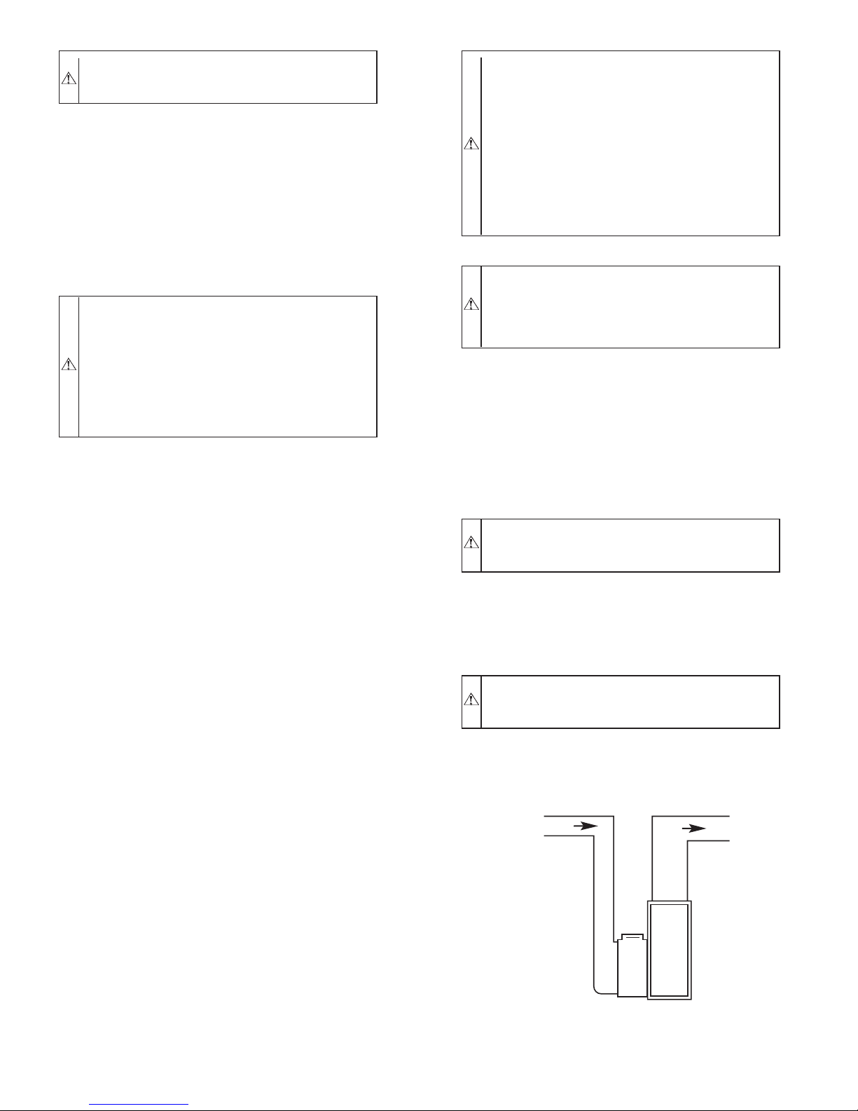
1. Filters installed in media cabinet adjacent to furnace (see
Fig. 2)
AIR FLOW
A99294
Fig. 2—Model 393AAV Upflow Furnace
a. Turn off electrical supply to furnace
—2—
b. Remove filter cabinet door.
c. Slide filter out of cabinet.
d. If equipped with permanent, washable filter, clean filter
by spraying cold tap water through filter in opposite
direction of airflow. Rinse filter and let dry. Oiling or
coating of the filter is not recommended.
e. If equipped with factory-specified disposable media
filter, replace only with media filter having the same part
number and size.
f. Slide filter into cabinet.
g. Replace filter cabinet door.
h. Turn on electrical supply to furnace.
2. Filters installed in side(s) and/or bottom of blower compartment (See Fig. 2)
a. Disconnect electrical power before removing access
doors.
b. Remove blower and control access doors.
c. Release filter retainer from clip at front of furnace
casing. (See Fig. 2.) For side return, clips may be used on
either or both sides of the furnace.
d. Slide filter(s) out.
e. Furnaces are equipped with permanent, washable filters.
Clean filters with tap water. Spray water through filter in
opposite direction of airflow.
f. Rinse and let dry. Oiling or coating of filter is NOT
recommended or required.
g. Reinstall filter(s)
h. Replace blower and control access doors
i. Restore electrical power to furnace.
II. BLOWER MOTOR AND WHEEL
The following items should be performed by a qualified service
technician:
To ensure long life, economy, and high efficiency, clean accumulated dirt and grease from blower wheel and motor annually.
The inducer and blower motors are pre-lubricated and require no
additional lubrication. These motors can be identified by the
absence of oil ports on each end of the motor.
Clean blower motor and wheel as follows:
1. Turn off electrical supply to furnace.
2. Remove control and blower access door.
3. Disconnect blower leads from furnace control. Notice wire
color and location for reassembly.
All other factory wires can be left connected, but field
thermostat connections may need to be disconnected depending on their length and routing.
4. Remove 2 screws securing control and transformer support
to furnace.
5. Hang control and transformer support to side of furnace
casing.
6. Remove screws holding blower assembly to blower deck
and slide blower assembly out of furnace.
7. Clean blower wheel and motor using a vacuum with soft
brush attachment. Do not remove or disturb balance weights
(clips) on blower wheel blades. The blower wheel should
not be dropped or bent as balance will be affected.
8. If a greasy residue is present on blower wheel, remove
wheel from the blower housing and wash it with an
appropriate degreaser. To remove wheel:
a. Mark blower wheel location on shaft before disassembly
to ensure proper reassembly.
b. Loosen setscrew holding blower wheel on motor shaft.
NOTE: Mark blower mounting arms, motor, and blower housing
so motor and each arm is positioned at the same location during
reassembly.
c. Mark blower wheel orientation and cutoff plate location
to ensure proper reassembly.
d. Remove screws securing cutoff plate and remove cutoff
plate from housing.
e. Remove bolts holding motor and motor mounts to
blower housing and slide motor and mounts out of
housing. Disconnect capacitor and ground wire attached
to blower housing before removing motor. Motor mount
belly band need not be removed unless motor is to be
replaced.
f. Remove blower wheel from housing.
CAUTION: The blower wheel should not be dropped or
bend as balance will be affected.
9. Reassemble motor and blower by reversing items 9a
through 9f. Be sure to reattach ground wire.
10. Reinstall blower assembly in furnace.
11. Reinstall control and transformer support assembly in
furnace.
12. Reconnect blower leads to furnace control.
Refer to furnace wiring diagram (See Fig. 7), and connect
thermostat leads if previously disconnected.
NOTE: Refer to Table 1 for motor speed lead relocation if leads
were not identified before disconnection
TABLE 1—SPEED SELECTOR
COLOR SPEED
Black High Cool
Yellow (When
Present)
Blue Medium Low Heat
Red Low Spare
White Common L2/COM
Medium High Spare
FACTORY-
ATTACHED
TO
CAUTION: Heating air speed selection MUST be ad-
justed to provide proper temperature rise as specified on
the rating plate. Failure to adjust the heating speed may
shorten heat exchanger life.
13. Turn on electrical supply. Manually close blower access
door switch. Use a piece of tape to hold switch closed.
Check for proper rotation and speed changes between
heating and cooling by jumpering R to W and then R to Y
on furnace control thermostat terminals.
—3—
WARNING: Blower access door switch opens 115-v
power to control center. No component operation can
occur. Caution must be taken when manually closing this
switch for service purposes. Failure to follow this warning could result in electrical shock, personal injury, or
death.
NOTE: If thermostat terminals are jumpered before blower access door switch is closed, blower will run for 90 sec before
beginning a heating or cooling cycle.
14. If furnace is operating properly, REMOVE TAPE TO
RELEASE BLOWER ACCESS DOOR SWITCH, replace
blower access door.
III. CLEANING HEAT EXCHANGER
The following steps should be performed by a qualified service
technician:
NOTE: If the heat exchangers get a heavy accumulation of soot
and carbon, they should be replaced rather than trying to clean
them thoroughly due to their intricate design. A build-up of soot
and carbon indicates that a problem exists which needs to be
corrected, such as improper adjustment of manifold pressure,
insufficient or poor quality combustion air, incorrect size, or
damaged manifold orifice(s), improper gas, or a restricted heat
exchanger. Action must be taken to correct the problem.
If it becomes necessary to clean the heat exchanger because of dust
or corrosion proceed as follows:
1. Turn gas and electrical power to furnace to OFF.
2. Remove control access door.
3. Disconnect vent connector from furnace flue collar.
4. Remove 2 screws that secure relief box. (See Fig. 2.)
5. Disconnect wires to the following components. Mark wires
to aid in reconnection of:
a. Blocked vent safeguard switch.
b. Inducer motor.
c. Pressure switch.
d. Limit overtemperature switch(es).
e. Gas valve.
f. Hot surface ignitor.
g. Flame-sensing electrode
h. Flame rollout switch(es), if applicable.
6. Remove complete inducer assembly and relief box from
furnace.
7. Remove 8 screws that secure flue collector box to center
panel. Be careful not to damage collector box.
8. Remove burner assembly and cell inlet plates.
IMPORTANT: Replace screws in center panel before cleaning.
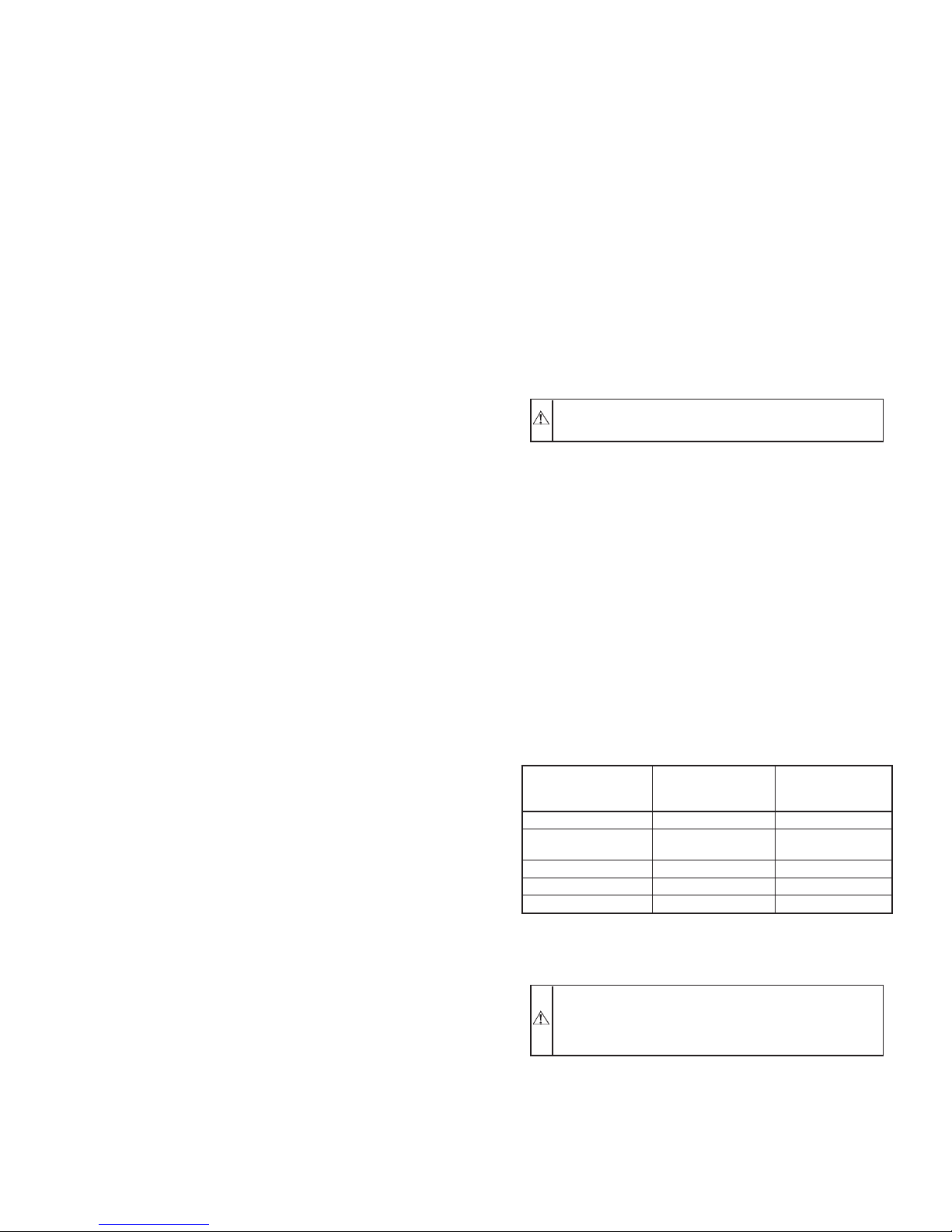
NOTE: Be very careful when removing burner assembly to avoid
breaking ignitor. See Fig. 3 for correct ignitor location.
9. Using field-provided small wire brush, steel spring cable,
reversible electric drill, and vacuum cleaner, clean cells as
follows:
a. Assemble wire brush and steel spring cable.
(1.) Use 48 in. of 1/4-in. diameter high-grade steel
spring cable (commonly known as drain clean-out
or Roto-Rootert cable).
(2.) Use 1/4-in. diameter wire brush (commonly known
as 25-caliber rifle cleaning brush).
NOTE: The materials needed in items (1.) and (2.) can usually be
purchased at local hardware stores.
11
CELL
PANEL
HOT
SURFACE
IGNITOR
ASSEMBLY
C
IGNITOR
L
7
8
"
C
BURNER
L
IGNITOR
ASSEMBLY
32
BURNER
13
32
"
Fig. 3—Position of Ignitor to Burner
(3.) Insert twisted wire end of brush into end of spring
cable, and crimp tight with crimping tool or strike
with ball-peen hammer. TIGHTNESS IS VERY
IMPORTANT.
(4.) Remove metal screw fitting from wire brush to
allow insertion into cable.
b. Clean each heat exchanger cell.
(1.) Attach variable-speed, reversible drill to end of
spring cable (end opposite brush).
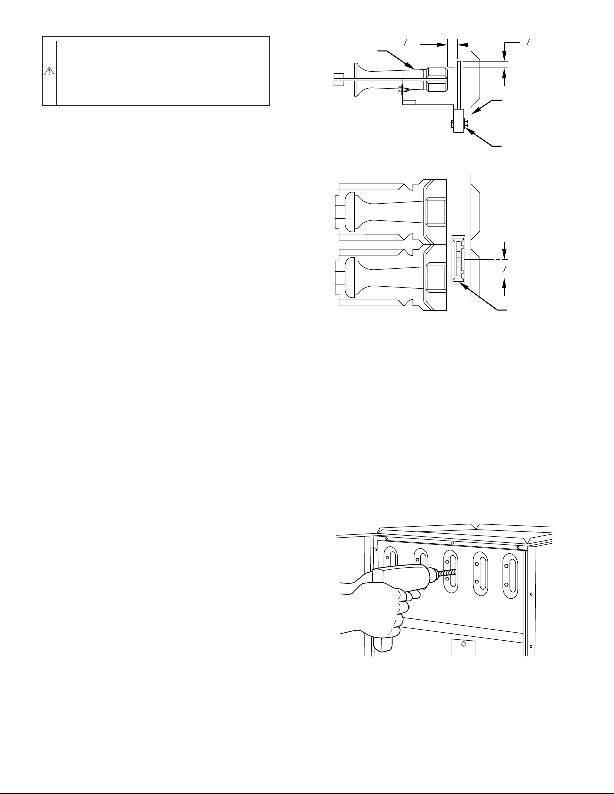
(2.) Insert brush end of cable into upper opening of cell
and slowly rotate with drill. DO NOT force cable.
Gradually insert at least 36 in. of cable into 2 upper
passes of cell. (See Fig. 4.)
Fig. 4–Cleaning Heat Exchanger Cell
(3.) Work cable in and out of cell 3 or 4 times to obtain
sufficient cleaning. DO NOT pull cable with great
force. Reverse drill and gradually work cable out.
(4.) Insert brush end of cable in lower opening of cell,
and proceed to clean 2 lower passes of cell in same
manner as 2 upper passes.
"
A93347
A91252
—4—
 Loading...