

Bryant FNCCAB series, FNCCAB-0014, FNCCAB-0017, FNCCAB-0021, FNCCAB-0024 Installation Instructions Manual
Page 1
Sizes:
014, 017, 021, 024
Installation Instructions
C04032
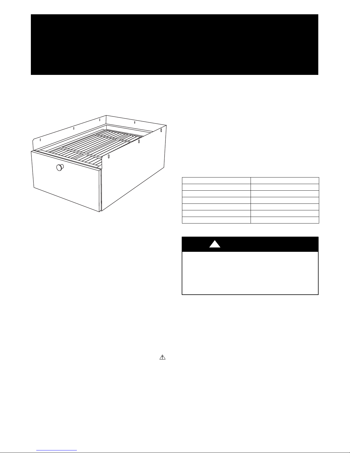
Fig. 1 -- FNCCAB High Efficiency Air Filtration System
NOTE: Read the entire instruction manual before starting the
installation.
SAFETY CONSIDERATIONS
Improper installation, adjustment, alteration, service, maintenance,
or use can cause explosion, fire, electrical shock, or other
conditions which may cause death, personal injury, or property
damage. Consult a qualified installer, service agency, or your
distributor or branch for information or assistance. The qualified
installer or agency must use factory--authorized kits or accessories
when modifying this product. Refer to the individual instructions
packaged with the kits or accessories when installing.
Follow all safety codes. Wear safety glasses, protective clothing,
and work gloves. Use quenching cloth for brazing operations.
Have fire extinguisher available. Read these instructions
thoroughly and follow all warnings or cautions included in
literature and attached to the unit.. Consult local building codes
and current editions of the National Electrical Code ( NEC ) NFPA
70. In Canada, refer to current editions of the Canadian electrical
code CSA 22.1.
Recognize safety information. This is the safety--alert symbol
When you see this symbol on the furnace and in instructions or
manuals, be alert to the potential for personal injury. Understand
the signal words DANGER, WARNING, CAUTION and NOTE.
The words DANGER, WARNING,andCAUTION are used with
the safety alert symbol. DANGER identifies the most serious
hazards which will result in severe personal injury or death.
WARNING signifies a hazard which could result in personal
injury or death. CAUTION is used to identify unsafe practices
FNCCAB
High Efficiency Filtration System
For Fan Coils
which may result in minor personal injury or product and property
damage. NOTE is used to highlight suggestions which will result
in enhanced installation, reliability, or operation.
INTRODUCTION
These instructions cover the installation, operation and
maintenance of FNCCAB High Efficiency Air Filtration System.
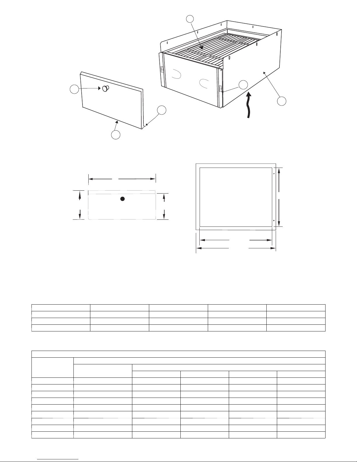
Become familiar with the components listed in Table 1. See Fig. 2.
Table 1 – FNCCAB Major Components
COMPONENT DESCRIPTION
1 Cabinet
2 Filter
3 Access Handle
4 Access Door
5 Door Latch Hardware
6 Door Alignment Table
DESCRIPTION AND USAGE
!
CAUTION
UNIT OPERATION AND SAFETY HAZARD
Failure to follow this caution may result in personal injury
and/or damage to the equipment.
Prior to installing this product, you should read these entire
instructions and follow all directions.
APPLICATION
This High Efficiency Air Filtration System must be used in a
forced air heating, cooling or ventilation system. This High
Efficiency Air Filtration System cleaner should be installed in the
system so that all the system air is circulated through this air
cleaner. The High Efficiency Air Filtration System will only
remove the airborne contaminants delivered to it. Maximum
performance is obtained when the system blower is set for
continuous operation.
.
INSTALLATION REQUIREMENTS
The location for the High Efficiency Air Filtration System is on the
return side of the fan coil next to the blower compartment. In this
location, both the blower motor and cooling coils will be kept
clean. Do not install the air cleaner in the discharge (supply) air
duct. The front of this unit must be readily accessible for periodic
inspection and replacement of filter to maintain maximum
efficiency and trouble--free operation.
Page 2
2
3
5
1
6
AIR FLOW
4
C04033
Fig. 2 -- FNCCAB Major Components
A
B
7 "8-7/8 "
19-1/2"
22-1/4"
Fig. 3 -- FNCCAB Dimensions
Table 2 – Dimensions and Airflow
MODELS FNCCAB---0014 FNCCAB---0017 FNCCAB---0021 FNCCAB---0024
Airflow (CFM) Range 600---900 600 --- 1350 600---2000 600--- 2200
A 14---5/16 --- in (36 cm) 1 7 --- 5 / 8 --- i n (4 5 cm ) 2 1 --- 1 / 8 --- i n (5 4 cm ) 2 4 --- 5 / 8 --- i n (6 3 cm )
B 1 1 --- i n ( 2 8 c m ) 14---11/32 --- in (36 cm) 1 7 --- 7 / 8 --- i n (4 5 cm ) 21--- 11/32- --in (54 cm)
Table 3 – Typical Pressure Drop
TYPICAL PRESSURE DROP
Airflow Range
(CFM)
600 .044 .125 .060 .040 .015
800 .075 .150 .090 .060 .030
1000 .072 .250 .125 .070 .040
1200 .100 --- .180 .090 .060
1400 .092 --- .250 .140 .090
1600 .120 --- --- .187 .125
1800 .152 --- --- .230 .150
2000 .187 --- --- .280 .190
2200 --- --- --- --- .250
Typical Factory--- supplied
Filter in Fan Coil Unit
FNCCAB --- 0014 FNCCAB --- 0017 FNCCAB --- 021 FNCCAB --- 0024
Resistance (in. w.c.)
Model Number
C04031
2
Page 3

FNCCAB Typical Horizontal Installation
Screws to be removed and reused when
Installing FNCCAB to Fan Coil (2-Left Side, 2-Right SIde)
FNCCAB Typical Vertical (Upflow or Downflow) Installation
Fig. 4 -- Typical Installation
C04029
CONNECTING FLANGE
MOUNTING HOLES
Fig. 5 -- Mounting Holes and Mounting Flange
SELECT LOCATION FOR THE AIR CLEANER
Select a location that is readily accessible for periodic inspection
and cleaning. Allow a minimum of 26--in. in front of the access
panel for filter removal and replacement. For complete unit
dimensions refer to Fig. 3.
IMPORTANT: Failure to replace filter can cause damage to the
system.
This High Efficiency Air cleaner can be mounted in several
positions. See Fig. 4 for proper air cleaner mounting with a variety
of installation styles.
!
CAUTION
MOUNTING HOLES
C04034
!
WARNING
ELECTRICAL SHOCK HAZARD
Failure to follow this warning could result in personal injury
or death.
Only a trained, experienced service person should install this
air cleaner. A thorough checkout of the unit installation should
be completed before unit operation. Before performing
installation, service or maintenance operations on unit, turn off
all power to unit. TAG DISCONNECT SWITCH WITH
LOCKOUT TAG.
CUT HAZARD
Failure to follow this caution may result in personal injury.
Sheet metal parts may have sharp edges or burrs. Use care and
wear appropriate protective clothing and gloves when
handling these parts.
3
Page 4

INSTALLATION
1. Turn off power disconnect and install lockout tag.
2. Check the airflow rating given on this product to make sure
it is suitable for your application.
3. Remove the fan coil filter door and the factory supplied
1--in air filter. Discard filter and reinstall filter door.
NOTE: The air cleaner cannot remove existing dirt from the
blower and ducts.
NOTE: The following is a typical installation of this air cleaner on
an upflow furnace. You may have to alter the installation to fit your
specific application.
4. Remove screws from the fan coil edge (return side) and retain for use once FNCCAB is in place.
5. Slide FNCCAB installation connecting flange over fan coil
cabinet (return side) edge.
6. Mounting holes are provided for simple connection to unit
cabinet. See Fig. 5. The clearance slots/holes are sized for
#10 sheet metal screws or pop rivets. Reinstall the four
screws removed in item 4 above, then shoot screws into remaining four clearance slots/holes of FNCCAB. If the adjoining duct work is flanged, install the screws so that the
screw heads are inside the cabinet. This will prevent damage
to the filter during removal and installation.
7. After the cabinet has been secured, use caulk or tape to seal
connecting seams airtight to the bottom opening as required.
8. If not already installed, slide filter into mounted FNCCAB.
9. Install access door and ensure a tight seal. See Fig. 6.
OWNERS MANUAL SECTION
FNCCAB and FILFNC Maintenance
How to Maintain your air cleaner
The filter media in your cabinet MUST be replaced periodically.
The frequency of filter replacement is best determined by visual
examination.
On average, filters of this type should be replaced before each
heating and each cooling season under normal usage (or at least
yearly under minimum usage).
Steps for Replacing Filter
1. Turn off power to blower.
2. Open access door by pulling the handle. Remove door completely.
3. Pull used filter straight out of cabinet and discard.
4. Remove new filter from packaging.
5. Slide new filter into cabinet with Air--Flow arrow pointing
in the direction of air flow (toward fan coil cabinet).
6. Replace access door. See Fig. 6.
7. Turn on power to blower.
REPLACEMENT FILTERS
REPLACEMENT FILTERS FOR YOUR HIGH
EFFICIENCY AIR FILTRATION SYSTEM
Remember, periodic inspection and replacement of your filter will
ensure high efficiency air cleaning. Contact your HVAC dealer for
replacement filters. See Table 4.
2a
1a
2b
1b
FNCCAB Door Latching Procedure
Step 1-Fully Insert Door Alignment Tabs (1a) into Cabinet Slots (1b)
Step 2-Firmly Pivot Door upward to Capture Door Tabs (2a)
into Cabinet Latching Mechanism (2b)
Fig. 6 -- Door Assembly Detail View
Table 4 – Replacement Filter Order Number
MERV 8 FILXXFNC0014 FILXXFNC0017 FILXXFNC0021 FILXXFNC0024
MERV 11 FILXXFNC0114 FILXXFNC0117 FILXXFNC0121 FILXXFNC0124
Quantity per carton 2 2 2 2
C04035
Copyright 2012 CAC / BDP D 7310 W. Morris St. D Indianapolis, IN 46231 Edition Date: 12/12
Manufacturer reserves the right to change, at any time, specifications and designs without notice and without obligations.
C a t a l o g N o : I M --- F N C B --- 0 2
R e p l a c e s : I M --- F N C B --- 0 1
4
 Loading...