

Page 1
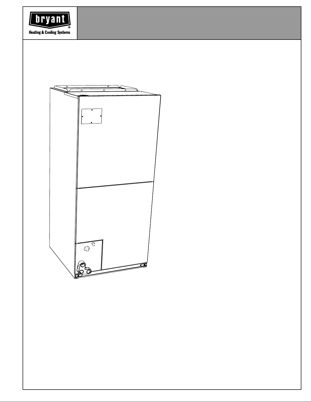
FAN UNIT
FH4B
Sizes 001 thru 004
PRACTICALITY & PERFORMANCE
Reliability, dependability, and great value are built into the FH4B
Fan Units. The unit is compact and easy to install, with capacities
ranging from 800 to 2000 CFM. The units are the right choice if
you need versatility and affordability in a fan unit.
These fan coil units offer an air handler for practical, no-nonsense application and outstanding performance. The multipoise
units allow greater flexibility to meet your upflow, downflow, or
horizontal installation requirements, and offer multiple electric
entry to permit quick, hassle-free hookup (003 and 004 when
coupled with coil are upflow/downflow only). All models come
fully equipped with solid-state cooling controls.
The FH4B, with its 3-speed motor and field-installed heater
package, provides the application versatility required for most
installations. Heater packages are available from 3- through 30kw, either fused or with a circuit breaker, or non-fused for 10-kw
and less.
Form No. PDS FH4B.01.3
Page 2
FEATURES
Prepainted galvanized sheet metal
•
•
Cooling controls with every unit
3-speed motor
•
•
Unique cabinet design to meet air leakages regulations
•
Factory-supplied cleanable filter
Easy access filter for cleaning—no tools required
•
•
Air sealed filter door
Field-installed heater packages 3- through 30-kw, fused, circuit breaker, non-fused (10-kw and down)
•
•
Factory-supplied power plug
Control board with replaceable 5-amp blade type auto fuse
•
•
Foil-faced high-density super thick R-4.2 insulation
Multiple electric entry
•
•
HUD approved for manufactured housing
•
40-va, 208/230-v transformer
All models listed with UL (U.S. and Canada) and ARI
•
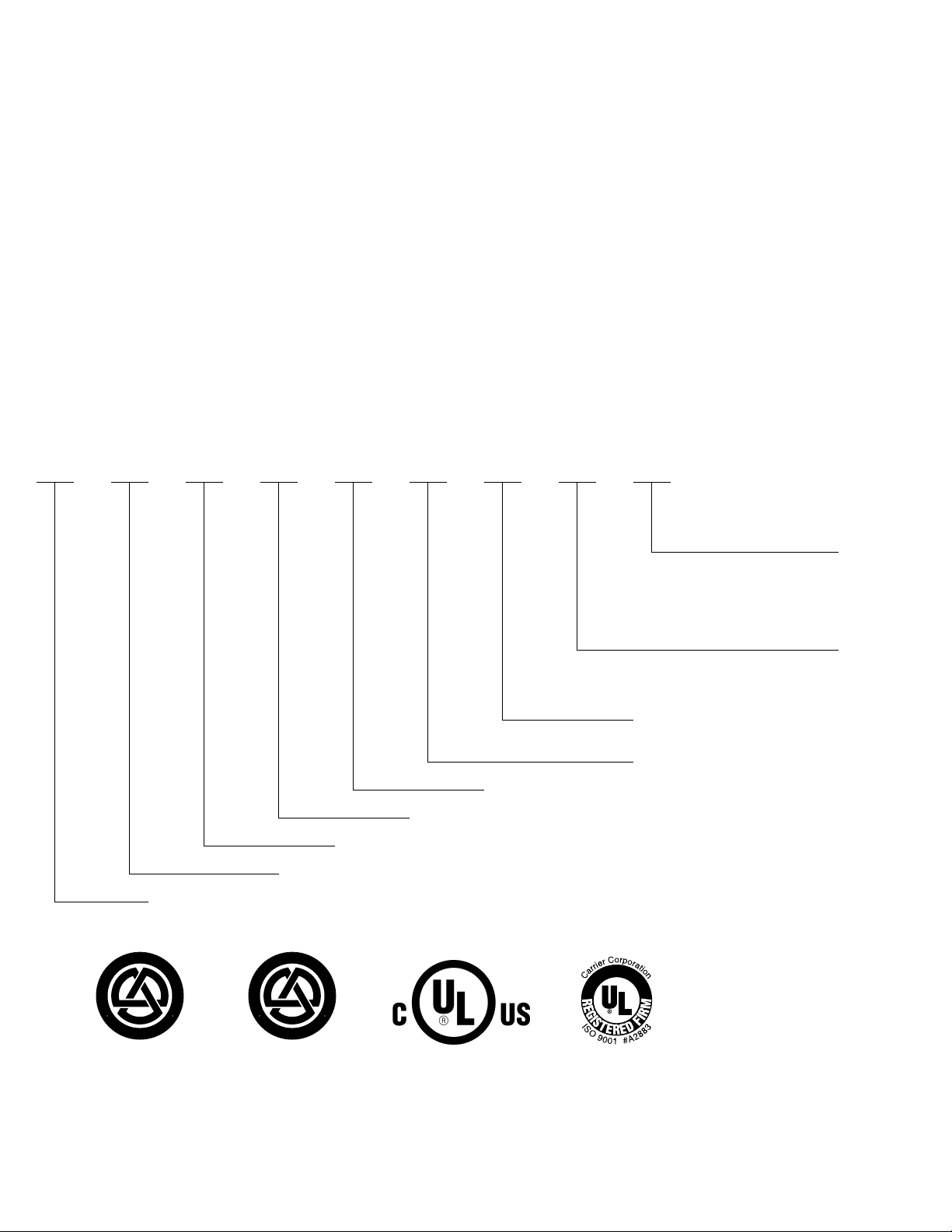
MODEL NUMBER NOMENCLATURE
F H 4 B N F 001 015 AEAA
Electric Heater (kw)
003 015
005 020
008 024
009 030
010
001—1800 CFM
002—1200 CFM
003—1600 CFM
004—2000 CFM
F— Single Piece Cabinet with 1 in.
Super Thick Insulation
N—208/230-1-60
B—Series
4—Multipoise
H—Fan Unit
F—Fan Coil
A—Common Unit
E—Minor Engineering Change
A—Standard Unit
A—Standard Unit
T
O
D
E
A
I
R
F
I
I
T
A
R
S
E
C
R
E
R
U
T
C
A
F
U
N
A
M
A
R
C
O
M
H
P
E
A
Y
R
A
T
I
N
U
I
S
L
T
Y
P
I
U
N
M
G
P
W
I
T
H
®
E
T
Q
N
U
E
I
P
M
0
4
2
D
T
A
R
N
A
D
T
O
D
E
A
I
R
F
I
I
T
A
R
S
E
C
R
A
I
R
E
C
R
U
T
C
A
F
U
N
A
M
O
Y
N
R
D
A
I
T
T
I
N
U
E
T
Q
N
U
E
I
P
M
A
R
I
2
S
D
T
A
R
N
A
D
CERTIFICATION APPLIES ONLY WHEN THE
COMPLETE SYSTEM IS LISTED WITH ARI.
C
O
M
P
L
Y
I
N
I
O
G
N
I
N
W
G
I
T
H
0
1
REGISTERED
QUALITY
SYSTEM
—2—
Page 3
✓
✓
✓
✓
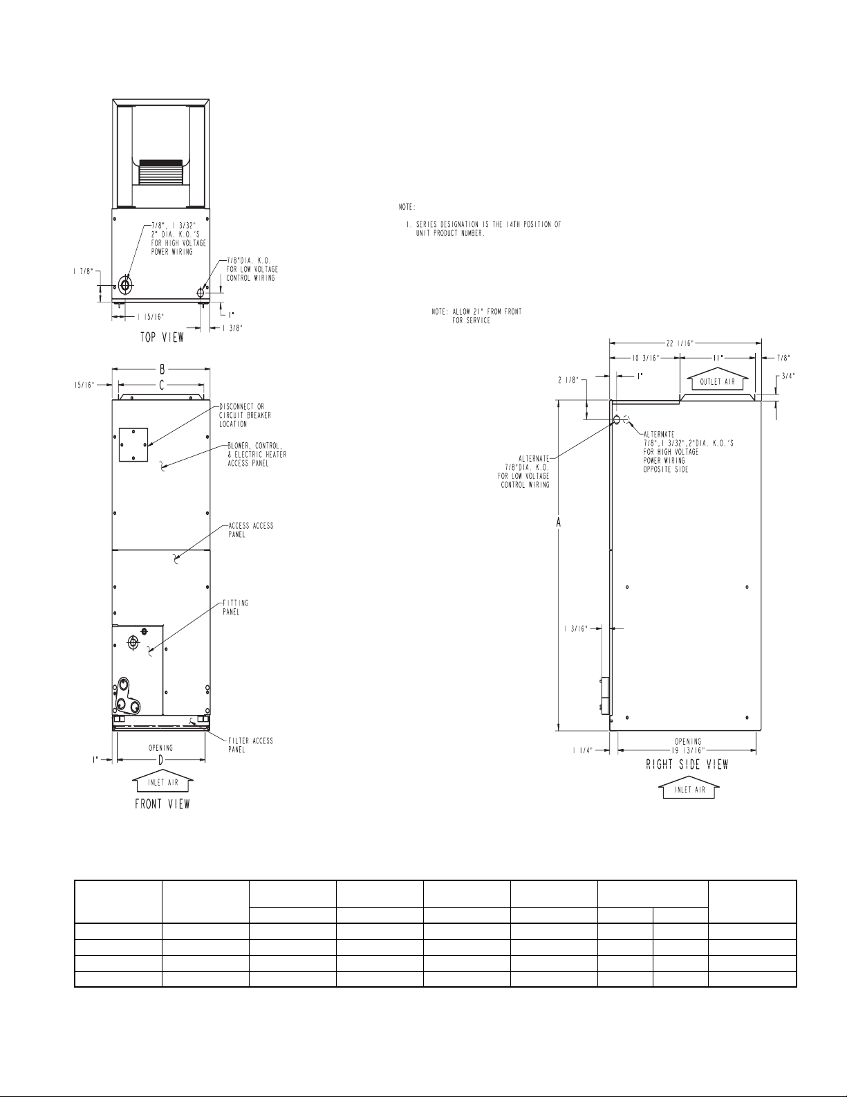
DIMENSIONS
ABCF
UNIT SERIES
FH4BNF001 E 42-11/16 14-5/16 12-7/16 12-5/16
FH4BNF002 E 49-5/8 17-5/8 15-3/4 15-5/8
FH4BNF003 E 49-5/8 21-1/8 19-1/4 19-1/8
FH4BNF004 E 53-7/16 21-1/8 19-1/4 19-1/8
—3—
ACCY. COIL
CONFIGURATION
A02300
OPERATING
WEIGHT (Lb)In. In. In. In. SLOPE “A”
175
192
106
114.5
Page 4
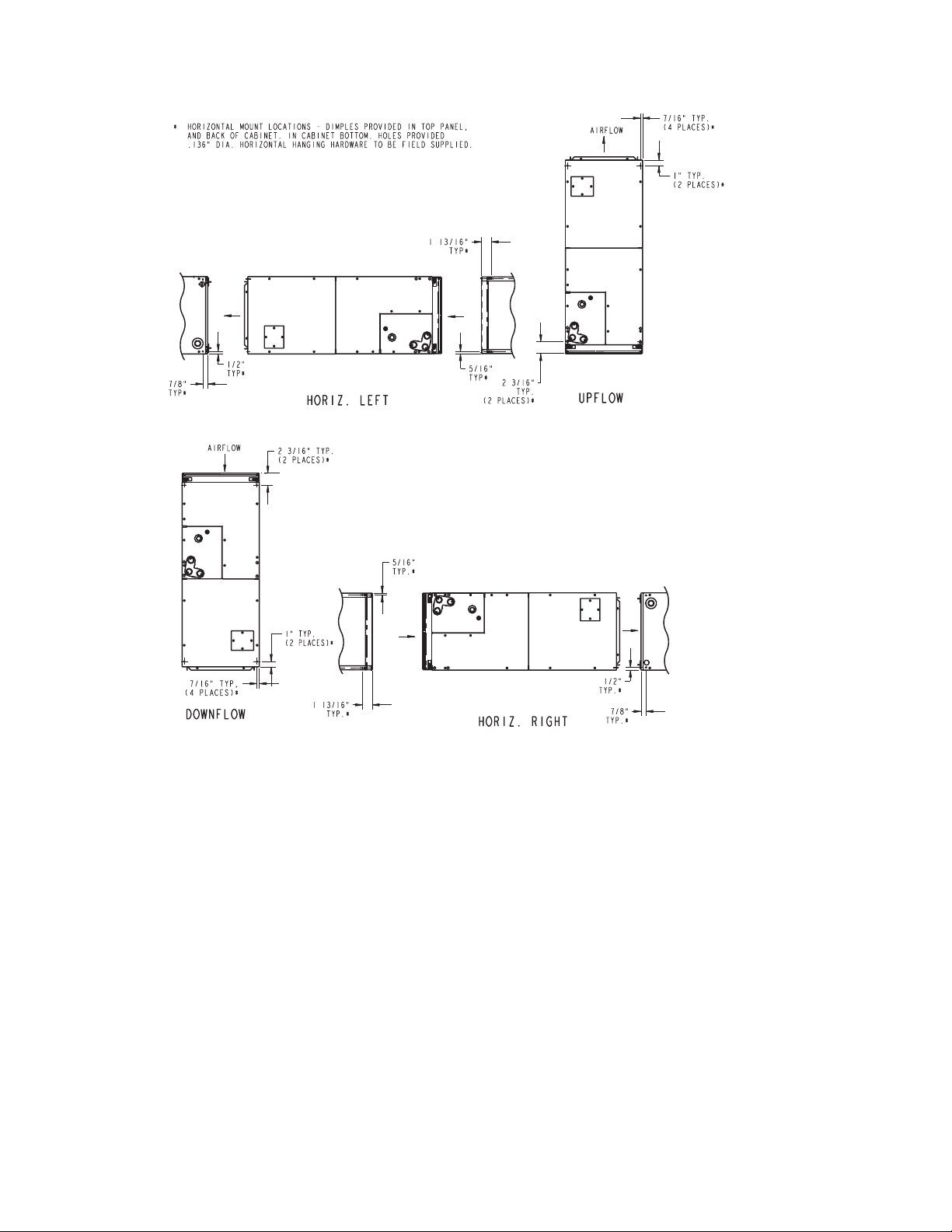
DIMENSIONS Continued
—4—
A02301
Page 5

DIMENSIONS Continued
POWER ENTRY
OPTIONS
24-IN. FRONT SERVICE
CLEARANCE
2 Ω
FIELD SUPPLIED
SUPPLY DUCT
LOW VOLT
ENTRY
OPTIONS
UNIT
FH4B001
FH4B002
1 Ω
″
19″
A
″
A
12 In.
17 In.
FIELD MODIFIED
SIDE RETURN
LOCATION FOR
SLOPE COIL
UNITS ONLY
FIELD SUPPLIED
RETURN PLENUM
*Side Return not compatible when used in conjunction with accessory cooling coil
Field-modified Side Return Location
For Slope Coils Only
A02294
—5—
Page 6

SPECIFICATIONS
UNIT SIZE 001 002 003 004
FAN
Air Discharge
CFM (Nominal)
Motor Hp (PSC)
FILTER 21-1/2 x 13 21-1/2 x 16-3/8 21-1/2 x 19-7/8
850
1/4
1300
1/3
1700
3/4
AIRFLOW PERFORMANCE* (CFM)
EXTERNAL STATIC PRESSURE (IN. WC)
SIZE
FH4B001
FH4B002
FH4B003
FH4B004
BLOWER
SPEED
HIGH 1173 1270 1135 1225 1090 1170 1045 1126 993 1058 925 981
MED 900 1025 875 991 847 963 810 922 768 869 695 802
LOW 579 687 560 663 537 639 505 610 451 554 384 467
HIGH 1630 1841 1605 1798 1567 1748 1525 1696 1480 1629 1415 1560
MED 1244 1438 1225 1407 1190 1383 1170 1342 1141 1308 1100 1265
LOW 1001 1172 985 1147 955 1116 930 1094 908 1062 850 1024
HIGH ————2118 — 2060 2202 1949 2106 1853 1989
MED 1757 2061 1745 2016 1734 1985 1716 1943 1686 1890 1624 1802
LOW 1290 1535 1286 1535 1281 1528 1277 1515 1263 1467 1245 1431
HIGH ————2257 — 2235 — 2188 — 2113 2336
MED ——1930 2215 1914 2196 1887 2163 1838 2106 1787 2047
LOW 1620 1881 1620 1870 1613 1864 1607 1853 1594 1836 1562 1802
* With factory approved filter, 10-kw elec heat 001 and 002 sizes, 15-kw elec heat 003 and 004 sizes 230-volt.
0.10 0.20 0.30 0.40 0.50 0.60
208 230 208 230 208 230 208 230 208 230 208 230
2000
3/4
AIRFLOW PERFORMANCE WITH ACCESSORY COIL (CFM)
MODEL
AND
SIZE
FH4B001 WITH
KFAEC0501024
FH4B002 WITH
KFAEC0601036
FH4B003 WITH
KFAEC0301048
FH4B004 WITH
KFAEC0401060
BLOWER
MOTOR
SPEED
HIGH
MED 835 900 795 855 745 800 690 740
LOW 605 695 575 665 530 625 485 580
HIGH
MED 1235
LOW 1035 1185 1010 1150 980 1115 940 1070
HIGH
MED 1740
LOW 1425 1605 1395 1555 1360 1495 1315 1430
HIGH
MED
LOW 1680 1895 1655 1855 1625 1810 1595 1765
0.10 0.20 0.30 0.40 0.50 0.60
208 230 208 230 208 230 208 230 208 230 208 230
945 975 900 930 840 870 780 805 695 725 560 595
1485 1550 1425 1490 1365 1420 1300 1350 1230 1275 1150 1190
1380 1200 1325 1160 1265 1110 1210 1055 1140 985 1070
1880 1935 1785 1830 1700 1735 1615 1645 1520 1555 1430 1460
1840 1660 1750 1585 1660 1510 1575 1435 1485 1350 1390
2145 2245 2085 2185 2030 2115 1965 2045 1905 1975 1830 1895
2025 2175 1970 2110 1915 2050 1860 1990 1805 1905 1740 1830
NOTES: 1. Airflow based upon dry coil at 230v with factory approved accessory filter and electric heater (10-kw electric heat, sizes 001 and 002;
15-kw electric heat, sizes 003 and 004).
2. To avoid potential for condensate blowing out of drain pan prior to making drain trap:
—Return static pressure must be less than 0.4 in. wc
—Horizontal applications of 048-070 sizes must have supply static greater than 0.20 in. wc
Airflow outside max ARI airflow of 450 cfm/ton on 018-154 sizes
Airflow above 400 cfm/ton on 060-070 sizes. Airflows in this region could result in condensate blowing off coil or splashing out of drain pan.
TOTAL EXTERNAL STATIC PRESSURE (IN. WC)
610 650 470 510
425 510 340 395
890 1010 825 935
1255 1360 1170 1270
1555 1705 1500 1645
FILTER STATIC PRESSURE DROP (IN. WC)
CFM
UNIT SIZE
001 — 0.044 0.075 0.110 —————
002 ———0.072 0.100 0.130 ———
003 —————0.092 0.120 0.152 —
004 ——————0.120 0.152 0.187
400 600 800 1000 1200 1400 1600 1800 2000
—6—
Page 7

FAN COIL ELECTRICAL DATA
(UNITS WITHOUT ELECTRICAL HEAT)
UNIT
SIZE
001 208/230 1.8 2.3 14 15
002 208/230 2.7 3.4 14 15
003 208/230 4.3 5.4 14 15
004 208/230 5.4 6.8 14 15
* Use copper wire only. 75°C must be used in this application. When using non-metallic (NM) sheathed cable, wire size required should be based on
that of 60°C conductors, instead of wire sizes shown in table above per NEC 1999 Article 336-26.
FLA — Full Load Amps
NOTE: If branch circuit wire length exceeds 100 ft., consult NEC 215-2 to determine maximum wire length. Use 2% voltage drop.
VOLTS
(1 PHASE) FLA
MIN
CKT
AMPS
BRANCH CIRCUIT
Min Wire
Size AWG* Fuse Amps
ELECTRIC HEATER INTERNAL PROTECTION*
HEATER KW PHASE
31 ——
51 — 1/60
81 — 1/60
10 1 — 1/60
15 1 2/30 – 2/60 2/60
20 1 4/60 2/60
24 3/1 6/60 —
30 3/1 6/60 —
9 1/3** ——
15 3 ——
18 3 ——
* 5-, 8-, 10-kw factory-installed heat has no internal protection. 15-kw factory-installed heat is internally protected with fuses.
** KFCEH1401N09 is single phase only.
† Circuit breakers are 2 pole.
FUSES
QTY/SIZE
CKT BKR
QTY/SIZE†
ELECTRIC HEATERS
HEATER
PART NO.
KFCEH0401N03 3 230/1 3 None 001 9,400
KFCEH0501N05 5 230/1 5 None 001, 002 15,700
KFCEH0801N08 8 230/1 8 None 001–004 25,100
KFCEH0901N10 10 230/1 10 None 001–004 31,400
KFCEH3201F20 20 230/1 5, 20 Fuse‡ 002–004 62,800
KFCEH1601315 15 230/3 5, 15 None 002–004 47,100
KFCEH2001318 18 230/3 6, 12, 18 None 003, 004 56,500
KFCEH3401F24 24 230/3* 8, 16, 24 Fuse 003, 004 75,300
KFCEH3501F30 30 230/3* 10, 20, 30 Fuse 003, 004 94,100
KFCEH2401C05 5 230/1 5 Circuit Breaker 001, 002 15,700
KFCEH2501C08 8 230/1 8 Circuit Breaker 001, 002 25,100
KFCEH2601C10 10 230/1 10 Circuit Breaker 001–004 31,400
KFCEH3301C20 20 230/1 5, 20 Circuit Breaker 002–004 62,800
KFCEH2901N09 9 230/1† 3, 9 None 002–004 28,200
KFCEH3001F15 15 230/1 5, 15 Fuse‡ 001–004 47,100
KFCEH3101C15 15 230/1 5, 15 Circuit Breaker 001–004 47,100
KW
@ 240V VOLTS/PHASE
STAGES (KW
OPERATING)
INTERNAL
CIRCUIT
PROTECTION
FAN COIL SIZE
USED WITH
HEATING CAP. **
@ 230V
—7—
Page 8

SMART HEAT
HEATER
PART NO.
KFCEH0101H10 10 230/1 3, 6, 9 None‡ 001, 002 31,400
KFCEH0201H15 15 230/1 3, 8, 11, 15 Fuse 001–003 47,100
KFCEH0301H20 20 230/1 5, 10, 15, 20 Fuse 002–004 62,800
* Field convertible to 1 phase.
† KFAEH2501N09 is field convertible to 3 phase.
‡ Single point wiring kit required for these heaters in Canada.
** Blower motor heat not included.
When using units with 20-, 24-, and 30-kw electric heaters, maintain a 1-in. clearance from combustible materials to discharge plenum and ductwork,
and maintain a distance of 36 in. from the unit. Use an accessory downflow base to maintain proper clearance on downflow installations.
Use flexible connectors between ductwork and unit to prevent transmission of vibration. When electric heater is installed, use heat resistant material
for flexible connector between ductwork and unit at discharge connection. Ductwork passing through unconditioned space must be insulated and
covered with vapor barrier.
KW
@ 240V VOLTS/PHASE
STAGES
(KW OPERATING)
INTERNAL
CIRCUIT
PROTECTION
FAN COIL SIZE
USED WITH
HEATING CAP. **
@ 230V
ESTIMATED SOUND POWER LEVEL (dBA)
CONDITIONS OCTAVE BAND CENTER FREQUENCY*
UNIT
SIZE
FH4-001 800 0.25 66.0 62.0 58.0 55.0 53.0 51.0 47.0
FH4-002 1200 0.25 67.8 63.8 59.8 56.8 54.8 52.8 48.8
FH4-003 1600 0.25 69.0 65.0 61.0 58.0 56.0 54.0 50.0
FH4-004 2000 0.25 70.0 66.0 62.0 59.0 57.0 55.0 51.0
* Estimated sound power levels have been derived using the method described in the 1987 ASHRAE HVAC Systems & Applications Handbook,
Chapter 52, p. 52.7
CFM
Ext Static
Pressure 63 125 250 500 1000 2000 4000
—8—
Page 9

Dual Circuit
208/230V (Ft)‡‡
Max Wire Length
Single
Circuit
Dual Circuit
208/230V
Max Fuse/Ckt Bkr Amps
Single
Circuit
Dual Circuit
208/230V
Min Gnd Wire Size
BRANCH CIRCUIT
Single
Circuit
Dual Circuit
208/230V††
Min Wire Size (AWG)
Single
Circuit
Dual Circuit
208/230V (Ft)‡‡
Max Wire Length
Single
Circuit
Dual Circuit
208/230V
Max Fuse/Ckt Brk Amps
Single
Circuit
Dual Circuit
208/230V
Min Gnd Wire Size
BRANCH CIRCUIT
Single
Circuit
Dual Circuit
208/230V††
Min Wire Size (AWG)
Single
Circuit
208/230V (FT)‡‡
MAX WIRE LENGTH
208/230V
MAX FUSE/CKT BKR AMPS
208/230V
MIN GND
WIRE SIZE
208/230V††
MIN WIRE SIZE (AWG)
Dual Circuit
208/230V**
Min Ampacity
Single
Circuit
ELECTRIC HEATER ELECTRICAL DATA
Dual Circuit
208/230V
HEATER AMPS
Single
Circuit
CIRCUIT
INTERNAL
PROTECTION
PHASE
KW
HEATER
PART NO.
5 3.8 1 None 18.1/20.0 ——26.0/28.4 ——10/10 ——10/10 ——30/30 ——66/66 ——
5 3.8 1 None 18.1/20.0 ——31.2/33.5 ——8/8 ——10/10 ——35/35 ——85/88 ——
240v 208v L1,L2 L3,L4 L1,L2 L3,L4 L1,L2 L3,L4 L1,L2 L3,L4 L1,L2 L3,L4 L1,L2 L3,L4
5 3.8 1 Ckt Bkr 18.1/20.0 ——26.0/28.4 ——10/10 ——10/10 ——30/30 ——66/66 ——
1
2
1
KFCEH0401N03 3 2.3 1 None 10.9/12.0 ——15.9/17.3 ——12/12 ——12/12 ——20/20 ——67/68 ——
KFCEH2401C05
KFCEH0501N05
KFCEH0501N05
5 3.8 1 Ckt Bkr 18.1/20.0 ——31.2/33.5 ——8/8 ——10/10 ——35/35 ——85/88 ——
2
— 9 6.8 3 None 18.8/20.8 ——32.0/34.5 ——8/8 ——10/10 ——35/35 ——83/85 ——
KFCEH0801N08 8 6.0 1 None 28.9/32.0 ——44.7/48.5 ——8/8 ——10/10 ——45/50 ——59/60 ——
KFCEH2501C08 8 6.0 1 Ckt Bkr 28.9/32.0 ——44.7/48.5 ——8/8 ——10/10 ——45/50 ——59/60 ——
KFCEH2401C05
KFCEH0901N10 10 7.5 1 None 36.2/40.0 ——53.8/58.5 ——6/6 ——10/10 ——60/60 ——78/80 ——
KFCEH2901N09*** 9 6.8 1 None 32.8/36.0 ——49.5/53.5 ——8/6 ——10/10 ——50/60 ——54/87 ——
KFCEH1601315 15 11.3 3 None 31.3/34.6 ——47.7/51.8 ——8/6 ——10/10 ——50/60 ——56/90 ——
KFCEH3001F15*** 15 11.3 1 Fuse 54.2/59.9 36.2/40.0 18.1/20.0 76.3/83.4 53.8/58.5 22.7/25.0 4/4 6/6 10/10 8/8 10/10 10/10 80/90 60/60 25/25 88/89 78/80 75/76
KFCEH3101C15*** 15 11.3 1 Ckt Bkr — 36.2/40.0 18.1/20.0 — 53.8/58.5 22.7/25.0 — 6/6 10/10 — 10/10 10/10 — 60/60 25/25 — 78/80 75/76
KFCEH2001318 18 13.5 3 None 37.6/41.5 ——55.5/60.4 ——6/6 ——10/8 ——60/70 ——76/77 ——
KFCEH3201F20*** 20 15.0 1 Fuse 72.3/79.9 36.2/40.0 36.2/40.0 98.9/108.4 53.8/58.5 45.3/50.0 3/2 6/6 8/8 8/6 10/10 10/10 100/110 60/60 50/50 85/109 78/80 59/59
KFCEH2601C10 10 7.5 1 Ckt Bkr 36.2/40.0 ——53.8/58.5 ——6/6 ——10/10 ——60/60 ——78/80 ——
KFCEH3301C20*** 20 15.0 1 Ckt Bkr — 36.2/40.0 36.2/40.0 — 53.8/58.5 45.3/50.0 — 6/6 8/8 — 10/10 10/10 — 60/60 50/50 — 78/80 59/59
SMART HEAT ELECTRICAL DATA
30 22.5 1 Fuse 109.0/120.0 ——144.8/158.5 ——0/00 ——6/6 ——150/175 ——117/150 ——
24 18.0 3 Fuse 50.1/55.4 ——71.2/77.8 ——4/4 ——8/8 ——80/80 ——94/95 ——
24 18.0 1 Fuse 86.7/95.5 ——116.9/127.9 ——1/1 ——6/6 ——125/150 ——115/116 ——
30 22.5 3 Fuse 62.6/69.2 ——86.8/95.0 ——3/3 ——8/8 ——90/100 ——97/98 ——
KFCEH3401F24†***
KFCEH3501F30†***
—9—
Dual Circuit
208/230V**
Min Ampacity
Single
Circuit
Dual Circuit
208/230V
HEATER AMPS
Single
Circuit
CIRCUIT
INTERNAL
PROTECTION
PHASE
KW
240v 208v L1,L2 L3,L4 L1,L2 L3,L4 L1,L2 L3,L4 L1,L2 L3,L4 L1,L2 L3,L4 L1,L2 L3,L4
HEATER
PART NO.
FIELD MULTIPOINT WIRING OF 24-AND 30-KW SINGLE PHASE
KFCEH0101H10 10 7.5 1 None 32.5/35.9 ——44.0/48.3 ——8/8 ——10/10 ——45/50 ——60/61 ——
KFCEH0201H15 15 11.3 1 Fuse 54.2/59.9 39.7/43.9 14.4/16.0 73.2/80.3 49.7/54.9 23.4/25.4 4/4 8/6 10/10 8/8 10/10 10/10 80/90 50/60 25/30 92/92 53/85 73/74
KFCEH0301H20 20 15.0 1 Fuse 72.3/79.9 36.2/40.0 36.2/40.0 97.2/106.7 52.0/56.8 45.3/50.0 3/2 6/6 8/8 8/6 10/10 10/10 100/110 60/60 50/50 87/111 81/82 93/93
208/230V**
MIN AMPACITY
208/230V
HEATER AMPS
PHASE
KW
240V 208V L1,L2 L3,L4 L5,L6 L1,L2 L3,L4 L5,L6 L1,L2 L3,L4 L5,L6 L1,L2 L3,L4 L5,L6 L1,L2 L3,L4 L5,L6
KFCEH3401F24† 24 18.0 1 28.9/32.0 28.9/32.0 28.9/32.0 44.7/48.5 36.2/40.0 36.2/40.0 8/8 8/8 8/8 10/10 45/50 40/40 40/40 59/60 73/73 73/73
KFCEH3501F30† 30 22.5 1 36.2/40.0 36.2/40.0 36.2/40.0 53.8/58.5 45.3/50.0 45.3/50.0 6/6 8/8 8/8 10/10 60/60 50/50 50/50 78/80 59/59 59/59
HEATER PART NO.
1. For fan coil sizes 018-036.
2. For fan coil sizes 042-060 and all FK4D, FV4B sizes.
3. Single circuit application of F15 and F20 heaters requires single-point wiring kit accessory
† Field convertible to 1 phase, single or multiple supply circuit.
(ANSI/NFPA 70).
‡ Field convertible to 3 phase.
** Includes blower motor amps of largest fan coil used with heater.
†† Copper wire must be used. If other than uncoated (non-plated), 75°C ambient, copper wire (solid wire for 10 AWG and smaller, stranded wire for larger than 10 AWG) is used, consult applicable tables of the National Electric Code
‡‡ Length shown is as measured 1 way along wire path between unit and service panel for a voltage drop not to exceed 2%.
NOTES:
*** Heaters are Intelligent Heat capable when used with the FK, FV fan coils and corporate 2-speed programmable thermostat (TSTATBBP2S01-A), or Thermidistat™ Control (TSTATBBPRH01-B).
Page 10

ELECTRIC HEATER STATIC PRESSURE DROP
The airflow performance data was developed using fan coils with 10-kw electric heaters (2 elements) in the 001 and 002 size units and
15-kw heaters (3 elements) in the 003 and 004 size units.
001, 002 003, 004
HEATER
ELEMENTS KW
0 0 +0.02 0 0 +0.04
1 3, 5 +0.01 2 8, 10 +0.02
2 8, 10 0 3 9, 15 0
3 9, 15 –0.02 4 20 –0.02
420–0.04 6 18, 24, 30 –0.10
The airflow performance data was developed using fan coils with 10-kw electric heaters (2 elements) in the 001 and 002 units and 15-kw heaters
(3 elements) in the 003 and 004 units. For fan coils with heaters of a different number of elements, the available external static at a given CFM from the
curve may be corrected by adding or subtracting available external static pressure as indicated above.
EXTERNAL STATIC
PRESSURE
CORRECTION
HEATER
ELEMENTS KW
EXTERNAL STATIC
PRESSURE
CORRECTION
ACCESSORIES
ITEM ACCESSORY PART NO.* FAN COIL SIZE USED WITH
Disconnect Kit KFADK0101DSC Cooling Controls and Heaters 3-kw through 10-kw
Downflow Base Kit KFACB0101CFB 001
KFACB0201CFB 002
KFACB0301CFB 003, 004
Downflow Conversion Kit KFADC0201SLP Slope Coil Units — 001, 002
KFADC0401ACL A-Coil Units — 003, 004
Single-Point Wiring Kit KFASP0101SPK Only with 15- and 20-kw Fused Heaters
Filter Kit (12 pack) KFAFK0112SML 001
KFAFK0212MED 002
KFAFK0312LRG 003, 004
Evaporator Coil KFAEC0501024 001
KFAEC0601036 002
KFAEC0301048 003
KFAEC0401060 004
Downflow/Horizontal Conversion Gasket Kit KFAHD0101SLP All
* Factory authorized and listed, field-installed.
Accessory Kits Description
Suggested and Required Use
1. Disconnect Kit
The kit is used to disconnect electrical power to the fan coil so service or maintenance may be performed safely.
SUGGESTED USE: FH4 units for 3-kw through 10-kw electric resistance heaters and cooling controls.
2. Downflow Base Kit
This kit is designed to provide a 1-in. minimum clearance between unit discharge plenum, ductwork, and combustible materials. It also provides a gap
free seal with the floor.
REQUIRED USE: This kit must be used whenever FH4 fan coils are used in downflow applications.
3. Downflow Conversion Kit
Fan coils are shipped from the factory for upflow or horizontal-left applications. Downflow conversion kits provide proper condensate water drainage
and support for the coil when used in downflow applications. Separate kits are available for slope coils and A-coils.
REQUIRED USE: This kit must be used whenever FH4A fan coils are used in downflow applications.
4. Single Point Wiring Kit
The single point wiring kit acts as a jumper between L1 and L3 lugs, and between the L2 and L4 lugs. This allows the installer to run 2 heavy-gage,
high-voltage wires into the fan coil rather than 4 light-gage, high-voltage wires.
SUGGESTED USE: FH4 fan coils with 15-kw and 20-kw fused heaters only.
5. Fan Coil Filter
The kit consists of 12 fan coil framed filters. These filters collect large dust particles from the return air entering the fan coil and prevent them from
collecting on the coil. This process helps to keep the coil clean, which increases heat transfer and in turn the efficiency of the system.
SUGGESTED USE: To replace filters in FH4 fan coils.
6. Evaporator Coil Kit
The kit contains a heating/cooling coil and drain pan.
SUGGESTED USE: Accessory coil used with FH4 fan unit.
7. Downflow/Horizontal Conversion Gasket Kit
This kit provides the proper gasketing of units when applied in either a Downflow or Horizontal application.
REQUIRED USE: FH4 fan coils.
—10—
Page 11

HEAT PUMP
MATCHED SYSTEM
VENTILATOR PLUS
ZONE PERFECT
EQUIPMENT CONTROLLER
PLUS
™
HUMIDIFIER
FAN COIL
ELECTRONIC
AIR CLEANER
A02295
—11—
Page 12

SERVICE TRAINING
Packaged Service Training programs are an excellent way to increase your
knowledge of the equipment discussed in this manual, including:
• Unit Familiarization • Maintenance
• Installation Overview • Operating Sequence
A large selection of product, theory, and skills programs is available, using popular
video-based formats and materials. All include video and/or slides, plus companion
book.
Classroom Service Training plus "hands-on" the products in our labs can mean
increased confidence that really pays dividends in faster troubleshooting, fewer
callbacks. Course descriptions and schedules are in our catalog.
CALL FOR FREE CATALOG 1-800-644-5544
[ ] Packaged Service Training [ ] Classroom Service Training
A94328
SPECIFICATIONS SUBJECT TO CHANGE WITHOUT NOTICE
UNIT MUST BE INSTALLED IN ACCORDANCE
WITH INSTALLATION INSTRUCTIONS
Cancels: PDS FH4B.01.2
Form PDS FH4B.01.3
© 2003 Bryant Heating & Cooling Systems, 7310 W. Morris St. Indpls, IN 46231 PRINTED IN U.S.A. Catalog No. 12FH-4B2 9-03
—12—
 Loading...