

Page 1
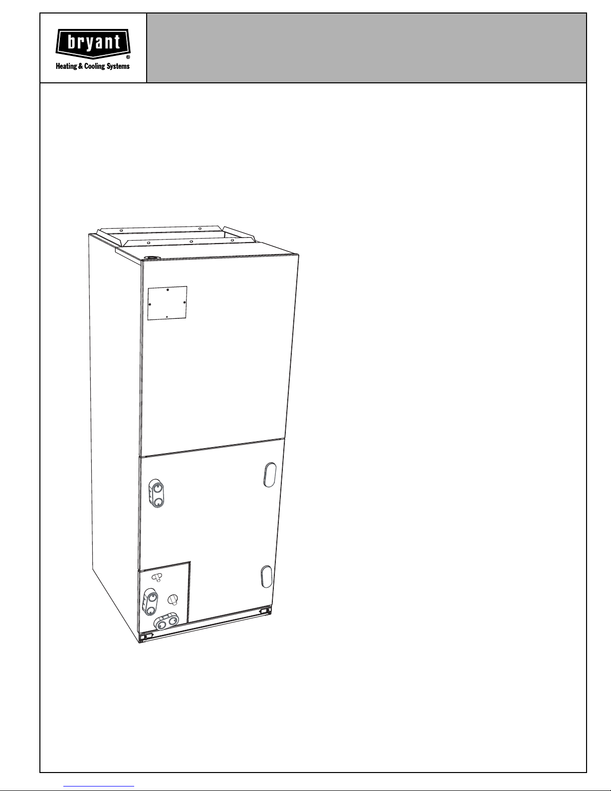
COMMUNICATING VARIABLE
SPEED FAN COIL PURON®
REFRIGERANT
PREMIUM ENVIRONMENTALLY SOUND
The FE4A is the premium air handler combining the proven
technology of Bryant fan coils with the environmentally sound
refrigerant, Puron®. The FE4A achieves an operation
advantage because the ECM (Electronically Commutated
Motor) combined with a Quantum Plus heat pump with Puron is
highly efficient at all possible operating speeds, and delivers the
precise amount of airflow desired over a wide range of duct
static pressure conditions.
The FE4A comes with state of the art smart diagnostics
capability. This enables faster troubleshooting providing ease of
service and repair. The FE4A also provides a 4-wire hook up
with matching outdoor unit and the Evolution Control. This
makes installation simpler and a lot quicker than with
conventional fan coils. The FE4A’s advanced technology allows
the fan coil to self-configure with a matching outdoor unit and
the Evolution Control, cutting down on installation time.
Other features homeowners appreciate are quiet operation of
the FE4A, including the soft ramp up at the beginning of a
heating or cooling cycle, and its soft ramp down when the duty
cycle is complete. Annoying sounds from sudden changes in
airflow are reduced for worry free comfort. When used in
continuous fan mode, the FE4A can operate quietly at very low
levels of airflow for gentle reduction of temperature differences
between areas of the home and within each individual room
from floor to ceiling. In addition, when used in conjunction with
Bryant air cleaners, the FE4A provides continual cleansing of
the air while quietly operating in continuous fan duty, for the best
in indoor air quality.
The FE4A is loaded with other popular features. The
Thermostatic Expansion Valve (TXV) reliably meters refrigerant
at all operating conditions during cooling mode providing
excellent compressor protection. Grooved copper tubing,
louvered aluminum fins, and the large face areas of the FE4A
refrigerant coils provide superior efficiency, for high SEER and
HSPF performance. Robust, corrosion resistant and highly
draining condensate pans provide for excellent condensate
control. All components are protected within a rugged,
prepainted metal cabinet lined with super thick, high density
insulation and vapor barrier. The unit exterior features sweat
A02332
refrigerant connections for simple leak free performance,
multiple electrical entry for both high and low voltage service to
simplify installation. Field-installed heaters are also available,
ranging from 5-kw to 30-kw.
For the best in efficiency and Environmentally Sound operation,
comfort, ease of installation and reliable performance, the FE4A
can’t be beat.
MODEL FE4A
Sizes 002 thru 006
FE4A
FAN COIL
Form No. PDS FE4A.18.1
Page 2
FEATURES
Smart Diagnostics
•
Self configuring (ease of installation)
•
Easier troubleshooting, providing faster service and repair.
•
Puron®, Environmentally Sound Refrigerant
•
Puron-ready TXV
•
Efficient ECM makes the most of the outdoor unit’s performance capabilities
•
Static pressure-adapting ECM for dependable airflow
•
Large, grooved tube, louvered fin coils
•
Unique cabinet design that meets new stringent regulations for air leakage. Meets requirements of a 2% cabinet leakage rate
when tested at 1.0 inches of static pressure
Dedicated refrigerant circuits
•
Efficient, quiet, time tested blower housings and diffusers
•
Sturdy, drainable condensate pans
•
Brass drain connections
•
Tested for condensate disposal in conditions more rigorous than Air Conditioning and Refrigeration Institute requirements
•
Super thick insulation with vapor barrier
•
Galvanized, pre-painted cabinet
•
Installation-flexible, multipoise units
•
Horizontal hanging provisions on cabinet
•
Factory-supplied, cleanable and reusable filter
•
Newly improved filter rack-filter insulation added for an improved air seal.
•
No tools required to service filter
•
5- through 30-kw accessory heaters
•
Easy plug in heater installation
•
Ready for humidifier
•
Entry options for high and low voltage wiring hook-up
•
Simple, 5-amp blade fuse (and a spare) to protect 40 VA transformer
•
Easy coil inspection (removable, snap-in plug on A-coil models)
•
Leak-preventing sweat connections
•
Cabinet construction features innovations designed to prevent cabinet sweating
•
2 through 5 ton coverage
•
MODEL NUMBER NOMENCLATURE
F E 4 A N F 002 000 A A A A
Fan Coil Variations
Premium Puron Variations
Multipoise Series
Series Variations
Electrical—
208/230/1 Heating Size (kw)
F—Single Piece Cabinet with 1-in. Thick Insulation
B—Both Modular and 1-in. Thick Insulation
REGISTERED
QUALITY SYSTEM
—2—
Size Designation
002 005
003 006
T
O
D
E
A
I
R
F
I
I
T
A
R
S
E
C
R
E
R
U
T
C
A
F
U
N
A
M
A
R
C
O
A
M
I
R
C
P
O
Y
R
A
T
I
N
U
I
S
L
N
D
Y
I
T
I
N
I
O
G
N
I
N
W
G
I
T
E
T
H
T
Q
N
U
E
I
P
M
0
1
2
D
A
R
N
A
D
T
O
D
E
A
I
R
F
I
I
T
A
R
S
E
C
R
E
R
U
T
C
A
F
U
N
A
M
A
R
C
O
M
H
P
E
A
Y
R
A
T
I
N
U
I
S
L
T
Y
P
I
U
N
M
G
P
W
I
T
H
®
E
T
Q
N
U
E
I
P
M
0
4
2
D
T
A
R
N
A
D
CERTIFICATION APPLIES ONLY WHEN THE
COMPLETE SYSTEM IS LISTED WITH ARI.
Page 3
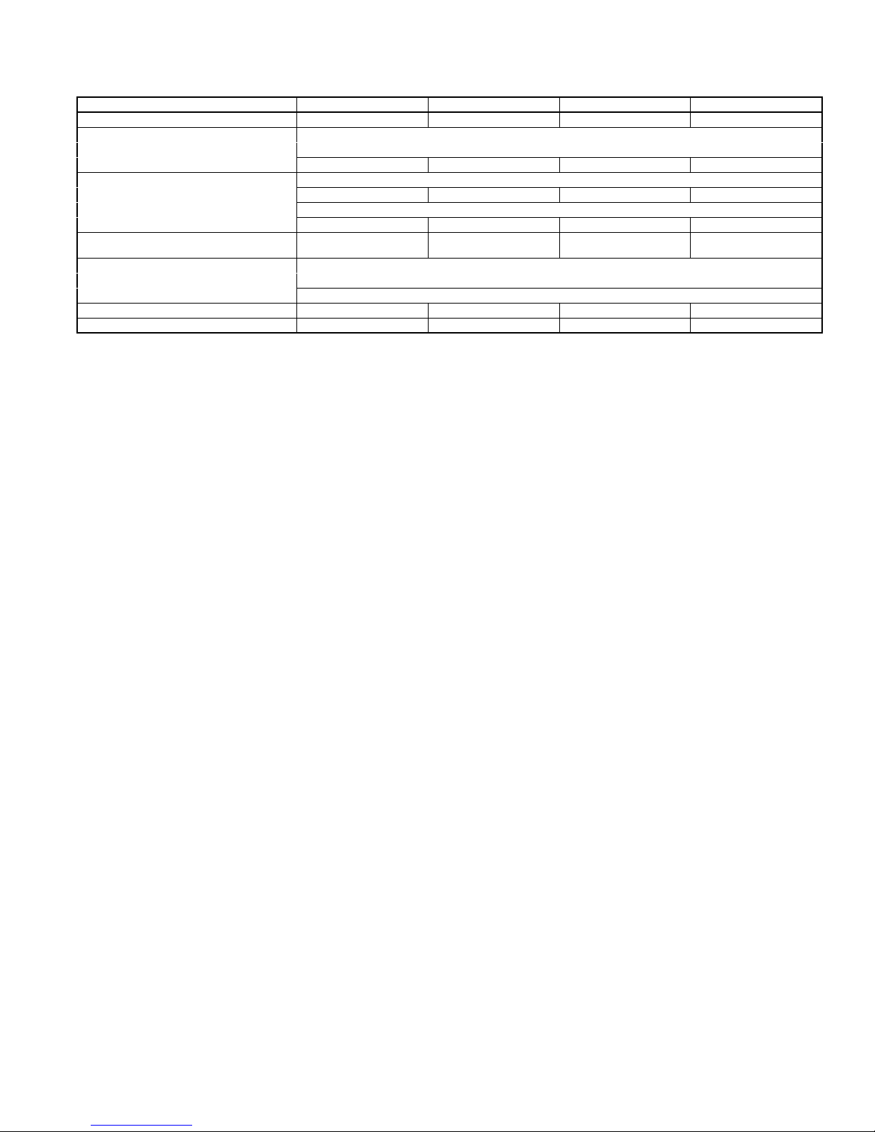
SPECIFICATIONS
MODEL FE4A
SIZE 002 003 005 006*
SHIPPING WEIGHT (Lb) 135 150 172 207
REFRIGERANT Puron (R-410A)
Refr. Metering Device TXV
Size 2 Ton3 Ton4 Ton4 Ton
COIL
Type A Slope A A
Rows - Fins/In. 3 - 14.5
Face Area (sq-ft) 3.46 3.46 5.93 7.42
MATCHES OUTDOOR UNIT SIZES
Nominal Cooling Tons 1.5, 2, 2.5, 3 2, 2.5, 3, 3.5 2.5, 3, 3.5, 4 3, 3.5, 4, 5
FAN
Upflow, Downflow, HorizontalAir Discharge
CFM/TON (Nominal) 350+
MOTOR HP (ECM) 1/2 1/2 1/2 3/4
FILTER 21-1/2 x 16-3/8 21-1/2 x 18-7/8 21-1/2 x 18-7/8 21-1/2 x 23-5/16
* Modular Unit
+ Nominal airflow = outdoor unit size (tons) x 350 cfm. Airflow may be modified by system operating mode.
—3—
Page 4
A02321
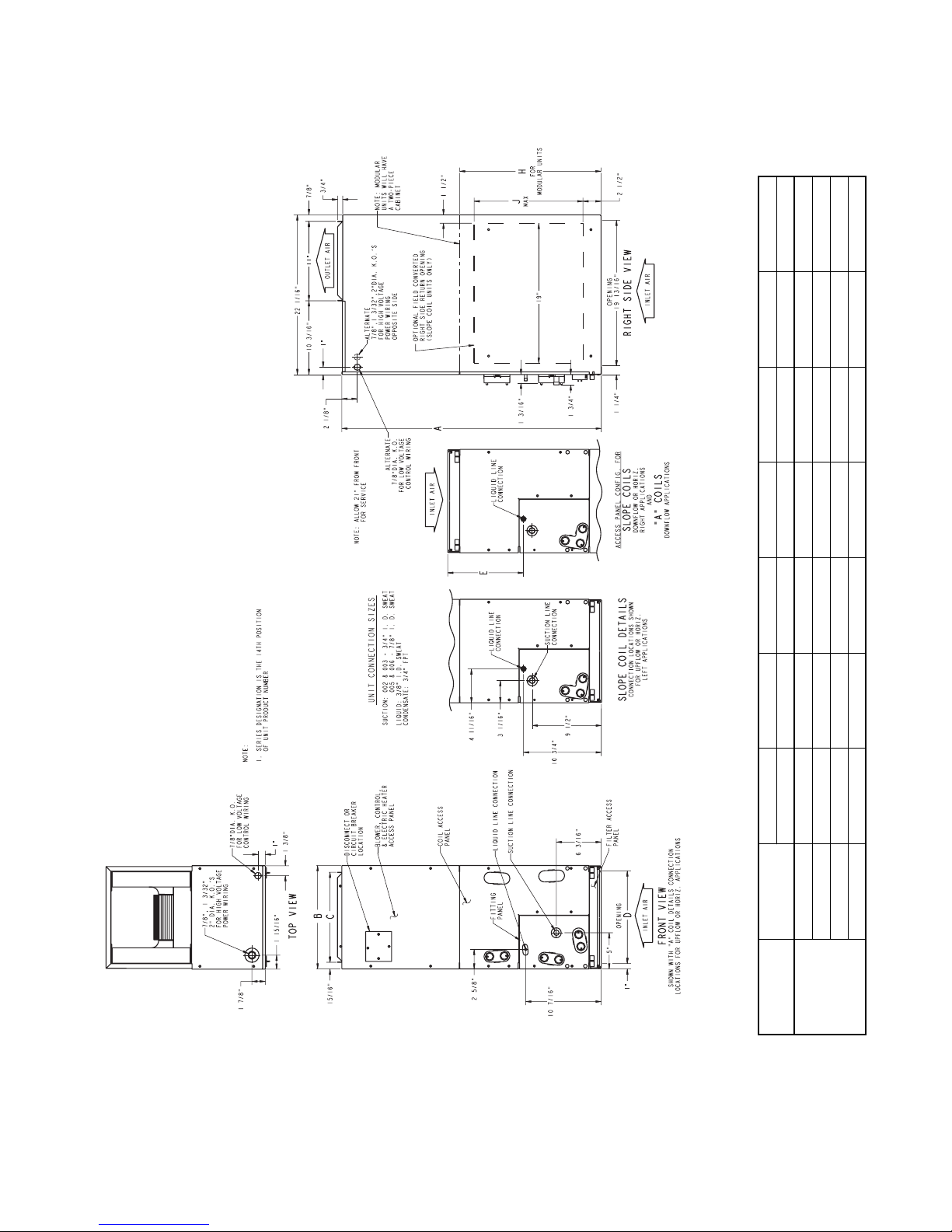
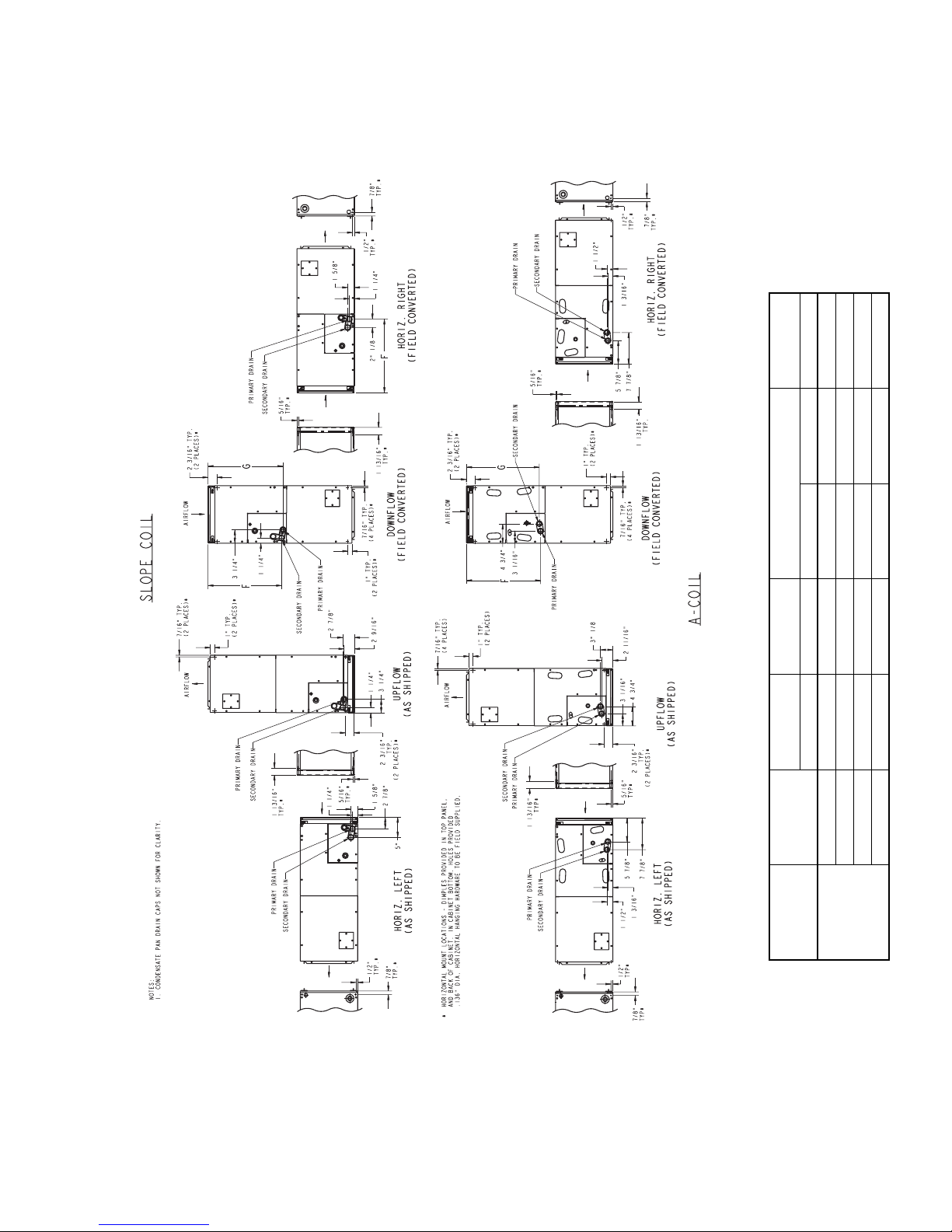
DIMENSIONS
ABCDEH J
In. In. In. In. In. In. In.
002 42-11/16 17-5/8 15-3/4 15-5/8 10-3/4 ——
003 53-7/16 21-1/8 19-1/4 19-1/8 19-3/16 — 19
005 53-7/16 21-1/8 19-1/4 19-1/8 19-1/2 ——
006 59-3/16 24-11/16 22-3/4 22-11/16 25-1/4 34-1/16 —
UNIT SIZE
FE4A
—4—
Page 5
A02322
WEIGHT
SHIPPING
DIMENSIONS Continued
F G COIL CONFIGURATION
In. In. SLOPE “A” Lb
UNIT SIZE
002 18-9/16 18-1/4 — Yes 135
003 26-15/16 27-1/2 Yes — 150
005 27-1/4 26-15/16 — Yes 172
FE4A
006 32-15/16 32-5/8 — Yes 207
—5—
Page 6

PERFORMANCE DATA
AIRFLOW DELIVERY — COOLING, HEATING, ELECTRIC HEATING MODES
The FE4 fan coil will provide airflow at a rate that is requested by
the Integrated System User Interface during Air Conditioning or
Heat Pump Heating (without electric heat) modes. The nominal
airflow for both heating and cooling modes is 350 cfm/ton
nominal refrigeration size of the outdoor unit installed. The
airflow actually requested by the User Interface is modified by its
internal algorithms for zoning, comfort or efficiency concerns.
AIRFLOW PERFORMANCE - AVAILABLE EXTERNAL STATIC PRESSURE
FAN COIL
MODEL AIRFLOW DELIVERY
525 CFM
FE4ANF002
FE4ANF003
FE4ANF005
FE4ANB006
700 CFM
875 CFM
1050 CFM
700 CFM
875 CFM
1050 CFM
1225 CFM
875 CFM
1050 CFM
1225 CFM
1400 CFM
1050 CFM
1225 CFM
1400 CFM
1750 CFM
Refer to the documentation for the User Interface for more
information on how the User Interface controls the fan coil. Safe
operation of electric heaters requires airflow delivery at or above
the minimum CFM for electric heater application listed in the
chart below. The fan coil will adjust its airflow delivery to maintain
safe airflow as operating mode and staging conditions require.
AVAILABLE STATIC
PRESSURE
1.00 IN. H2O
1.00 IN. H2O
1.00 IN. H2O
0.80 IN. H2O
1.00 IN. H2O
1.00 IN. H2O
1.00 IN. H2O
1.00 IN. H2O
1.00 IN. H2O
1.00 IN. H2O
1.00 IN. H2O
1.00 IN. H2O
1.00 IN. H2O
1.00 IN. H2O
1.00 IN. H2O
1.00 IN. H2O
—6—
Page 7

PERFORMANCE DATA Continued
MINIMUM CFM FOR ELECTRIC HEATER APPLICATION
HEAT PUMP
UNIT SIZE
002
003
005
006
NOTE: Heater Only—Air conditioner with electric heater application.
These airflows are the minimum acceptable air flows as U.L. listed.
UNIT
SIZE
Heater Only
018
024
030
036
Heater Only
024
030
036
042
Heater Only
030
036
042
048
Heater Only
036
042
048
060
5 9, 10 15 20 24, 30
625
650
675
850
1000
675
675
850
1025
1150
675
850
1025
1150
1325
1050
1150
1150
1325
1650
650
650
775
950
1050
725
875
950
1075
1200
725
950
1075
1200
1325
1050
1150
1150
1325
1650
CFM
Heater Size KW
825
—
900
1050
1125
850
—
1100
1150
1300
850
1100
1150
1300
1400
1050
1350
1350
1400
1650
1025
—
—
1125
1225
1100
—
1150
1275
1400
1100
1150
1275
1400
1500
1100
1350
1575
1600
1750
—
—
—
—
—
—
—
—
—
—
1400
—
—
—
1600
1750
—
—
1750
1750
—7—
Page 8

0.7
0.6
0.5
0.4
ACCEPTABLE RANGE
0.3
0.2
SUPPLY STATIC PRESSURE, IN.W.C.
TOO HIGH
RETURN STATIC
PRESSURE
(DIFFICULT TO MAKE
TRAP)
0.1
0
0
0.1 0.2 0.3 0.4 0.5 0.6
RETURN STATIC PRESSURE, IN.W.C.
A96052
Acceptable Duct Conditions
For satisfactory operation (specifically making dry secondary trap), subject fan coils must be installed with duct systems which fall
within the “Acceptable Range” illustrated above.
—8—
Page 9

EVAPORATOR
UNIT
SIZE
002
003
005
006
See notes on page 10.
AIR
Cfm
500 40 32 26 36 28 22 32 24 18 27 19 14 21 13 11
0.04
650 50 40 32 45 36 27 39 30 22 33 24 18 26 17 14
0.07
875 58 49 38 53 42 32 46 35 27 39 28 22 31 20 18
0.10
1000 62 51 41 56 45 35 50 38 29 42 30 24 33 22 20
0.11
1250 67 55 45 61 49 39 54 42 33 46 34 28 37 25 24
0.13
800 59 48 38 53 42 32 46 35 24 39 27 20 30 18 16
0.20
1000 68 56 45 61 49 37 54 41 29 45 32 25 35 22 20
0.22
1200 75 62 49 68 54 42 60 45 34 50 36 29 40 25 23
0.25
1400 80 67 54 73 59 46 64 49 38 54 39 32 43 28 27
0.27
750 61 49 39 55 43 33 48 37 27 41 29 20 33 21 17
0.04
950 74 60 48 67 53 40 59 45 33 50 35 25 39 24 21
0.06
1150 89 72 57 79 63 48 69 52 38 58 41 31 44 29 25
0.07
1500 103 84 66 92 73 56 81 61 46 67 48 39 52 34 31
0.10
1700 110 89 71 99 78 60 86 65 49 72 51 42 56 37 35
0.11
1050 77 62 50 69 55 43 61 47 35 52 38 27 41 27 22
0.01
1300 100 82 65 90 71 55 79 60 45 66 47 37 49 32 27
0.02
1750 117 96 77 106 84 65 93 71 53 78 56 46 60 40 34
0.04
2050 126 103 83 114 91 71 99 76 59 84 60 50 65 44 39
0.05
2300 132 108 87 119 95 75 105 80 63 88 63 54 70 47 42
0.06
BF
PERFORMANCE DATA Continued
COOLING CAPACITIES (MBtuh)
COIL REFRIGERANT TEMPERATURE (°F)*
35 40 45 50 55
Evaporator Air — Entering Wet-Bulb Temperature (°F)
72 67 62 72 67 62 72 67 62 72 67 62 72 67 62
18 18 19 16 16 17 14 14 15 12 12 13 10 10 11
21 22 23 19 20 21 16 17 18 14 15 16 12 13 14
24 26 28 22 24 25 19 21 22 17 19 19 15 16 18
26 28 31 23 26 28 21 23 25 18 20 21 16 18 20
29 33 36 27 30 33 24 27 30 22 24 26 19 21 24
28 29 31 25 27 28 22 23 24 19 20 20 16 16 16
32 34 37 29 31 33 26 28 28 23 24 25 19 20 20
35 39 42 32 36 38 29 32 33 26 28 29 22 23 23
38 43 47 35 39 43 32 36 37 28 32 32 24 26 27
27 27 28 24 25 25 21 22 22 18 18 18 15 15 15
32 34 35 29 30 31 25 26 27 22 23 23 18 18 19
37 39 41 33 35 36 29 31 32 25 26 27 20 22 22
43 46 49 38 41 44 34 37 39 29 32 33 25 27 27
45 50 53 41 45 48 36 39 42 31 34 36 27 29 30
34 36 37 31 32 33 27 28 29 23 25 24 20 20 20
42 45 47 37 40 42 33 35 37 29 31 32 23 25 24
48 53 57 44 48 52 39 43 46 34 38 39 29 31 31
52 58 63 48 53 57 43 47 51 37 42 43 33 35 35
55 62 68 50 57 61 45 51 54 40 45 46 35 39 38
—9—
Page 10

* Saturated suction leaving evaporator coil.
Sensible Heat Capacity (1000 Btuh)
Gross Cooling Capacity (1000 Btuh)
BF—Bypass Factor
NOTES:
1. Net capacities shown include a deduction for evaporator fan motor heat.
2. Contact manufacturer for cooling capacities at conditions other than
shown in table.
3. Formulas:
Leaving db = entering db —
Leaving wb = wb corresponding to enthalpy of air leaving coil (h
= h
h
lwb
ewb
where h
ewb
4. Direct interpolation is permissible. Do not extrapolate.
total capacity (Btuh)
—
= enthalpy of air entering coil.
4.5 x CFM
sensible heat cap.
1.09 x CFM
lwb
)
5. SHC is based on 80°F db temperature of air entering coil. Below 80°F
subtract (corr factor x CFM) from SHC.
Above 80°F db, add (corr factor x CFM) to SHC.
SHC CORRECTION FACTOR
ENTERING AIR DRY-BULB TEMP (°F)
79 78 77 76 75 Under 75
BYPASS
FACTOR
0.10
0.20
0.30
Interpolation is permissible.
Correction Factor = 1.09 x (1 – BF) x (db – 80)
81 82 83 84 85 Over 85
Correction Factor
0.98
1.96
2.94
3.92
4.91
0.87
0.76
1.74
1.53
2.62
2.29
3.49
3.05
4.36
3.82
Use formula
shown below
PERFORMANCE DATA Continued
ESTIMATED SOUND POWER LEVEL (dBA)*
UNIT
SIZE
FE4-002
FE4-003
FE4-005
FE4-006
* Estimated sound power levels have been derived using the method described in the 1987 ASHRAE Systems & Applications Handbook, chapter 52, p. 52.7.
CFM — Cubic Ft per Minute
ESP — External Static Pressure
RPM — Revolutions per Minute
CONDITIONS OCTAVE BAND CENTER FREQUENCY
CFM ESP 63 125 250 500 1000 2000 4000
400 0.25 63.0 59.0 55.0 52.0 50.0 48.0 44.0
600 0.25 64.7 60.7 56.7 53.7 51.7 49.7 45.7
800 0.25 66.0 62.0 58.0 55.0 53.0 51.0 47.0
1000 0.25 67.0 63.0 59.0 56.0 54.0 52.0 48.0
1200 0.25 67.8 63.8 59.8 56.8 54.8 52.8 48.8
1400 0.25 68.4 64.4 60.4 57.4 55.4 53.4 49.4
1400 0.25 63.0 59.0 55.0 52.0 50.0 48.0 44.0
1600 0.25 64.7 60.7 56.7 53.7 51.7 49.7 45.7
1800 0.25 66.0 62.0 58.0 55.0 53.0 51.0 47.0
1000 0.25 67.0 63.0 59.0 56.0 54.0 52.0 48.0
1200 0.25 67.8 63.8 59.8 56.8 54.8 52.8 48.8
1400 0.25 68.4 64.4 60.4 57.4 55.4 53.4 49.4
636 0.25 65.0 61.0 57.0 54.0 52.0 50.0 46.0
400 0.25 63.0 59.0 55.0 52.0 50.0 48.0 44.0
600 0.25 64.7 60.7 56.7 53.7 51.7 49.7 45.7
800 0.25 66.0 62.0 58.0 55.0 53.0 51.0 47.0
1000 0.25 67.0 63.0 59.0 56.0 54.0 52.0 48.0
1200 0.25 67.8 63.8 59.8 56.8 54.8 52.8 48.8
1400 0.25 68.4 64.4 60.4 57.4 55.4 53.4 49.4
1600 0.25 69.0 65.0 61.0 58.0 56.0 54.0 50.0
600 0.25 64.7 60.7 56.7 53.7 51.7 49.7 45.7
800 0.25 66.0 62.0 58.0 55.0 53.0 51.0 47.0
1000 0.25 67.0 63.0 59.0 56.0 54.0 52.0 48.0
1200 0.25 67.8 63.8 59.8 56.8 54.8 52.8 48.8
1400 0.25 68.4 64.4 60.4 57.4 55.4 53.4 49.4
1600 0.25 69.0 65.0 61.0 58.0 56.0 54.0 50.0
1800 0.25 69.5 65.5 61.5 58.5 56.5 54.5 50.5
2000 0.25 70.0 66.0 62.0 59.0 57.0 55.0 51.0
2150 0.25 70.3 66.3 62.3 59.3 57.3 55.3 51.3
—10—
Page 11

PERFORMANCE DATA Continued
AIRFLOW PERFORMANCE CORRECTION FACTORS
The FE4A Airflow Performance table was developed using fan coils with 10-kw electric heaters (2 elements) in the units. For fan coils
with heaters made up of a different number of elements, the external available static at a given CFM from the table may be corrected
by adding or subtracting pressure. Use table for correction.
STATIC PRESSURE
CORRECTION (in. wc)
HEATER KW ELEMENTS
0 0 +.02 +.03
5 1 +.01 +.02
8, 10 2 0 0
9, 15 3 –.02 –.03
20 4 –.04 –.06
18, 24, 30 6 –.06 –.10
FACTORY-INSTALLED FILTER STATIC PRESSURE DROP (In. wc)
Sizes 002–005 Size 006
MODEL
FE4A
002 0.020 0.044 0.048 0.072 0.100 ————
003 — 0.020 0.035 0.051 0.070 0.092 ———
005 ——0.035 0.051 0.070 0.092 0.120 ——
006 ————0.070 0.092 0.120 0.152 0.187
400 600 800 1000 1200 1400 1600 1800 2000
CFM
AIR DELIVERY PERFORMANCE CORRECTION COMPONENT PRESSURE DROP (IN. WC)
AT INDICATED AIRFLOW (DRY TO WET COIL)
MODEL
FE4A
002 0.012 0.016 0.022 0.028 0.034 0.040 0.049 ——— —
003 — 0.026 0.034 0.042 0.052 0.063 0.075 0.083 0.091 0.098 0.110
005 — 0.006 0.008 0.010 0.012 0.015 0.017 0.020 0.023 0.027 0.030
006 0.013 0.016 0.018 0.020 0.023 0.027 0.030 0.034 0.039 0.044 0.048
NOTE: Subtract the above pressure drop corrections from unit airflow data when that component or condition is used. The remaining external static pressure
will be available for the duct system.
600 700 800 900 1000 1100 1200 1300 1400 1500 1600
1100 1200 1300 1400 1500 1600 1700 1800 1900 2000 2100
CFM
CFM
—11—
Page 12

1.
ACCESSORY LIST
ITEM ACCESSORY PART NO. FAN COIL SIZE USED WITH FE4A
Disconnect Kit KFADK0201DSC Cooling controls and heaters through 10-kW
Downflow Conversion Kit (Slope) KFADC0201SLP 003
Downflow Conversion Kit (A-coil) KFADC0401ACL 002, 005, 006
Downflow Base Kit KFACB0201CFB 002
KFACB0301CFB 003, 005
KFACB0401CFB 006
Filter Kit (12 Pack) KFAFK0212MED 002
KFAFK0312LRG 003, 005
KFAFK0412XXL 006
Single-Point Wiring Kit KFASP0101SPK Only with 15- and 20-kW Fused Heaters
Airflow Sensor Kit (Air Cleaner) KEAAC0101AAA All
Air Cleaner 240-Volt Conversion Kit KEAVC0201240 All
PVC Condensate Drain Trap Kit (50 Pack) KFAET0150ETK All
Downflow/Horizontal Conversion Gasket Kit KFAHD0101SLP All
ACCESSORY KITS DESCRIPTION
SUGGESTED AND REQUIRED USE
Disconnect Kit
The kit is used to disconnect electrical power to the fan coil so service or maintenance may be performed safely.
SUGGESTED USE: FE4 units with 3- through 10-kW electric resistance heaters and cooling controls.
2. Downflow Conversion Kit
Fan coils are shipped from the factory for upflow or horizontal-left applications. Downflow conversion kits provide proper condensate water
drainage and support for the coil when used in downflow applications. Separate kits are available for slope coils and A-coils.
REQUIRED USE: This kit must be used whenever FE4 fan coils are used in downflow applications.
3. Downflow Base Kit
This kit is designed to provide a 1-in. minimum clearance between unit discharge plenum, ductwork, and combustible materials. It also provides
a gap free seal with the floor.
REQUIRED USE: This kit must be used whenever FE4 fan coils are used in downflow applications.
4. Single-Point Wiring Kit
The single-point wiring kit acts as a jumper between L1 and L3 lugs, and between L2 and L4 lugs. This allows the installer to run 2 heavy-gage,
high-voltage wires into the fan coil rather than 4 light-gage, high-voltage wires.
SUGGESTED USE: FE4 fan coils with 15- and 20-kW fused heaters only.
5. Air Cleaner 240-Volt Conversion Kit
The AIRA electronic air cleaner comes ready for 115-v operation.
REQUIRED USE: This kit is required when running 240-volt circuit to air cleaner.
6. Airflow Sensor Kit (Air Cleaner)
The airflow sensor kit ensures the FE4 fan coil and electronic air cleaner work as a system.
REQUIRED USE: This kit is required whenever an electronic air cleaner is used with an FE4 fan coil.
7. Fan Coil Filter
Kit shipped from factory with 12 fan coil framed filters. These filters collect large dust particles from the return air entering the fan coil and prevents
them from collecting on the coil. This process helps to keep the coil clean, which increases heat transfer and in turn the efficiency of the system.
SUGGESTED USE: For replacing factory-supplied filters (same filters).
8. Condensate Drain Trap Kit
This kit consists of 50 PVC condensate traps. Each trap is pre-formed and ready for field installation. This deep trap helps the system make and
hold proper condensate flow even during blower initiation.
SUGGESTED USE: FE4 fan coils.
9. Downflow/Horizontal Conversion Gasket Kit
This kit provides the proper gasketing of units when applied in either a Downflow or Horizontal application.
REQUIRED USE:
FE4 fan coils.
—12—
Page 13

ELECTRICAL DATA
UNITS WITHOUT ELECTRIC HEATER
UNIT
SIZE VOLTS-PHASE FLA
002 208/230-1 4.3 5.4 14 15
003 208/230-1 4.3 5.4 14 15
005 208/230-1 4.3 5.4 14 15
006 208/230-1 6.8 8.5 14 15
* Use copper wire only to connect unit. If other than uncoated (nonplated) 75°F ambient, copper wire (solid wire for 10 AWG and smaller, stranded wire for
larger than 10 AWG) is used consult applicable tables of the National Electric Code (ANSI/NFPA 70).
NOTE: If branch circuit wire length exceeds 100 ft, consult NEC 210-19a to determine maximum wire length. Use 2% voltage drop.
FLA — Full Load Amps
MIN
CKT
AMPS
Min Wire
Size Awg*
BRANCH CIRCUIT
Fuse/Ckt Bkr
Amps
ACCESSORY ELECTRIC HEATERS
ELECTRIC HEATERS
HEATER
PART NO.
KFCEH0501N05 5 230/1 5 None All 15,700 —
KFCEH0901N10 10 230/1 10 None All 31,400 —
KFCEH3001F15 15 230/1 5, 15 Fuses** All 47,100 5, 10, 15
KFCEH3201F20 20 230/1 5, 20 Fuses** All 62,800 5, 10, 15, 20
KFCEH2901N09 9 230/1* 3, 9 None All 28,300 3, 6, 9
KFCEH1601315 15 230/3 5, 15 None All 47,100 —
KFCEH3401F24 24 230/3† 8, 16, 24 Fuses 005, 006 78,500 8, 16, 24
KFCEH3501F30 30 230/3† 10, 20, 30 Fuses 005, 006 94,200 10, 20, 30
KFCEH2401C05 5 230/1 5 Ckt Bkr All 15,700 —
KFCEH2601C10 10 230/1 10 Ckt Bkr All 31,400 —
KFCEH3101C15 15 230/1 5, 15 Ckt Bkr All 47,100 5, 10, 15
KFCEH3301C20 20 230/1 5, 20 Ckt Bkr All 62,800 5, 10, 15, 20
* Field convertable to 3 phase.
† These heaters field convertable to single phase.
‡ Blower motor heat not included.
** Single point wiring kit required for these heaters in Canada.
KW
@ 240V VOLTS/PHASE
STAGES (KW
OPERATING)
INTERNAL
CIRCUIT
PROTECTION
FAN COIL SIZE
USED WITH
HEATING CAP.
@230V‡
INTELLIGENT
HEAT
CAPABLE (KW
OPERATING)
HEATER KW PHASE
51— 1/60
81— 1/60
9 1/3 ——
10 1 — 1/60
15 1 2/30, 2/60 2/60
15 3 ——
18 3 ——
20 1 4/60 2/60
24 3/1 6/60 —
30 3/1 6/60 —
* All circuit breakers are 2 pole.
ELECTRIC HEATER INTERNAL PROTECTION
FUSES
QTY/SIZE
—13—
CKT BKR *
QTY/SIZE
Page 14

Dual Circuit
208/230V (FT)‡‡
MAX WIRE LENGTH
Single
Circuit
Dual Circuit
208/230V
MAX FUSE/CKT BKR AMPS
Single
Circuit
Dual Circuit
208/230V
BRANCH CIRCUIT
MIN GND WIRE SIZE
Single
Circuit
208/230V (FT)‡‡
MAX WIRE LENGTH
208/230V
MAX FUSE/CKT BKR AMPS
208/230V
MIN GND
WIRE SIZE
Dual Circuit
208/230V††
MIN WIRE SIZE (AWG)
Single
Circuit
Electric Heater Electrical Data
Dual Circuit
208/230V**
MIN AMPACITY
Single
Circuit
Dual Circuit
208/230V
HEATER AMPS
Single
Circuit
CIRCUIT
INTERNAL
PROTECTION
PHASE
208/230V††
MIN WIRE SIZE (AWG)
208/230V**
MIN AMPACITY
Field Multipoint Wiring of 24-and 30-kW Single Phase
208/230V
HEATER AMPS
PHASE
KW
HEATER
3 2.3 1 None 10.9/12.0 ——15.9/17.3 ——12/12 ——12/12 ——20/20 ——67/68 ——
240v 208v L1,L2 L3,L4 L1,L2 L3,L4 L1,L2 L3,L4 L1,L2 L3,L4 L1,L2 L3,L4 L1,L2 L3,L4
PART NO.
KFCEH0401N03
5 3.8 1 None 18.1/20.0 ——26.0/28.4 ——10/10 ——10/10 ——30/30 ——66/66 ——
5 3.8 1 None 18.1/20.0 ——31.2/33.5 ——8/8 ——10/10 ——35/35 ——85/88 ——
1
2
1
KFCEH0501N05
KFCEH0501N05
9 6.8 3 None 18.8/20.8 ——32.0/34.5 ——8/8 ——10/10 ——35/35 ——83/85 ——
5 3.8 1 Ckt Bkr 18.1/20.0 ——26.0/28.4 ——10/10 ——10/10 ——30/30 ——66/66 ——
5 3.8 1 Ckt Bkr 18.1/20.0 ——31.2/33.5 ——8/8 ——10/10 ——35/35 ——85/88 ——
9 6.8 1 None 32.8/36.0 ——49.5/53.5 ——8/6 ——10/10 ——50/60 ——54/87 ——
2
KFCEH2401C05
KFCEH0901N10 10 7.5 1 None 36.2/40.0 ——53.8/58.5 ——6/6 ——10/10 ——60/60 ——78/80 ——
KFCEH2401C05
KFCEH2901N09***‡
KFCEH3001F15*** 15 11.3 1 Fuse 54.2/59.9 36.2/40.0 18.1/20.0 76.3/83.4 53.8/58.5 22.7/25.0 4/4 6/6 10/10 8/8 10/10 10/10 80/90 60/60 25/25 88/89 78/80 75/76
KFCEH3101C15*** 15 11.3 1 Ckt Bkr — 36.2/40.0 18.1/20.0 — 53.8/58.5 22.7/25.0 — 6/6 10/10 — 10/10 10/10 — 60/60 25/25 — 78/80 75/76
KFCEH2701C15*** 15 11.3 1 Ckt Bkr — 36.2/40.0 18.1/20.0 — 53.8/58.5 22.7/25.0 — 6/6 10/10 — 10/10 10/10 — 60/60 25/25 — 78/80 75/76
KFCEH1601315 15 11.3 3 None 31.3/34.6 ——47.7/51.8 ——8/6 ——10/10 ——50/60 ——56/90 ——
KFCEH3201F20*** 20 15.0 1 Fuse 72.3/79.9 36.2/40.0 36.2/40.0 98.9/108.4 53.8/58.5 45.3/50.0 3/2 6/6 8/8 8/6 10/10 10/10 100/110 60/60 50/50 85/109 78/80 59/59
KFCEH2601C10 10 7.5 1 Ckt Bkr 36.2/40.0 ——53.8/58.5 ——6/6 ——10/10 ——60/60 ——78/80 ——
24 18.0 1 Fuse 86.7/95.5 ——116.9/127.9 ——1/1 ——6/6 ——125/150 ——115/116 ——
24 18.0 3 Fuse 50.1/55.4 ——71.2/77.8 ——4/4 ——8/8 ——80/80 ——94/95 ——
KFCEH3301C20*** 20 15.0 1 Ckt Bkr — 36.2/40.0 36.2/40.0 — 53.8/58.5 45.3/50.0 — 6/6 8/8 — 10/10 10/10 — 60/60 50/50 — 78/80 59/59
KFCEH2801C20*** 20 15.0 1 Ckt Bkr — 36.2/40.0 36.2/40.0 — 53.8/58.5 45.3/50.0 — 6/6 8/8 — 10/10 10/10 — 60/60 50/50 — 78/80 59/59
KFCEH3401F24†***
—14—
30 22.5 3 Fuse 62.6/69.2 ——86.8/95.0 ——3/3 ——8/8 ——90/100 ——97/98 ——
30 22.5 1 Fuse 109.0/120.0 ——144.8/158.5 ——0/00 ——6/6 ——150/175 ——117/150 ——
KFCEH3501F30†***
KW
HEATER PART NO.
240V 208V L1,L2 L3,L4 L5,L6 L1,L2 L3,L4 L5,L6 L1,L2 L3,L4 L5,L6 L1,L2 L3,L4 L5,L6 L1,L2 L3,L4 L5,L6
† Field convertible to 1 phase, single or multiple supply circuit.
KFCEH3501F30†*** 30 22.5 1 36.2/40.0 36.2/40.0 36.2/40.0 53.8/58.5 45.3/50.0 45.3/50.0 6/6 8/8 8/8 10/10 60/60 50/50 50/50 78/80 59/59 59/59
‡ Field convertible to 3 phase.
KFCEH3401F24†*** 24 18.0 1 28.9/32.0 28.9/32.0 28.9/32.0 44.7/48.5 36.2/40.0 36.2/40.0 8/8 8/8 8/8 10/10 45/50 40/40 40/40 59/60 73/73 73/73
1. For fan coil sizes 018-036.
2. For fan coil sizes 042-060 and all FE4A sizes.
3. Single circuit application of F15 and F20 heaters requires single-point wiring kit accessory.
(ANSI/NFPA 70).
** Includes blower motor amps of largest fan coil used with heater.
†† Copper wire must be used. If other than uncoated (non-plated), 75°C ambient, copper wire (solid wire for 10 AWG and smaller, stranded wire for larger than 10 AWG) is used, consult applicable tables of the National Electric Code
‡‡ Length shown is as measured 1 way along wire path between unit and service panel for a voltage drop not to exceed 2%.
*** Heaters are Intelligent Heat capable
NOTES:
Page 15

—15—
Page 16

HEAT PUMP
MATCHED SYSTEM
VENTILATOR PLUS
ZONE PERFECT
PLUS
™
EQUIPMENT CONTROLLER
HUMIDIFIER
FAN COIL
ELECTRONIC
AIR CLEANER
A02295
© 2003 Bryant Heating & Cooling Systems, 7310 W. Morris St. Indpls., IN 46231 PRINTED IN U.S.A. Catalog No. 12FE-4A0 12-03
—16—
SPECIFICATIONS SUBJECT TO CHANGE WITHOUT NOTICE
UNIT MUST BE INSTALLED IN ACCORDANCE
WITH INSTALLATION INSTRUCTIONS
Cancels: New
Form PDS FE4A.18.1
 Loading...