

Page 1
SYSTXBBUIZ01--B
EVOLUTIONt CONTROL
Installation Instructions
HOLD
E
VOLUTION™ SYSTEM
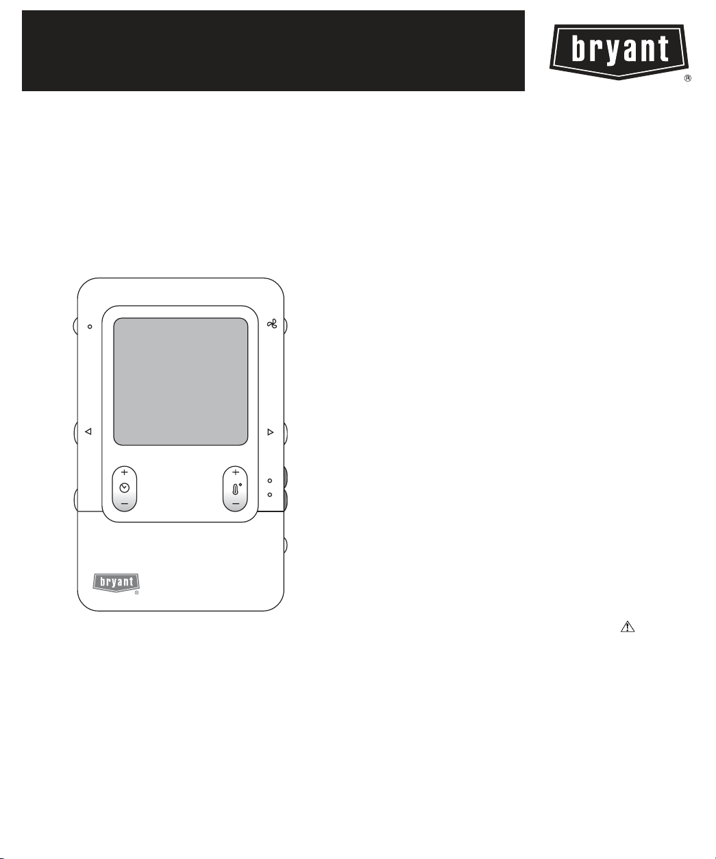
Fig. 1 -- Evolution
t Zone Control
HEAT
COOL
OFF
A04032
NOTE: Read the entire instruction manual before starting the
installation.
TABLE OF CONTENTS
PAGE
SAFETY CONSIDERATIONS 1.........................
INTRODUCTION 2...................................
INSTALLATION AND START--UP OVERVIEW 2..........
INSTALLATION 2....................................
INSTALLING EVOLUTION ZONE CONTROL 5...........
INITIAL POWER--UP 6................................
QUICK START 8.....................................
INSTALL / SERVICE MENUS 9.........................
EQUIPMENT SUMMARY MENU 9......................
INSTALL MENU 9....................................
SETUP MENU 9......................................
CHECKOUT MENUS 13...............................
SERVICE MENUS 14..................................
OPERATIONAL INFORMATION 16.....................
TROUBLESHOOTING 18..............................
SYSTEM MALFUNCTION SCREEN 19..................
SAFETY CONSIDERATIONS
Read and follow manufacturer instructions carefully. Follow all
local electrical codes during installation. All wiring must conform
to local and national electrical codes. Improper wiring or
installation may damage the Evolution Zone System. Recognize
safety information. This is the safety--alert symbol
see this symbol on the equipment and in the instruction manual, be
alert to the potential for personal injury. Understand the signal
words DANGER, WARNING, and CAUTION.
These words are used with the safety--alert symbol. DANGER
identifies the most serious hazards, which will result in severe
personal injury or death. WARNING signifies a hazard, which
could result in personal injury or death. CAUTION is used to
identify unsafe practices, which may result in minor personal
injury or product and property damage. NOTE is used to highlight
suggestions which will result in enhanced installation, reliability, or
operation.
. When you
Page 2
INTRODUCTION
The Evolution Zone System consists of several intelligent
communicating components which includes the Evolution Zone
Control (or User Interface), Smart Sensors, Damper Control
Module, variable speed furnace or FE fan coil, 2--stage AC or HP
and Evolution Packaged Products, which continually communicate
with each other via a four--wire connection called the ABCD bus.
Commands, operating conditions, and other data are passed
continually between components over the ABCD bus. The result is
a new level of comfort, versatility, and simplicity.
All Evolution furnaces or fan coils are variable--speed and
multi--stage for maximum flexibility, efficiency, and comfort. They
support controlled ventilation, humidification, dehumidification,
and air quality control. Either an Evolution 2--stage
(communicating), or a standard 24VAC controlled outdoor unit
may be used.
When using conventional outdoor units, the Evolution furnace or
fan coil provides the 24 volt signals needed to control them. Also,
the Evolution Damper Control Module (P/N SYSTXBB4ZC01)
allows connection of a Bryant HRV or ERV without the need for a
separate wall control.
All system components are controlled through the wall mounted
BBUIZ01--B
Evolution Zone Control, which replaces the conventional
thermostat and provides the homeowner with a single wall control
for all features of the system.
Design Considerations
The Evolution Zone system is unique because a bypass damper
must not be used. This is possible due to the intelligence of the
system and variable speed motor technology. For trouble--free
applications, the following parameters should always be met:
1. Zones should be sized so that each zone can deliver at least
the minimum airflow for the system in both heating and
cooling modes.
2. Oversize duct work by 25% to avoid excess noise at minimum zone airflow.
3. Be aware that heating airflow may be higher than cooling
airflow depending on equipment combination.
INSTALLATION AND START--UP
OVERVIEW
This instruction covers installation of the Evolution Zone Control
only. Physical installation instructions for the indoor and outdoor
equipment, Damper Control Module, and accessories are provided
with each unit.
Setup, commissioning, operation, and troubleshooting of the
Evolution Zone System are covered in this installation instruction.
It is the guide to connecting the system components and
commissioning the system once all physical components are
installed. Special screen prompts and start--up capabilities are
provided in the Evolution System to simplify and automate the
initial commissioning of the system.
S Install Evolution Zone Control according to this instruc-
tion.
S Install indoor unit, outdoor unit, and accessories accord-
ing to their instructions.
S Wire complete system according to this instruction.
S Setup, commission, and operate system according to this
instruction to assure a smooth and trouble free start--up.
INSTALLATION
Check Equipment and Job Site
Inspect equipment. File claim with shipping company prior to
installation if shipment is damaged or incomplete.
Evolution Zone Control Location and Wiring
Considerations
!
WARNING
ELECTRICAL OPERATION HAZARD
Failure to follow this warning could result in personal injury
or death.
Disconnect power before routing control wiring.
All wiring must comply with national, local, and state codes.
Evolution Zone Control
The Evolution Zone Control User Interface is the command center
for the Evolution Zone System and is typically located in Zone 1 to
sense and control temperature in this zone. It should be located
where it is easily accessible and visible to the adult homeowner or
end user.
For accurate temperature measurement, the following guidelines
should be followed:
The Evolution Zone Control and Room Sensors should be
mounted:
S Approximately 5 feet (1.5 meters) from the floor.
S Close to or in a frequently used room, preferably on an
inside partitioning wall.
S On a section of wall without pipes or ductwork.
The Evolution Zone Control and Room Sensors should NOT be
mounted:
S Close to a window, on an outside wall, or next to a door
leading to the outside.
S Exposed to direct light or heat from a lamp, sun, fire-
place, or other temperature--radiating objects which
could cause a false reading.
S Close to or in direct airflow from supply registers.
S In areas with poor air circulation, such as behind a door
or in an alcove.
Remote Room Sensor
A Remote Room Sensor can be used with the Evolution Zone
Control to take the place of the User Interface internal temperature
sensor. This allows the Evolution Zone Control to be mounted in
areas with less than optimal airflow (such as near an exterior door,
window or in a closet). The remote sensor can be wired to the
terminal block connectors labeled S1 and S2 at the User Interface
backplate, or the OS1 and OS1C connection at the Damper Control
Module. In either case, the Evolution Zone Control will
automatically detect the Remote Room Sensor and ignore its
internal temperature sensor. It is also important to note the
humidity sensor cannot be remotely located, so do not locate the
Evolution Zone Control in an area where humidity sensing may
not be accurate.
NOTE: S1 & S2 connection on User Interface backplate is now
used for Remote Room Sensor, NOT for OAT Sensor hookup.
In addition, the Remote Room Sensor is a temperature sensor only,
having no additional user inputs. This sensor is typically connected
to the Damper Control Module and used to sense and control
temperature in each zone.
Location
Option
2
Page 3
Remote Sensor A
veraging
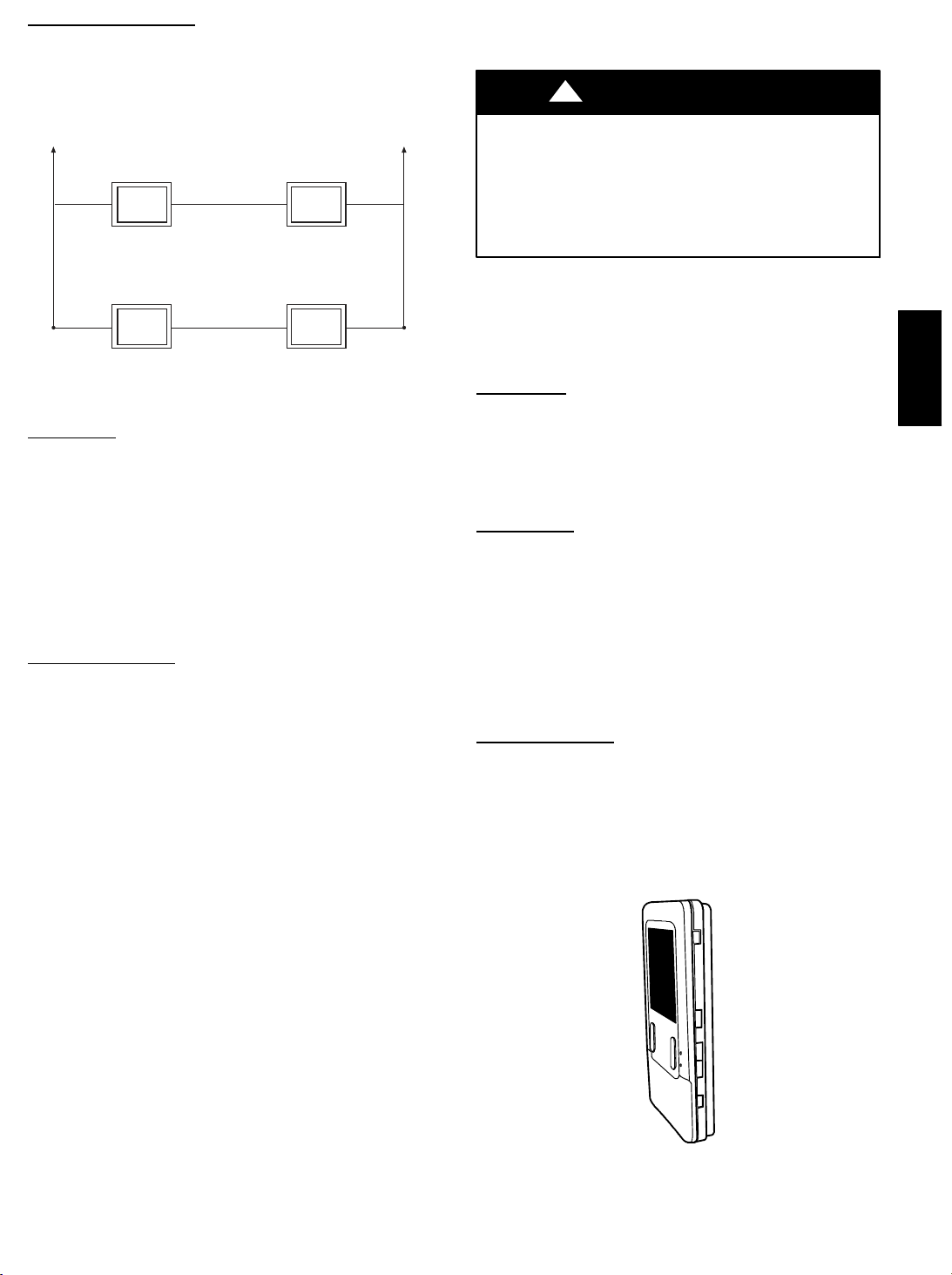
Typically, one Remote Room Sensor is used per zone, but multiple
sensors may be used and averaged in some applications. Averaging
requires a special series--parallel wiring method with a specific
number of sensors. See Fig. 2 in this manual for wiring diagram.
Damper Control
Module
ZS_
Sensor 1 Sensor 2
Sensor 3 Sensor 4
Damper Control
Module
ZS_C
A03233
Fig. 2 -- Remote Room Sensor -- Parallel Wiring
Smart
Sensor
Any zone may use a Smart Sensor. It provides a temperature
display and buttons to adjust the desired temperature in that zone
only. It also displays outdoor temperature and indoor humidity
sensed at the User Interface. Only one Smart Sensor may be used
per zone. They cannot be averaged like Remote Room Sensors. If a
Smart Sensor is used in a zone, a Remote Room Sensor may also
be used in the same zone. The Remote Room Sensor has priority
over the Smart Sensor. The Smart Sensor will display the Remote
Room Sensor temperature.
NOTE: Smart Sensors must be addressed to identify which zone it
will control. See Smart Sensor Installation Instructions for details.
Considerations
Wiring
Ordinary thermostat wire is recommended. Use 22 AWG or larger
for normal wiring applications. Continuous wire lengths over 100
ft. should use 20 AWG or larger.
NOTE: ABCD bus wiring only requires a four--wire connection;
however, it is good practice to run thermostat cable having more
than four wires in the event of a damaged or broken wire during
installation.
Each communicating device in the Evolution Zone System has a
four--pin connector labeled ABCD. It is recommended that the
following color code be used when wiring each device:
A — Green = Data A
B — Yellow = Data B
C — White = 24VAC (Com)
D — Red = 24VAC (Hot)
It is not mandatory that the above color code be used, but each
ABCD connector in the system MUST be wired consistently.
Locating Damper Control Module
All wiring is run back to the Damper Control Module. Select a
location near the furnace or fan coil where wiring from the User
Interface, each Remote Room Sensor or Smart Sensor, each
damper actuator, and the equipment itself can come together easily.
The Damper Control Module is approved for indoor use only and
should never be installed with any of its components exposed to
the elements. The Damper Control Module (and zone dampers)
may be installed in any area where the temperature remains
between --4_F to 158_F(--20_Cto70_C), and there is no
condensation. The cover must be installed to prevent damage from
other sources. Do not locate where it will be accessible to children.
It may be mounted in either vertical or horizontal position.
Remember that wiring access is likely the most important
consideration.
!
CAUTION
ELECTRICAL OPERATION HAZARD
Failure to follow this caution may result in equipment damage
or improper operation.
To prevent possible damage to the Damper Control Module,
DO NOT mount on plenum, ductwork, or flush against
furnace or fan coil.
Mounting Evolution Zone Control
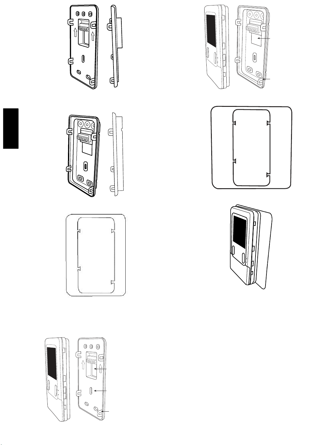
There are two options for mounting the Evolution Zone Control to
the wall. First, become familiar with all plastic assembly pieces
shown in Fig. 3 through 10. The User Interface will snap together
with either the Recess Mount or the Surface Mount backplate.
Mount
Recess
This provides the thinnest mounting configuration (See Fig. 4).
The backplate containing the recessed terminal block can be
mounted directly to the wall by cutting a hole 1 1/2” (38.1 mm)
wide by 2 1/8” (54 mm) high. Mark location and cut hole in wall.
NOTE: Always ensure the Evolution Zone Control location is
acceptable before cutting any holes in wall.
Surface
This provides surface mounting configuration, which allows use of
a small hole in the wall. A surface mount backplate is supplied (See
Fig. 5). Attach backplate as shown in Fig. 8, and the assembly will
mount directly to the wall requiring only a small hole in the wall
allowing a four wire connection to pass through.
NOTE: Once Evolution Zone Control is secured to wall with the
backplate assembly (snapped together), care must be taken not to
bend or break the interlocking tabs when removing. Gently remove
Evolution Zone Control by rocking up/down until interlocking
tabs release.
Decorative
Supplied is a thin decorative backplate (see Fig. 6) to hide any
marks/screw holes left from the previous thermostat. This
decorative backplate (or beauty ring) can be used in either the
recess or surface mount installation by snapping it onto back of
recessed mount backplate or surface mount backplate before
securing to wall. See Fig. 9 and 10 for a larger decorative backplate
P/N SYSTXXOLBP01 (5.75” / 146 mm wide x 6” / 152 mm
high), which can be ordered separately.
Mount
Backplate
Fig. 3 -- Evolution
A03185
t Zone Control
BBUIZ01--B
3
Page 4
Surface Mount
Backplate to wall
Interlocking Tabs (4)
Fig. 4 -- Recessed Mount Backplate
A03186
Fig. 8 -- Surface Mount Assembly
A03191
BBUIZ01--B
A03188
A03187
Fig. 5 -- Surface Mount Backplate
Fig. 9 -- Large Decorative Backplate
Fig. 6 -- Thin Decorative Backplate
Recessed terminal
1
block in wall 1
wide by 2
Recessed Mount
Interlocking Tabs (4)
/
" (38.1 mm)
2
1
/8" (54 mm) high
Fig. 7 -- Recessed Mount Assembly
A04017
A07150
A03192
Fig. 10 -- Decorative Backplate Assembly
4
Page 5
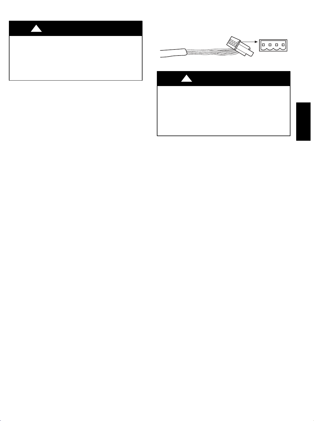
INSTALLING EVOLUTION ZONE
CONTROL
!
WARNING
ELECTRICAL SHOCK HAZARD
Failure to follow this warning could result in personal injury
or death.
Before installing Evolution Zone Control, turn off all power
to equipment. There may be more than one power source to
disconnect.
1. Turn off all power to equipment.
2. If an existing User Interface or control is being replaced:
a. Remove existing control from wall.
b. Disconnect wires from existing control.
c. Discard or recycle old control.
NOTE: Mercury is a hazardous waste, if existing control contains
any mercury, it MUST be disposed of properly. The User Interface
does not contain mercury.
3. Select Evolution Zone Control mounting plastic (recess
mount or surface mount and decorative backplate if desired).
4. Route wires through large hole in mounting plastic. Level
rear plastic against wall (for aesthetic value only -- Evolution Zone Control need not be level to operate properly) and
mark wall through two mounting holes.
5. Drill two 3/16” (4.8 mm) mounting holes in wall where
marked.
6. Secure mounting plastic to wall using two screws and anchors provided.
7. Adjust length and routing of each wire to reach each wire
entry on the connector backplate. Strip 1/4” (6.4 mm) of insulation from each wire.
8. Match and connect thermostat wires to proper terminals on
User Interface backplate. See wiring diagram Fig. 12, 13,
and 14.
A — Green = Data A
B — Yellow = Data B
C — White = 24VAC (Com)
D — Red = 24VAC (Hot)
NOTE: It is not mandatory that the above color code be used, but
each ABCD connection in the system MUST be wired consistently.
A separate ABCD Connector comes inside packaging and should
be used when connecting to furnace (or fan coil). Ensure connector
is inserted properly into circuit board. (See Fig. 11.)
ABCD
A03193
Fig. 11 -- Wire ABCD Connector
!
CAUTION
ELECTRICAL OPERATION HAZARD
Failure to follow this caution may result in equipment damage
or improper operation.
Improper wiring of the ABCD connector will cause the
Evolution Zone System to operate improperly. Check to make
sure all wiring is correct before proceeding with installation or
turning on power.
9. Push any excess wire into the wall. Seal hole in wall to prevent any air leaks. Leaks can affect operation.
10. Attach Evolution Zone Control to the mounting plastic by
lining up the plastic guides on the back of the control with
the opening on the mounting plastic and push on.
11. Perform installation of all other system equipment (i.e.
dampers, humidifier, ventilator, UV lights, etc.)
12. Turn on power to equipment.
See wiring diagrams Fig. 12, 13, and 14 for connecting the
Evolution Zone Control and Smart Sensors to the Damper Control
Module. More information regarding Damper Control set--up and
wiring can be found in Damper Control Module Installation
Instructions.
See wiring diagram, Fig. 12, which includes an indoor
communicating furnace or FE fan coil, with a 2--stage Puronr
refrigerant communicating outdoor unit. No additional OAT
(outdoor air temperature) sensor is required because the Evolution
Zone Control will use the temperature sensor inside the outdoor
unit.
See wiring diagram, Fig. 13, for connecting an indoor
communicating furnace or FE fan coil with a 1--stage air
conditioning unit (non--communicating outdoor). An Outdoor Air
Temperature (OAT) sensor may be installed (but is not required) at
the indoor furnace or fan coil OAT terminals. When OAT sensor is
applied, the Evolution System will provide enhanced system
features and benefits.
See wiring diagram Fig. 14 for connecting an FE fan coil with a
1--stage heat pump (non--communicating outdoor unit). When
OAT is applied, the Evolution System will provide enhanced
system features and benefits.
NOTE: For other applications not listed, refer to the Network
Interface Module (NIM) Installation Instructions.
BBUIZ01--B
5
Page 6
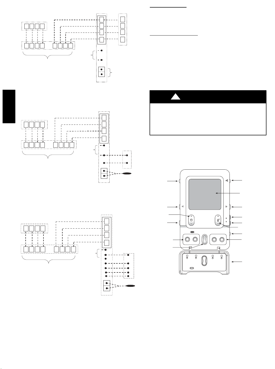
Zone Control
User Interface &
Smart Sensor(s)
A B C D
Indoor
Green
Yellow
White
Red
Unit
A
B
C
D
Communicating
A B C D A B C D
HUM
COM
24V
OAT
(Optional)
Damper
Control
module
Humidifier
Connection
Fig. 12 -- Communicating Indoor Unit w/2--Stage Puron
Refrigerant Communicating Outdoor Unit
Indoor
Zone Control
User Interface &
Smart Sensor(s)
BBUIZ01--B
A B C D
A B C D A B C D
Damper
Control
module
Green
Yellow
White
Red
Humidifier
Connection
Unit
HUM
COM
24V
Y/Y2
OAT
A
B
C
D
Fig. 13 -- Connection Diagram for Furnace or FE Fan Coil
with Non--Communicating 1--Stage AC
Green
Yellow
White
Red
Humidifier
Connection
Variable-Speed
Fan Coil
A
B
C
D
HUM
C
G
R
O
W
Y
OAT
Zone Control
User Interface &
Smart Sensor(s)
A B C D
A B C D A B C D
Damper
Control
module
Fig. 14 -- Connection Diagram for FE Fan Coil with
Non-- Communicating 1--stage HP
Humidifier Connection
A 24VAC bypass or fan powered humidifier may be installed.
NOTE: Do Not Use a traditional humidistat to control humidifier
operation. If a humidifier is installed, let the Evolution Zone
Control operate humidifier.
AC or HP
A
B
C
D
OAT
Sensor
1-Stage AC.
1-Spd. HP
A04018
C
Y
OAT
Sensor
A04019
Sensor
A07149
r
OAT
Humidifiers
Bypass
A bypass humidifier should be wired directly to the furnace or fan
coil HUM and 24VAC COM terminals. The Evolution Zone
Control will automatically energize the HUM output during a call
for humidification.
Fan Powered
Humidifiers
Most fan powered humidifiers produce internal 24VAC in order to
energize upon a switch or contact closure. For this application, a
24VAC N.O. Isolation Relay (DPST) MUST be used to prevent
mixing the internal humidifier power with the indoor equipment
transformer. Applying 24VAC isolation relay coil to furnace or fan
coil HUM and COM terminals will allow the Evolution Zone
Control to automatically energize the HUM output during a call for
humidification. The N.O. relay contacts will be used to energize the
humidifier. See fan powered humidifier installation instructions for
more details.
!
CAUTION
EQUIPMENT HAZARD
Failure to follow this caution may result in equipment damage.
Do not apply 24VAC fan powered humidifier (with internal
power supply) direct to indoor unit HUM and COM terminals.
INITIAL POWER--UP
NOTE: Refer to Functional Overview (Fig. 15) to become
familiar with key function buttons such as “System On/Off”,
“Zone”, “Fan”, “Left--Side” and “Right--Side” buttons, etc. These
function buttons will be used frequently during setup.
Zone
Button
Left-Side
Button
Time (+/-)
Button
Hold
Button
Schedule & Vacation
Program Buttons
Up/Down
C
R
O
W2
Y
Scroll Buttons
ZONE
HOLD
SCHEDULE VACATION
PROGRAM
Schedule
to program
temperature
schedule
Vacation
to start/end
vacation
SCROLL
Scroll
up & down
BASIC
Basic
to set time,
humidity
SETUPS
ADVANCED
Advanced
for all other
settings
HEAT
COOL
Fig. 15 -- Functional Overview
Power Up Sequence
This section addresses initial power up (or commissioning) of a
new Evolution Zone Control. The User Interface will communicate
and identify all Evolution components in the system. The
following is a typical example for a communicating
Variable--Speed Furnace / Fan Coil with a 2-- stage Air Conditioner
/ Heat Pump (including Hybrid Heat).
The User Interface display will light up and indicate that it is now
“ESTABLISHING COMMUNICATIONS WITH EQUIPMENT
PLEASE WAIT”. The User Interface will automatically continue
by “SEARCHING FOR EQUIPMENT”, followed by
“SEARCHING FOR OUTDOOR EQUIPMENT” (See Fig. 16).
Fan Button
Display Screen
(LCD)
Right-Side
Button
Heat Button
Cool Button
Temperature
(+/-) Button
System
On/Off Button
Basic & Advanced
Setup Buttons
Flip Down
Door
A04038
6
Page 7
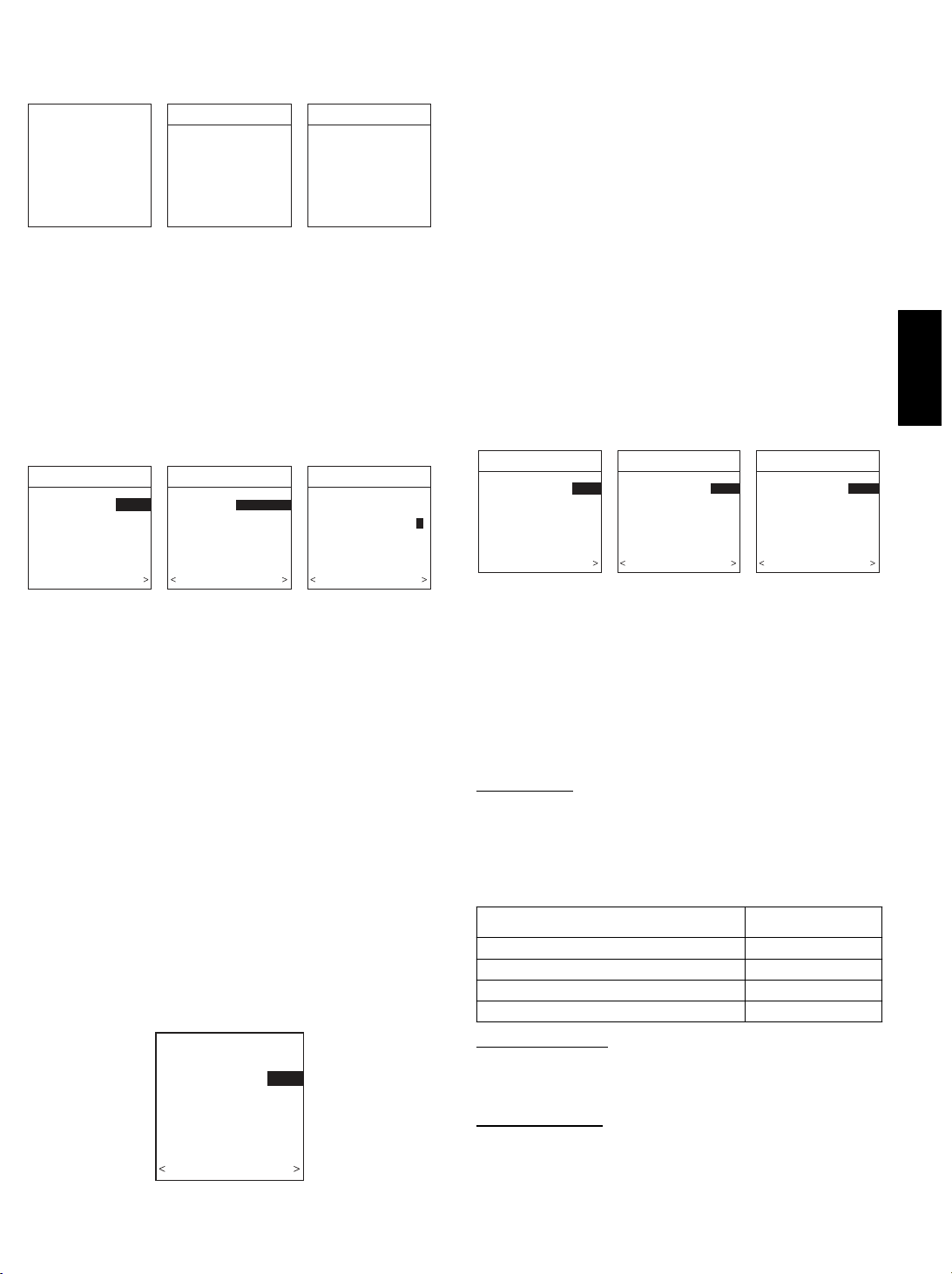
Once the indoor and outdoor equipment has been found, the
Installer will be asked to select Accessories. Packaged Products
will be automatically identified and the Installer will be asked to
select Accessories. Proceed to Selecting Accessories.
ESTABLISHING
COMMUNICATIONS
WITH EQUIPMENT
PLEASE WAIT
SOFTWARE
VERSION
INDOOR UNIT
SEARCHING FOR
INDOOR EQUIPMENT
WORKING
OUTDOOR UNIT
SEARCHING FOR
OUTDOOR EQUIPMENT
WORKING
A03195
Fig. 16 -- Power Up Sequence
NOTE: If the variable--speed indoor equipment (furnace or fan
coil) cannot be found, the User Interface will display “CANNOT
COMMUNICATE WITH INDOOR UNIT”. This MUST be
corrected before the initial power up sequence can continue. If
indoor unit is found, but outdoor unit is not found, “OUTDOOR
UNIT NOT IDENTIFIED” will appear. Proceed to the next section
for Outdoor Unit Identification.
Selecting Outdoor Unit
OUTDOOR UNIT
NOT IDENTIFIED
SELECT TYPE:
NONE, AC, HP
PRESS +/- TO MAKE
SELECTION
CONTINUE
NONE
OUTDOOR UNIT
ENTER HEAT PUMP
SIZE
18000 TO 60000 BTU
PRESS +/- TO MAKE
BACK CONTINUE
36000 BTU
SELECTION
OUTDOOR UNIT
HEAT PUMP
ENTER NUMBER OF
SPEEDS, 1 or 2:
PRESS +/- TO MAKE
SELECTION
BACK CONTINUE
1
If the equipment is a fan coil, packaged heat pump, or packaged
AC and the electric heater is not self--identifying, “ELECTRIC
HEATER NOT IDENTIFIED” will appear (See Fig. 18). Press
either Time or Temp +/-- buttons to select appropriate size of
electric heater installed, then press right--side button to continue.
An asterisks (*) will appear next to electric heater sizes that may
cause excessive airflow.
NOTE: Range of electric heaters available is limited by model
number of the equipment installed. The Evolution Zone Control
will not allow an electric heater size that is not supported by the
installed equipment.
Hydronic Heat Applications
The --B model of the Evolution Zone Control supports Hydronic
Heat applications in the form of a hot water coil on FE fan coils
only. If an FE fan coil is installed, a Hydronic Heat kit should be
installed in place of the electric heater. See FE fan coil Product
Data for accessory part number. The system will identify that
hydonic heat has been installed during the initial commissioning
process. The system will treat the hot water coil as either auxiliary
heat in a heat pump application, or the sole heat source. Setup
options for Hydronic Heat applications are described in the Setup
section of this instruction.
Selecting Accessories
ACCESSORIES
AIR FILTER TYPE:
EAC
MEDIA
MEDIA + EAC
PRESS +/- TO MAKE
SELECTION
CONTINUE
AIR FILTER MEDIA TYPE HUMIDIFIER INSTALLED? U.V. LIGHTS INSTALLED?
EAC
ACCESSORIES
HUMIDIFIER
INSTALLED?
PRESS +/- TO MAKE
SELECTION
BACK CONTINUE
YES
ACCESSORIES
U.V. LIGHTS
INSTALLED?
PRESS +/- TO MAKE
SELECTION
BACK CONTINUE
YES
BBUIZ01--B
A03196
Fig. 17 -- Selecting Outdoor Unit
If there is no communicating outdoor unit, the screen, shown in
Fig. 17, will appear. Press either Time or Temp +/-- buttons to
select AC (air conditioner), HP (heat pump), or None (no unit
installed). Press right--side button to continue to next screen.
If either AC or HP has been selected as the outdoor unit type, the
middle screen will appear (See Fig. 17). Press either Time or Temp
+/-- buttons to select appropriate Btu size of outdoor unit, then
press right side button to continue. If a NIM (Network Interface
Module) is applied for non--communicating two--stage outdoor
equipment, select 1 or 2--stage compressor operation, and press
right--side button to continue.
NOTE: Range of outdoor unit Btu selection is limited by model
number of indoor unit installed. The Evolution Zone Control will
not allow an outdoor unit size that is not supported by the installed
indoor unit.
NOTE: On new system installations, the model and serial number
will be recognized and displayed. On any indoor/outdoor board
replacements, the equipment will be recognized but the exact
model/serial number will not be displayed.
Selecting Electric Heater
ELECTRIC HEATER
NOT IDENTIFIED
ENTER SIZE:
NONE, 5,10,15 KW
PRESS +/- TO MAKE
SELECTION
BACK CONTINUE
Fig. 18 -- Selecting Electric Heater
5 KW
A03197
A03198
Fig. 19 -- Accessories —UV Lights
Once the indoor and outdoor equipment have been found or
entered, the following screens will appear allowing the Installer to
select the “AIR FILTER TYPE; HUMIDIFIER INSTALLED”;
and “UV LIGHTS INSTALLED” (See Fig. 19). Use either Time or
Temp +/-- buttons to make appropriate selections in the highlighted
area on the display screen. Press right--side button to continue (or
advance) to the next screen.
Air Filter T
ype
This accessory screen will appear first. The installer will need to
enter the type of filter (MEDIA, EAC, or both). See Table 1 and
make a selection using Time or Temp +/-- button, then press
right--side button to continue.
Table 1 – Filter Selection
INSTALLED FILTER
1inchto4inchmedia MEDIA
High voltage EAC EAC
High voltage EAC + 1 to 4 inch media MEDIA + EAC
Evolutiont Air Purifier MEDIA
MENU
SELECTION
Humidifier Installed
This will appear after the Air Filter Type screen. Select whether a
humidifier is installed on the system, YES or NO, then press
right--side button to continue.
UV Lights
Installed
This screen will appear to select whether UV lights are installed on
the system, select YES or NO, then press right--side button to
continue.
7
Page 8
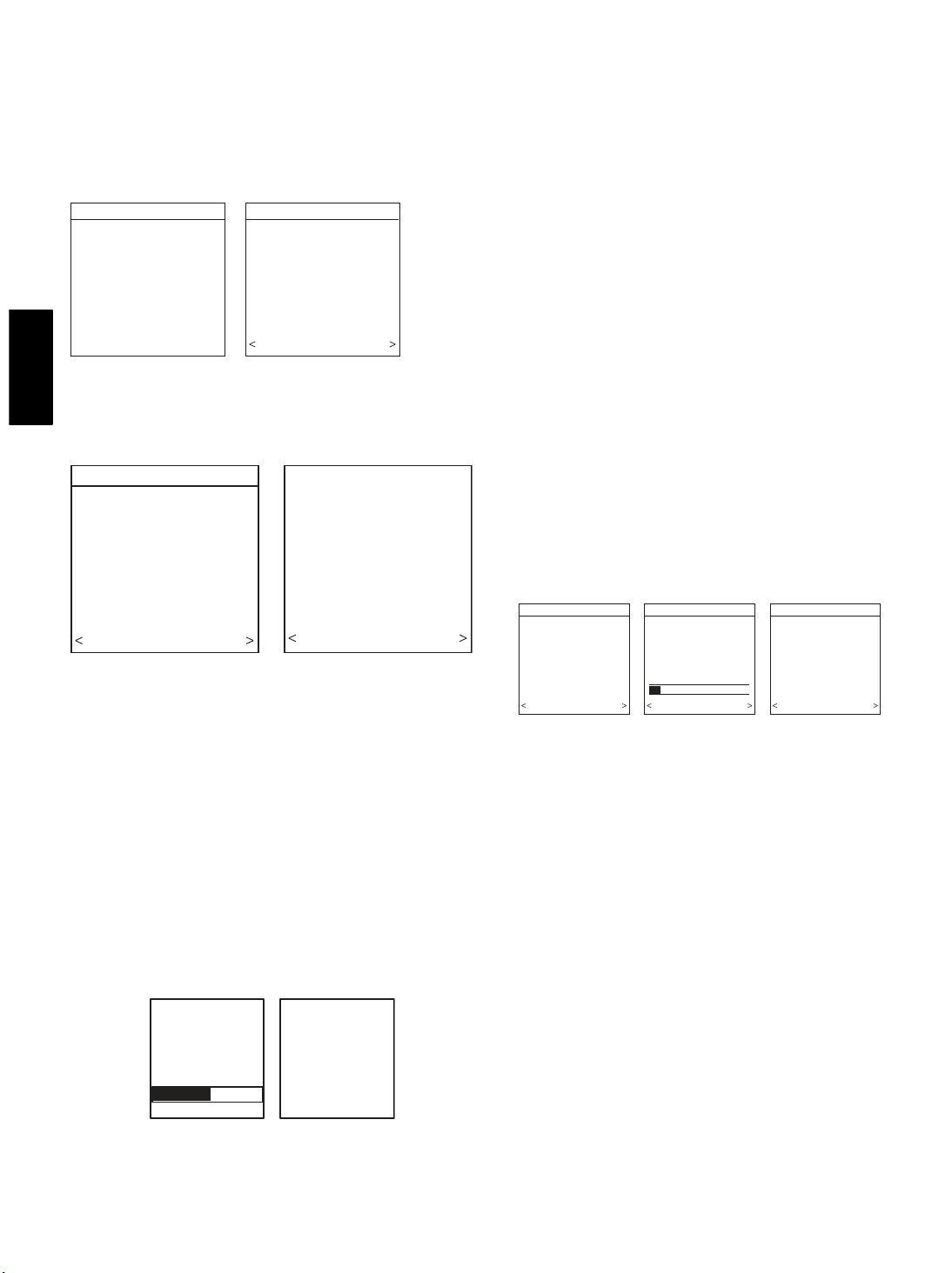
Zoning
“SEARCHING FOR ZONE EQUIPMENT” will appear on the
screen to identify the number of zones detected. This screen will
show Zone 1, Zone 2, etc. and indicate all zones having either a
Remote Room Sensor, or smart sensors associated with them. If the
system contains smart sensors, they must be assigned a zone
number before continuing. See Smart Sensor Installation
Instructions on how to assign Smart Sensors to their respective
zones. When finished, press right--side button to continue. See Fig.
20.
ZONING
SEARCHING FOR
ZONE EQUIPMENT
WORKING
BBUIZ01--B
ZONE 1 UI
ZONE 2 RS
ZONE 3 RS
ZONE 4 RS
UI=USER INTERFACE
RS=REMOTE SENSOR
SS=SMART SENSOR
BACK CONTINUE
Fig. 20 -- Zoning
ZONING
Equipment Summary
EQUIPMENT SUMMARY
FURNACE
AC 180ANA024
FILTER EAC
HUMIDIFIER YES
UV LIGHTS YES
ZONES 12345678
355MAV042
SETUP
COMPLETE!
SAVE
ALL SELECTIONS/
NO YES
NO YES
Fig. 21 -- Equipment Summary
The “EQUIPMENT SUMMARY” screen will appear after
Accessories have been selected. This screen will give a summary of
all equipment automatically found or manually selected. If a wrong
selection was made, press left--side button (BACK selection) to go
back to that particular screen and make changes. When everything
is OK, press right--side button again to continue. (See Fig. 21.)
The “SETUP COMPLETE! SAVE ALL SELECTIONS?” screen
will appear after Equipment Summary. To Save All Selections
press (YES) right--side button. Pressing the left--side button (NO
selection) will return to the Equipment Summary screen where
changes can be performed to any of the equipment selection
screens. After selecting YES, the initial power up sequence of the
new Evolution Zone Control is complete.
Static Pressure Check
STATIC
PRESSURE
CHECK
PLEASE WAIT
Fig. 22 -- Static Pressure Check
This screen will appear after Setup is exited. The system will open
all dampers and perform a static pressure check. This process will
EXTERNAL STATIC
PRESSURE
MEASURED:
0.72 INCHES
AT 1200 CFM
CONTINUE >
A04084
A07251
A05000
take about 1 1/2 minutes to complete. When completed, a screen
will appear displaying the static pressure (in inches) across the
equipment at the expected highest delivered airflow. If the static
pressure is over 1 inch, a warning will appear, but equipment
operation and the TrueSenset dirty filter detection operation will
not be affected.
NOTE: The static pressure check occurs only at initial installation,
or when INSTALL is run in the INSTALL/SERVICE menu.
Duct Assessment
The following screen will appear after STATIC PRESSURE screen
is exited. Press right--side button to start Duct Assessment. Duct
Assessment will measure the relative size of the ductwork, up to
and through the dampers. These measurements are used to control
the correct amount of airflow in the zoned system. Status messages
will appear on the screen to indicate what the system is doing. The
process will take approximately one minute per zone. The duct
assessment will override a call for heat or cool.
A duct assessment will automatically occur each day at a user
selectable time. The factory default time is 1:00 p.m. but, may be
changed by entering the Zoning Setup menu. See Zoning Setup
section of this manual. The duct assessment will override a call for
heat or cool. The system will first open all zones and drive the
blower to 175 CFM/ton of cooling (or the minimum indoor unit’s
airflow, whichever is greater). It will then take a static pressure
measurement. The system will then close all zones and open one
zone at a time, taking a static pressure measurement for each zone.
The system will then close all zones and take a pressure
measurement, getting a value for the duct leakage up to and
through the dampers. With these static pressure measurements, the
system will calculate the relative size of each zone as well as the
percent leakage through the dampers At the end of the process, the
display will show the relative size of each zone duct. See Fig. 23.
DUCT ASSESSMENT
MEASURE DUCT
CAPACITY FOR EACH
ZONE.
4 MINUTES ARE REQUIRED
TO COMPLETE
PRESS START TO BEGIN
QUIT START
DUCT ASSESSMENT
ASSESSMENT ACTIVE
PLEASE WAIT
OPENING ALL ZONES
AIRFLOW STABILIZING
PROGRESS
STOP
DUCT ASSESSMENT
ZONE CAPACITY
ZONE1 25
ZONE 2 20
ZONE 3 25
ZONE 4 20
DAMPER LEAKAGE 10
QUIT START
A04085
Fig. 23 -- Duct Assessment
QUICK START
For first time installers, Quick Start will allow a quick start up of
the Evolution Zone System before learning all the details of system
operation. However, for the best possible comfort and operation
refer to the Evolution Zone Control Owner’s Manual.
Set Day, Time & Desired Humidity
1. Flip down the door at the base of the Evolution Zone Control and press the BASIC button.
2. Adjust the highlighted HOUR setting using the TIME
(+/--) button.
3. Press SCROLL button (down) to highlight MINUTE.
4. Adjust the MINUTE setting using the TIME (+/--) button.
5. Press SCROLL button (down) to highlight DAY.
6. Adjust the current DAY setting using the TIME (+/--) button.
7. Press SCROLL button (down) to highlight HUMIDITY.
8. Press the red HEAT button to select heating humidity.
9. Adjust desired heating humidity level using either (+/--) button.
10. Press the blue COOL button to select cooling humidity.
11. Adjust the desired cooling humidity level using either(+/--)button.
8
Page 9
12. To exit press BASIC button or close door.
13. If changes are made, you will be asked to “SAVE
CHANGES? YES/NO.”
Override Heating Schedule
1. Press the red HEAT button. Heating mode is confirmed
when the red LED next to the red HEAT button is lit.
2. Use the TEMP (+/--) button to select your desired heating
temperature.
3. The default time for temporarily overriding the temperature
schedule is 2:00 HRS as indicated by the text on the lower
left.
NOTE: Override time will not appear if programming has been
turned off.
4. You can change the temporary override time in 15--minute
increments by pressing the TIME (+/--) button until the desired override time is selected, or press the HOLD button
anytime to override the schedule indefinitely.
Quick Program Schedule For All Days
This section will give you a quick program schedule for ALL
DAYS of the week. For more information on how to create
customized schedules for every day, the entire week, or weekend,
refer to the Owner’s Manual.
1. Flip down the door at the bottom of the control.
2. Press the SCHEDULE button, which allows you to create
one schedule for the entire home.
3. Press either the LEFT or RIGHT side button repeatedly (if
necessary) until “ALLDAYS” is displayed. The WA KE
time period will be highlighted.
4. Using the TIME (+/.) button, set the start time for this time
period.
5. Press the red HEAT button. Heating temperature will begin
flashing.
6. Set the heating temperature using the TEMP (+/.) button.
7. Press the blue COOL button. Cooling temperature will begin flashing.
8. Set the cooling temperature using the TEMP (+/.) button.
9. Set the remaining periods by using the SCROLL button to
select “DAY”, “EVENING”, and “SLEEP”.
10. To copy a zone, use SCROLL button to select “COPY”.
Select YES and copy this zone schedule to other zones using NO or YES.
11. Exit the scheduling mode by either closing the door or
pressing the SCHEDULE button.
12. If changes are made, you will be asked to “SAVE
CHANGES YES/NO.”
INSTALL / SERVICE MENUS
The “INSTALL / SERVICE” menus contain a set of vital
information. This information enables the Installer or Service
person to view a summary of what has been installed, etc. This
information is not covered in the Owner’s Manual.
To ent er INSTALL / SERVICE menus, press and hold the
ADVANCED button for at least ten seconds. The following menu
will appear (See Fig. 24):
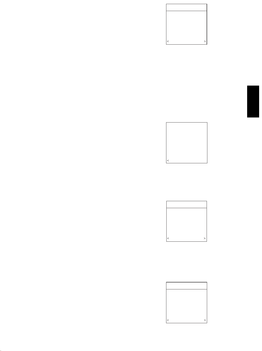
INSTALL/SERVICE
EQUIPMENT SUMMARY
INSTALL
SETUP
CHECKOUT
SERVICE
SOFTWARE VERSION 1
EXIT SELECT
A03200
Fig. 24 -- Install / Service Menus
NOTE: The INSTALL / SERVICE menu will automatically exit
after 60 minutes of no push button activity.
EQUIPMENT SUMMARY: Shows all equipment recognized by
and attached to the system.
INSTALL: Used when adding, changing out, or un-- installing
equipment.
SETUP: Used to view or modify equipment settings.
CHECKOUT: Allows testing of equipment operation
SERVICE: Used to view operation and fault history of equipment
and enter dealer name/phone number for display
EQUIPMENT SUMMARY MENU
EQUIPMENT SUMMARY
FURNACE
AC
FILTER EAC
HUMIDIFIER YES
UV LIGHTS YES
ZONES 1234
BACK
355MAV042
180ANA024
A07252
Fig. 25 -- Equipment Summary
This screen shows indoor unit type and model number, outdoor
unit type (and model number if a 2--stage unit), filter type and any
accessories that are installed, and how many zones are recognized.
INSTALL MENU
INSTALL
TO ADD, UNINSTALL OR
RE-INSTALL EQUIPMENT,
PRESS RIGHT SIDE
BUTTON
BACK INSTALL
A03202
Fig. 26 -- Install Menu
This menu item will perform start-- up process in order to learn all
equipment in system. Press right side button to initiate the process.
See Fig. 26.
SETUP MENU
SETUP
THERMOSTAT
FURNACE
HEAT PUMP
ZONING
ACCESSORIES
SYSTEM MAINTENANCE
BBUIZ01--B
BACK SELECT
A04089
Fig. 27 -- Setup Menu
9
Page 10
This menu has several layers, allowing modification of equipment
settings. No settings will need to be made at equipment (i.e. DIP
switches on a furnace). All configuration settings made effective
from this menu will override equipment configuration made by dip
switches. Fig. 27 shows all the information that can be found in the
SETUP menu.
Setup -- Thermostat
Auto Mode
When Auto mode is enabled (factory default) a change from heat
to cool (or vice versa) will not occur until an opposite mode
demand has existed for 30 minutes. If the setpoint is changed, the
30 minute timer is deleted.
Heat/Cool
The minimum difference enforced between heating and cooling
desired temperatures. This can allow one setting to “push” the
other to maintain this difference.
BBUIZ01--B
Offsets:
This option allows calibration (or deliberate miscalibration) of the
temperature and humidity sensors. These offsets are added to the
actual temperature/humidity values (defaults=0).
Cycles Per
ogramming:
Pr
Smart
Applies to programmable operation only. Will start recovery 90
minutes prior to schedule change in both heating and cooling
mode. Refer to operational information for more detail.
English/Metric
Reset Factory
Program Schedule:
User Settings:
Install Settings:
Setup:
S Enable/Disable Auto Changeover mode (default=En-
able).
S Auto Changeover Time may be adjusted 5 to 120 min-
utes, (default = 30 minutes).
Deadband:
S 0to6_F/0to3.3_C, (default = 2_F/1.1_F).
S Zone1Offset:--5to+5_F(--2.8_Cto+2.8_C).
S Outside Temp Offset: --5 to +5_F(--2.8_Cto+2.8_C).
S Humidity Offset: --10 to +10%.
Hour:
S Maximum cycles per hour = 4 (default) or 6.
S Anticipator = 1 to 9 (default=3). This adjusts sensitivity
to temperature changes. 1 = most sensitive, 9 = least sensitive.
S If space is over--conditioning, increase the anticipator
setting.
S If space is under--conditioning, decrease the anticipator
setting.
S ON (default)-- allows program schedule to be set by user.
S OFF -- system becomes non--programmable
S Periods Per Day = 2 or 4 (default=4)
S Programmable Fan On/Off (default=Off). If ON is se-
lected, fan can be set to Auto, Low, Med, or High.
Recovery:
S On or Off (default=On)
Display:
S_For_C (default = _F)
Defaults:
S Yes/No to reset back to Energy Star default Time and
Temp schedules.
S Yes/No to reset the user settings in the Advanced Setup
to factory default settings.
S Yes/No to reset install settings in Install/Service menus to
factory default settings.
Last 10 System Events:
S Yes/No to reset last 10 system events under Service Info
menu.
Setup -- Furnace
Upon a first time start--up of the Evolution Zone Control, the
furnace DIP switch settings will be copied to the furnace setup
menu. Any changes can then be made from the Evolution Zone
Control.
Airflow:
S COMFORT (default)
S EFFICIENCY
Selects the airflow of the furnace when heating. EFFICIENCY is
the airflow used to meet specified ratings, COMFORT is a
decreased airflow used to increase the output air temperature and
provide increased comfort.
AC
Airflow:
S COMFORT (default) -- cooling airflow is varied depend-
ing on humidity and temperature demands settings. This
selection enables the full dehumidify and comfort capabilities of the system. When COMFORT is not selected,
the unit will not run reduced aiflows for dehumidification.
S EFFICIENCY -- fixed airflow used to achieve specified
ratings -- no dehumidification airflow reduction. This is
nominally 350 CFM/ton, but will vary if a 2--stage outdoor unit is used.
S MAXIMUM -- 400 CFM/ton.
Dehum
Low Heat
Set to ON if the system contains a bypass humidifier. The ON
setting will increase the furnace low heat airflow.
Staging
Controls the staging of the furnace. SYSTEM setting will allow
the Evolution Zone Control to determine furnace staging. LOW
will only run the low stage of furnace heat. HIGH will only run
the high stage of furnace heat.
GT
This setup option selects desired operation when the R-- G circuit
changes state on the furnace control board depending on setup.
Airflow:
S NORMAL (factory default) -- When equipment is run-
ning to dehumidify, the airflow is allowed to adjust to a
minimum to satisfy the dehumidification call.
S HIGH -- Minimum airflow during the dehumidify mode
is increased to reduce duct and register sweating. Also
increases minimum airflow during normal cooling operation to reduce duct sweating.
Rise
S ON
S OFF (default)
S SYSTEM (default)
S LOW
S HIGH
erminal
S DISABLED (Default)
S FAN -- turns on fan to selected fan speed when G termi-
nal is energized. See Fig. 28.
S FAN SPEED -- select Low, Med, High for all zones
when G terminal is energized
S SHUTDOWN -- shuts off fan and equipment when initi-
ated. This function may be activated by a dry contact
from an external device such as a float switch or a relay.
User selects whether the contact is NC -- normally closed
(default) or NO -- normally open. User Interface displays
SYSTEM MALFUNCTION on screen and registers G
10
Page 11
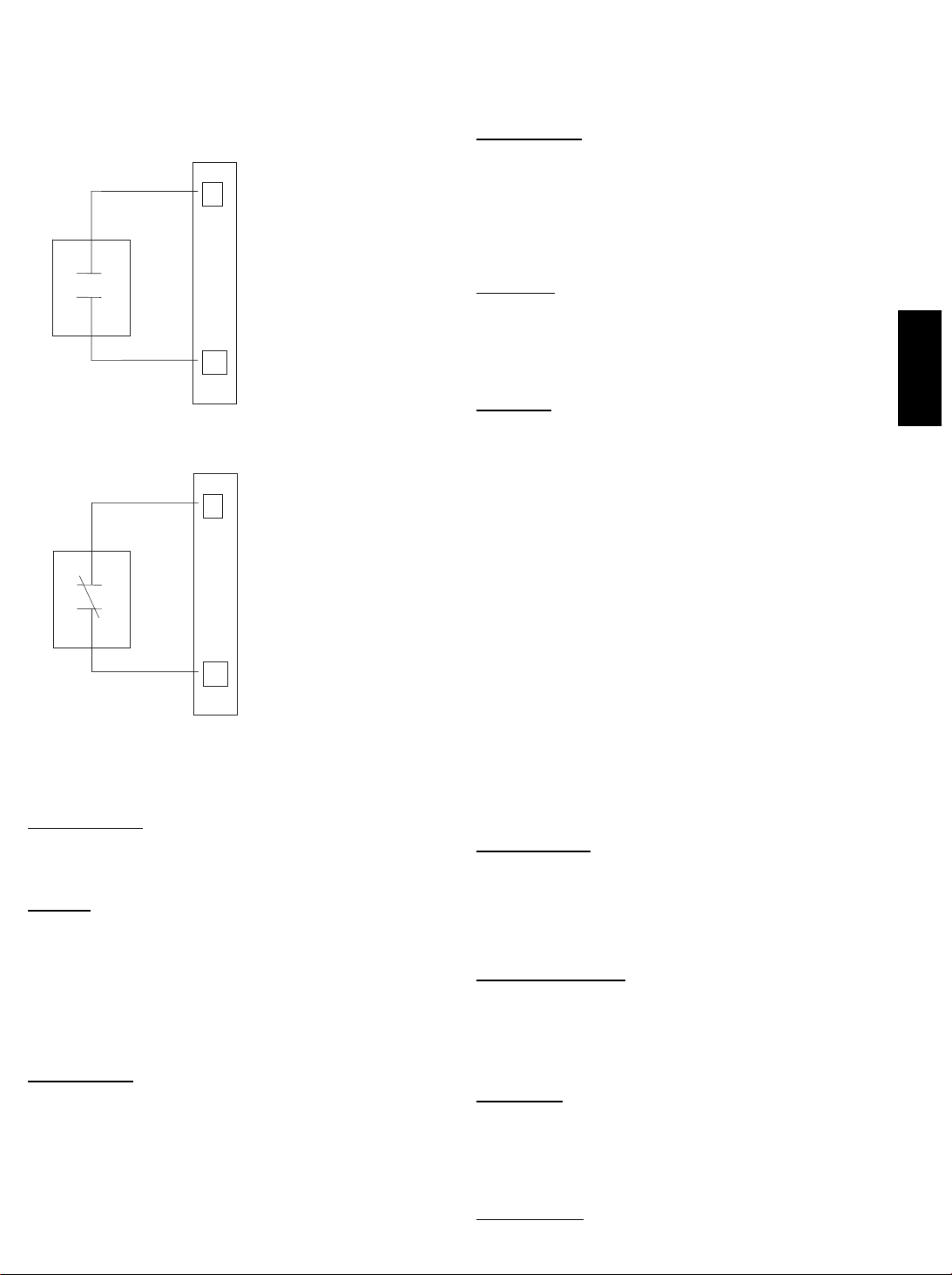
terminal shutdown event in Last 10 System Events. See
Fig. 29.
S GEN (generator input) -- displays GENERATOR MAL-
FUNCTION pop--up message when G is energized. This
function requires the addition of a Generator Self Test
Verifier (Part No. GSV200) which must be purchased
separately. Visit www.GeneratorVerifier.com for details
and ordering information. See Fig. 28.
R
FE Fan Coil or
Variable Speed Furnace
G
A07114
Fig. 28 -- G Input Wiring for Blower Operation or Generator
Malfunction with (--B) Evolution
R
FE Fan Coil or
Variable Speed Furnace
G
t Control
A07115
Fig. 29 -- G Input Wiring for System Shutdown
with (--B) Evolution
t Control (Contact type selectable;
Normally Closed (default) or Normally Open)
High Stage Timer
Minimum amount of time low stage must operate before high stage
is activated. Ten to 60 minutes. 10 = default
A demand of 5_F/2.8_C or more will override the staging timer.
Delay
Off
S 90 seconds
S 120 seconds (default)
S 150 seconds
S 180 seconds
Amount of time the blower will continue to run after heating has
shut off.
Setup -- Fan Coil
HP/AC
Airflow:
S COMFORT (default) Cooling airflow is varied depend-
ing on humidity and temperature demand settings. This
selection enables the full dehumidify and comfort capabilities of the system. When COMFORT is not selected,
the unit will not run reduced airflows for dehumidification. Heat Pump airflow is varied depending on outdoor
temperature to maximize comfort.
S EFFICIENCY -- fixed airflow used to achieve specified
ratings -- no dehumidification airflow reduction. This is
nominally 350 CFM/ton, but will vary if a 2--stage outdoor unit is used.
S MAXIMUM -- 400 CFM/ton. Dehumidify features are
not active when set to maximum.
Airflow:
Dehum
S NORMAL (factory default) -- When equipment is run-
ning to dehumidify, the airflow is allowed to adjust to a
minimum to satisfy the dehumidification call.
S HIGH -- Minimum airflow during the dehumidify mode
is increased to reduce duct and register sweating. Also
increases minimum airflow during normal cooling operation to reduce duct sweating.
Size:
Heater
S (choices dependent upon fan coil model)
This will show the heater size entered during the start--up process.
This value can be changed to another value (limited by the model
number of the fan coil). If the electric heater is self--identifying, this
value is not shown.
GT
erminal
This setup option selects desired operation when the R--G circuit is
made on the fan coil control board.
S DISABLED (Default)
S FAN -- turns on fan to selected fan speed when G termi-
nal is energized. See Fig. 28.
S FAN SPEED -- select Low, Med, High for all zones
when G terminal is energized.
S SHUTDOWN -- shuts off fan and equipment when initi-
ated. This function may be activated by a dry contact
from an external device such as a float switch or a relay.
User selects whether the contact is NC -- normally closed
(default) or NO-- normally open. User Interface displays
SYSTEM MALFUNCTION on screen and registers G
terminal shutdown event in Last 10 System Events. See
Fig. 29.
S GEN (generator input) -- displays GENERATOR MAL-
FUNCTION pop--up message when G is energized. This
function requires the addition of a Generator Self Test
Verifier (part No. GSV200) which must be purchased
separately. Visit www.GeneratorVerifier.com for details
and ordering information. See Fig. 28.
Setup -- Heat Pump / AC
Cooling
Outside temperature below which cooling will not be provided.
Low Ambient
Selecting YES will enable the low ambient cooling operation in
the outdoor unit. This setting is only available with communicating
outdoor units and with Cooling Lockout set to NONE.
Entered
Size of the outdoor unit entered during the start--up process. If the
outdoor unit is a communicating model, this value will not be
shown. This size can be changed here but is limited to sizes that the
indoor unit can handle.
Defrost
Lockout:
S NONE (default)
S 45_F/7_C
S 50_F/10_C
S 55_F/13_C
Cooling:
S NO (default)
S YES
Size:
S (dependent on indoor unit model)
Interval:
S 30 minutes
BBUIZ01--B
11
Page 12
S 60 minutes
S 90 minutes
S 120 minutes (default)
S Auto--Defrost interval optimized by outdoor control (de-
fault for communicating HP)
Time interval at which defrost cycles can occur on a heat pump.
Elect Heat
Lockout
S NONE (default)
S +5 to 55_F / --15 to 18_C
Outside temperature above which the electric heat will not operate
except for defrost.
High Cool Latch:
S NONE (default)
S 80 to 110_F / 27 to 43_C
Outside temperature above which only the high speed (of a 2--stage
outdoor unit) will run when cooling.
High Heat
Latch
S OFF (default)
S 20 to 50_F/--7to10_C 2 --stage heat pump runs only
BBUIZ01--B
high stage heating below a selectable outdoor temperature. Selections from 20 to 50_F/--7to10_C are avail-
able in 5_F/2.8_C increments.
Setup -- Hybrid Heat
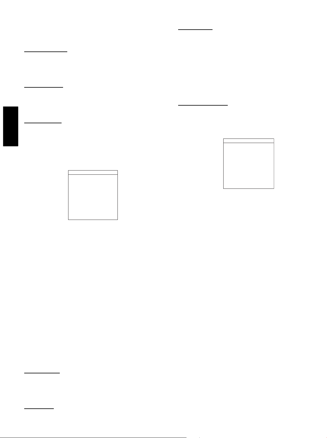
HYBRID HEAT SETUP
OUTSIDE LOCKOUT TEMPS
FURNACE
LOCKOUT:
HEAT PUMP
LOCKOUT:
DEFROST W/FURNACE: YES
HP TO FURNACE
STAGE TIME:
< BACK
> 30 F
< 15 F
15 MIN
Fig. 30 -- Hybrid Heat Setup
FURNACE LOCKOUT -- Temperature above which the furnace
will not operate, except for defrost.
S Default = NONE
S Available settings = NONE thru >55_F/13_C
HEAT PUMP LOCKOUT -- Temperature below which the heat
pump will not operate.
S Default = NONE
S Available settings = NONE thru <55_F/13_C
DEFROST W/FURNACE -- Choose whether furnace operates
during defrost cycle
S Default = YES
S Available settings = YES / NO
HP TO FURNACE STAGING TIME -- Adjust the minimum
amount of time high stage heat pump will run before furnace will
be allowed to run.
S Default = 15 MIN
S Available settings = 15--60 minutes
Setup -- Zoning
Zoning:
Disable
S NO (default)
S YES
If YES is selected, zoning is disabled and all dampers open. The
system will run un--zoned using the Zone 1 sensor.
Offsets:
Zone
S Zone Temperature Offsets (default = 0) Range --5_Fto
+5_F/--2.8_Cto+2.8_C
A07030
This option allows actual temperature offset for each zone,
allowing calibration (or deliberate miscalibration) of each sensor.
Humidifier interval is time only, not actual humidifier run time.
Airflow
Limits:
Since bypass damper is prohibited in this system, this setting is
used to select the maximum allowable noise/airflow relationship
into each zone based on air noise and comfort requirements. For
setup guidelines, see Airflow Limits Checkout in the next section.
S Low -- 100% of maximum assessed airflow
S Medium -- 150% of maximum assessed airflow
S High (default) -- 200% of maximum assessed airflow
S Maximum -- no limit
Assessed airflow is determined as described in DUCT
ASSESSMENT.
Duct Assessment T
ime
1 p.m. (default), adjustable in 1 hour increments from 1 p.m. to 12
AM (24 hours). Select which hour of the day the duct assessment
will be performed.
Setup -- Hydronic Heat
HYDRONIC HEAT SETUP
HOT WATER
LOCKOUT:
HEAT PUMP
LOCKOUT:
DEFROST W/WATER:
AIRFLOW:
BLOWER ON DELAY:
BLOWER OFF DELAY:
< BACK
Fig. 31 -- Hydronic Heat Setup
HOT WATER LOCKOUT -- Outside temperature above which the
hot water will not operate except for defrost (if selected).
S Available settings -- NO, 5 to 55_F / --15 to 13_Cin1_F
/.6_C increments
HEAT PUMP LOCKOUT -- Outside temperature below which the
heat pump will not operate, 1_F/.6_C resolution.
S Appears only with a heat pump outdoor unit.
S Available settings -- NO, 5 to 55_F / --15 to 13_Cin1_F
/.6_C increments
DEFROST W/WATER:
S Available settings: YES / NO (Default =YES)
S Appears only if heat pump is available. If no, hot water
will not run during a defrost.
AIRFLOW -- Selects desired airflow during Hydronic Heating
S Available range from OFF, 500 CFM(minimum) to 400
CFM/ton cooling maximum in 50 CFM increments.
S Default is the cooling airflow. (350 CFM/ton)
S OFF selection does not turn off airflow if heat pump is
defrosting.
BLOWER ON DELAY -- Time after hot water is requested that the
blower will turn on.
S Available settings -- 0 to 240 seconds in 30 second incre-
ments
S Default is 30
S Does not appear if a heat pump is present since heat
pump and hot water run simultaneously.
BLOWER OFF DELAY-- Time after hot water request terminates
before the blower will turn off.
S Available settings -- 0 to 240 seconds in 30 second incre-
ments
S Default is 0
> 30 F
< 45 F
YES
800 CFM
30 SEC
30 SEC
A07031
12
Page 13
Setup -- Accessories
ype:
Filter T
S MEDIA (i.e. TrueSenset)
S EAC
S MEDIA+EAC (i.e. TrueSenset)
CLEAN INTERVAL: 30 to 180 days (of actual blower operation).
(Default = 90)
Interval at which the Clean Filter notification will turn on. Applies
to EAC filter selection only.
Humidifier
Installed:
S NO
S YES
If YES, indicates to the system whether a humidifier is installed
and enables humidification functions.
CHANGE PAD INTERVAL: 1 to 24 months (default=12 months)
Interval at which the Change Humidify Pad notification will be
displayed.
HUMIDIFY WITH FAN:
S NO (default)
S YES
If YES, the humidifier will turn on if there is a humidify demand
present. The fan will turn on to Low speed if the fan setting is
Auto.
V
entilator:
NOTE: Only appears if ventilator is installed.
CLEAN INTERVAL:
S 60 to 180 days of actual operation (default=90)
Interval at which the Clean Ventilator Pre--filter notification will
turn on.
UV Lights Installed
S NO
S YES
If YES, indicates to the system whether UV lights are installed.
CHANGE INTERVAL:
S 6 to 48 months operation time (default=12 months)
Interval at which the Change UV Lights notification will be
displayed.
Setup -- System Maintenance
Remind Owner of Routine Maintenance
This setup is used to adjust the timer interval in which the normal
System Maintenance notification is turned on for the homeowner.
Range =
S OFF
S 6 to 24 months, (default=12 months) Pressing the right
side button will reset the timer. Pop--up confirmation will
be shown.
SYSTEM MAINTENANCE
REMIND OWNER OF
MAINTENANCE EVERY:
% USED: 50%
< BACK
Fig. 32 -- System Maintenance
Every:
12 MONTHS
RESET >
A07033
Setup -- Utility Saver
Cooling/Heat Pump
S Turn off, Low Stage
Heating:
This setup is available only if the equipment has a utility saver
input (refer to equipment Installation Instructions.) This setup
controls the response of the equipment when the utility saver input
is active.
The choices include:
S Turn Off , (equipment turns off)
S Low Stage (available if the AC/heat pump is a 2--stage
model, runs low speed only)
CHECKOUT MENUS
CHECKOUT
FURNACE
HEAT PUMP HEATING
HEAT PUMP COOLING
HUMIDIFIER
VENTILATOR
BACK SELECT
A03204
Fig. 33 -- Checkout Menu
The Checkout menu will show the equipment installed in the
system. A sample checkout menu is shown in Fig. 33.
Checkout -- Furnace or Gas PAC
Make sure the furnace is properly installed before continuing.
S LOW HEAT RUNTIME: 5 min.
S HIGH HEAT RUNTIME: 5 min.
This menu item allows the furnace to be exercised. First, a low heat
runtime and high heat runtime are selected. Range = 5 -- 120 min.
If only the low heat is to be exercised:
The furnace will execute its ignition start--up sequence. This
sequence will be displayed on the Evolution Zone Control screen.
After the gas valve and blower motor turn on, the screen will
automatically change to “FURNACE CHECK” and show the
current operating status of the furnace.
Checkout -- Electric Heat
S ELECTRIC HEAT RUNTIME: 5 min., Default time = 5
min., Range = 0 -- 120 min.
If you have a fan coil with electric heaters, this menu item will
allow the heaters to be exercised.
With self--identifying electric heaters, three stages of electric heat
are available to be exercised in any combination. Non--identifying
heaters will only provide one stage of heat.
Enter the run time (in minutes) of each stage of heat to be exercised
then press START (right--side button). The display will change to
show the fan coil’s operating status.
Checkout -- Heat Pump Heating
S HIGH HEAT RUNTIME: 5 min.
S LOW HEAT RUNTIME: 5 min.
S DEFROST: NO
The heat pump heating mode can be exercised with this menu
option. With a 2--stage heat pump, a low heat runtime and a high
heat runtime are independently selectable to exercise. A defrost
cycle is also selectable. Default time = Fixed 5 min. minimum,
range = 5 -- 120 min.
NOTE: Airflows during Checkout modes are fixed to the
Efficiency setting and are independent of other airflow settings. To
view airflows for normal heat pump heating mode, exit the
Checkout screen and apply a heating demand to the system.
Checkout -- Heat Pump Cooling or AC Cooling
S HIGH COOL RUNTIME: 5 min.
S LOW COOL RUNTIME: 5 min.
BBUIZ01--B
13
Page 14
The heat pump cooling mode (or AC cooling mode) can be
exercised with this menu option. With a 2-- stage heat pump or AC
unit, a low cool runtime and a high cool runtime are independently
selectable to exercise. The display will change to show the heat
pump or AC operating status.
Default time = Fixed 5 min. minimum, range = 5 -- 120 min.
NOTE: Airflows during Checkout modes are fixed to the
Efficiency setting and are independent of other airflow settings. To
view airflows for normal heat pump heating mode, exit the
Checkout screen and apply a heating demand to the system.
Checkout -- Humidifier
S OFF
S ON
The humidifier can be exercised On and Off with this menu option.
Checkout -- Ventilator
Speed:
S OFF
S LOW
S HIGH
The ventilator can be exercised through all of its operating speeds
BBUIZ01--B
with this menu option.
Checkout -- Zoning
Assessment
Duct
This is the same Duct Assessment that runs on first start--up.
Measures duct capacity for each zone. The Duct Assessment will
perform an airflow measurement on each zone and determine the
relative size of each zone along with damper leakage. This
assessment will require approximately 1 minute for each zone in
the system.
NOTE: A Duct Assessment will automatically occur every 24
hours at selected time to check system static and calibrate dampers.
Sensor / Damper
The Sensor/Damper Check allows the installer to check each zone
damper for operation, as well as insure the zone sensor corresponds
to that particular zone.
When first initiated, the Zone 1 damper will fully open, and all
other zones will close. Using the scroll button, the installer can
select each zone and verify the damper is fully open while all other
dampers remain closed.
After proper damper operation has been verified, the installer can
now check and verify that each Remote Room Sensor corresponds
to the proper zone damper in the same zone. Start from the top and
highlight zone 1 to open damper. Temporarily disconnect any other
zone Remote Room Sensor (at sensor location). That zone damper
will now open, while the Zone 1 damper will close.
EXAMPLE: If the Zone 2 Remote Room Sensor is disconnected,
the Zone 2 damper will now open as indicated on the User
Interface display. The word “FAIL” will also be displayed instead
of the actual temperature for Zone 2. Reconnect Zone 2 sensor and
try all remaining sensors one at a time in the system. Smart Sensors
may also be checked, see Smart Sensor Installation Instructions for
procedure.
Airflow
Limits:
S LOW
S MEDIUM
S HIGH(default)
S MAXIMUM
Because there is no bypass damper, the Zone Airflow Limit check
will allow the installer to assess the airflow noise generated by the
system providing the maximum amount of airflow to each zone.
Select ZONE, then select AIRFLOW LIMIT: Low, Medium, High
(default), or Maximum. When Start is pressed (right side button),
the selected zone’s damper will fully open, all others will close, and
Check:
the indoor unit will provide the maximum airflow for that zone (as
selected in SETUP — ZONING, Airflow Limits). If the airflow
noise is objectionable, the installer can select a lower airflow noise
limit. If the noise is not objectionable, the installer should leave
High selected, or even Maximum.
NOTE: Selecting a lower airflow noise limit may decrease the
homeowner’s comfort in that zone.
Sensor Types:
Shows list of all zones with corresponding sensor types.
UI = User Interface
SS = Smart Sensor
RS = Remote Sensor
Checkout -- System Access Module (SAM)
See System Access Module Installation Instructions for full details.
SERVICE MENUS
The Service Info menu will only show the equipment installed in
the system. Below is a sample using a furnace and a heat pump
(Hybrid Heat). A sample service menu is shown in Fig. 34.
SERVICE INFO
FURNACE STATUS
HEAT PUMP STATUS
LAST 10 SYSTEM FAULTS
RUN/FAULT HISTORY
TODAY’S DATE
MODEL/SERIAL NUMBER
SERVICE PHONE NUMBER
BACK SELECT
Fig. 34 -- Service Menu
Service -- Furnace Status or Gas PAC Status
The Status screens will show all of the current operating parameters
of each installed piece of equipment.
NOTE: To view a less detailed Equipment Status screen, press and
hold the right side button for 3 seconds. This will display
equipment stage, fan status, actual and target humidify settings.
Stage:
Heat
S OFF, LOW, HIGH
Displays stage of heat that the furnace is currently delivering.
Airflow CFM:
S (furnace model dependent)
Cubic Feet per Minute of air the User Interface is currently
requesting.
Leaving Air T
This sensor is NOT required. However, if LAT sensor is
connected to the Damper Control Module, the sensor will read
leaving air temperature of the furnace. The temperature information
is for display purposes only. The system does not react to this
temperature reading.
Indoor Coil T
This sensor is NOT required. However, if HPT sensor is
connected to the Damper Control Module, the sensor will read
temperature at that location (i.e. if placed in return--air, will read
return--air temperature). The temperature information is for display
purposes only. The system does not react to this temperature
reading.
Inducer RPM (90% furnaces
S Actual inducer motor RPM value.
Blower
S Actual blower motor RPM value.
emp:
emp:
only):
RPM:
A03205
14
Page 15
Static Pr
ess:
S Inches of water. Displays calculated static pressure that
the furnace is currently experiencing.
S If static pressure cannot be accurately calculated, the dis-
play will read UNKNOWN. When this is seen, the system is adjusting to high static pressure by cutting back
blower RPM.
Lockout T
imer:
S Seconds
If a lockout timer is active, this will show the current time value.
See furnace manual for details on lockout timers.
Service -- Fan Coil Status
Electric
Displays stages of electric heat that the fan coil is currently
delivering.
Airflow
Cubic Feet per Minute of air the User Interface is currently
requesting.
Leaving Air T
This sensor is NOT required. However, if LAT sensor is
connected to the Damper Control Module, the sensor will read
leaving air temperature of the fan coil. The temperature
information is for display purposes only. The system does not react
to this temperature reading.
Indoor Coil T
This sensor is NOT required. However, if HPT sensor is
connected to the Damper Control Module, the sensor will read
temperature at that location (i.e. if placed down stream from
evaporator coil, and before electric heat, will read coil leaving air
temperature). The temperature information is for display purposes
only. The system does not react to this temperature reading.
Blower
Static Pr
Heat:
S OFF, LOW, MED, HIGH
CFM:
S (fan coil model number dependent)
emp:
emp:
RPM:
S Actual blower motor RPM value
ess:
S Inches of water. Displays the calculated static pressure
the fan coil is currently experiencing.
S If static pressure cannot be accurately calculated, the dis-
play will read UNKNOWN. When this is seen, the system is adjusting to high static pressure by cutting back
blower RPM.
Service -- Heat Pump / AC Status
Stage: (Heat /
S OFF, LOW, HIGH
Displays stage of heating or cooling that the Heat Pump/AC is
delivering.
Defr
ost:
S NO, YES
Displays status of defrost mode if heat pump.
Airflow
S Airflow User Interface is requesting from blower.
Leaving Air T
This sensor is NOT required. However, if LAT sensor is
connected to the Damper Control Module, sensor will read leaving
air temperature of the indoor unit. The temperature information is
for display purposes only. The system does not react to this
temperature reading.
Outdoor Coil T
S_For_C (default = _F)
Cool)
CFM:
emp:
emp:
Temperature of the outdoor unit coil (only available on
communicating outdoor units).
Blower
RPM:
S Actual RPM feedback from indoor motor.
Static Pr
ess:
S Calculated static pressure of indoor unit.
S If static pressure cannot be accurately calculated, the dis-
play will read UNKNOWN. When this is seen, the system is adjusting to high static pressure by cutting back
blower RPM.
Service -- Zoning Status
Zone Status:
This screen will show each zone in the system with the
corresponding damper position (POS), and CFM being delivered
to each zone. Damper position range is from 0 to 15 (0 = closed, 15
= open).
Service -- Last 10 System Events
LAST 10 EVENTS
2:35 PM
3/2/05
HP
LOW PRESSURE
SWITCH OPEN
3 EVENTS:
FN 2/28/05 6:10 PM
41-BLOWER MOTOR FAULT
225 EVENTS _
< BACK MORE >
ACTIVE
F
F=FAULT
A07032
Fig. 35 -- Last 10 System Events
This screen will show last 10 events that occurred throughout the
system. Each entry has the time and date incident recorded. Service
technician should enter current date in “TODAY’S DATE”menu
section BEFORE checking and logging the last 10 system events.
These events are stored in the memory of the User Interface and are
resettable in the Thermostat Setup screen under the Reset Factory
Default selection.
Each entry has a two--letter acronym preceding the event name to
identify which piece of equipment generated the event. This event
history can be cleared under Thermostat Setup, Reset Factory
Defaults.
HP = Heat Pump
AC = Air Conditioner
FN = Furnace
FC = Fan Coil
ZN1=ZoneBoard1
ZN2=ZoneBoard2
SPP = Packaged product
SAM = System Access Module
Service -- Run / Fault History
This information is stored in the equipment circuit boards (if
communicating) and displayed on the User Interface. The indoor
unit and outdoor unit (if communicating) have the following
histories:
NOTE: For Critical Fault Screens, see Troubleshooting section in
this document.
Resettable
Cycle
Faults:
S Fault counters for each piece of equipment that can be
reset.
Counters:
S Number of heat/cool/power cycles the unit has per-
formed.
BBUIZ01--B
15
Page 16
imes:
Run T
S Lifetime hours of operation in heating, cooling, and how
long the unit has been powered.
Service -- Today’s Date
This menu item allows the installer to enter the current date. It is
used for time/date stamping of system faults. This should be
entered every time prior to viewing “LAST 10 SYSTEM
EVENTS” section.
Service -- Model / Serial Numbers
This menu item allows the installer to view the model number and
serial number (if available) of all communicating pieces of
equipment in the system. This information resides in the original
circuit board from the factory. If a circuit board has been replaced,
the model and serial number will no longer be displayed.
Service -- Service Phone Number
This menu item allows the installer to enter a name and phone
number that the homeowner can call for future service of the
system. This name and phone number will appear to the
homeowner whenever a service reminder pop--up message is
displayed (i.e. Change Filter, etc.)
To edit:
BBUIZ01--B
S Use Temp +/-- button to move cursor left and right.
S Use Time +/-- button to select numbers and letters.
S Use Scroll button to move up and down between NAME
and NUMBER.
OPERATIONAL INFORMATION
Zone Selection
S Press top left ZONE button to select zones.
Continuous Fan Operation
Pressing FAN button will scroll through the following:
S AUTO = No fan operation except during equipment op-
eration.
S LOW = Approximately 50% of High Speed operation.
S MED = Half way between High and Low speed opera-
tion.
S HIGH = Highest of either High Heating or High Cooling
CFM.
Continuous fan operation is programmable. The programming
option must be enabled in the Thermostat Setup. See the
Homeowner’s Manual for detailed instructions on programming
the fan.
Five--Minute Compressor Timeguard
This timer prevents compressor from starting unless it has been off
for at least 5 minutes. It can be defeated by simultaneously pressing
the Fan and Temp + buttons.
Emergency Heat (for heat pump applications)
To activate Emergency Heat, you must press and hold the HEAT
button for 3 seconds to activate. Repeat to deactivate.
Heat Source Selection (Hybrid or Hydronic Heat)
If user wishes to override normal operation in Hybrid Heat or
Hydronic Heat applications, press and hold the heat button for 3
seconds to select desired heat source.
Keypad Lockout
Keypad can be locked by pressing “Fan” and “Humidity/Oat”
buttons at the same time for 3 seconds. When keys are locked, a
lock symbol will appear in the upper left corner of screen. Follow
same procedure to unlock keypad.
Heat and Cool LED
The Heat and Cool LEDs will pulsate during actual equipment
operation. This can be defeated in the Advanced Setup Screens.
Equipment Cycle Timer (adjustable 4--6 cycles per
hour)
This timer prevents the start of a heating or cooling cycle until 15
(or 10) minutes after the last start of the same cycle. Its function is
to assure that the equipment is not cycled more than the selected
times per hour. This timer is adjustable from 4 to 6 cycles per hour.
This timer is defeated for one cycle when the desired temperature is
manually changed. It can also be defeated for one cycle by
simultaneously pressing the Fan and Temp + buttons.
Staging Timer
In multistage heating or cooling, this timer prevents any higher
stage from turning on until the preceding stage has been on for 10
minutes.
In Hybrid Heat, the staging timer is 15 minutes between heat pump
and gas furnace operation. A demand of 5_F/2.8_C or more will
override the staging timer and allow higher stages to energize.
Three--Minute Minimum On Time
In normal operation, when a stage turns on, it will remain on for a
minimum of three minutes. If the setpoint is changed, this timer is
automatically cancelled, allowing the equipment to turn off
immediately when the demand is removed.
Heat/Cool Setpoints (Desired Temperatures)
A minimum difference of 2_F/1.1_C (default) is enforced
between heating and cooling desired temperatures. This is done by
allowing one setting to “push” the other to maintain this difference.
This difference is adjustable via the Install/Service menu under
Thermostat Setup.
Temperature Display
The actual temperature displayed is always rounded toward the
setpoint. This is because the system is operating and measuring the
temperature in sixteenths of a degree, but displaying in whole
numbers. The system may be turned off and on within .5_F/.3_C
of setpoint, but the display may not change. This is by design and
does not indicate a problem with the control.
Auto Changeover
When Auto mode is enabled (factory default) a change from heat
to cool (or vice versa) will not occur until an opposite mode
demand has existed for 30 minutes. If the setpoint is changed, the
30--minute requirement is defeated. This Auto Changeover time is
adjustable via the Install/Service menu under Thermostat Setup.
Range = 5 -- 120 min.
Smart Recovery
With Smart Recovery selected (factory default), transition out of
setback begins 1.5 hours before selected recovery time and
gradually adjusts room temperature so desired temperature will be
achieved at selected recovery time. It operates in both heating and
cooling. This only applies to programmable operation.
For example: Set back temperature in heating is 64_F. Smar t
Recovery setpoint is 70_F at 7:00 a.m. At 5:30 a.m., the control
calculates the required temperature recovery rate (recovery temp -set back temp or current temp if greater) / 90 minutes. If the current
temp at 5:30 = 66_F, the recovery rate = (70 -- 66)_F/90 minutes =
0.04_ per minute. In order to achieve setpoint, the control ramps up
the setpoint 0.04 _F / minute from 5:30 a.m. until 7:00 a.m.
NOTE: Temperatures should not be set back so far that the
equipment cannot recover in 90 minutes.
Media Filter
If MEDIA or MEDIA+EAC is installed in the indoor unit, the
system will perform a static pressure check of the system every 24
hours at 1:00 p.m. to monitor filter accumulation (TrueSenset
Dirty Filter Detection) or whenever power is applied to the system
or the system is transitioned from Off to Cool or Heat modes. The
blower will run at a medium airflow for one minute.
16
Page 17
This system operates by setting a base line static pressure based on
the highest airflow the system could run (this could be heat or cool
airflow.) The measurement is taken at a low airflow and then
calculated up to the highest airflow the system could see.
Unoccupied
Pressing the HOLD button for 3 seconds will set the selected zone
to unoccupied status. A zone may also be programmed to be
unoccupied in any period of the schedule. An unoccupied zone is
used as a dump zone to alleviate high static or noise situations.
Utilizing this feature will help keep occupied zones at acceptable
temperatures and noise levels. The temperature in an unoccupied
zone is controlled to a maximum and minimum settings that are
selectable in the Advanced Setup. If the entire system is set to
Unoccupied, the humidity is controlled within the range selected in
the Unoccupied Advanced Setup. An unoccupied zone will be
allowed to be conditioned up to the most conditioned zone
setpoint, if necessary.
All Zones
Pressing the ZONE button for 3 seconds will gray out the entire
display and put the User Interface into “ALL ZONES” mode
(indicated by “All Zones” in upper left of the display). Any
changes to set temperature, fan, or Hold status will occur in all
zones when the screen is exited. Press the ZONE button to exit
“All Zones” mode.
Frozen Coil Detection
During cooling operation, the User Interface will monitor the static
pressure of the system. If the static pressure is increasing
dramatically, the User Interface will turn off cooling for up to one
hour, record fault in the “Last 10 Events” screen, and run the fan at
a reduced airflow. The User Interface will continue to monitor the
static pressure. If it is reduced before one hour has elapsed, it will
resume cooling operation. After one hour, cooling will be resumed.
Airflow Limits and Equipment Protection
The maximum airflow allowed into a zone is based on the relative
size of the zone determined by the duct assessment and the airflow
limits selected for each zone. Airflow limits are set at High as
factory default. This means that 200% of assessed airflow is
allowed into the zone.
Low = 100%; Med = 150%; Max = No Limit.
If the system determines that it cannot deliver the airflow into a
zone that needs conditioning, and that zone has an airflow limit
selected, the system will take the following 4 steps:
Step 1 — Reduce airflow if possible
a. 275 CFM per ton minimum in cooling. 175 CFM/ton
for low stage cooling if 2--stage unit is installed.
b. Comfort Heat airflow is minimum for heat pump heat-
ing (3.5 X Outdoor Temp + 137) CFM/ton.
c. No adjustment for furnace heating
Step 2 — Dump air to unoccupied zones
a. Unoccupied zones can be conditioned up to the most
conditioned setpoint.
Step 3 — Dump air to zones with less conditioned
setpoints
a. Zones with lower setpoints in heating and higher set-
points in cooling may be conditioned to within 3_F/
1.7_C of the most conditioned setpoint.
b. Increase or decrease unoccupied zones 0.75_F/.4_C.
Step 4 — Single stage cooling
a. System will reduce airflow to 175 CFM/ton in single
stage cooling systems for 10 minutes to allow some
cooling to be delivered when only a small zone is calling.
Step 5 — Stage down equipment
a. Equipment stage down or shut off if necessary.
b. Fault history will record an event of “AIRFLOW LIM-
ITED STAGEDOWN OCCURRED” on stagedown and
“EXCESS STATIC PRESSURE” if shut down.
c. If shut down occurs, other zones need to call before
equipment will resume operation.
Dehumidify Operation
Once a target cooling humidity setpoint is selected in the Advanced
Setup COOLING HUMIDITY screen, two other setup options
affect Dehumidify operation: AC AIRFLOW and DEHUMIDIFY.
AC AIRFLOW: This setting is located in the Furnace or Fan Coil
Setup screens and must be set to COMFORT to enable
dehumidify operation. Dehumidify operation is described as the
ability to overcool the space while providing adequate airflow
through equipment. If set to EFFICIENCY or MAXIMUM, no
special dehumidify operation will take place. Cooling will only
operate to satisfy the space temperature setpoint.
DEHUMIDIFY: Located in the Cooling Humidity screen of the
Advanced Setup, this option has 2 settings: ON and OFF.
If DEHUMIDIFY is set to ON (factory default), then the cooling
unit will be allowed to overcool the space up to 3_F/.6_Cifthe
humidity level is above the cooling humidity target setpoint.
The amount of over--cooling allowed varies with the
dehumidification demand, the cooling demand, and the actual
space temperature. More over--cooling is allowed with greater
dehumidification demand.
When the space temperature is at or above 75_F/24_Candthe
dehumidify demand is high, over--cooling up to 3_F/1.7_Cis
allowed. As the space temperature approaches 70_F/21_C, less
over--cooling is allowed. At 70_F/21_C space temperature, no
more over--cooling is allowed no matter how great the dehumidify
demand. This is done to protect the equipment.
If DEHUMIDIFY is set to OFF and AC Airflow is set to
COMFORT, normal dehumidification mode is enabled. For
normal dehumidification, no over--cooling is allowed when the
cooling humidity is above the target setpoint, but airflow will be
reduced during a normal cooling mode to reduce humidity. The
airflow depends on the amount of dehumidify demand. If AC
Airflow is set to EFFICIENCY or MAXIMUM, only
Dehumidify (over--cooling to dehumidify) will be performed
Hybrid Heat Setup / Operation
Furnace Lockout Operation — (in HYBRID HEAT SETUP
menu) is the outside temperature above which the furnace will not
run except for defrost (otherwise known as the aux heat lockout).
Heat Pump Lockout Operation — (in HYBRID HEAT SETUP)
is the outside temperature below which the heat pump will not run
(otherwise known as the balance point).
These values can be set identical to each other. If they are not
identical, the system will stage up and down normally from heat
pump to furnace when the outside temperature is between these
settings. The User Interface will not allow the heat pump lockout
setting to be above the furnace lockout setting.
The factory default settings for both of these is NONE (no
lockouts). Even though a furnace lockout temperature may be set,
the system will still use the furnace in defrost operation, and may
stage back down to heat pump when defrost is completed after a 2
minute delay.
Hybrid Heat Defrost — (in HYBRID HEAT SETUP) When the
outdoor unit needs a defrost cycle, the furnace will run during
defrost regardless of lockout temperature, unless told not to in the
Hybrid Heat Setup screen. After defrost, the system may stage
down to heat pump after a 2 minute delay.
BBUIZ01--B
17
Page 18

TROUBLESHOOTING
Please refer to the Troubleshooting Guide available on HVAC Partners for more detail.
Evolution Zone Control does not power up.
1. Recheck wiring to ABCD on all devices.
2. Make sure all colors match for every terminal.
3. Make sure power is applied to the indoor unit, and the amber LED is lit on indoor control circuit board.
4. Check for 24VAC between the C and D terminals at Evolution Zone Control terminal connector and Damper Control Module.
5. Check fuse on indoor unit’s circuit board.
Display says “Indoor Unit Not Found”
1. Recheck wiring to ABCD on all devices.
2. Make sure all colors match for every terminal.
3. Press left--side button to try again.
4. If display still reads “Indoor Unit Not Found”, disconnect accessories and all devices from ABCD and connect User Interface directly
to indoor unit with a short piece of thermostat wire. Add other devices one at a time to determine where the communication issue
exists.
Display says “Outdoor Unit Not Found”, and I have a two--stage communicating outdoor unit.
1. Recheck wiring to ABCD connector on outdoor unit.
2. Make sure all colors match for every terminal.
BBUIZ01--B
3. Check for 24VAC between the C and D terminal connector of outdoor unit.
I made a mistake on the start--up screens, and hit the right--side button to get to the run mode. How do I get back to start--up?
1. Press the ADVANCED button for at least 10 seconds.
2. Install/Service menu will appear.
3. Scroll down to the INSTALL selection.
4. Press the right--side button; the screen will prompt you to press the right side again to re--install the system.
Control does not see zones 5 through 8.
1. Make sure zone module 5 -- 8 has the DIP switches set to the right.
2. Recheck wiring to the ABCD connectors.
Control says I have zones 5 -- 8 but not 1 -- 4.
1. Make sure zone module 1 -- 4 has the DIP switches set to the left.
2. Recheck wiring to the ABCD connectors.
Some zones in my zoned system do not provide enough comfort. (A noticeable difference exists between the actual room temperature
and operating setpoint, yet the equipment does not turn on).
1. The zone airflow limit may be set too low. Perform the Zone Airflow Limit Checkout procedure, raise airflow limit setting, if possible.
Some zones provide too much airflow and are noisy.
1. The zone airflow limit may be set too high. Perform the Zone Airflow Limit Checkout procedure, lower airflow limit setting if possible.
To check current system status.
1. Press and hold the right side button for 3 seconds. This will display the current active system faults.
2. If no faults are active, the Status screen will show status of each component in the system.
18
Page 19
SYSTEM MALFUNCTION SCREEN
OUTSIDE: 84 _ |FAN:AUTO
71_
HVAC SERVICE
1--- 800 ---555 ---1212
SYSTEM MALFUNCTION
CALL TECHNICIAON
A07036
Fig. 36 -- System Malfunction Screen
Fan Coil
The code number represents flash code on circuit board of fan coil.
Certain faults will generate a system malfunction message on the
main screen. When this occurs, a technician should proceed to the
Last 10 System Events screen in the Service Menu to determine
which fault has caused the message.
A new feature in the --B model is that the Status screen (right side
button press for 3 seconds) will reveal the active fault to the
homeowner.
Below is a list of which faults will result in a System Malfunction
event:
Code 37 -- Heater output sensed On when not energized
Code 41 -- Blower Motor Fault (ventilator, humidifier,
dehumidifier, outdoor unit will be turned off)
Code 44 -- Motor Communication Fault (ventilator, humidifier,
dehumidifier, outdoor unit will be turned off)
Code 45 -- Control failure
Furnace
The code number represents flash code on circuit board of furnace.
Code 13 -- Limit Circuit Lockout
Code 14 -- Ignition Lockout
Code 15 -- Blower Motor Lockout (ventilator, humidifier,
dehumidifier, outdoor unit will be turned off)
Code 21 -- Gas Heating Lockout
Code 22 -- Abnormal Flame Proving Signal
Code 23 -- Pressure Switch Did Not Open
Code 24 -- Secondary Voltage Fuse Open
Code 33 -- Limit Circuit Fault AND high heat only is active
Code 41 -- Blower Motor Fault (cooling mode only) (ventilator,
humidifier, dehumidifier, outdoor unit will be turned off)
Code 45 -- Control Circuitry Lockout
NOTE: For codes 13, 14 and 21, the system will use heat pump
heating exclusively if available. When the error code is cleared or
disappears, furnace heating will resume if still requested.
Outdoor Unit
The code number represents flash code on circuit board of outdoor
unit.
Code 45 -- Control Failure
Code 47 -- No 230V at unit
Code 73 -- Contactor shorted
Code 74 -- No high voltage at compressor
Code 76 -- Low stage didn’t start three times
Code 78 -- High stage didn’t start three times
Code 79 -- Run capacitor failed
Code 81 -- Thermal lockout in low stage -- 4 hrs.
Code 82 -- Thermal lockout in high stage -- 4 hrs.
Code 83 -- Low Pressure Lockout -- 4 hrs.
Code 84 -- High Pressure Lockout -- 4 hrs.
Code 85 -- Low contactor open
Code 86 -- Low contactor shorted
Code 87 -- High contactor open
Code 88 -- High contact shorted
Code 89 -- Start Capacitor / Relay Failed
User Interface
S Temp sensor failed, loss of communication with smart
sensor, smart sensor fault. “NO SENSOR DATA” shown
S Indoor unit communication fault
S Outdoor unit communication fault
S Packaged product communication fault
S NIM communication fault
S SAM communication fault
S Possible Frozen Coil
The user can press the right side button to dismiss the notice. The
regular run mode screen will then appear except “SYSTEM
MALFUNCTION” will appear in place of the day/time. If the error
has not disappeared within 24 hours, the above display will return.
If the error code disappears, “SYSTEM MALFUNCTION” will
disappear and the day/time will reappear.
BBUIZ01--B
19
Page 20
BBUIZ01--B
E2007 Bryant Heating & Cooling Systems 7310 W. Morris St. Indianapolis, IN 46231 Printed in China Edition Date: 03/07
Manufacturer reserves the right to discontinue, or change at any time, specifications or designs without notice and without incurring obligations.
20
Catalog No. IIUIZ01 ---3
R e p l a ce s : II UI Z 0 1 --- 0 --- 2
 Loading...