

Bryant EVOLUTION Zone Control SYSTXBBUIZ01-B Installation Instructions Manual
SYSTXBBUIZ01--B
EVOLUTIONt CONTROL
Installation Instructions
HOLD
E
VOLUTION™ SYSTEM
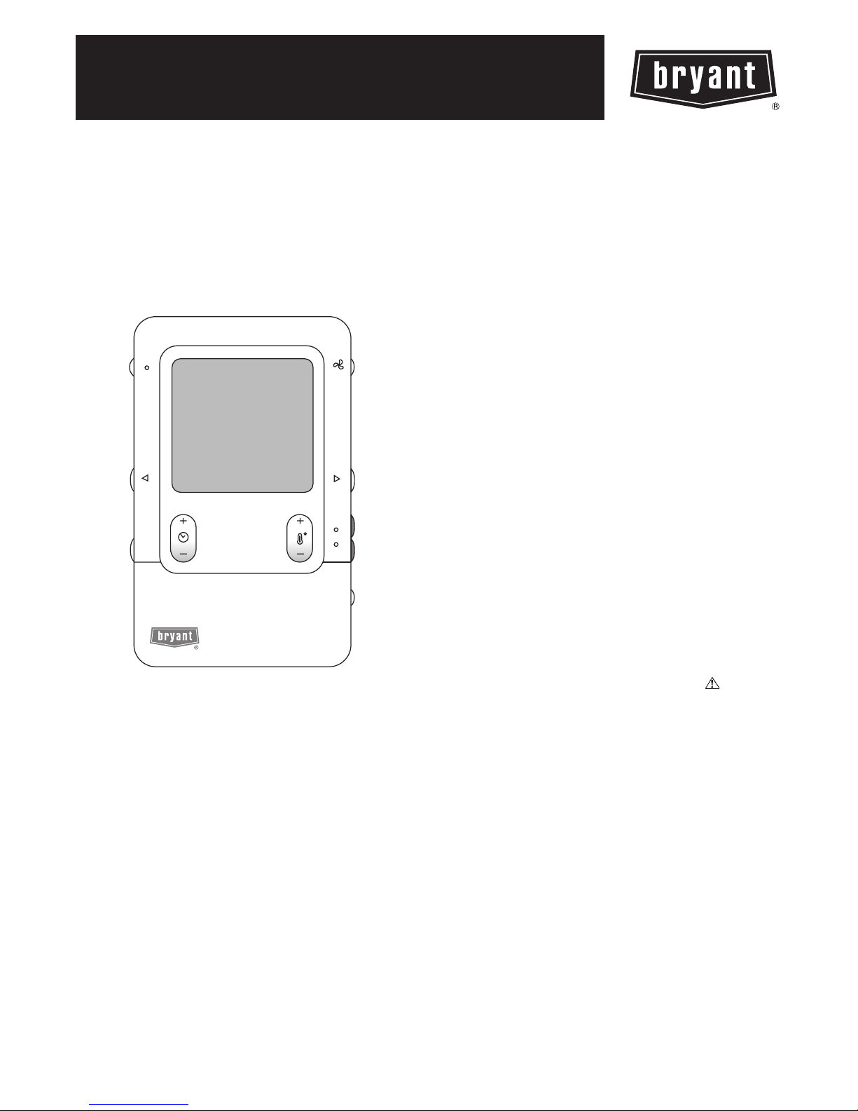
Fig. 1 -- Evolutiont Zone Control
HEAT
COOL
OFF
A04032
NOTE: Read the entire instruction manual before starting the
installation.
TABLE OF CONTENTS
PAGE
SAFETY CONSIDERATIONS 1.........................
INTRODUCTION 2...................................
INSTALLATION AND START--UP OVERVIEW 2..........
INSTALLATION 2....................................
INSTALLING EVOLUTION ZONE CONTROL 5...........
INITIAL POWER--UP 6................................
QUICK START 8.....................................
INSTALL / SERVICE MENUS 9.........................
EQUIPMENT SUMMARY MENU 9......................
INSTALL MENU 9....................................
SETUP MENU 9......................................
CHECKOUT MENUS 13...............................
SERVICE MENUS 14..................................
OPERATIONAL INFORMATION 16.....................
TROUBLESHOOTING 18..............................
SYSTEM MALFUNCTION SCREEN 19..................
SAFETY CONSIDERATIONS
Read and follow manufacturer instructions carefully. Follow all
local electrical codes during installation. All wiring must conform
to local and national electrical codes. Improper wiring or
installation may damage the Evolution Zone System. Recognize
safety information. This is the safety--alert symbol
see this symbol on the equipment and in the instruction manual, be
alert to the potential for personal injury. Understand the signal
words DANGER, WARNING, and CAUTION.
These words are used with the safety--alert symbol. DANGER
identifies the most serious hazards, which will result in severe
personal injury or death. WARNING signifies a hazard, which
could result in personal injury or death. CAUTION is used to
identify unsafe practices, which may result in minor personal
injury or product and property damage. NOTE is used to highlight
suggestions which will result in enhanced installation, reliability, or
operation.
. When you
INTRODUCTION
The Evolution Zone System consists of several intelligent
communicating components which includes the Evolution Zone
Control (or User Interface), Smart Sensors, Damper Control
Module, variable speed furnace or FE fan coil, 2--stage AC or HP
and Evolution Packaged Products, which continually communicate
with each other via a four--wire connection called the ABCD bus.
Commands, operating conditions, and other data are passed
continually between components over the ABCD bus. The result is
a new level of comfort, versatility, and simplicity.
All Evolution furnaces or fan coils are variable--speed and
multi--stage for maximum flexibility, efficiency, and comfort. They
support controlled ventilation, humidification, dehumidification,
and air quality control. Either an Evolution 2--stage
(communicating), or a standard 24VAC controlled outdoor unit
may be used.
When using conventional outdoor units, the Evolution furnace or
fan coil provides the 24 volt signals needed to control them. Also,
the Evolution Damper Control Module (P/N SYSTXBB4ZC01)
allows connection of a Bryant HRV or ERV without the need for a
separate wall control.
All system components are controlled through the wall mounted
BBUIZ01--B
Evolution Zone Control, which replaces the conventional
thermostat and provides the homeowner with a single wall control
for all features of the system.
Design Considerations
The Evolution Zone system is unique because a bypass damper
must not be used. This is possible due to the intelligence of the
system and variable speed motor technology. For trouble--free
applications, the following parameters should always be met:
1. Zones should be sized so that each zone can deliver at least
the minimum airflow for the system in both heating and
cooling modes.
2. Oversize duct work by 25% to avoid excess noise at minimum zone airflow.
3. Be aware that heating airflow may be higher than cooling
airflow depending on equipment combination.
INSTALLATION AND START--UP
OVERVIEW
This instruction covers installation of the Evolution Zone Control
only. Physical installation instructions for the indoor and outdoor
equipment, Damper Control Module, and accessories are provided
with each unit.
Setup, commissioning, operation, and troubleshooting of the
Evolution Zone System are covered in this installation instruction.
It is the guide to connecting the system components and
commissioning the system once all physical components are
installed. Special screen prompts and start--up capabilities are
provided in the Evolution System to simplify and automate the
initial commissioning of the system.
S Install Evolution Zone Control according to this instruc-
tion.
S Install indoor unit, outdoor unit, and accessories accord-
ing to their instructions.
S Wire complete system according to this instruction.
S Setup, commission, and operate system according to this
instruction to assure a smooth and trouble free start--up.
INSTALLATION
Check Equipment and Job Site
Inspect equipment. File claim with shipping company prior to
installation if shipment is damaged or incomplete.
Evolution Zone Control Location and Wiring
Considerations
!
WARNING
ELECTRICAL OPERATION HAZARD
Failure to follow this warning could result in personal injury
or death.
Disconnect power before routing control wiring.
All wiring must comply with national, local, and state codes.
Evolution Zone Control
The Evolution Zone Control User Interface is the command center
for the Evolution Zone System and is typically located in Zone 1 to
sense and control temperature in this zone. It should be located
where it is easily accessible and visible to the adult homeowner or
end user.
For accurate temperature measurement, the following guidelines
should be followed:
The Evolution Zone Control and Room Sensors should be
mounted:
S Approximately 5 feet (1.5 meters) from the floor.
S Close to or in a frequently used room, preferably on an
inside partitioning wall.
S On a section of wall without pipes or ductwork.
The Evolution Zone Control and Room Sensors should NOT be
mounted:
S Close to a window, on an outside wall, or next to a door
leading to the outside.
S Exposed to direct light or heat from a lamp, sun, fire-
place, or other temperature-- radiating objects which
could cause a false reading.
S Close to or in direct airflow from supply registers.
S In areas with poor air circulation, such as behind a door
or in an alcove.
Remote Room Sensor
A Remote Room Sensor can be used with the Evolution Zone
Control to take the place of the User Interface internal temperature
sensor. This allows the Evolution Zone Control to be mounted in
areas with less than optimal airflow (such as near an exterior door,
window or in a closet). The remote sensor can be wired to the
terminal block connectors labeled S1 and S2 at the User Interface
backplate, or the OS1 and OS1C connection at the Damper Control
Module. In either case, the Evolution Zone Control will
automatically detect the Remote Room Sensor and ignore its
internal temperature sensor. It is also important to note the
humidity sensor cannot be remotely located, so do not locate the
Evolution Zone Control in an area where humidity sensing may
not be accurate.
NOTE: S1 & S2 connection on User Interface backplate is now
used for Remote Room Sensor, NOT for OAT Sensor hookup.
In addition, the Remote Room Sensor is a temperature sensor only,
having no additional user inputs. This sensor is typically connected
to the Damper Control Module and used to sense and control
temperature in each zone.
Location
Option
2
Remote Sensor A
veraging
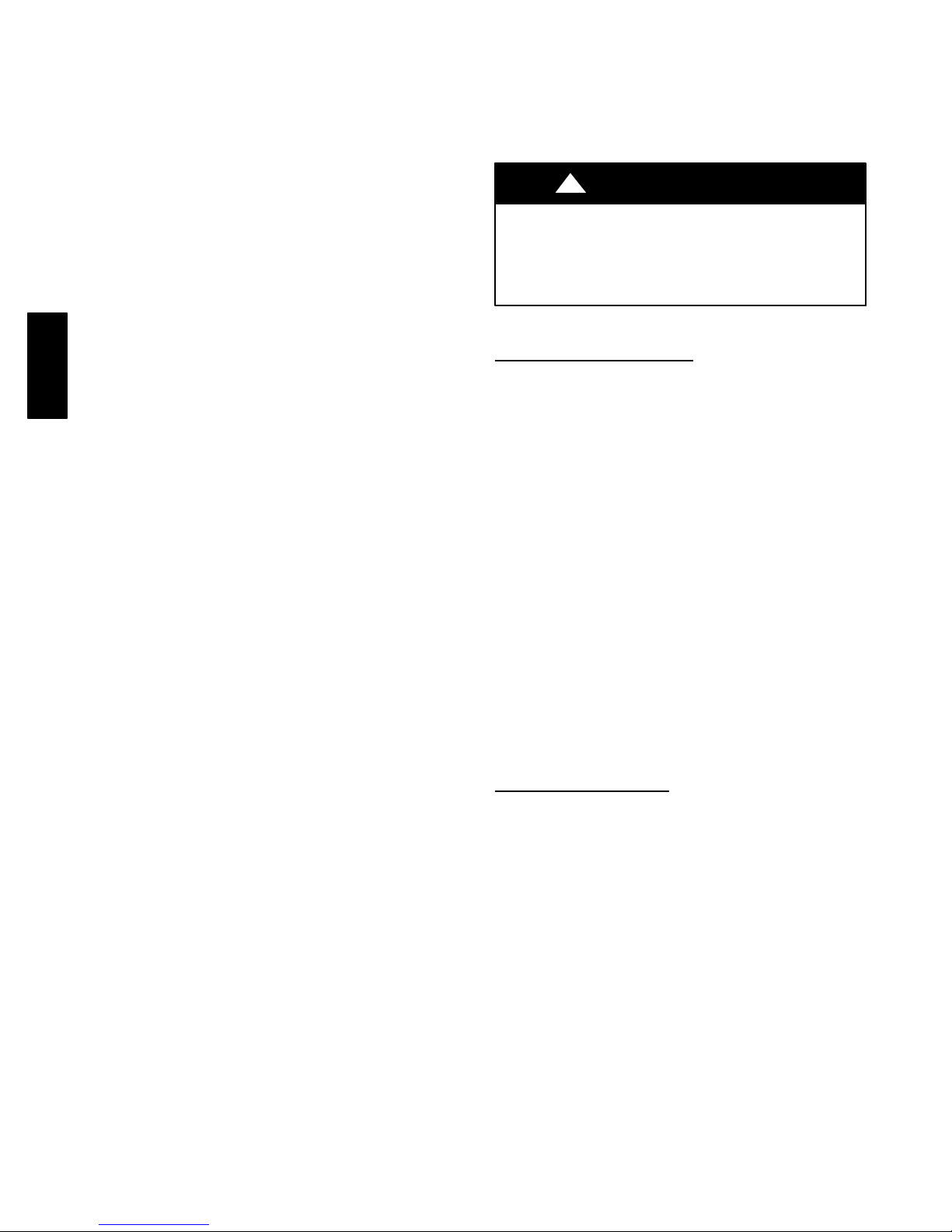
Typically, one Remote Room Sensor is used per zone, but multiple
sensors may be used and averaged in some applications. Averaging
requires a special series--parallel wiring method with a specific
number of sensors. See Fig. 2 in this manual for wiring diagram.
Damper Control
Module
ZS_
Sensor 1 Sensor 2
Sensor 3 Sensor 4
Damper Control
Module
ZS_C
A03233
Fig. 2 -- Remote Room Sensor -- Parallel Wiring
Sensor
Smart
Any zone may use a Smart Sensor. It provides a temperature
display and buttons to adjust the desired temperature in that zone
only. It also displays outdoor temperature and indoor humidity
sensed at the User Interface. Only one Smart Sensor may be used
per zone. They cannot be averaged like Remote Room Sensors. If a
Smart Sensor is used in a zone, a Remote Room Sensor may also
be used in the same zone. The Remote Room Sensor has priority
over the Smart Sensor. The Smart Sensor will display the Remote
Room Sensor temperature.
NOTE: Smart Sensors must be addressed to identify which zone it
will control. See Smart Sensor Installation Instructions for details.
Considerations
Wiring
Ordinary thermostat wire is recommended. Use 22 AWG or larger
for normal wiring applications. Continuous wire lengths over 100
ft. should use 20 AWG or larger.
NOTE: ABCD bus wiring only requires a four--wire connection;
however, it is good practice to run thermostat cable having more
than four wires in the event of a damaged or broken wire during
installation.
Each communicating device in the Evolution Zone System has a
four--pin connector labeled ABCD. It is recommended that the
following color code be used when wiring each device:
A — Green = Data A
B — Yellow = Data B
C — White = 24VAC (Com)
D — Red = 24VAC (Hot)
It is not mandatory that the above color code be used, but each
ABCD connector in the system MUST be wired consistently.
Locating Damper Control Module
All wiring is run back to the Damper Control Module. Select a
location near the furnace or fan coil where wiring from the User
Interface, each Remote Room Sensor or Smart Sensor, each
damper actuator, and the equipment itself can come together easily.
The Damper Control Module is approved for indoor use only and
should never be installed with any of its components exposed to
the elements. The Damper Control Module (and zone dampers)
may be installed in any area where the temperature remains
between --4_F to 158_F(--20_Cto70_C), and there is no
condensation. The cover must be installed to prevent damage from
other sources. Do not locate where it will be accessible to children.
It may be mounted in either vertical or horizontal position.
Remember that wiring access is likely the most important
consideration.
!
CAUTION
ELECTRICAL OPERATION HAZARD
Failure to follow this caution may result in equipment damage
or improper operation.
To prevent possible damage to the Damper Control Module,
DO NOT mount on plenum, ductwork, or flush against
furnace or fan coil.
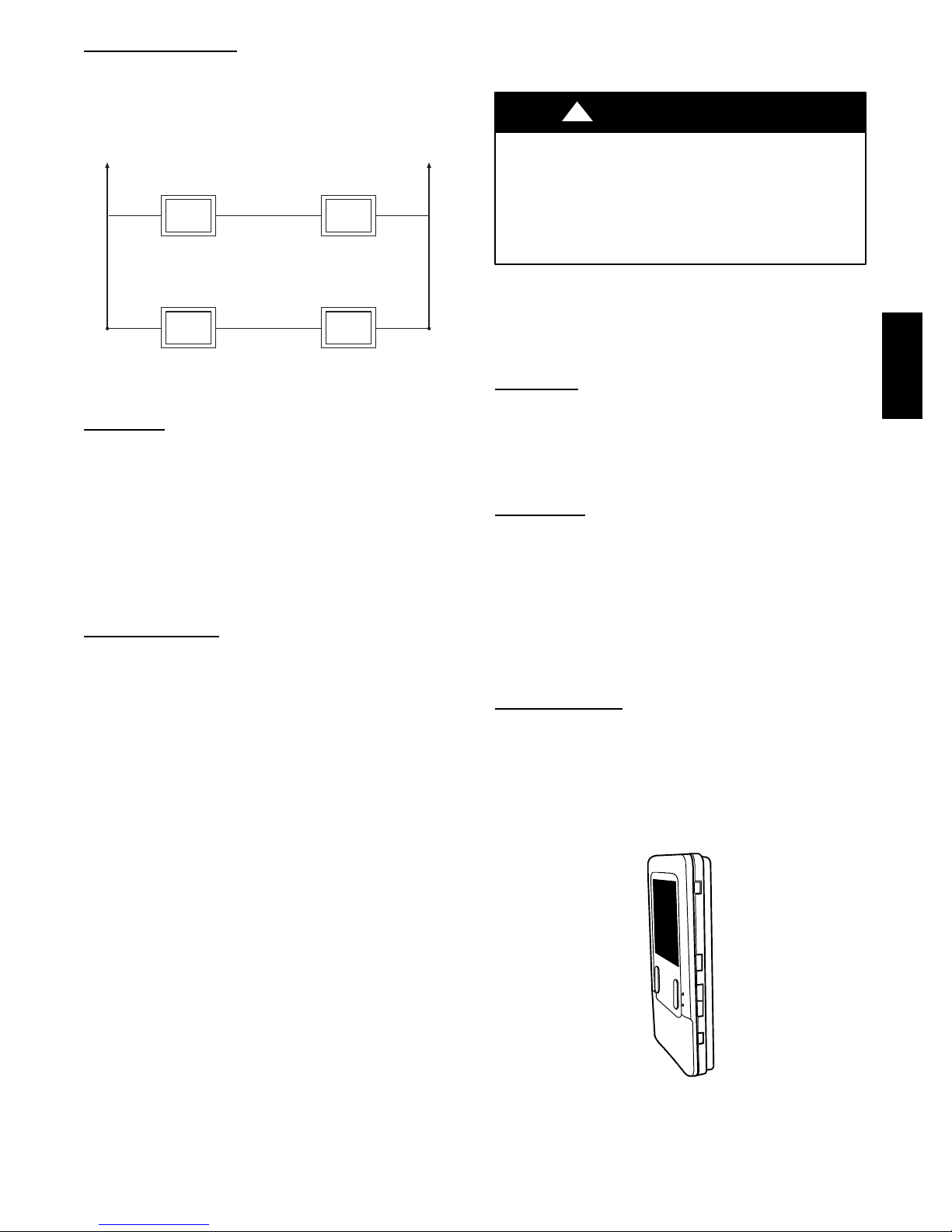
Mounting Evolution Zone Control
There are two options for mounting the Evolution Zone Control to
the wall. First, become familiar with all plastic assembly pieces
shown in Fig. 3 through 10. The User Interface will snap together
with either the Recess Mount or the Surface Mount backplate.
Mount
Recess
This provides the thinnest mounting configuration (See Fig. 4).
The backplate containing the recessed terminal block can be
mounted directly to the wall by cutting a hole 1 1/2” (38.1 mm)
wide by 2 1/8” (54 mm) high. Mark location and cut hole in wall.
NOTE: Always ensure the Evolution Zone Control location is
acceptable before cutting any holes in wall.
Surface
This provides surface mounting configuration, which allows use of
a small hole in the wall. A surface mount backplate is supplied (See
Fig. 5). Attach backplate as shown in Fig. 8, and the assembly will
mount directly to the wall requiring only a small hole in the wall
allowing a four wire connection to pass through.
NOTE: Once Evolution Zone Control is secured to wall with the
backplate assembly (snapped together), care must be taken not to
bend or break the interlocking tabs when removing. Gently remove
Evolution Zone Control by rocking up/down until interlocking
tabs release.
Decorative Backplate
Supplied is a thin decorative backplate (see Fig. 6) to hide any
marks/screw holes left from the previous thermostat. This
decorative backplate (or beauty ring) can be used in either the
recess or surface mount installation by snapping it onto back of
recessed mount backplate or surface mount backplate before
securing to wall. See Fig. 9 and 10 for a larger decorative backplate
P/N SYSTXXOLBP01 (5.75” / 146 mm wide x 6” / 15 2 mm
high), which can be ordered separately.
Mount
A03185
Fig. 3 -- Evolutiont Zone Control
BBUIZ01--B
3
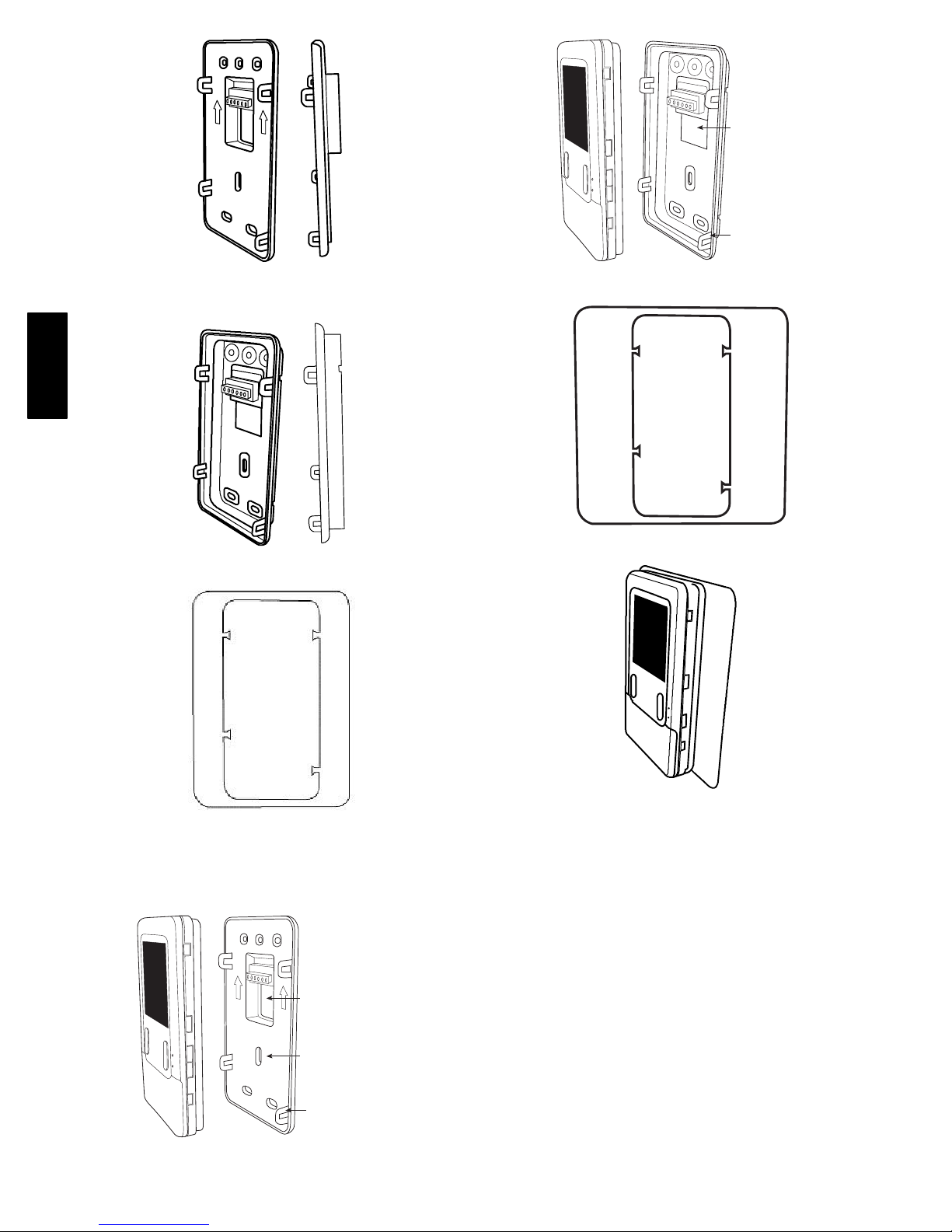
Surface Mount
Backplate to wall
Interlocking Tabs (4)
Fig. 4 -- Recessed Mount Backplate
A03186
Fig. 8 -- Surface Mount Assembly
A03191
BBUIZ01--B
A03188
A03187
Fig. 5 -- Surface Mount Backplate
Fig. 9 -- Large Decorative Backplate
Fig. 6 -- Thin Decorative Backplate
Recessed terminal
block in wall 1
wide by 2
Recessed Mount
Interlocking Tabs (4)
Fig. 7 -- Recessed Mount Assembly
1
" (38.1 mm)
/
2
1
/8" (54 mm) high
A04017
A07150
A03192
Fig. 10 -- Decorative Backplate Assembly
4
INSTALLING EVOLUTION ZONE
CONTROL
!
WARNING
ELECTRICAL SHOCK HAZARD
Failure to follow this warning could result in personal injury
or death.
Before installing Evolution Zone Control, turn off all power
to equipment. There may be more than one power source to
disconnect.
1. Turn off all power to equipment.
2. If an existing User Interface or control is being replaced:
a. Remove existing control from wall.
b. Disconnect wires from existing control.
c. Discard or recycle old control.
NOTE: Mercury is a hazardous waste, if existing control contains
any mercury, it MUST be disposed of properly. The User Interface
does not contain mercury.
3. Select Evolution Zone Control mounting plastic (recess
mount or surface mount and decorative backplate if desired).
4. Route wires through large hole in mounting plastic. Level
rear plastic against wall (for aesthetic value only -- Evolution Zone Control need not be level to operate properly) and
mark wall through two mounting holes.
5. Drill two 3/16” (4.8 mm) mounting holes in wall where
marked.
6. Secure mounting plastic to wall using two screws and anchors provided.
7. Adjust length and routing of each wire to reach each wire
entry on the connector backplate. Strip 1/4” (6.4 mm) of insulation from each wire.
8. Match and connect thermostat wires to proper terminals on
User Interface backplate. See wiring diagram Fig. 12, 13,
and 14.
A — Green = Data A
B — Yellow = Data B
C — White = 24VAC (Com)
D — Red = 24VAC (Hot)
NOTE: It is not mandatory that the above color code be used, but
each ABCD connection in the system MUST be wired consistently.
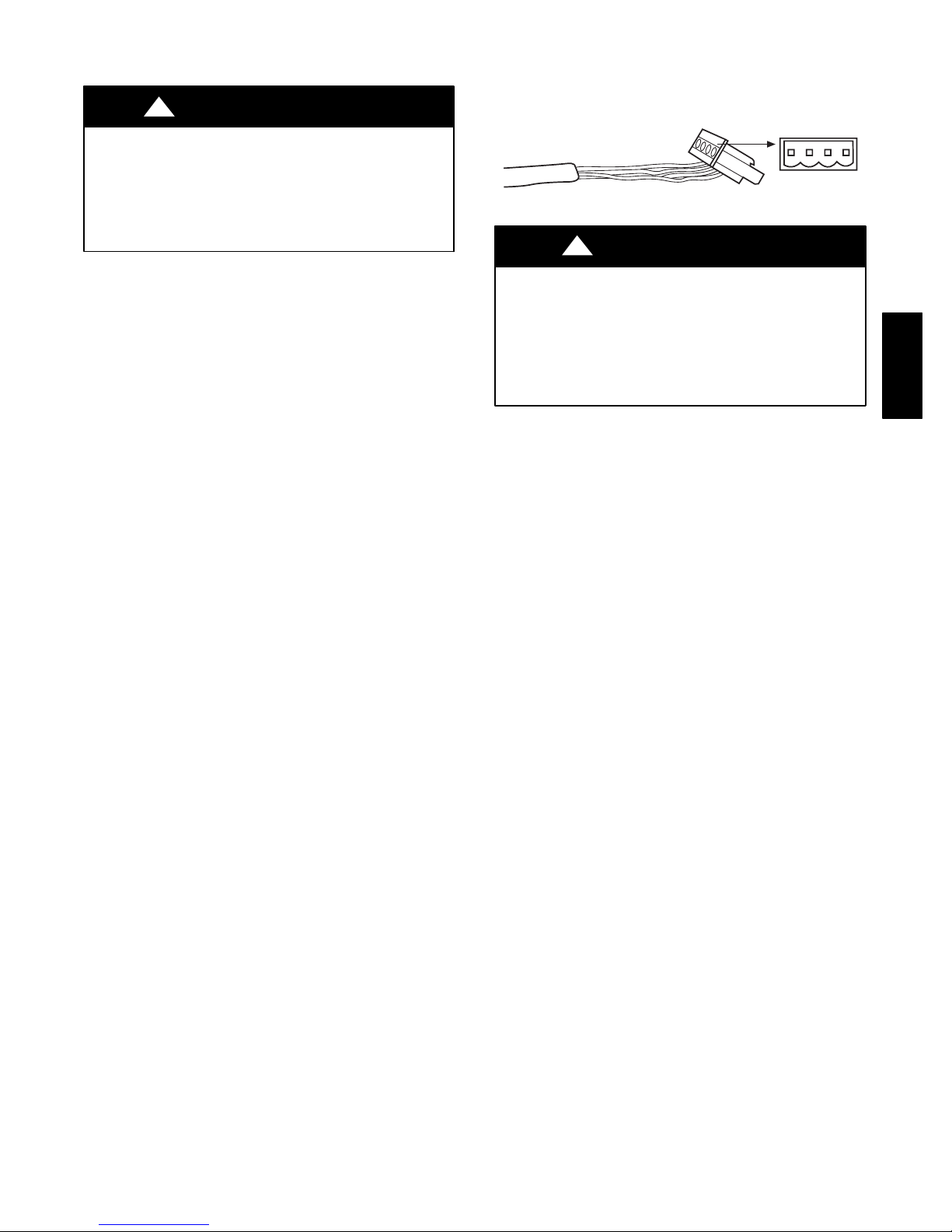
A separate ABCD Connector comes inside packaging and should
be used when connecting to furnace (or fan coil). Ensure connector
is inserted properly into circuit board. (See Fig. 11.)
ABCD
A03193
Fig. 11 -- Wire ABCD Connector
!
CAUTION
ELECTRICAL OPERATION HAZARD
Failure to follow this caution may result in equipment damage
or improper operation.
Improper wiring of the ABCD connector will cause the
Evolution Zone System to operate improperly. Check to make
sure all wiring is correct before proceeding with installation or
turning on power.
9. Push any excess wire into the wall. Seal hole in wall to prevent any air leaks. Leaks can affect operation.
10. Attach Evolution Zone Control to the mounting plastic by
lining up the plastic guides on the back of the control with
the opening on the mounting plastic and push on.
11. Perform installation of all other system equipment (i.e.
dampers, humidifier, ventilator, UV lights, etc.)
12. Turn on power to equipment.
See wiring diagrams Fig. 12, 13, and 14 for connecting the
Evolution Zone Control and Smart Sensors to the Damper Control
Module. More information regarding Damper Control set--up and
wiring can be found in Damper Control Module Installation
Instructions.
See wiring diagram, Fig. 12, which includes an indoor
communicating furnace or FE fan coil, with a 2--stage Puronr
refrigerant communicating outdoor unit. No additional OAT
(outdoor air temperature) sensor is required because the Evolution
Zone Control will use the temperature sensor inside the outdoor
unit.
See wiring diagram, Fig. 13, for connecting an indoor
communicating furnace or FE fan coil with a 1--stage air
conditioning unit (non--communicating outdoor). An Outdoor Air
Temperature (OAT) sensor may be installed (but is not required) at
the indoor furnace or fan coil OAT terminals. When OAT sensor is
applied, the Evolution System will provide enhanced system
features and benefits.
See wiring diagram Fig. 14 for connecting an FE fan coil with a
1-- stage heat pump (non--communicating outdoor unit). When
OAT is applied, the Evolution System will provide enhanced
system features and benefits.
NOTE: For other applications not listed, refer to the Network
Interface Module (NIM) Installation Instructions.
BBUIZ01--B
5
Zone Control
User Interface &
Smart Sensor(s)
A B C D
Indoor
Green
Yellow
White
Red
Unit
A
B
C
D
Communicating
A B C D A B C D
HUM
COM
24V
OAT
(Optional)
Damper
Control
module
Humidifier
Connection
Fig. 12 -- Communicating Indoor Unit w/2--Stage Puronr
Refrigerant Communicating Outdoor Unit
Indoor
Zone Control
User Interface &
Smart Sensor(s)
BBUIZ01--B
A B C D
A B C D A B C D
Damper
Control
Green
Yellow
White
Red
Humidifier
Connection
Unit
HUM
COM
24V
Y/Y2
A
B
C
D
module
OAT
Fig. 13 -- Connection Diagram for Furnace or FE Fan Coil
with Non--Communicating 1--Stage AC
Green
Yellow
White
Red
Humidifier
Connection
Variable-Speed
Fan Coil
A
B
C
D
HUM
C
G
R
O
W
Y
OAT
Zone Control
User Interface &
Smart Sensor(s)
A B C D
A B C D A B C D
Damper
Control
module
Fig. 14 -- Connection Diagram for FE Fan Coil with
Non-- Communicating 1--stage HP
Humidifier Connection
A 24VAC bypass or fan powered humidifier may be installed.
NOTE: Do Not Use a traditional humidistat to control humidifier
operation. If a humidifier is installed, let the Evolution Zone
Control operate humidifier.
AC or HP
A
B
C
D
OAT
Sensor
1-Stage AC.
1-Spd. HP
A04018
C
Y
OAT
Sensor
A04019
Sensor
A07149
OAT
Bypass
Humidifiers
A bypass humidifier should be wired directly to the furnace or fan
coil HUM and 24VAC COM terminals. The Evolution Zone
Control will automatically energize the HUM output during a call
for humidification.
Fan Powered
Humidifiers
Most fan powered humidifiers produce internal 24VAC in order to
energize upon a switch or contact closure. For this application, a
24VAC N.O. Isolation Relay (DPST) MUST be used to prevent
mixing the internal humidifier power with the indoor equipment
transformer. Applying 24VAC isolation relay coil to furnace or fan
coil HUM and COM terminals will allow the Evolution Zone
Control to automatically energize the HUM output during a call for
humidification. The N.O. relay contacts will be used to energize the
humidifier. See fan powered humidifier installation instructions for
more details.
!
CAUTION
EQUIPMENT HAZARD
Failure to follow this caution may result in equipment damage.
Do not apply 24VAC fan powered humidifier (with internal
power supply) direct to indoor unit HUM and COM terminals.
INITIAL POWER--UP
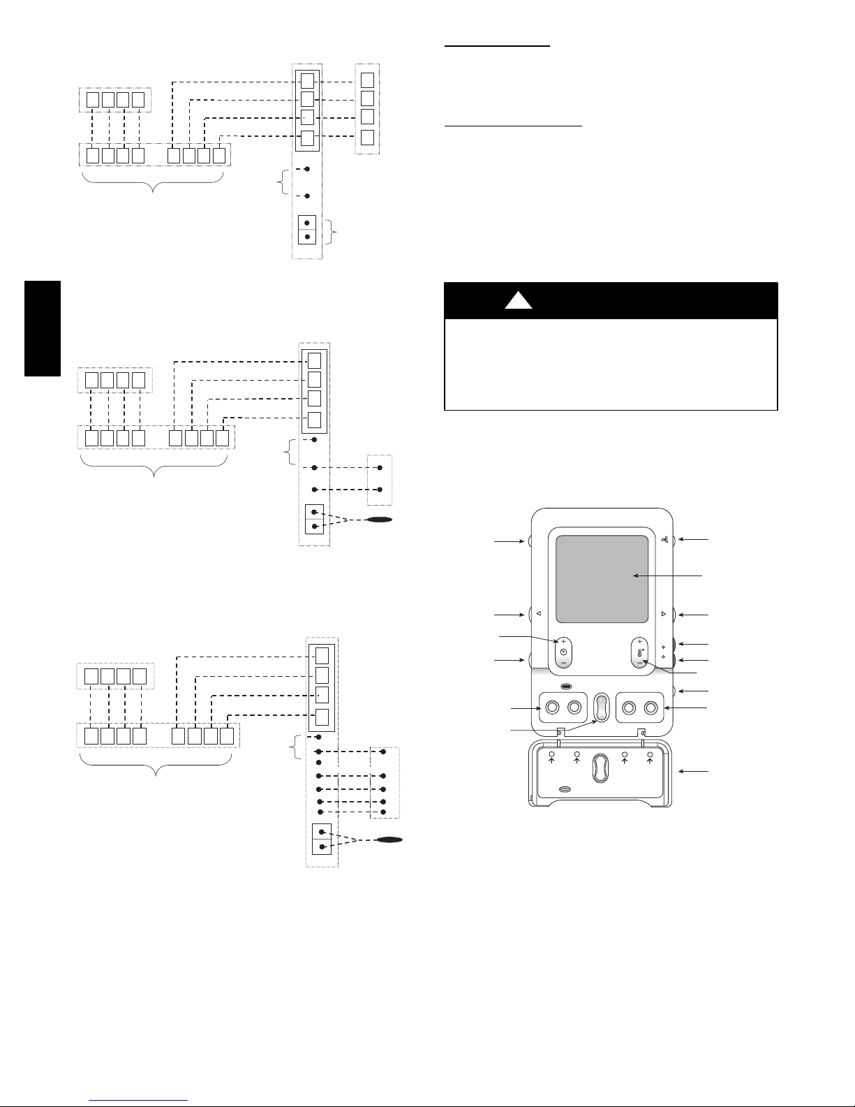
NOTE: Refer to Functional Overview (Fig. 15) to become
familiar with key function buttons such as “System On/Off”,
“Zone”, “Fan”, “Left--Side” and “Right--Side” buttons, etc. These
function buttons will be used frequently during setup.
Zone
Button
Left-Side
Button
Time (+/-)
Button
Hold
Button
Schedule & Vacation
Program Buttons
Up/Down
C
R
O
W2
Y
Scroll Buttons
ZONE
HOLD
SCHEDULE VACATION
PROGRAM
Schedule
to program
temperature
schedule
Vacation
to start/end
vacation
SCROLL
Scroll
up & down
BASIC
Basic
to set time,
humidity
SETUPS
ADVANCED
Advanced
for all other
settings
HEAT
COOL
Fig. 15 -- Functional Overview
Power Up Sequence
This section addresses initial power up (or commissioning) of a
new Evolution Zone Control. The User Interface will communicate
and identify all Evolution components in the system. The
following is a typical example for a communicating
Variable--Speed Furnace / Fan Coil with a 2 --stage Air Conditioner
/ Heat Pump (including Hybrid Heat).
The User Interface display will light up and indicate that it is now
“ESTABLISHING COMMUNICATIONS WITH EQUIPMENT
PLEASE WAIT”. The User Interface will automatically continue
by “SEARCHING FOR EQUIPMENT”, followed by
“SEARCHING FOR OUTDOOR EQUIPMENT” (See Fig. 16).
Fan Button
Display Screen
(LCD)
Right-Side
Button
Heat Button
Cool Button
Temperature
(+/-) Button
System
On/Off Button
Basic & Advanced
Setup Buttons
Flip Down
Door
A04038
6
 Loading...