

Page 1
286A / 288A
Evolutiont Series Heat Pumps with Puronr Refrigerant
2 To 5 Nominal Tons (Sizes 024 to 060)
Installation Instruction
NOTE: Read the entire instruction manual before starting the
installation.
Unless otherwise noted, information in these installation
instructions pertain to both 286A and 288A series units.
Information that is unique to the 286A series will be identified as
such; likewise information that is unique to the 288A series will
also be identified.
SAFETY CONSIDERATIONS
Improper installation, adjustment, alteration, service, maintenance,
or use can cause explosion, fire, electrical shock, or other
conditions which may cause death, personal injury, or property
damage. Consult a qualified installer, service agency, or your
distributor or branch for information or assistance. The qualified
installer or agency must use factory--authorized kits or accessories
when modifying this product. Refer to the individual instructions
packaged with the kits or accessories when installing.
Follow all safety codes. Wear safety glasses, protective clothing,
and work gloves. Use quenching cloth for brazing operations.
Have fire extinguisher available. Read these instructions
thoroughly and follow all warnings or cautions included in
literature and attached to the unit. Consult local building codes and
current editions of the National Electrical Code ( NEC ) NFPA 70.
In Canada, refer to current editions of the Canadian electrical code
CSA 22.1.
Recognize safety information. This is the safety--alert symbol
When you see this symbol on the unit and in instructions or
manuals, be alert to the potential for personal injury. Understand
these signal words; DANGER, WARNING, and CAUTION. These
words are used with the safety--alert symbol. DANGER identifies
the most serious hazards which will result in severe personal injury
or death. WARNING signifies hazards which could result in
personal injury or death. CAUTION is used to identify unsafe
practices which would result in minor personal injury or product
and property damage. NOTE is used to highlight suggestions
which will result in enhanced installation, reliability, or operation.
Indoor Thermostat Control Options
Model
286A Yes Yes
288A Yes Yes*
* Units containing circuit board HK38EA015 or newer.
!
ELECTRICAL SHOCK HAZARD
Failure to follow this warning could result in personal
injury or death.
Before installing, modifying, or servicing system, main
electrical disconnect switch must be in the OFF position
and install a lockout tag. There may be more than 1
disconnect switch. Lock out and tag switch with a
suitable warning label.
!
!
!
UNIT OPERATION AND SAFETY HAZARD
Failure to follow this warning could result in personal injury
or equipment damage.
PuronR refrigerant systems operate at higher pressures than
standard R--22 systems. Do not use R--22 service equipment
or components on PuronR refrigerant equipment.
Evolution
Control
WARNING
WARNING
Standard
2 --- s ta g e
Thermostat
!
CAUTION
CUT HAZARD
Failure to follow this caution may result in personal injury.
Sheet metal parts may have sharp edges or burrs. Use care and
wear appropriate protective clothing and gloves when handling
parts.
Page 2
INSTALLATION RECOMMENDATIONS
NOTE: In some cases noise in the living area has been traced to
gas pulsations from improper installation of equipment.
1. Locate unit away from windows, patios, decks, etc. where
unit operation sound may disturb customer.
2. Ensure that vapor and liquid tube diameters are appropriate
for unit capacity.
3. Run refrigerant tubes as directly as possible by avoiding unnecessary turns and bends.
4. Leave some slack between structure and unit to absorb vibration.
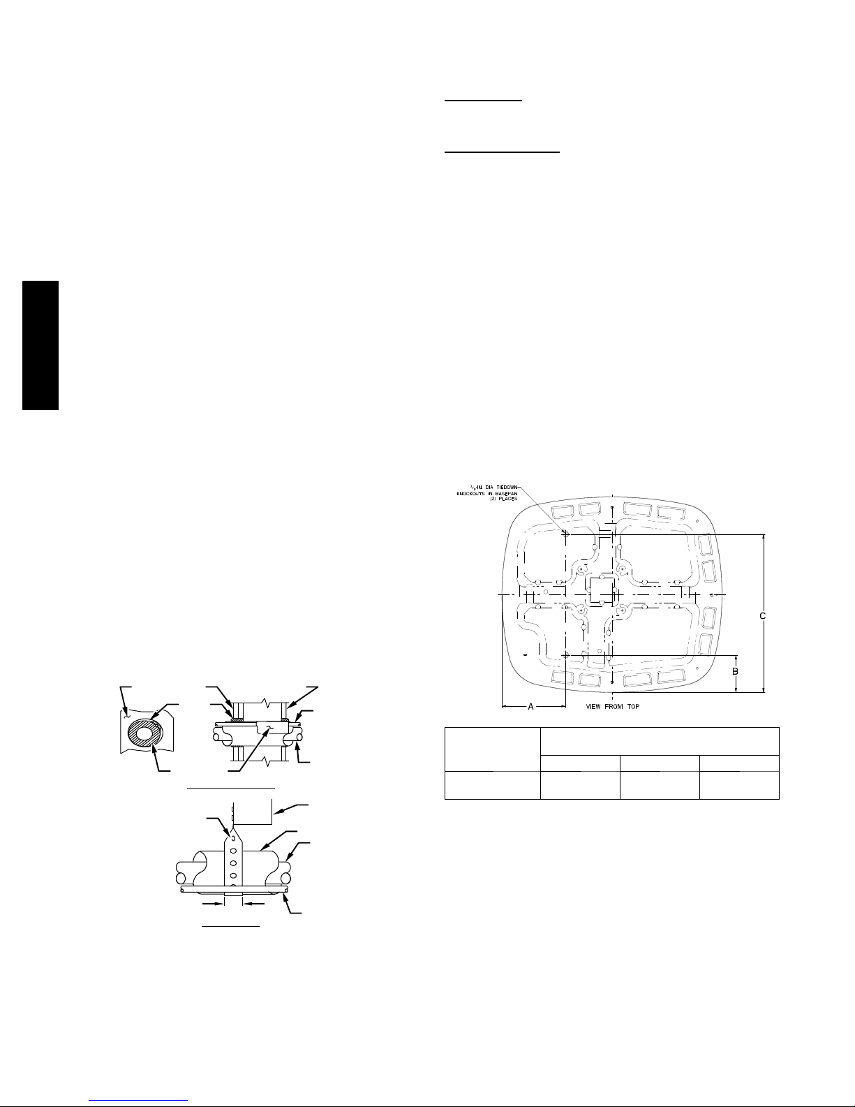
5. When passing refrigerant tubes through the wall, seal opening with RTV or other pliable silicon --based caulk. (See Fig.
1.)
6. Avoid direct tubing contact with water pipes, duct work,
floor joists, wall studs, floors, and walls.
7. Do not suspend refrigerant tubing from joists and studs with
a rigid wire or strap which comes in direct contact with
tubing.(See Fig. 1.)
8. Ensure that tubing insulation is pliable and completely surrounds vapor tube.
286A / 288A
9. When necessary, use hanger straps which are 1 in. wide and
conform to shape of tubing insulation. (See Fig. 1.)
10. Isolate hanger straps from insulation by using metal sleeves
bent to conform to shape of insulation.
When outdoor unit is connected to factory--approved indoor unit,
outdoor unit contains system refrigerant charge for operation with
ARI rated indoor unit when connected by 15 ft. (4.57 m) of
field--supplied or factory accessory tubing. For proper unit
operation, check refrigerant charge using charging information
located on control box cover and/or in the Check Charge section of
this instruction.
IMPORTANT: Maximum liquid-- line size is 3/8--in. OD for all
residential applications including long line applications.
IMPORTANT: Always install the factory--supplied liquid--line
filter drier. Obtain replacement filter driers from your distributor or
branch.
required unit changes for specific applications and for R-- 22
retrofit.
Check Equipment and Job Site
Unpack Unit
Move to final location. Remove carton taking care not to damage
unit.
Inspect Equipment
File claim with shipping company prior to installation if shipment
is damaged or incomplete. Locate unit rating plate on unit corner
panel. It contains information needed to properly install unit.
Check rating plate to be sure unit matches job specifications.
Install on a Solid, Level Mounting Pad
If conditions or local codes require the unit be attached to pad, tie
down bolts should be used and fastened through knockouts
provided in unit base pan. Refer to unit mounting pattern in Fig. 2
to determine base pan size and knockout hole location.
For hurricane tie downs, contact distributor for details and PE
(Professional Engineer)Certification, if required.
On rooftop applications, mount on level platform or frame. Place
unit above a load-- bearing wall and isolate unit and tubing set from
structure. Arrange supporting members to adequately support unit
and minimize transmission of vibration to building. Consult local
codes governing rooftop applications.
Roof mounted units exposed to winds above 5 mph may require
wind baffles. Consult the Service Manual -- Residential Split
System Air Conditioners and Heat Pumps Using Puron®
Refrigerant for wind baffle construction.
INSTALLATION
Avoid contact between tubing and structureNOTE:
OUTDOOR WALL
CAULK
INSULATION
HANGER STRAP
(AROUND VAPOR
TUBE ONLY)
1” (25.4 mm) MIN.
THROUGH THE WALL
INDOOR WALL
SUSPENSION
LIQUID TUBE
VAPOR TUBE
JOIST
INSULATION
VAPOR TUBE
LIQUID TUBE
A94028
Fig. 1 -- Connecting Tube Installation
Specifications for this unit in residential new construction market
require the outdoor unit, indoor unit, refrigerant tubing sets,
metering device, and filter drier listed in presale literature. There
can be no deviation. Consult the Service Manual – Air
Conditioners and Heat Pumps Using Puron® Refrigerant to obtain
UNIT BASE PAN
DIMENSIONS
in. (mm)
36--- 1/2 x 40
(927.1x10¹⁶)
TIEDOWN KNOCKOUT LOCATIONS
A B C
11--- 5/8
(295.3)
in. (mm)
6--- 13/16
(173.0)
28--- 3/4
(730.3)
A05242
Fig. 2 -- Tiedown Knockout Locations
NOTE: Unit must be level to within ±2° (±3/8 in./ft. / ±9.53
mm/m) per compressor manufacturer specifications.
Clearance Requirements
When installing, allow sufficient space for airflow clearance,
wiring, refrigerant piping, and service. Allow 24 in. (610 mm)
clearance to service end of unit and 48 in. (1219.2 mm) above unit.
For proper airflow, a 6 in. (152.4 mm) clearance on 1 side of unit
and 12 in. (304.8 mm) on all remaining sides must be maintained.
Maintain a distance of 24 in. (609.6 mm) between units. Position
so water, snow, or ice from roof or eaves cannot fall directly on
unit.
On rooftop applications, locate unit at least 6 in. (152.4 mm) above
roof surface.
2
Page 3
Operating Ambient
The minimum outdoor operating ambient in cooling mode is
55_F/12.78_C without low ambient cooling enabled, and the
maximum outdoor operating ambient in cooling mode is
125_F/51.67_C. On Evolution communicating systems only (for
both 286A and 288A), low ambient cooling is available to
0_F/--17.78_C.
The maximum outdoor operating ambient in heating mode is
66°F/18.89_C on all models.
Elevate Unit
Make Piping Connections
!
PERSONAL INJURY AND UNIT DAMAGE
HAZARD
Failure to follow this warning could result in personal
injury or death.
Relieve pressure and recover all refrigerant before system
repair or final unit disposal. Use all service ports and open
all flow--control devices, including solenoid valves.
WARNING
!
UNIT OPERATION HAZARD
Failure to follow this caution may result in equipment
damage or improper operation.
Do not allow water and/or ice to build up in base pan.
Elevate unit per local climate and code requirements to provide
clearance above estimated snowfall level and ensure adequate
drainage of unit.
!
UNIT OPERATION HAZARD
Failure to follow this caution may result in equipment
damage or improper operation.
Locate the unit in such a way that it is stable in all
circumstances including adverse weather conditions.
CAUTION
CAUTION
In Long--Line Applications, Install Liquid--Line
Solenoid Valve (LSV)
For refrigerant piping arrangements with equivalent lengths greater
than 80 ft. (24.38 m) and/or when elevation difference between
indoor and outdoor unit is greater than ±20 ft. (±6.10 m), follow
all requirements of the Residential Piping and Longline Guideline.
If required by Long--Line Guideline, install LSV kit, part no.
KHALS0401LLS, specifically designed for PuronR refrigerant
heat pumps. LSV should be installed within 2 ft. (0.61 m) of
outdoor unit with flow arrow pointing toward outdoor unit. Follow
the Installation Instructions included with accessory kit.
IMPORTANT: Flow arrow must point toward outdoor unit.
!
UNIT DAMAGE HAZARD
Failure to follow this caution may result in equipment
damage or improper operation.
Do not leave system open to atmosphere any longer than
minimum required for installation. POE oil in compressor is
extremely susceptible to moisture absorption. Always keep
ends of tubing sealed during installation.
!
UNIT DAMAGE HAZARD
Failure to follow this caution may result in equipment
damage or improper operation.
If ANY refrigerant tubing is buried, provide a 6 in. vertical
rise at service valve. Refrigerant tubing lengths up to 36 in.
(914.4 mm) may be buried without further special
consideration. Do not bury lines longer than 36 in. (914.4
mm).
Outdoor units may be connected to indoor section using accessory
tubing package or field --supplied refrigerant grade tubing of correct
size and condition. For tubing requirements beyond 80 ft. (24.38
m), substantial capacity and performance losses can occur.
Following the recommendations in the Residential Piping and
Longline Guideline will reduce these losses. Refer to Table 1 for
field tubing diameters. Refer to Table 2 for accessory requirements.
CAUTION
CAUTION
Outdoor Unit Connected to Factory--Approved Indoor
Unit
Outdoor unit contains correct system refrigerant charge for
operation with factory--approved, ARI--rated indoor unit with
highest sales volume when connected by 15 ft. (4.57 m) of
field--supplied or factory-- accessory tubing, and factory--supplied
filter drier. Check refrigerant charge for maximum efficiency.
286A / 288A
3
Page 4
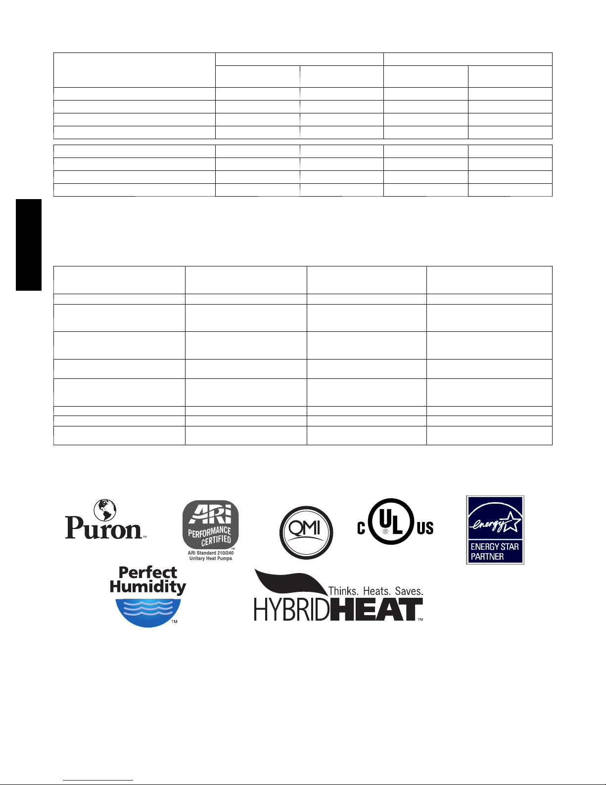
Table 1 – Refrigerant Connections and Recommended Liquid and Vapor Tube Diameters (in.)
Information is Specific to 286A and 288A Models
LIQUID RATED VAPOR*
UNIT SIZE
286A024 3/8 3/8 5/8 5/8
286A036 3/8 3/8 3/4 3/4
286A048 3/8 3/8 7/8 7/8
286A060 3/8 3/8 7/8 1--1/8
Connection
Diameter
Tube
Diameter
Connection
Diameter
Tube
Diameter
288A024
288A036
288A048
288A060
* Units are rated with 25 ft. (7.6 m) of lineset. See Product Data sheet for performance data when using different size and length linesets.
Notes:
1. Do not apply capillary tube or th e fixed orifice indoor coils to these u nits.
2 For Tubing Set lengths between 80 and 200 ft. (24.38 and 60.96 m) horizontal or 20 ft. (6.10 m) vertical differential ( 250 ft./76.2 m Total Equivalent Length),
refer to the Residential Piping and Long Line Guideline for Air Conditioners and Heat Pumps using Puron® Refrigerant.
3/8 3/8 3/4 3/4
3/8 3/8 3/4 3/4
3/8 3/8 7/8 7/8
3/8 3/8 7/8 1--1/8
Table 2 – Accessory Usage
286A / 288A
ACCESSORY
Crankcase Heater Standard
Evaporator Freeze Protection
Winter Start Control
Compressor Start Assist Capacitor
and Relay}
Low--- Ambient Control
Support Feet Recommended No Recommended
Liquid--- Line Solenoid Valve No
Puron Refrigerant Balance Port
H a r d --- S h u t O f f T X V
* For tubing set lengths between 80 and 200 ft. (24.38 and 60.96 m) horizontal or 20 ft. (6.10 m) vertical differential (total equivalent length), refer to the
Residential Piping and Long Line Guideline for Air Conditioners and Heat Pumps using Puron® Refrigerant.
{ Required on all indoor units. Standard on all new Puron refrigerant fan coils and furnace coils.
} Information is specific to 286A and 288A models.
REQUIRED FOR LOW---AMBIENT
COOLING APPLICATIONS
(Below 55°F/12.8_C)
Standard with Evolutiont Control
(Low Ambient not allowed with
non---communicating thermostat)
Standard with Evolution Control
(Low Ambient not allowed with non ---
communicating thermostat)
Standard on 286A models.
Not required for 288A
Standard with Evolution Control
(Low ambient not allowed with non ---
communicating thermostat)
Ye s {
REQUIRED FOR LONG LINE
APPLICATIONS*
Standard
No No
No No
Standard on 286A models.
Not required for 288A
No No
Yes
Ye s {
REQUIRED FOR SEA COAST
APPLICATIONS
(Within 2 miles/3.22 km)
Standard
Standard on 286A models
Not required for 288A
No
Ye s {
the environmentally sound refrigerant
ISO 9001:2000
REGISTERED
Ready for use in a Hybrid Heatr Duel Fuel system.
4
This produ ct has been desi gned and manuf actured t o
meet Energy Star® crit eria for energy efficiency when
matched with appropriate coil components. However,
proper refr igerant c harge and proper ai r flo w are crit ical
to achieve rated capacity and effi ciency. Installation of
this product should follow all manufacturing refrigerant
charging and air flow instructions. Failure to confirm
proper charge and air flow may reduce energy
efficiency and shorten equipment life.
Page 5
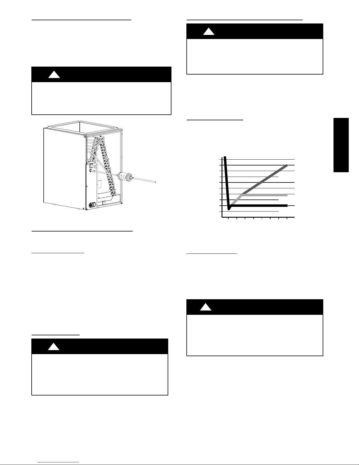
Install Liquid--Line Filter Drier Indoor
Refer to Fig. 3 and install filter drier as follows:
1. Braze 5--in. (127 mm) liquid tube to the indoor coil.
2. Wrap filter drier with damp cloth.
3. Braze filter drier to above 5-- in. (127 mm) liquid tube. Flow
arrow must point towards indoor coil.
4. Connect and braze liquid refrigerant tube to the filter drier.
!
UNIT DAMAGE HAZARD
Failure to follow this caution may result in equipment damage
or improper operation.
Installation of filter drier in liquid line is required.
CAUTION
A05227
Fig. 3 -- Liquid--Line Filter Drier
Refrigerant Tubing connection Outdoor
Connect vapor tube to fitting on outdoor unit vapor service valves
(see Table 1).
Install Adapter Tube
1. Remove plastic retainer holding outdoor piston in liquid
service valve.
2. Check outdoor piston size with matching number listed on
unit rating plate.
3. Locate plastic bag taped to unit containing adapter tube.
4. Remove TeflonR washer from bag and install on open
end of liquid service valve.
5. Remove adapter tube from bag and connect threaded nut to
liquid service valve. Tighten nut finger tight and then with
wrench tighten an additional 1/2 turn (15 ft--lb).
DO NOT OVER TIGHTEN!
Sweat Connections
!
CAUTION
Evacuate Refrigerant Tubing and Indoor Coil
!
UNIT DAMAGE HAZARD
Failure to follow this caution may result in equipment
damage or improper operation.
Never use the system compressor as a vacuum pump.
Refrigerant tubes and indoor coil should be evacuated using the
recommended deep vacuum method of 500 microns. The alternate
triple evacuation method may be used. See Service Manual for
triple evacuation method. Always break a vacuum with dry
nitrogen.
CAUTION
Deep Vacuum Method
The deep vacuum method requires a vacuum pump capable of
pulling a vacuum of 500 microns and a vacuum gauge capable of
accurately measuring this vacuum depth. The deep vacuum method
is the most positive way of assuring a system is free of air and
liquid water. (See Fig. 4)
5000
4500
4000
3500
3000
2500
2000
MICRONS
1500
1000
500
01234567
Fig. 4 -- Deep Vacuum Graph
MINUTES
LEAK IN
SYSTEM
VACUUM TIGHT
TOO WET
TIGHT
DRY SYSTEM
A95424
Final Tubing Check
IMPORTANT: Check to be certain factory tubing on both indoor
and outdoor unit has not shifted during shipment. Ensure tubes are
not rubbing against each other or any sheet metal. Pay close
attention to feeder tubes, making sure wire ties on feeder tubes are
secure and tight.
Make Electrical Connections
!
ELECTRICAL SHOCK HAZARD
Failure to follow this warning could result in personal
injury or death.
Do not supply power to unit with compressor terminal box
cover removed.
WARNING
286A / 288A
UNIT DAMAGE HAZARD
Failure to follow this caution may result in equipment
damage or improper operation.
S Use a brazing shield
S Wrap service valves with wet cloth or heat sink material.
Use refrigerant grade tubing. Service valves are closed from factory
and ready for brazing. After wrapping service valve with a wet
cloth, braze sweat connections using industry accepted methods
and materials. Consult local code requirements. Refrigerant tubing
and indoor coil are now ready for leak testing. This check should
include all field and factory joints.
Be sure field wiring complies with local and national fire, safety,
and electrical codes, and voltage to system is within limits shown
on unit rating plate. Contact local power company for correction of
improper voltage. See unit rating plate for recommended circuit
protection device.
NOTE: Operation of unit on improper line voltage constitutes
abuse and could affect unit reliability. See unit rating plate. Do not
install unit in system where voltage may fluctuate above or below
permissible limits.
NOTE: Use copper wire only between disconnect switch and unit.
5
Page 6
NOTE: Install branch circuit disconnect of adequate size per NEC
to handle unit starting current. Locate disconnect within sight from
and readily accessible from unit, per Section 440-- 14 of NEC.
Route Ground and Power Wires
Remove access panel to gain access to unit wiring. Extend wires
from disconnect through power wiring hole provided and into unit
control box.
!
ELECTRICAL SHOCK HAZARD
Failure to follow this warning could result in personal
injury or death.
The unit cabinet must have an uninterrupted or unbroken
ground to minimize personal injury if an electrical fault
should occur. The ground may consist of electrical wire or
metal conduit when installed in accordance with existing
electrical codes.
WARNING
Connect Ground and Power Wires
Connect ground wire to ground connection in control box for
286A / 288A
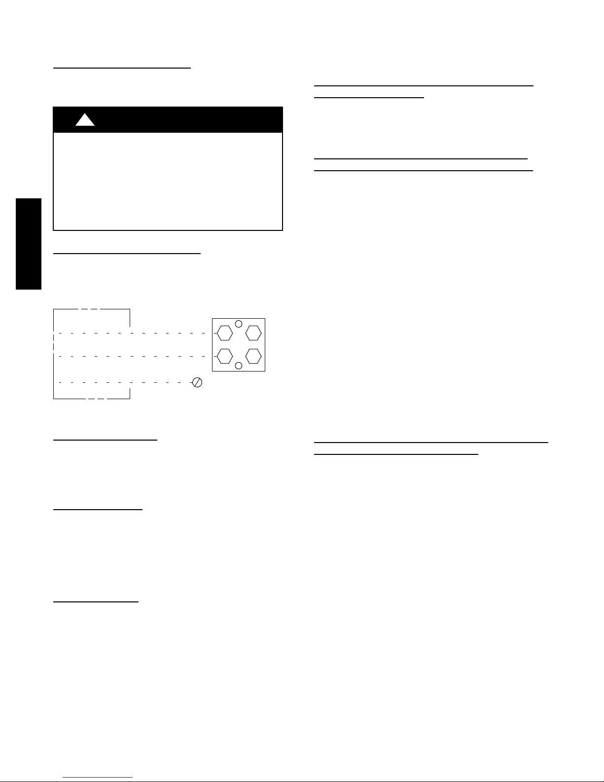
safety. Connect power wiring to contactor as shown in Fig. 5.
DISCONNECT
PER N. E. C. AND/OR
LOCAL CODES
CONTACTOR
FIELD POWER
WIRING
FIELD GROUND
WIRING
Fig. 5 -- Line Power Connections
GROUND
LUG
Connect Control Wiring
Route low voltage control wires through control wiring grommet
and connect leads to control board.
For Evolution, connect to ABCD only. For standard
non--communicating thermostats, connect to standard thermostat
connections R, C, W, Y1, Y2, and O.
General Information
Use No. 18 AWG color--coded, insulated (35°C minimum) wire for
all installations.
All wiring must be NEC Class 1 and must be separated from
incoming power leads.
Use furnace transformer, fan coil transformer, or accessory
transformer for control power, 24v/40va minimum. The outdoor
unit requires a minimum of 27va/24vac control power.
Final Wiring Check
IMPORTANT: Check factory wiring and field wire connections
to ensure terminations are secured properly. Check wire routing to
ensure wires are not in contact with tubing, sheet metal, etc.
CompressorCrankcaseHeater
Furnish power to crankcase heater a minimum of 24 hr before
starting unit. To furnish power to heater only, set thermostat to
OFF and close electrical disconnect to outdoor unit.
NOTE: On 286A models, starting the compressor without a
minimum of 12 hours of crankcase heat prior to initial start--up
may result in a compressor chattering noise and possible damage to
the compressor.
A91056
Install Accessories
Refer to the individual instructions packaged with kits or
accessories when installing.
Make Airflow Selections
Airflow Setup for Evolution Control Furnace of FE
Fan coil
When using an Evolution User Interface, airflow is
automatically selected based on equipment size. See User
Interface Installation Instructions for available
adjustments.
Airflow Selection for Variable Speed Furnaces
Non--Communicating (non--Evolution)
The variable speed furnaces provide blower operation to match the
capacities of the compressor during high and low stage cooling
operation, The furnace control board allows the installing
technician to select the proper airflows for each stage of cooling.
Below is a summary of required adjustments. See furnace
installation instructions for more details:
If a higher or lower Continuous Fan speed is desired, the
Continuous Fan speed can be changed using the fan switch on the
thermostat. Refer to the furnace installation instructions for details
of how to use this feature.
Airflow Selection for FV4 Fan Coils for Non--Communicating (Non--Evolution)
The FV4B provides high-- and low--stage blower operation to
match the capacities of 286A compressor at high-- and low-- stage.
The FV4C provides high-- and low-- stage blower operation to
match the capacities of 288A compressor at high-- and low--stage
(units containing circuit board HK38EA015 or newer). To select
recommended airflow, refer to FV4 Installation Instructions. The
FV4 utilizes an Easy Select control board that allows the installing
technician to select proper airflows. For adjustments to control
board, select appropriate HP SIZE and CFM ADJUST setting. This
fan coil has an adjustable blower off delay factory set at 90 sec for
high-- and low--stage blower operation.
(communicating)
for
Thermostats
1. Turn SW1 --5 ON for 400 CFM/ton airflow or OFF for 350
CFM/ton airflow. Factory default is OFF.
2. The A/C DIP switch setting determines airflow during high
stage cooling operation. Select the A/C DIP switch setting
corresponding to the available airflow shown in the furnace
installation instructions that most closely matches the required airflow shown in the air conditioning Product Data
for HIGH speed.
3. The CF DIP switch setting determines airflow during low
stage cooling operation. Select the CF DIP switch setting
corresponding to the available airflow shown in the furnace
installation instructions that most closely matches the required airflow shown in the air conditioning Product Data
for LOW speed.
Thermostats
6
Page 7
Start--Up
!
UNIT OPERATION AND SAFETY HAZARD
Failure to follow this caution may result in minor personal
injury, equipment damage or improper operation.
Observe the following:
1. Do not overcharge system with refrigerant.
2. Do not operate unit in a vacuum or at negative pressure.
3. Do not disable low pressure switch
4. Dome temperatures may be hot.
!
PERSONAL INJURY HAZARD
Failure to follow this caution may result in personal injury.
Wear safety glasses, protective clothing, and gloves when
handling refrigerant.
!
ENVIRONMENTAL HAZARD
Failure to follow this caution may result in environmental
damage.
Federal regulations require that you do not vent
refrigerant to the atmosphere. Recover during system
repair or final unit disposal.
Follow these steps to properly start up the system:
1. After system is evacuated, fully back seat (open) liquid and
vapor service valves.
2. Unit is shipped with valve stem(s) front seated (closed) and
caps installed. Replace stem caps after system is opened to
refrigerant flow (back seated). Replace caps finger--tight and
tighten with wrench an additional 1/12 turn.
3. Close electrical disconnects to energize system.
4. Set room thermostat or User Interface at desired temperature. Be sure set point is below indoor ambient temperature
and is set low enough to energize desired stage.
5. Set room thermostat or User Interface to COOL and fan
control to ON or AUTO mode, as desired. Operate unit for
15 minutes. Check system refrigerant charge.
NOTE: Non--communicating (non--Evolution) Bryant thermostats
are equipped with a 15--minute staging timer. This timer prevents
the two--stage system from operating at high stage until unit has
been operating in low stage for 15 minutes, unless there is at least a
±5°F(±2.8°C) difference between room temperature and thermostat
set point. To force high stage (after a minimum of 2 minutes in low
stage), adjust the set point at least ±5°F(±2.8°C) below room
ambient.
6. Set room thermostat or User Interface to HEAT or COOL
and fan control to AUTO or ON, as desired. Wait for appropriate time delay(s). Operate unit for 15 minutes. Check refrigerant charge.
CAUTION
CAUTION
CAUTION
System Functions and Sequence of Operation
The outdoor unit control system has special functions. The
following is an overview of the two--stage control functions:
Cooling and Heating Operation
The 286A and 288A (containing circuit board HK38EA015 or
newer) models utilize either a standard indoor thermostat or
Evolution Communication User Interface. With a call for first
stage cooling, the outdoor fan, reversing valve, and low stage
compressor are energized. If low--stage cannot satisfy cooling
demand, high-- stage cooling is energized by the second stage of
indoor thermostat or User Interface. After second stage is satisfied,
the unit returns to low--stage operation until first stage is satisfied
or until second stage is required again. When both first stage and
second stage cooling are satisfied, the compressor will shut off. The
reversing valve will remain energized until the control board power
is removed or a call for heating in initiated. With a call for heating,
the outdoor fan and compressor are energized. The compressor will
operate in high or low stage operation, as needed to meet the
heating demand. When the heating demand is satisfied, the
compressor and fan will shut off. The reversing valve is
de--energized in the heating mode.
NOTE: When two--stage unit is operating at low--stage, system
vapor (suction) pressure will be higher than a standard single--stage
system or high--stage operation.
NOTE: Outdoor fan motor will continue to operate for one
minute after compressor shuts off, when outdoor ambient is greater
than or equal to 100°F. This reduces pressure differential for easier
starting on next cycle.
NOTE: On 286A models, if unit has not operated within the past
12 hours, or following a unit power-- up, upon the next thermostat
high-- or low--stage demand, unit operates for a minimum of 5
minutes in high--stage.
With non--communicating (non--Evolution) systems, with first
stage of cooling, Y1 and O are powered on; and with second stage
of cooling, Y1, Y2, and O are on. For these systems, with first
stage of heating Y1 is on and for second stage of heating, Y1 and
Y2 are on. When the reversing valve is energized, O is powered
on.
Communication and Status Function Lights
For Evolution Control only, Green communications (COMM)
Light
A green LED (COMM light) on the outdoor board (see Fig. 6)
indicates successful communication with the other system
products. The green LED will remain OFF until communication is
established. Once a valid command is received, the green LED will
turn ON continuously. If no communication is received within 2
minutes, the LED will be turned OFF until the next valid
communication.
Amber Status Light
An amber colored STATUS light is used to display the operation
mode and fault codes as specified in the troubleshooting section.
See Table 6 for codes and definitions.
NOTE: Only one code will be displayed on the outdoor unit
control board (the most recent, with the highest priority).
Utility Interface
With Evolution Control
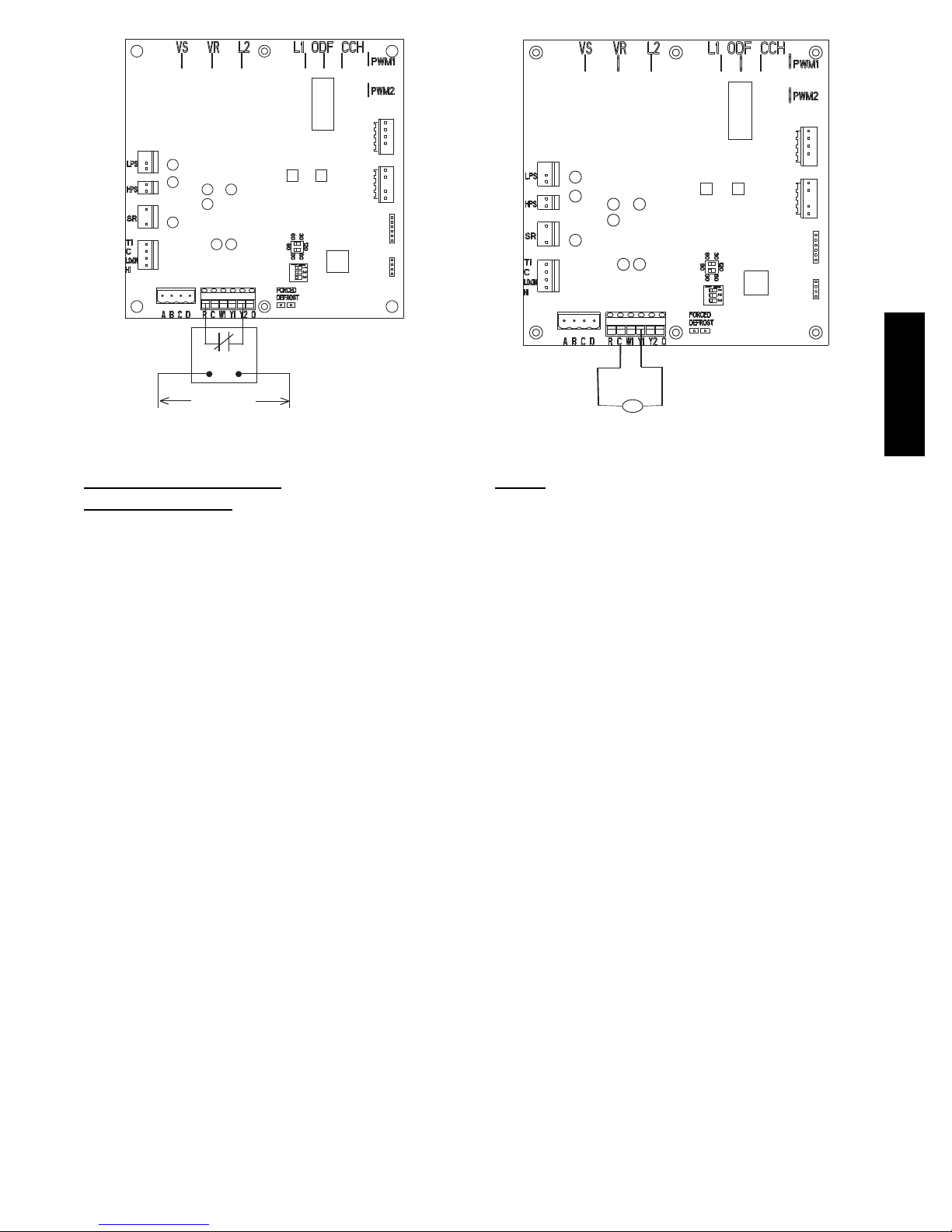
The utility curtailment relay should be wired between R and Y2
connections on the control board for Evolution Communicating
Systems only (see Fig. 6.) This input allows a power utility device
to interrupt compressor operation during peak load periods. When
the utility sends a signal to shut the system down, the User
Interface will display, “Curtailment Active”.
286A / 288A
7
Page 8
One Minute Stage Change Time Delay on 286A Models
When compressor changes stages from high to low or low to high,
there is a 1--minute time delay before compressor restarts. The
outdoor fan motor remains running.
Compressor Operation on 286A Models
When the compressor operates in high stage operation, the
compressor motor rotates clockwise. Both the lower and upper
pistons are eccentric with the rotating crankshaft and both
compress refrigerant.
When the compressor operates in low stage operation, the
compressor motor reverses direction (rotates counterclockwise).
The lower piston becomes idle and the upper piston compresses
refrigerant. The start and run windings are reversed.
Crankcase Heater Operation
The crankcase heater is energized during unit off cycle regardless
of outside air temperature (OAT) on 286A models.
The crankcase heater is energized during off cycle below 65°F
(18.33°C) on 288A models.
Outdoor Fan Motor Operation
The outdoor unit control energizes outdoor fan anytime
compressor is operating, except for defrost or low--ambient
286A / 288A
cooling. The outdoor fan remains energized if a pressure switch or
compressor overload should open. Outdoor fan motor will
continue to operate for one minute after the compressor shuts off
when the outdoor ambient is greater than or equal to 100°F
(37.78°C). This reduces pressure differential for easier starting on
next cycle. On 286A models, the outdoor fan remains energized
during the 1 --minute compressor staging time delay.
On 286A models, the outdoor fan motor is a PSC type. A fan relay
on the control board turns the fan off and on by opening and
closing a high voltage circuit to the motor. It does not change
speeds between low and high stage operation.
On 288A models, the outdoor fan is an ECM type. The motor
control is continuously powered with high voltage. The motor
speed is determined by electrical pulses provided by the PWM
outputs on the control board. The ECM motor RPM adjusts to
outdoor conditions as described in Table 3. The PWM output can
be measured between the PWM1 and PWM2 terminals on the
circuit board with a volt meter set to DC volts.
In low ambient cooling (below 55_F/12.78_C) on 286A and 288A
models, the control board cycles the fan off and on.
Table 3 – Outdoor Fan Motor PWM
Outdoor Temp (DC volts, Tolerance +/-- 2%)
Model
288A024 8.72 9.35 11.9
288A036 9.06 10.23 11.9
288A048 9.91 11.04 11.9
288A060 10.83 11.7 11.9
NOTE: For 288A models in low ---ambient cooling, the PWM output for
b o t h h i g h --- a n d l o w --- s t a g e e q u a l s t h e v a l u e f o r l o w --- s t a g e o p e r a --tion below 55_F (12.8_C).
Low Stage
(OAT≤104_F/40_C)
High Stage
(OAT≤104_F/40_C)
Low & High
(OAT>104_F/40_C)
Stage
Time Delays
The unit time delays include:
S F ive m in u te time delay to start coo lin g o r heating operatio n
when there is a call fro m th e therm o stat or user interface. To
bypass this feature, momentarily short and release Forced
Defrost pins.
S Five minute compressor re--cycle delay on return from a
brown--out condition.
S Two minute time delay to return to standby operation from
last v alid co mm u nication (with E v o lu tio n only).
S One minute time delay of outdoor fan at termination of
cooling mode when outdoor ambient is greater than or equal
to 100_F (37.78_C).
S Fifteen second delay at termination of defrost before the
auxiliary heat (W1 ) is de -- energized .
S Twenty second delay at termination of defrost before the
outdoor fan is energized (unless fan delay defeated).
S T hirty second compresso r delay w h en quiet shift enabled.
S On 286A models there is a 1 minute time delay between
staging from lo w to h ig h and from high to lo w cap acity. On
288A models there is no delay; the compressor will change
from low to high and from high to low capacity “on the fly”
to meet the demand .
Compressor Operation on 288A Models:
The basic scroll design has been modified with the addition of an
internal unloading mechanism that opens a by--pass port in the first
compression pocket, effectively reducing the displacement of the
scroll. The opening and closing of the by--pass port is controlled
by an internal electrically operated solenoid. The modulated scroll
uses a single step of unloading to go from full capacity to
approximately 67% capacity.
A single speed, high efficiency motor continues to run while the
scroll modulates between the two capacity steps. Modulation is
achieved by venting a portion of the gas in the first suction pocket
back to the low side of the compressor, thereby reducing the
effective displacement of the compressor.
Full capacity is achieved by blocking these vents, thus increasing
the displacement to 100%. A DC solenoid in the compressor
controlled by a rectified 24 volt AC signal in the external solenoid
plug moves the slider ring that covers and uncovers these vents.
The vent covers are arranged in such a manner that the compressor
operates at approximately 67% capacity when the solenoid is not
energized and 100% capacity when the solenoid is energized. The
loading and unloading of the two step scroll is done ”on the fly”
without shutting off the motor between steps.
NOTE: 67% compressor capacity translates to approximately
75% cooling or heating capacity at the indoor coil.
The compressor will always start unloaded and stay unloaded for
five seconds even when the thermostat is calling for high stage
capacity.
8
Page 9
MODEL
PLUG
UTILITY RELAY *
UTILITY SIGNAL
OPEN RELAY
* SUPPLIED BY UTILITY PROVIDER
A06525
Fig. 6 -- 2-- Stage Control Board
GENERAL INFORMATION
Low Ambient
When this unit is operating below 55_F (12.78_C) outdoor
temperature, provisions must be made for low ambient operation.
Evolution Controlled low ambient cooling:
This unit is capable of low ambient cooling without a kit ONLY
when using Evolution control. A low ambient kit is not required,
and the outdoor fan motor does not need to be replaced for
Evolution controlled low ambient operation. The Evolution
Control provides an automatic evaporator coil freeze protection
algorithm th at eliminates the need for an evapo rator freeze
thermostat. Low ambient cooling must be enabled in the User
Interface set up. Fan may not begin to cycle until about 40_F
(4.4 _C) OAT. Fan will cycle based on coil and outdoor air
temperature.
Evolution controlled low ambient mode operates as follows:
S Fan isOFF when outdoor coil tempis < (outdoor air temperature
+3_F/1.7_C) or outdoor fan has been ON for 30 minutes. (Fan
is tu rn ed o ff to allow refrigeran t system to stab ilize.)
S Fan is ON when outdoor coil temp > (outdoor air temperature +
25_F / 13.9_C) or outdoor coil temp > 80_F/26.7_Corif
outdoor fan has been OFF for 30 minutes. (Fan is turned on to
allow refrigerant system to stab ilize.)
S Low pressure switch is ignored for first 3 minutes during low
ambient start up. After 3 minutes, if LPS trips,then outdoorfan
motoris turned off for 10 minutes, with the compressorrunning.
If LPS closes within 10 min u tes then co o lin g co n tin u es w ith th e
outdoorfan cyclingper the coil temperature routine listedabove
for the remainder of the cooling cycle. If the LPS does not close
within 10 minutes, then the normal LPS trip response (shut
down cooling operationand generate LPS trip error) will occur.
For 288A models, the PWM output for both high and low stage
equals the value for low stage operation below 55_F (12.8_C).
Cooling
MODEL
PLUG
LLS
Liquid Line Solenoid
A06526
Defrost
This control offers 5 possible defrost interval times: 30, 60, 90, 120
minutes, or AUTO.
These are selected by dip switches on the unit control board or by
the Evolution Control User Interface. The Evolution Control
selection overrides the control board dip switch settings.
AUTO defrost adjusts the defrost interval time based on the last
defrost time as follows:
S When defrost time <3 minutes, the next defrost interval=120
minutes.
S When defrost time 3--5 minutes, the next defrost interval=90
minutes.
S When defrost time 5--7 minutes, the next defrost interval=60
minutes.
S When defrost time >7 minutes, the next defrost interval=30
minutes.
The control board accumulates compressor run time. As the
accumulated run time approaches the selected defrost interval time,
the control board monitors the coil temperature sensor for a defrost
demand. If a defrost demand exists, a defrost cycle will be initiated
at the end of the selected time interval. A defrost demand exists
when the coil temperature is at or below 32_F(0_C) for 4 minutes
during the interval.
The defrost cycle is terminated when the coil temperature reaches
65_F (18.33_C)or 10 minutes has passed.
On 286A models, defrost will occur in low-- or high--stage as
demanded by the thermostat or User Interface regardless of OAT
On 288A models, when OAT is >25_F(--3.9_C), defrost will occur
in low-- or high--stage as demanded by the thermostat or User
Interface.
On 288A models, if OAT is ≤25_F(--3.9_C), defrost will occur in
high--stage only, regardless of thermostat or User Interface demand,
and will terminate at 50_F(10_C) coil temperature with a
minimum of 2.5 minutes in defrost.
If the coil temperature does not reach 32_F(0_C) within the
interval, the interval timer will be reset and start over.
S U p on initial pow er up th e first defrost interv al is defaulted t o
30 minu tes. Rem ain i n g in terv als are at selected times.
S Defrost is only allowed to occur below 50_F(10_C)outdoor
ambient temp erature.
286A / 288A
9
Page 10
The outdoor fan output (ODF) will remain off for 20 seconds after
termination. This delay will allow time for the system to capture
the heat from the outdoor coil and reduce the “steam cloud” effect
that may occur on transition from defrost to the heating cycle. The
outdoor fan output OFF delay of 20 seconds may be defeated to
enable the fan to energize immediately at the time of termination
and 12 seconds prior to the reversing valve de-- energizing, through
the User Interface setup screen available with SYSTXBBUID01--C
UI, or forced defrost pins as follows:
S The ODF fan delay defeat can be toggled by shorting the
forced defrost pins for >15 seconds while in the standby
mode (status LE D on solid). The L E D w ill start to flash when
the toggle has taken place.
S Status code 4 shows the fan delay defeat is active (no delay)
S Status code 3 shows that it is not active (20 second delay)
The code will continue to be displayed until after the short is
removed. Once the short is removed, there is a 5 second wait
before the code is cancelled. The code that is flashing will finish
before going back to sold LED. the control is shipped with the
ODF fan delay defeat NOT active. the change in status is
remembered until toggled to a new status. A power down / power
up sequence will not reset the status. It may be necessary to do the
toggle twice to cycle to the desired state of defeat.
286A / 288A
Defrost Hold
In a non--communicating system, if the thermostat becomes
satisfied (Y1 or Y1 and Y2) before the defrost cycle is terminated,
the control will “hold” in defrost mode and finish the defrost cycle
on the next call for heat.
On 286A and 288A models, with communicating Evolution
Control, defrost hold is not needed in a communicating system
because the User Interface will complete the defrost cycle before
shutting down the system.
Forced Defrost
With non --communicating (non--Evolution) control, forced defrost
can be initiated by manually shorting the 2--pin header labeled
FORCED DEFROST (see Fig 6) on the control board for 5
seconds then releasing.
On 286A and 288A with communicating (Evolution) control,
forced defrost is initiated with the User Interface.
On all models, during a Forced Defrost:
S If coil temp erature is at defro st temp eratu re of 32_F(0_C),
and outdoor air temperature is below 50_F(10_C), a full
defrost sequence will occur.
S If coil temperature or outdoor air temperature does not meet
the above requirements, an abbreviated 30 second defrost will
occur.
Quiet Shift
Quiet Shift is a field-- selectable defrost mode which may eliminate
occasional noise that could be heard at the start of the defrost cycle
and restarting of the heating cycle. With a non--communicating
system, this feature must be enabled by selecting the 3rd position
of the 3--position dip switch. For 286A and 288A models with
communicating (Evolution) systems, it must be enabled at the User
Interface. When activated, the following sequence of operation
will occur. Reversing valve will energize and compressor will turn
off for 30 seconds, then turn back on to complete defrost. At the
end of the defrost cycle, the reversing valve de--energizes,
compressor will turn off for another 30 seconds, and the fan will
turn off for 40 seconds, before starting in the heating mode.
Liquid--Line Solenoid Accessory
In heat pump long--line applications, a liquid--line solenoid is
required to control refrigerant migration in the heating mode. The
solenoid should be installed near the outdoor unit with the arrow
facing the outdoor unit. This is the direction of flow control. See
application manual for long-- line application details.
Accessory Liquid Solenoid with Evolution Communicating
Control: When using the Evolution Control, the liquid--line
solenoid output is provided at the Y1 connection. Connect the
solenoid as shown in the wiring label diagram. This is a 24vac
output that is energized whenever the compressor is energized. It
closes, in the compressor off mode, to prevent refrigerant migration
into the unit through the liquid--line.
On Models with Accessory Liquid Solenoid Using a
Non--Communicating Thermostat: The liquid solenoid is
connect to the Y1 and C terminal connections. The liquid solenoid
closes, in the compressor off mode, to prevent refrigerant migration
into the unit through the liquid--line.
Check Charge
All 286A units must be charged in high stage only.
Factory charge amount and desired subcooling are shown on unit
rating plate. Charging method is shown on information plate inside
unit. To properly check or adjust charge, conditions must be
favorable for subcooling charging. Favorable conditions exist
when the outdoor temperature is between 70_F and 100_F
(21.11_C and 37.78_C), and the indoor temperature is between
70_F and 80_F (21.11_C and 26.67_C). Follow the procedure
below:
Unit is factory charged for 15ft (4.57 m) of lineset. Adjust charge
by adding or removing 0.6 oz/ft of 3/8 liquid line above or below
15ft (4.57 m) respectively.
For standard refrigerant line lengths (80 ft/24.38 m or less), allow
system to operate in cooling mode at least 15 minutes. If conditions
are favorable, check system charge by subcooling method. If any
adjustment is necessary, adjust charge slowly and allow system to
operate for 15 minutes to stabilize before declaring a properly
charged system.
If the indoor temperature is above 80_F (26.67_C), and the
outdoor temperature is in the favorable range, adjust system charge
by weight based on line length and allow the indoor temperature to
drop to 80_F (26.67_C) before attempting to check system charge
by subcooling method as described above.
If the indoor temperature is below 70_F (21.11_C), or the outdoor
temperature is not in the favorable range, adjust charge for line set
length above or below 15ft (4.57 m) only. Charge level should then
be appropriate for the system to achieve rated capacity. The charge
level could then be checked at another time when the both indoor
and outdoor temperatures are in a more favorable range.
NOTE: If line length is beyond 80 ft (24.38 m) or greater than 20
ft (6.10 m) vertical separation, See Long Line Guideline for
special charging requirements.
Heating Check Chart Procedure
To check system operation during heating cycle, refer to the Heat
Pump Charging Instructions label on outdoor unit. This chart
indicates whether a correct relationship exists between system
operating pressure and air temperature entering indoor and outdoor
units. If pressure and temperature do not match on chart, system
refrigerant charge may not be correct. Do not use chart to adjust
refrigerant charge.
NOTE: In heating mode, check refrigerant charge only when
pressures are stable. If in doubt, remove charge and weigh in
correct refrigerant charge.
NOTE: When charging is necessary during heating season, charge
must be weighed in accordance with unit rating plate, ±0.6 oz./ft.
of 3/8--in. liquid--line above or below 15 ft., respectively.
EXAMPLE:
To calculate additional charge required for a 25--ft. line set:
25 ft. -- 15 ft. = 10 ft. X 0.6 oz./ft. = 6 oz. of additional charge.
10
Page 11
MAJOR COMPONENTS
2--Stage Control Board
The HP control board controls the following functions:
S High and low stage compressor contactor operation
S Outdoor fan motor operation
S Reversing valve operation
S D efro st operation
S L ow ambient coo lin g
S C rankcase heater operatio n
S Compressor external protection
S P ressure sw itch m o n itoring
S Ti me Delays
S On 286A models, high-- and low--stage start relay and
capacitor operation (Bristol compressor only)
Field Connections
On models with non--communicating (non-- Evolution) system, the
two--stage control receives 24vac low-- voltage control system
inputs through the R, C, Y1, Y2 and O connections located at the
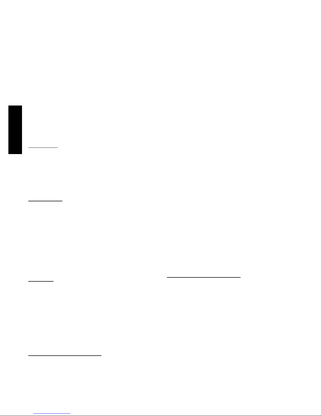
bottom of the control board (see Fig. 6.) On a non--communicating
system, output W1 is connected at the bottom of the control board
for auxiliary heat.
On models with communicating system, use the ABCD Evolution
connections.
Two Stage Compressor
The two stage compressor contains motor windings that provide
2--pole (3500 RPM) operation. For two--stage compressor, refer to
Table 5 for correct winding resistance.
Compressor Internal Relief
The compressor is protected by an internal pressure relief (IPR)
which relieves discharge gas into the compressor shell when
differential between suction and discharge pressure exceeds
500--550 psi on 286A models and 550-- 625 psi on 288A models.
The compressor is also protected by an internal overload attached
to motor windings.
Compressor Control Contactors
The contactor(s) have a 24volt coil. The electronic control board
controls the operation of the appropriate contactor.
TROUBLESHOOTING
Systems Communication Failure
If communication with the Evolution control is lost with the User
Interface, the control will flash the appropriate fault code. (See
Table 6.) Check the wiring to the UI and the indoor and outdoor
units.
Model Plug
Each control board contains a model plug. The correct model plug
must be installed for or the system to operate properly. (See Table
4.)
Table 4 – Model Plug Information
MODEL
NUMBER
286A024 HK70EZ002 5.1 18
286A036 HK70EZ004 5.1 33
286A048 HK70EZ006 5.1 51
286A060 HK70EZ008 5.1 75
288A024 HK70EZ010 5.1 120
288A036 HK70EZ012 5.1 180
288A048 HK70EZ014 5.1 270
288A060 HK70EZ016 11 5.1
MODEL PLUG
NUMBER
The model plug is used to identify the type and size of unit to the
control. On 286A models, the model plug is also used to determine
the start sequence timing for each individual model.
PIN RESISTANCE
( K --- o h m s )
P i n s 1 --- 4 P i n s 2 --- 3
On new units, the model and serial numbers are input into the
board’s memory at the factory. If a model plug is lost or missing at
initial installation, the unit will operate according to the
information input at the factory and the appropriate error code will
flash temporarily. An RCD replacement board contains no model
and serial information. If the factory control board fails, the model
plug must be transferred from the original board to the replacement
board for the unit to operate.
NOTE: The model plug takes priority over factory model
information input at the factory. If the model plug is removed after
initial power up, the unit will operate according to the last valid
model plug installed, and flash the appropriate fault code
temporarily.
Pressure Switch Protection
The outdoor unit is equipped with high-- and low--pressure
switches. If the control senses the opening of a high-- or
low--pressure switch, it will respond as follows:
1. De--energize the appropriate compressor contactor.
2. Keep the outdoor fan operating for 15 minutes.
3. Display the appropriate fault code (see Table 6).
4. After a 15 minute delay, if there is a call for cooling or heating and LPS or HPS is reset, the appropriate compressor
contactor is energized.
5. If LPS or HPS has not closed after a 15 minute delay, the
outdoor fan is turned off. If the open switch closes anytime
after the 15 minute delay, then resume operation with a call
for cooling or heating.
6. If LPS or HPS trips 3 consecutive cycles, the unit operation
is locked out for 4 hours.
7. In the event of a high--pressure switch trip or high--pressure
lockout, check the refrigerant charge, outdoor fan operation,
and outdoor coil (in cooling) for airflow restrictions, or indoor airflow in heating.
8. In the event of a low--pressure switch trip or low--pressure
lockout, check the refrigerant charge and indoor airflow
(cooling) and outdoor fan operation and outdoor coil in
heating.
Control Fault
If the outdoor unit control board has failed, the control will flash
the appropriate fault code (see Table 6). The control board should
be replaced.
Brown--Out Protection
If the line voltage is less than 187v for at least 4 seconds, the
appropriate compressor contactor and fan relay are de--energized.
Compressor and fan operation are not allowed until voltage is a
minimum of 190v. The control will flash the appropriate fault code
(see Table 6).
230v Brown--Out P rotec t ion Defeated
The brownout feature can be defeated if needed for severe noisy
power conditions. This defeat should always be a last resort to
solving the problem. Defeat is available on the User Interface
setup screen (available with SYSTXBBUID01--C UI) or can be
initiated through the forced defrost pins for non-- communicating
systems as follows:
The brownout toggle is accomplished by shorting the defrost pins
from power up with the OAT and OCT sensor connector removed.
After 3 seconds, the status of the force defrost short and the
OAT/OCT as open will be checked. If correct, then the brownout
will be toggled.
S Status code 6 shows the brownout is disabled.
S Status code 5 shows the brownout is active.
After the brownout defeat is set, power down and reinstall the
OAT/OCT sensor and remove the short from the forced defrost
pins. As long as the short on the forced defrost remains, the OAT
286A / 288A
11
Page 12
and OCT faults will not be cleared. The code will continue to be
flashed.
The control is shipped with the brownout active. The change in
status is remembered until toggled to a new status. A power
down/power up sequence will not reset the status. It may be
necessary to do the toggle twice to cycle to the desired state of the
defeat.
230V Line (Power Disconnect) Detection
If there is no 230v at the compressor contactor(s) when the indoor
unit is powered and cooling or heating demand exists, the
appropriate fault code is displayed. Verify the disconnect is closed
and 230v wiring is connected to the unit.
Compressor Voltage Sensing
The control board input terminals labeled VS, VR and L2 on 286A
models and VS and L2 on 288A models (see Fig. 6) are used to
detect compressor voltage status and alert the user of potential
problems. The control continuously monitors the high voltage on
the run capacitor of the compressor motor. Voltage should be
present any time the compressor contactor is energized and voltage
should not be present when the contactor is de--energized.
Contactor Shorted Detection
If there is compressor voltage sensed when there is no demand for
286A / 288A
compressor operation, the contactor may be stuck closed or there
may be a wiring error. The control will flash the appropriate fault
code.
286A Models -- Compressor Thermal Cutout
The control senses the compressor voltage at VR and VS. When
starting or running, a phase difference of the voltages on the inputs
will indicate the thermal protector is closed. If the phase difference
is 5_ or less for 10 seconds, the internal protector is open. The
control de--energizes the appropriate compressor contactor for 15
minutes, but continues to operate the outdoor fan. The control
Status LED will flash the appropriate code shown in Table 6. After
15 minutes, with a call for low or high stage cooling or heating, the
appropriate compressor contactor is energized. If the thermal
protector has not re--set, the outdoor fan is turned off. If the call for
cooling or heating continues, the control will energize the
compressor contactor every 15 minutes. If the thermal protector
closes, (at the next 15 minute interval check) the unit will resume
operation.
If the thermal cutout trips for three consecutive cycles, then unit
operation is locked out for 4 hours and the appropriate fault code is
displayed.
288A Compressor Thermal Cutout
If the control senses the compressor voltage after start--up and is
then absent for 10 consecutive seconds while cooling or heating
demand exists, the thermal protector is open. The control
de--energizes the compressor contactor for 15 minutes, but
continues to operate the outdoor fan. The control Status LED will
flash the appropriate code shown in Table 6. After 15 minutes,
with a call for low or high stage cooling or heating, the compressor
contactor is energized. If the thermal protector has not re--set, the
outdoor fan is turned off. If the call for cooling or heating
continues, the control will energize the compressor contactor every
15 minutes. If the thermal protector closes, (at the next 15 minute
interval check) the unit will resume operation.
If the thermal cutout trips for three consecutive cycles, then unit
operation is locked out for 4 hours and the appropriate fault code is
displayed.
Low or High Contactor Open (286A models) / No 230V
at Compressor Contactor (288A
If the compressor voltage is not sensed when the compressor
should be starting, the appropriate contactor may be stuck open or
there is a wiring error. The control will flash the appropriate fault
code. Check the contactor and control box wiring.
models)
286A Models Only -- Compressor Start Detection on
Models with Bristol Compressors
In low stage, if the specified start voltage at VR terminal is not
achieved, the start relay is de--energized after 1 second and the
control will flash the appropriate fault code.
In high stage, if the specified start voltage at VS terminal is not
achieved, the start relay is de--energized after 1 second and the
control will flash the appropriate fault code.
If the specified start voltage is not achieved for 3 consecutive low
stage starts, low stage operation is locked out for 30 minutes. If the
specified start voltage is not achieved for 3 consecutive high stage
starts, high stage operation is locked out for 30 minutes. The
control will flash the appropriate fault code.
Only
Troubleshooting 286A units for proper switching
between low & high
Check the suction and liquid pressures at the service valves.
Suction pressure should be reduced by 5--10% when switching
from low to high capacity. There should be a 10--20% increase in
liquid pressure when switching from low to high capacity.
Compressor current should increase 100--250% when switching
from low to high stage.
stages
Troubleshooting 288A units for proper switching
between low & high
Check the suction pressures at the service valves. Suction pressure
should be reduced by 3--10% when switching from low to high
capacity.
NOTE: The liquid pressures are very similar between low and
high stage operation, so liquid pressure should not be used for
troubleshooting.
Compressor current should increase 20-- 45% when switching from
low to high stage. The compressor solenoid when energized in
high stage, should measure 24vac.
When the compressor is operating in low stage the 24v DC
compressor solenoid coil is de--energized. When the compressor is
operating in high stage, the 24v DC solenoid coil is energized. The
solenoid plug harness that is connected to the compressor HAS an
internal rectifier that converts the 24v AC signal to 24v DC. DO
NOT INSTALL A PLUG WITHOUT AN INTERNAL
RECTIFIER.
stages
Unloader Test Procedure
The unloader is the compressor internal mechanism, controlled by
the DC solenoid, that modulates between high and low stage. If it
is suspected that the unloader is not working, the following
methods may be used to verify operation.
1. Operate the system and measure compressor amperage.
Cycle the unloader on and off at 30 second plus intervals at
the UI (from low to high stage and back to low stage). Wait
5 seconds after staging to high before taking a reading. The
compressor amperage should go up or down at least 20 percent.
2. If the expected result is not achieved, remove the solenoid
plug from the compressor and with the unit running and the
UI calling for high stage, test the voltage output at the plug
with a DC voltmeter. The reading should be 24 volts DC.
3. If the correct DC voltage is at the control circuit molded
plug, measure the compressor unloader coil resistance. The
resistance should be 32 to 60 ohms depending on compressor temperature. If the coil resistance is infinite, much
lower than 32 ohms, or is grounded, the compressor must
be replaced.
Temperature Thermistors
Thermistors are electronic devices which sense temperature. As the
temperature increases, the resistance decreases. Thermistors are
used to sense outdoor air (OAT) and coil temperature (OCT).
Refer to Fig. 7 for resistance values versus temperature.
12
Page 13
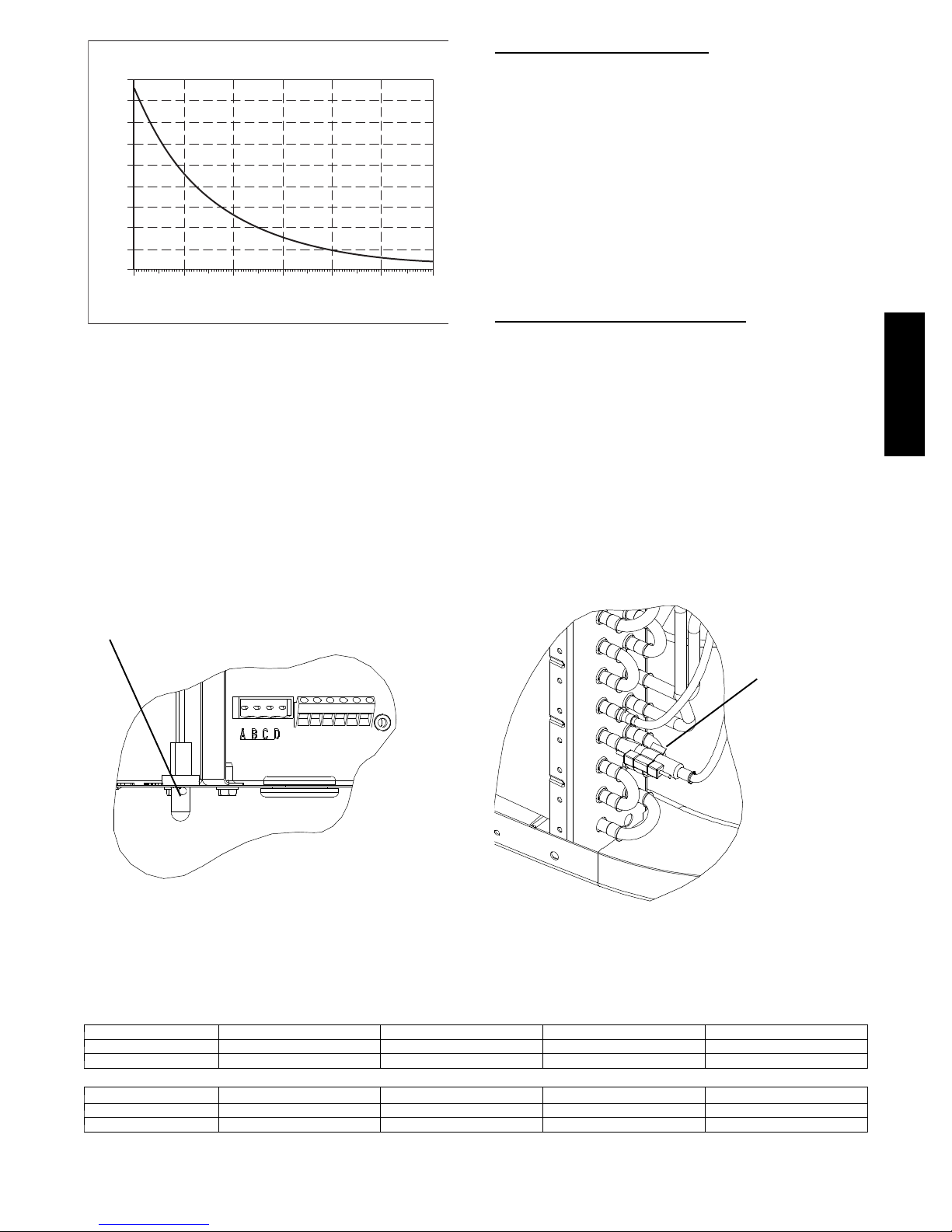
THERMISTOR CURVE
90
80
70
60
50
40
30
20
RESISTANCE (KOHMS)
10
0
0
(-17.77)
If the outdoor air or coil thermistor should fail, the control will
flash the appropriate fault code. (See Table 6.)
IMPORTANT: The outdoor air thermistor and coil thermistor
should be factory mounted in the final locations. Check to ensure
thermistors are mounted properly per Fig. 8 and Fig. 9.
20
(-6.67)
40
(4.44)
TEMPERATURE °F (°C)
60
(15.56)
(26.67)
80
100
(37.78)
Fig. 7 -- Resistance Values Versus Temperature
120
(48.89)
A08054
Thermistor Sensor Comparison
The control continuously monitors and compares the outdoor air
temperature sensor and outdoor coil temperature sensor to ensure
proper operating conditions. The comparison is:
S In cooling if the outdoor air sensor indicates ≥ 10_F
(≥ 5.6_C) warmer than the coil sensor (or) the outdoor air
sensor indicates ≥ 20_F(≥ 11_C) cooler than the coi l senso r,
the sensors are out of range.
S In heating if the outdoor air sensor indicates ≥ 35_F(≥
19.4_C) warmer than the coil sensor (or) the outdoor air
sensor indicates ≥ 10_F(≥ 5.6_C) coo ler than th e coi l senso r,
the sensors are out of range.
If the sensors are out of range, the control will flash the appropriate
fault code as shown in Table 6.
The thermistor comparison is not performed during low ambient
cooling or defrost operation.
Failed Thermistor Default Operation
Factory defaults have been provided in the event of failure of
outdoor air thermistor (OAT) and/or outdoor coil thermistor
(OCT).
If the OAT sensor should fail, low ambient cooling will not be
allowed and the one--minute outdoor fan off delay will not occur.
Defrost will be initiated based on coil temperature and time.
If the OCT sensor should fail, low ambient cooling will not be
allowed. Defrost will occur at each time interval during heating
operation, but will terminate after 5 minutes.
If there is a thermistor out of range error, defrost will occur at each
time interval during heating operation, but will terminate after 5
minutes.
Count the number of short and long flashes to determine the
appropriate flash code. Table 6 gives possible causes and actions
related to each error.
286A / 288A
OAT Thermistor must be locked in
place with spherical nib end facing towards the front of the control box
Fig. 8 -- Outdoor Air Thermistor (OAT) Attachment
Fig. 9 -- Outdoor Coil Thermistor (OCT) Attachment
Table 5 – Two--Stage Compressor Resistances
(Winding Resistance at 70_F±20_F/21_C±11_C)
Winding 286A024 286A036 286A048 286A060
Start (S--C) 2.74 1.98 1.55 0.74
Run (R--C) 0.80 0.75 0.48 0.36
OCT Thermistor
must be secured
tight on stub tube.
Winding 288A024 288A036 288A048 288A060
Start (S--C) 1.40 1.29 1.52 0.60
Run (R--C) 1.32 0.89 0.64 0.49
13
Page 14
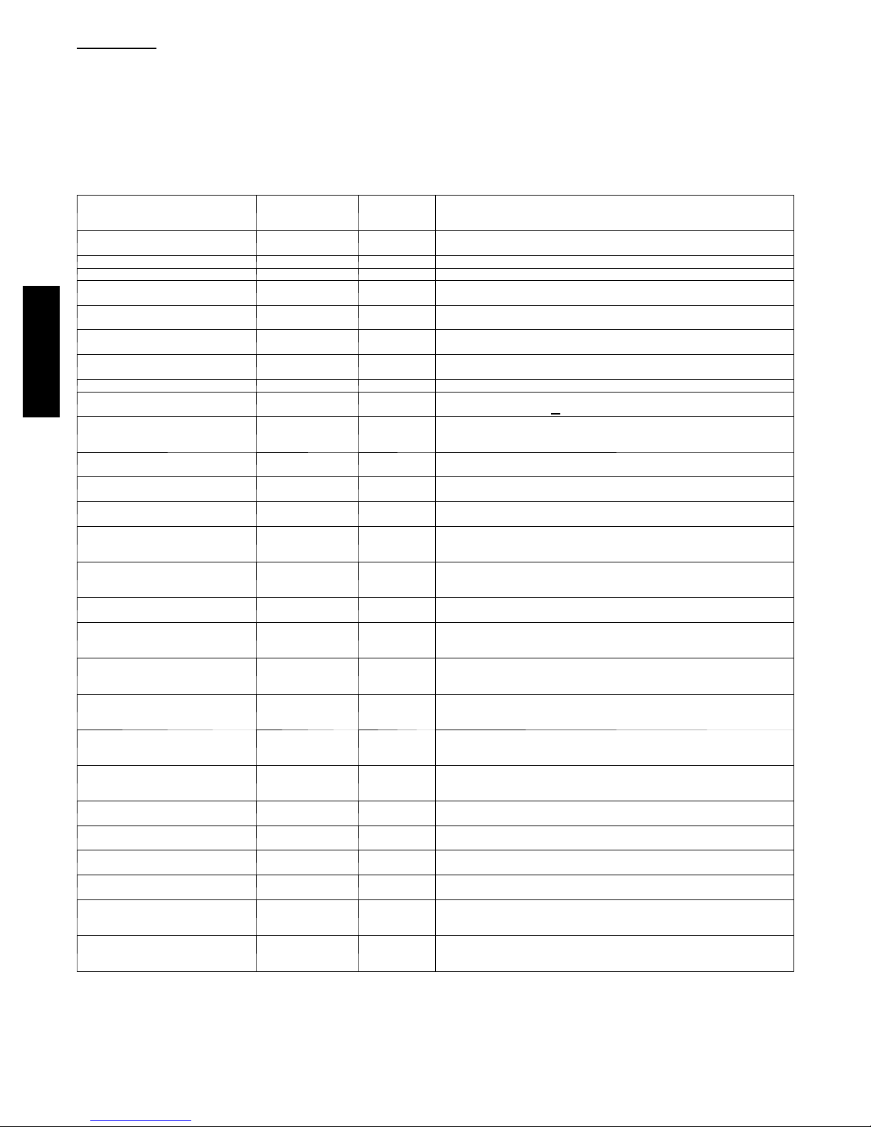
Status Codes
Table 6 shows the status codes flashed by the amber status light.
Most system problems can be diagnosed by reading the status code
as flashed by the amber status light on the control board.
The codes are flashed by a series of short and long flashes of the
status light. The short flashes indicate the first digit in the status
code, followed by long flashes indicating the second digit of the
error code.
Table 6 – TROUBLESHOOTING
AMBER LED
OPERATION
Standby – no call for unit operation None
Low Stage Cool/Heat Operation None 1, pause Normal operation
High Stage Cool /Heat Operation None 2, pause Normal operation
286A / 288A
* Sequence: Compressor contactor is de ---energized and outdoor fan is energized for up to 15 minutes. If demand still exists, control will ener gize compressor
contactor after 15 minute delay. If fault is cleared, unit will resume operation. If fault still exists, fan shuts off, and error code continues to flash. Control will
attempt re ---start every 15 minutes. Cycling low voltage defeats the 15 minute delay.
FAULT
System Communications Failure
Invalid Model Plug 25
High Pressure
Switch Open
Low Pressure
Switch Open
Control Fault 45 Outdoor unit control board has failed. Control board needs to be replaced.
Brown Out (230 v) 46
No 230v at Unit 47
Outdoor Air Temp
Sensor Fault
Outdoor Coil
Sensor Fault
Thermistors out of
range
Low Stage
Thermal Cutout
High Stage
Thermal Cutout
Contactor Shorted 73
No 230V at
Compressor (288A
Only)
Low Stage Did Not
Start
(286A Only)
Low Stage Did Not
Start 3 times (286A
Only)
High Stage Did Not
Start
(286A Only)
High Stage Did Not
Start 3 times (286A
Only)
Low Stage
Thermal Lockout
High Stage
Thermal Lockout
L o w --- P r e s s u r e
Lockout
H i g h --- P r e s s u r e
Lockout
Low Contactor
Open
(286A Only)
High Contactor
Open
(286A Only)
FLASH
CODE
On solid, no
flash
16 Communication with User Interface lost. Check wiring to UI, indoor and
31*
32* Low ---pressure switch trip. Check refrigerant charge and indoor air flow.
53
55 Coil sensor not reading or out of range. Ohm out sensor and check wiring.
56
71*
72*
74
75
76
77
78
81
82
83
84
85
87
The short flash is 0.25 seconds ON and the long flash is 1.0 second
ON. Time between flashes is 0.25 seconds. Time between short
flash and first long flash is 1.0 second. Time between code
repeating is 2.5 seconds with LED OFF.
EXAMPLE:
3 short flashes followed by 2 long flashes indicates a 32 code.
Table 6 shows this to be low pressure switch open.
POSSIBLE CAUSE AND ACTION
Normal operation
outdoor units
Control does not detect a model plug or detects an invalid model plug. Unit
will not operate without correct model plug.
High---pressure switch trip. Check refrigerant charge, outdoor fan operation
and coils for airflow restrictions.
Line voltage < 187v for at least 4 seconds. Compressor and fan operation
not allowed until voltage>
There is no 230v at the contactor when indoor unit is powered and cooling/
heating demand exists. Verify the disconnect is closed and 230v wiring is
connected to the unit.
Outdoor air sensor not reading or out of r ange. Ohm out sensor and check
wiring.
Improper relationship between coil sensor and outdoor air sensor. Ohm ou t
sensors and check wiring.
Compressor operation detected then disappears while low stage demand
exists. Possible causes are internal compressor overload trip or start relay
and capacitor held in circuit too long (if installed).
Compressor operation detected then disappears while high stage demand
exists. Possible causes are internal compressor overload trip or start relay
and capacitor held in circuit too long (if installed).
Compressor voltage sensed when no demand for compressor operation
exists. Contactor may be stuck closed or there is a wiring error.
Compressor voltage not sensed when compressor should be starting. Contactor may be stuck open or there is a wiring error.
Specified start voltage at VR terminal was not achieved in low stage. Start
relay was de ---energized after 1 second.
For 3 consecutive low stage starts, the specified start voltage at VR terminal
was not achieved & start relay was de ---energized. Low stage locked out for
30 minutes.
Specified start voltage at VS terminal was not achieved in high stage. Start
relay was de ---energized after 1 second.
For 3 consecutive high stage starts, the specified start voltage at VS terminal
was not achieved & start relay was de--- energized. High stage locked out for
30 minutes.
Thermal cutout occurs in three consecutive low/high stage cycles. Low
stage locked out for 4 hours or until 24v power recycled.
Thermal cutout occurs in three consecutive high/low stage cycles. High
stage locked out for 4 hours or until 24v power recycled.
Low pressure switch trip has occurred durin g 3 consecutive cycles. Unit
operation locked out for 4 hours or until 24v power recycled.
High pressure switch trip has occurr ed during 3 consecutive cycles. Unit
operation locked out for 4 hours or until 24v power recycled.
Compressor voltage n ot sensed when compressor should be starting. Low
stage contactor may be stuck open or there is a wiring err or.
Compressor voltage not sensed when compressor sh ould be starting. High
stage contactor may be stuck open or there is a wiring err or.
190v. Verify line voltage.
14
Page 15
Outdoor Sensor *
Humidifier Solenoid
Valve *
Remote Room
THERMIDISTAT
W/W1 W/W1 W2 *
Outdoor Sensor *
Humidifier Solenoid
Valve *
Remote Room
RVS/Heat Stage 2 O/B W2
Heat Stage 1 W/W 1
Compressor Low Y1
Compressor High Y/Y2
Fan G
24VAC Hot Heating Rh
24VAC Hot Cooling Rc
Dry Contact 1 D1
Dry Contact 2 D2
24VAC Common C
Humidify HUM
Outdoor Air Temp OAT
Remote Room Sensor RRS
OAT/RRS Com OAT/RRS
FAN
COIL
O
Y1
W1
W2
Y/Y2
G
R
DH
C
2 STAGE
HEAT PUMP
REMOVE J2
JUMPER FOR
HEAT STAGING
REMOVE J1 FOR
DEHUMIDIFY
MODES
W1
Thermidistat
O
Y1
Y2
R
C
RVS Cooling
Heat Stage 3 (furnace)
Heat/Cool Stage 1 Y1 / W2 Y1
Heat/Cool Stage 2 Y/Y2 Y/Y2 Y/Y2
Fan G G
24VAC Hot Heating Rh R R
24VAC Hot Cooling Rc
Dry Contact 1 D1
Dry Contact 2 D2
24VAC Common C COM C
Humidify HUM
Outdoor Air Temp OAT
Remote Room Sensor RRS
OAT/RRS Com SRTN
* Indicates connection may not be required / available.
O/B W2 W2
Variable Speed
Furnace
DHUM
2-Stage
Heat Pump
O
286A / 288A
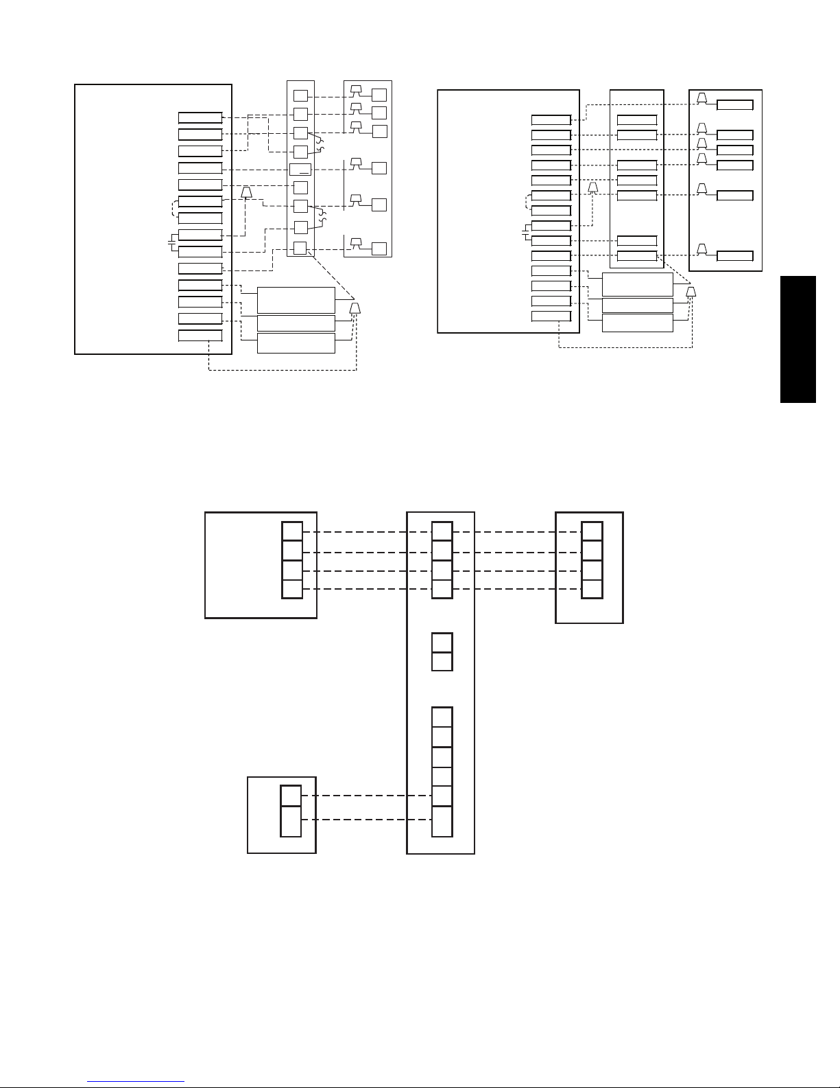
Fig. 10 -- Edge Thermidistat Models T6-- PRH--01 or T6-- NRH--01)
A08055
Wiring with Two--Stage Heat Pump (non--communicating)
User Interface
D
C
B
A
Humidifier
C
F i g . 1 1 -- T h e r m i d i s t a t M o d e l T 6 -- P R H -- 0 1 o r T 6 -- N R H -- 0 1 w i t h
Furnace or Fan Coil
D
C
B
A
OAT
RYOWCHUM
A09337
Variable Speed Furnace and 2-- Stage Heat Pump
(non--communicating)
Communicating HP
D
C
B
A
Fig. 12 -- Evolution Furnace or Fan Coil Wiring with 286A OR 288A Communicating Two--Stage HP
24vac
A08091
15
Page 16
FINAL CHECKS
IMPORTANT: Before leaving job, be sure to do the following:
1. Ensure that all wiring is routed away from tubing and sheet
metal edges to prevent rub--through or wire pinching.
2. Ensure that all wiring and tubing is secure in unit before
adding panels and covers. Securely fasten all panels and
covers.
For continuing high performance and to minimize possible
equipment failure, periodic maintenance must be performed on this
equipment.
Frequency of maintenance may vary depending upon geographic
areas, such as coastal applications. See Owner’s Manual for
information.
CARE AND MAINTENANCE
3. Tighten service valve stem caps to 1/12--turn past finger
tight.
4. Leave Users Manual with owner. Explain system operation
and periodic maintenance requirements outlined in manual.
5. Fill out Dealer Installation Checklist and place in
customer file.
PURONR (R--410A) REFRIGERANT QUICK REFERENCE GUIDE
6. Puron refrigerant operates at 50--70 percent higher pressures than R--22. Be sure that servicing equipment and replacement
components are designed to operate with Puron refrigerant.
7. Puron refrigerant cylinders are rose colored.
8. Recovery cylinder service pressure rating must be 400 psig, DOT 4BA400 or DOT BW400.
9. Puron refrigerant systems should be charged with liquid refrigerant. Use a commercial type metering device in the manifold hose
286A / 288A
when charging into suction line with compressor operating.
10. Manifold sets should be 700 psig high side and 180 psig low side with 550 psig low--side retard.
11. Use hoses with 700 psig service pressure rating.
12. Leak detectors should be designed to detect HFC refrigerant.
13. Puron refrigerant, as with other HFCs, is only compatible with POE oils.
14. Vacuum pumps will not remove moisture from oil.
15. Do not use liquid--line filter driers with rated working pressures less than 600 psig.
16. Do not leave Puron refrigerant suction line filter driers in line longer than 72 hours.
17. Do not install a suction--line filter drier in liquid--line.
18. POE oils absorb moisture rapidly. Do not expose oil to atmosphere.
19. POE oils may cause damage to certain plastics and roofing materials.
20. Wrap all filter driers and service valves with wet cloth when brazing.
21. A factory--approved liquid--line filter drier is required on every unit.
22. Do NOT use an R--22 TXV.
23. If indoor unit is equipped with an R--22 TXV or piston metering device, it must be changed to a hard--shutoff Puron refrigerant
TXV.
24. Never open system to atmosphere while it is under a vacuum.
25. When system must be opened for service, recover refrigerant, evacuate then break vacuum with dry nitrogen and replace filter
driers. Evacuate to 500 microns prior to recharging.
26. Do not vent Puron refrigerant into the atmosphere.
27. Do not use capillary tube coils.
28. Observe all warnings, cautions,andbold text.
29. All indoor coils must be installed with a hard--shutoff Puron refrigerant TXV metering device.
E2009 Bryant Heating & Cooling Systems D 7310 W. Morris St. D Indianapolis, IN 46231 Printed in U.S.A. Edition Date: 07/09
Manufacturer reserves the right to disc ontinue, or change at any time, specifications or designs without notic e and without incurring obligations.
16
Catalog No. II286A--- 0 6
Replaces: II286A---05
 Loading...