

Bryant Evolution SYSTXBB4ZC01 Installation And Start-up Instructions Manual
SYSTXBB4ZC01
Evolutionr Damper Control Module
Installation and Start--Up Instructions
A97038
NOTE: Read the entire instruction manual before starting the
installation.
SAFETY CONSIDERATIONS
Improper installation, adjustment, alteration, service, maintenance,
or use can cause explosion, fire, electrical shock, or other
conditions which may cause death, personal injury or property
damage. Consult a qualified installer, service agency or your
distributor or branch for information or assistance. The qualified
installer or agency must use factory--authorized kits or accessories
when modifying this product. Refer to the individual instructions
packaged with the kits or accessories when installing.
Follow all safety codes. Wear safety glasses, protective clothing,
and work gloves. Have a fire extinguisher available. Read these
instructions thoroughly and follow all warnings and cautions
included in literature and attached to the unit. Consult local
building codes and the current edition of the National Electrical
Code (NEC) NFPA 70. In Canada, refer to the current editions of
the Canadian Electrical Code CSA C22.1.
Recognize safety information. When you see this symbol
the unit and in instructions or manuals, be alert to the potential for
personal injury. Understand the signal words DANGER,
WARNING,andCAUTION. These words are used with the
safety--alert symbol. DANGER identifies the most serious hazards,
which will result in severe personal injury or death. WARNING
signifies hazards, which could result in personal injury or death.
CAUTION is used to identify unsafe practices, which may result
in minor personal injury or product and property damage. NOTE
is used to highlight suggestions which will result in enhanced
installation, reliability, or operation.
on
INSTALLATION CONSIDERATIONS
Before the actual installation of a zoning system can begin,
decisions need to be made to determine the number and location of
zones and sensors. This affects duct and damper selections.
See the Evolutionr System Zoning Design Guide for more
information on specifying and designing zoning systems.
This instruction covers the physical installation and start up of the
Evolutionr Damper Control. Use this instruction to guide the
actual installation process after all the air side decisions have been
made. One Damper Control is capable of handling up to four zones
of operation. When greater than four zones are required, a second
Damper Control Module is needed for zones 5 through 8 (8 zones
maximum).
S Install the Evolutionr Zone Control (Evolutionr Connext Wall
Control) and Remote Room Sensors in non--condensing areas
with ambient temperatures between 32 F and 120 F. In sta ll
dampers and the Evolutionr Damper Control in non --condensing
areas with ambient temperatures between --4 F to 158 F(--20 to
70 C).
S A TXV is required on the indoor coil when used with all
residential split system equipment.
S Proper equipment selection and duct sizing are important in a
zoned system.
S DO NOT USE a bypass damper with the Evolutionr Zoning
System. Additio n of a bypass will cause improper operation.
Airflow management will be performed by the Evolution r
Connext Wall Control algorithms. The Evolutionr Connext
Wall Control will monitor the system and will maintain proper
airflow through the heating / cooling equipment.
INTRODUCTION
The Evolutionr Zoning System allows air conditioning and
heating equipment to control temperatures and humidity in up to 8
distinct spaces, or zones, within a building. Each zone has
independent temperature settings. The comfort temperature
settings can change automatically through the use of schedules.
This allows the Evolutionr System to change temperature settings
in zones to reflect occupancy or usage. For example, the end user
can condition bedrooms in a home from 5:00 PM through 7:00
AM or the kitchen from 3:00 PM through 6:00 PM. The
Evolutionr System uses motorized air volume control dampers
(also called zone dampers) to regulate flow of conditioned air into
zones. In this manner, the system can selectively heat or cool
certain portions of a building depending upon space temperature
requirements.
Each zone requires a motorized zone damper to control the air
supplied to it and a zone sensor to sense temperature in each zone.
There are three types of zone sensors available and may be used in
combination:

S Evolutionr Connext Wall Control (p/n SYSTXCBBECC01,
SYSTXBBECW01, or SYSTXBBECN01) — Each installation
has only one Master wall/zoning control. This is the command
center for the entire system. It will typically be located in Zone 1
to sense and control the temperature in this zone. If desired, a
Remote Room Sensor or a Smart Sensor may be used to sense the
Zone 1 temperature. This can give the installer some flexibility in
locating the Master Evolutionr Connext wall control to another
area.
S Remote Room Sensor (p/n SYSTXBBRRS01) — Any zone may
use a Remote Room Sensor (including Zone 1). This is a
temperature sensor only, having no additional user inputs. In
applications where zone temperature averaging may be desired,
this may be done using 4 Remote Room Sensors in a series /
parallel wiring config u ratio n (S ee Fig . 11 for Remote Room
Sensor Averaging).
S Smart Sensor (p/n SYSTXBBSMS01) — Any zone may use a
Smart Sensor (including Zone 1). It provides a temperature
display and buttons to adjust the desired temperature in that zone
only. It also displays the outdoor temperature and indoor
humidity.
Be sure to select the desired sensor type for each zone. Zone sensors
other than the Evolutionr Connext wall control must be purchased
separately. Installation Instructions for these sensors are included
with them.
INSTALLATION
Step 1 — Check Equipment and Job Site
INSPECT EQUIPMENT—File claim with shipping company,
prior to installation, if shipment is damaged or incomplete.
Step 2 — Component Location and Wiring
Considerations
!
WARNING
ELECTRICAL SHOCK HAZARD
Failure to follow this warning could result in personal injury
or death.
Before installing sensor, turn off all power to unit. There may
be more than one power disconnect.
NOTE: All wiring must comply with national, local, and state
codes.
LOCATING Evolutionr DAMPER CONTROL
All system wiring is run back to the Evolutionr Damper Control.
Select a location near the Evolutionr furnace or fan coil where
wiring from the Evolutionr Connext wall control, each Remote
Room Sensor or Smart Sensor, each damper actuator, and the
equipment itself can come together easily.
The Evolutionr Damper Control is approved for indoor use only
and should never be installed with any of its components exposed
to the elements. The Evolutionr Damper Control (and the zone
dampers) may be installed in any area where the temperature
remains between --4 F to 158 F(--20 Cto70 C), and where
there is no condensation. The cover must be installed to prevent
damage from other sources. Do not locate where it will be
accessible to children. It may be mounted in either vertical or
horizontal position. Remember that wiring access is likely the most
important consideration.
!
CAUTION
ELECTRICAL OPERATION HAZARD
Failure to follow this caution may result in equipment damage
or improper operation.
To prevent possible damage to the Evolutionr Damper
Control, do not mount on plenum, ductwork, or flush against
surface.
LOCATING MASTER ZONING WALL CONTROL
The Evolutionr Connext wall control is the command center for
the Evolutionr Zone System. It should be located where it is easily
accessible and visible to home or business owner. It is also
normally the Zone 1 sensor and as such needs to be located to
properly measure the temperature in Zone 1. If these two
requirements conflict, a separate Remote Room Sensor can be
added for Zone 1.
When a Remote Room Sensor is connected to Zone 1 terminals
(ZS1 and ZS1C) of the Evolutionr Damper Control, the system
automatically switches to using this sensor for Zone 1 and ignores
the sensor within the Evolutionr Connext wall control. This
arrangement allows the Evolutionr Connext wall control to be
located at any convenient place within the home or business. In this
arrangement, only the Zone 1 Remote Room Sensor must be
located in Zone 1.
NOTE: The Evolutionr Connext wall control also controls
humidity functions. If the wall control is not used to control Zone 1
temperature, it must still be located in a suitable area where
humidity control will not be affected.
LOCATING SENSORS
For proper operation, each sensor must accurately measure the
temperature within its zone. For accurate temperature
measurement, the following guidelines should be followed:
Sensor should be mounted:
S Approximately 5 ft. (1.5m) from floor.
S Close to the center of its zone, preferably on an inside wall.
S On a section of wall without pipes or duct work.
Sensor should NOT be mounted:
S Close to a window, on an outside wall, or next to a door leading to
the outside.
S Where it will be exposed to direct light and heat from a lamp, sun,
fireplace, or other temperature radiating object which may cause a
false reading.
S Close to or in direct airflow from supply registers.
S In areas with poor air circulation, such as behind a door or in an
alcove.
WIRING CONSIDERATIONS
Ordinary thermostat wire is ideal when wiring the Evolutionr
Zoning System (shielded cable is not necessary). Use 20 AWG or
larger for typical installations. Lengths over 100 ft. should use 18
AWG or larger wire. Remote Room Sensors require only two
conductors, but it is recommended that at least four conductors be
run. This will allow a Smart Sensor to replace the Remote Room
Sensor with no wiring changes at a later date. The Evolutionr
Connext wall control requires four conductors, each damper
actuator requires three conductors. Cut off or fold back and tape
any unneeded wires. Plan the routing of wiring early to avoid
possible problems later. Remember, all wires converge at the
Evolutionr Damper Control, so its location is important.
2
NOTE: Wiring of the ABCD bus only requires a four-- wire
connection; however, it is good practice to run thermostat cable
having more than four wires in the event of a damaged or broken
wire during installation.
The following color code is recommended for each ABCD bus
connection:
A — Green = Data A
B — Yellow = Data B
C — White = 24 VAC (Com)
D — Red = 24VAC (Hot)
It is not mandatory that the above color code be used, but each bus
connection in the system MUST be wired consistently.
Step 3 — Install Components
INSTALL Evolutionr DAMPER CONTROL
The Evolutionr Damper Control is designed so that wires can enter
it from behind, above, or below. Plan wire routing before mounting
Damper Control.
1. Remove cover to access mounting holes.
2. Mount back plate to wall using screws and wall anchors
provided.
3. Level back plate and tighten screws.
INSTALL MASTER ZONING WALL CONTROL
See the Evolutionr Connext wall control Installation Instructions
for details.
NOTE: Improper wiring of the ABCD connector will cause the
Evolutionr Zoning System to operate improperly. Check to make
sure all wiring is correct before proceeding with installation or
turning on power.
INSTALL REMOTE ROOM SENSORS
1. Separate the sensor cover and mounting back plate by
squeezing the top and bottom of the cover together firmly
by grasping the raised top and bottom ridges. This will release the cover. Mount to the wall using the screws and anchors provided.
2. Pull a 2 --conductor wire through hole on right--hand side.
3. Recommended connection is BLACK to either terminal,
WHITE to remaining terminal (sensor terminals are not
marked for polarity because polarity is not important).
Stranded or common bell wire may be used. Lengths up to
1000 ft. will contribute no noticeable error.
4. Push any extra wire into the wall and seal the hole to prevent air leaks. Align the sensor cover with the base plate,
then press firmly until the cover snaps into place.
INSTALL ZONING SMART SENSOR
See the Evolutionr Zoning Smart Sensor Installation Instructions
for details.
Step 4 — Install Zone Dampers
Proper selection and sizing of dampers is very important for proper
system operation. Be sure to consult the Damper Product Data
Sheet and Evolutionr Zoning Design Guide for assistance in
making these selections. Selection and sizing information is not
provided in this installation instruction. Zone dampers are available
in round, rectangular, and slip--in design, and may be installed in
any position. Install the damper so that the actuator is visible for
inspection and accessible in the event it would need to be serviced.
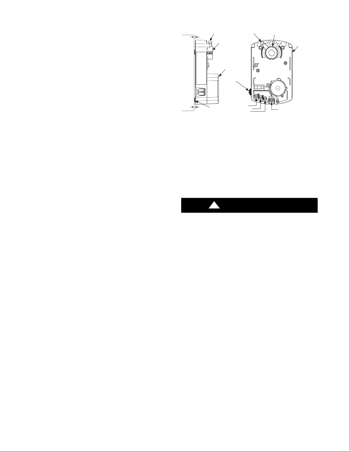
The black mark on the end of the damper shaft represents the
position of the damper blade. To wire the damper, locate the
terminals labeled: OPN (open); COM (common); CLS (closed; and
wire appropriately (see Fig. 1 for Damper 24 VAC connection).
3/16"
GAP
DAMPER
3/16"
GAP
SET SCREW
MOUNTING HUB
ANTI-ROTATION
MOUNTING SCREW
PLASTIC COVER
QUICK BLADE
RELEASE
(CLS) CLOSED
(COM) COMMON
(OPN) OPEN
SET SCREW
CLS
CLS
MOUNTING HUB
ACTUATOR
HOUSING
OPN
COM
COM
OPN
ANTI-ROTATION
MOUNTING SCREW (5/16")
Fig. 1 -- Damper 24VAC Connections
C03024
If the duct system requires multiple dampers for a single zone, up
to five dampers (maximum) may be wired in parallel. For all
applications, including retrofit, it is recommended to use only
current dampers with direct--drive style actuators. DO NOT use
older damper with crank-- arm style actuators.
If an actuator is removed from a damper for any reason, it must be
properly aligned when it is reinstalled. This can be done by
rotating the actuator and the blade to their closed positions and
then tightening the actuator (set screw) to the shaft. This assures
alignment at the closed position. (Pressing the quick blade release
button allows the actuator to be manually turned.)
!
CAUTION
ELECTRICAL OPERATION HAZARD
Failure to follow this caution may result in equipment damage
or improper operation.
Condensation can damage the actuator. When dampers are
located in an unconditioned space, condensation is likely to
occur in cooling. To prevent condensation and losses, all
dampers and ductwork in unconditioned space must be
insulated or otherwise protected.
Whenever condensation might occur, it is recommended that a
plastic actuator cover (p/n, DAMPACTXXCOV) be used over the
actuator. This cover can help prevent condensation on the actuator
by helping to keep out ambient humidity. Insulation may be
applied over the cover to minimize heat transfer.
To install, place the cover over the actuator and seal it in place over
the surrounding insulation with duct tape on all four sides. Sealing
need not be perfect because there will be positive pressure inside
the cover. Do not mount the dampers with their actuators hanging
directly beneath the ductwork. It is best to mount the actuator
facing in either the three or nine o’clock position.
For specific duct types, follow the instructions below:
NOTE: All zone dampers and ductwork must be properly
supported according to local codes or SMACNA standards.
3
 Loading...