

Bryant EVOLUTION EXTREME 280ANV Installation Instructions Manual

280ANV EVOLUTIONREXTREME
VARIABLE SPEED HEAT PUMP
WITH PURONr REFRIGERANT
(2 -- 5 Ton)
Installation Instructions
NOTE: Read the entire instruction manual before starting the installation.
TABLE OF CONTENTS
SAFETY CONSIDERATIONS 2...................................................................
INSTALLATION RECOMMENDATIONS 3........................................................
INSTALLATION 3--11...........................................................................
Step 1 — Check Equipment and Jobsite 4...........................................................
Step 2 — Install on Solid Pad 4...................................................................
Step 3 — Clearance Requirements 4...............................................................
Step 4 — Operating Ambient 4...................................................................
Step 5 — Elevate Unit 4........................................................................
Step 6 — Liquid Line Solenoid Valve (LSV) 4.......................................................
Step 7 — Making Piping Connections 5--6..........................................................
Step 8 — Make Electrical Connections 7...........................................................
Step 9 — Compressor Crankcase Heater 7..........................................................
Step 10 — Install Accessories 8...................................................................
Step 11 — Start--Up 8..........................................................................
Step 12 — System Functions and Sequence of Operation 8--10...........................................
Step 13 — Check Charge 10--11...................................................................
Step 14 — Pumpdown & Evacuation 11............................................................
PAGE NO.
MAJOR COMPONENTS 12..........................................................................
TROUBLESHOOTING 12--17..........................................................................
FINAL CHECKS 18.................................................................................
CARE AND MAINTENANCE 18......................................................................
PURONr REFRIGERANT QUICK REFERENCE GUIDE 18..............................................
Information in these installation instructions pertains only to
280ANV series units.
SAFETY CONSIDERATIONS
Improper installation, adjustment, alteration, service, maintenance,
or use can cause explosion, fire, electrical shock, or other
conditions which may cause death, personal injury, or property
damage. Consult a qualified installer, service agency, or your
distributor or branch for information or assistance. The qualified
installer or agency must use factory--authorized kits or accessories
when modifying this product. Refer to the individual instructions
packaged with the kits or accessories when installing.
Follow all safety codes. Wear safety glasses, protective clothing,
and work gloves. Use quenching cloth for brazing operations.
Have fire extinguisher available. Read these instructions
thoroughly and follow all warnings or cautions included in
literature and attached to the unit. Consult local building codes and
current editions of the National Electrical Code ( NEC ) NFPA 70.
In Canada, refer to current editions of the Canadian electrical code
CSA 22.1.
Recognize safety information. This is the safety--alert symbol
When you see this symbol on the unit and in instructions or
manuals, be alert to the potential for personal injury. Understand
these signal words; DANGER, WARNING, and CAUTION. These
words are used with the safety--alert symbol. DANGER identifies
the most serious hazards which will result in severe personal injury
or death. WARNING signifies hazards which could result in
personal injury or death. CAUTION is used to identify unsafe
practices which would result in minor personal injury or product
and property damage. NOTE is used to highlight suggestions
which will result in enhanced installation, reliability, or operation.
!
CAUTION
CUT HAZARD
Failure to follow this caution may result in personal injury.
Sheet metal parts may have sharp edges or burrs. Use care and
wear appropriate protective clothing and gloves when
handling parts.
Indoor Thermostat Control Options
Model
280ANV Yes*
* Requires model SYSTXBBUID01 --- D or SYSTXBBUIZ01 ---D software
version 23 or newer.
!
ELECTRICAL SHOCK HAZARD
Failure to follow this warning could result in personal
injury or death.
Before installing, modifying, or servicing system, main
electrical disconnect switch must be in the OFF position.
There may be more than 1 disconnect switch. Lock out and
tag switch with a suitable warning label.
!
!
ELECTRICAL HAZARD -- HIGH VOLTAGE!
Failure to follow this warning could result in personal injury
or death.
Electrical components may hold charge. DO NOT remove
control box cover for 2 minutes after power has been
removed from unit.
PRIOR TO TOUCHING ELECTRICAL COMPONENTS:
Verify less than 20 vdc voltage at inverter connections shown
on inverter cover.
WARNING
!
WARNING
Evolution
Control
Inverter Cover
IMPORTANT: The inverter cover should NEVER be removed
because there is no reason to remove the inverter cover to access
the inverter. The inverter is not serviceable. A replacement cover
is provided with a replacement inverter.
!
WARNING
UNIT OPERATION AND SAFETY HAZARD
Failure to follow this warning could result in personal injury
or equipment damage.
PuronR refrigerant systems operate at higher pressures than
standard R--22 systems. Do not use R--22 service equipment
or components on PuronR refrigerant equipment.
2
Installation Recommendations
In some cases noise in the living area has been traced to gas
pulsations from improper installation of equipment.
1. Locate unit away from windows, patios, decks, etc. where
unit operation sound may disturb customer.
2. In noise sensitive applications (such as bedrooms), when a
lineset is mounted to ceiling joists or floor joists, the outdoor unit must be located at least 10 ft (3.05 m) away. If
this is not possible, create a line set configuration with
enough bends to provide 10 ft (3.05 m) of total line set
length outside the dwelling
3. Ensure that vapor and liquid tube diameters are appropriate
for unit capacity.
4. Run refrigerant tubes as directly as possible by avoiding unnecessary turns and bends.
5. Leave some slack between structure and unit to absorb vibration.
6. When passing refrigerant tubes through the wall, seal opening with RTV or other pliable silicon--based caulk (see Fig.
1).
7. Avoid direct tubing contact with water pipes, duct work,
floor joists, wall studs, floors, and walls.
8. Do not suspend refrigerant tubing from joists and studs with
a rigid wire or strap which comes in direct contact with
tubing (see Fig. 1).
9. Ensure that tubing insulation is pliable and completely surrounds vapor tube.
10. When necessary, use hanger straps which are 1 in. wide and
conform to shape of tubing insulation. (See Fig. 1.)
11. Isolate hanger straps from insulation by using metal sleeves
bent to conform to shape of insulation.
!
CAUTION
EQUIPMENT DAMAGE HAZARD
Failure to follow this caution may result in equipment damage.
If proper lineset routing techniques are not followed, variable
speed systems can be susceptible to lineset transmitted noise
inside the dwelling and, in extreme cases, tubing breakage.
Adjust refrigerant charge by adding or removing the charge
to/from the unit depending on lineset length and indoor unit as
calculated and displayed on the UI. The user interface (UI)
calculates required charge adjustment and total system charge
required. For proper unit operation, check refrigerant charge using
charging information in the Check Charge section of this
instruction.
IMPORTANT: Liquid--line size is 3/8--in. OD for all 280ANV
applications including long line applications.
IMPORTANT: Always install the factory--supplied liquid--line
filter drier. Obtain replacement filter driers from your distributor or
branch.
IMPORTANT: Always install the factory--supplied muffler (part
#LM10KK003) on the vapor line as described in the
Supplied Muffler Installation
section of these instructions.
Factory
Obtain replacement mufflers from you distributor or branch.
INSTALLATION
Specifications for this unit in residential new construction market
require the outdoor unit, indoor unit (including metering device),
refrigerant tubing sets, and filter drier, and muffler listed in pre--sale
literature. There can be no deviation. Consult the Service Manual –
Air Conditioners and Heat Pumps Using Puron Refrigerant to
obtain required unit changes for specific applications and for R--22
retrofit.
Step 1 — Check Equipment and Job Site
Unpack Unit
Move to final location. Remove carton taking care not to damage
unit.
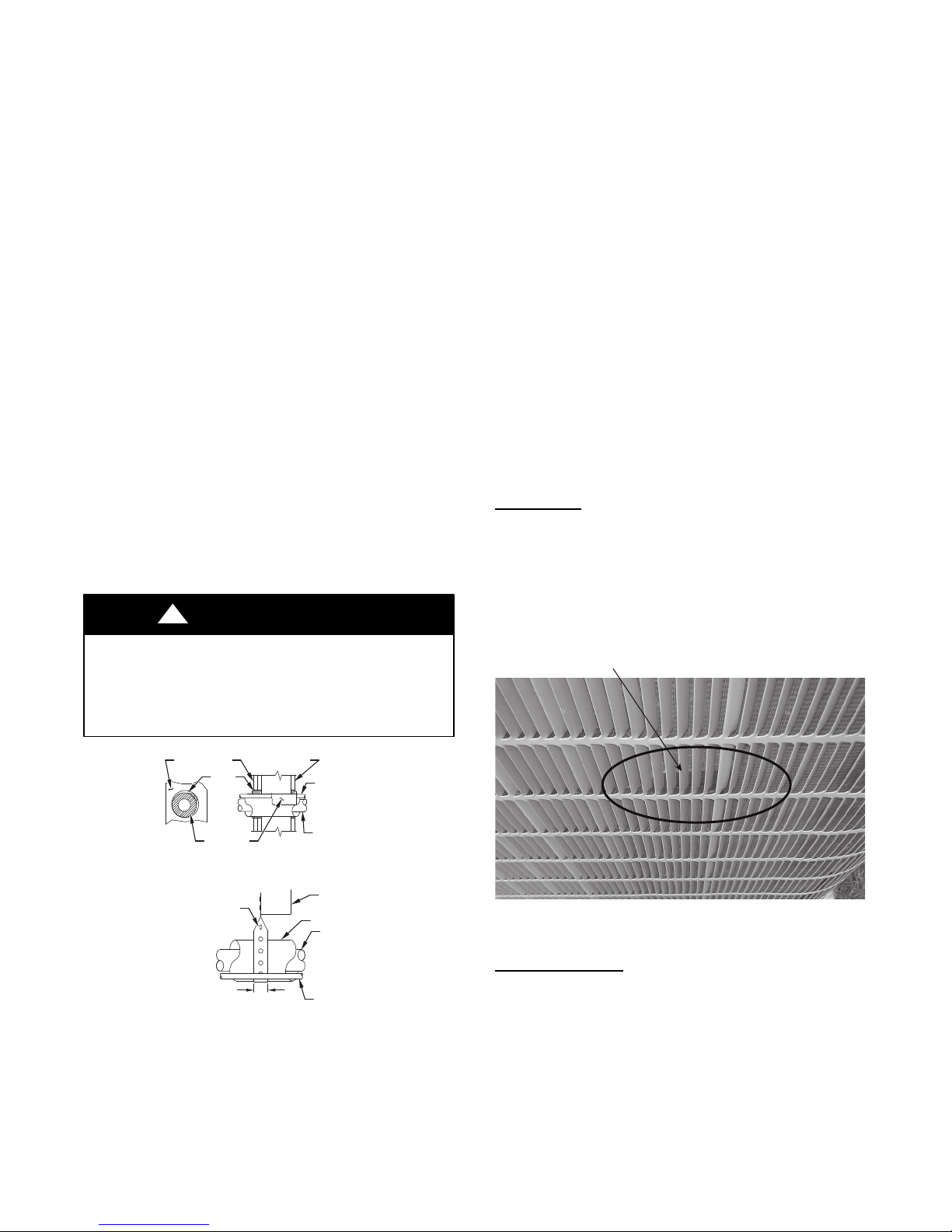
This unit employs one louver spacer on each of the four sides to
prevent louver movement during operation. The louver spacers are
trapped between the coil surface and louver at the approximate
center of each side (See Fig. 2). This louver spacer should be
present and, if dislodged during shipment, must be reinstalled
before unit is placed into operation.
Louver Spacer
OUTDOOR WALL INDOOR WALL
CAULK
INSULATION
HANGER STRAP
(AROUND SUCTION
TUBE ONLY)
1” (25.4 mm)
MIN
THROUGH THE WALL
SUSPENSION
LIQUID TUBE
SUCTION TUBE
JOIST
INSULATION
SUCTION TUBE
LIQUID TUBE
A07588
Fig. 1 -- Connecting Tubing Installation
The outdoor unit contains the correct amount of refrigerant charge
for operation with AHRI rated and factory--approved smallest
indoor unit when connected by 15 ft (4.57 m) of field--supplied or
factory accessory tubing.
A11380
Fig. 2 -- Louver Spacer Location
Inspect Equipment
File claim with shipping company prior to installation if shipment
is damaged or incomplete. Locate unit rating plate on unit corner
panel. It contains information needed to properly install unit.
Check rating plate to be sure unit matches job specifications.
3
Step 2 — Install on a Solid, Level Mounting Pad
Green
Yellow
White
ABCD
Connection (optional)
Red
LLS
LS
User Interface
Optional Remote
Room Sensor
Furnace or
Fan Coil
Vari able
Speed
HP
A
B
C
C
S2
A
B
C
D
A
B
C
D
S1
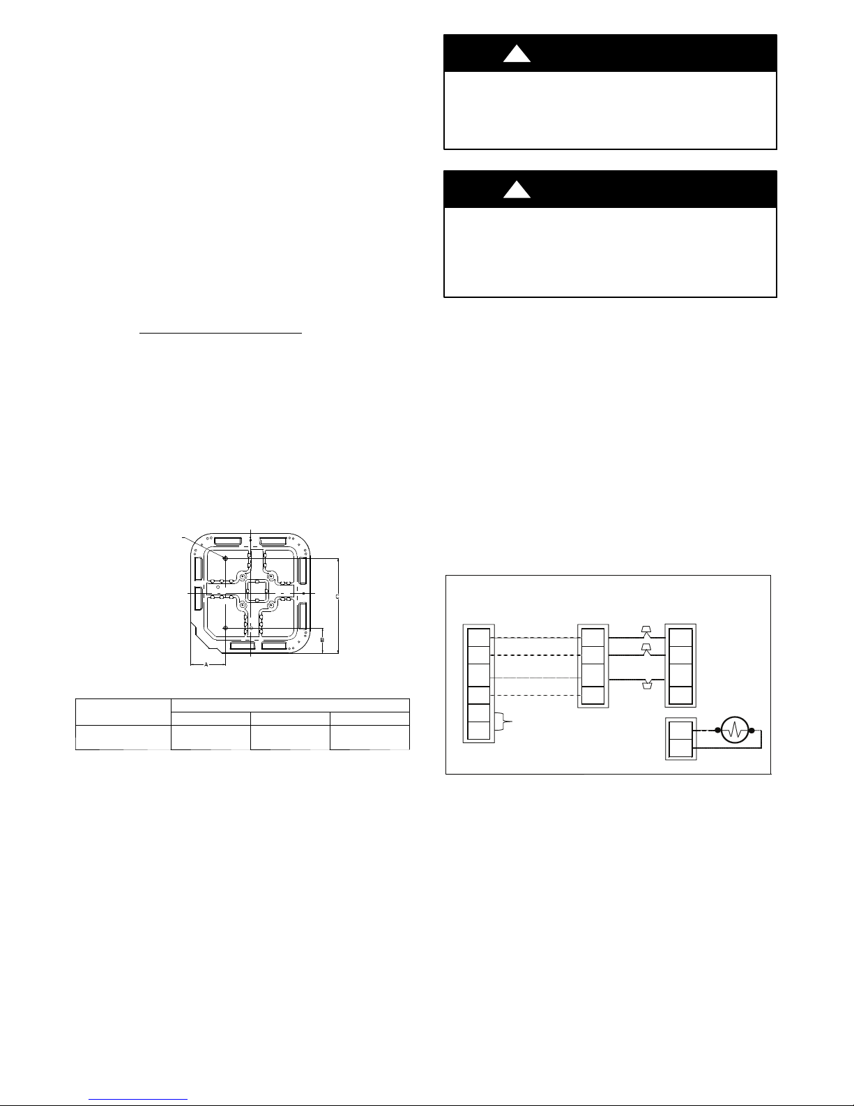
If conditions or local codes require the unit be attached to pad, tie
down bolts should be used and fastened through knockouts
provided in unit base pan. Refer to unit mounting pattern in Fig. 3
to determine base pan size and knockout hole location.
For hurricane tie downs, contact distributor for details and PE
(Professional Engineer) Certification, if required.
On rooftop applications, mount on level platform or frame. Place
unit above a load--bearing wall and isolate unit and tubing set from
structure. Arrange supporting members to adequately support unit
and minimize transmission of vibration to building. Consult local
codes governing rooftop applications.
Roof mounted units exposed to winds above 5 mph may require
wind baffles. Consult the Service Manual -- Residential Split
System Air Conditioners and Heat Pumps Using Puron
Refrigerant for wind baffle construction.
NOTE: Unit must be level to within 2 (3/8 in./ft,9.5 mm/m.)
per compressor manufacturer specifications.
Step 3 — Clearance Requirements
When installing, allow sufficient space for airflow clearance,
wiring, refrigerant piping, and service. Allow 24 in. (609.6 mm)
clearance to service end of unit and 48 in. (1219.2 mm) (above
unit. For proper airflow, a 6--in. (152.4 mm) clearance on 1 side of
unit and 12--in. (304.8 mm) on all remaining sides must be
maintained. Maintain a distance of 24 in. (609.6 mm) between
units. Position so water, snow, or ice from roof or eaves cannot fall
directly on unit.
On rooftop applications, locate unit at least 6 in. (152.4 mm) above
roof surface.
3/8---in. (9.53 mm) Dia.
Tiedown Knockouts in
Basepan(2) Places
!
CAUTION
UNIT OPERATION HAZARD
Failure to follow this caution may result in equipment
damage or improper operation.
Do not allow water and/or ice to build up in base pan.
!
CAUTION
UNIT OPERATION HAZARD
Failure to follow this caution may result in equipment
damage or improper operation.
Locate the unit in such a way that it is stable in all
circumstances including adverse weather conditions.
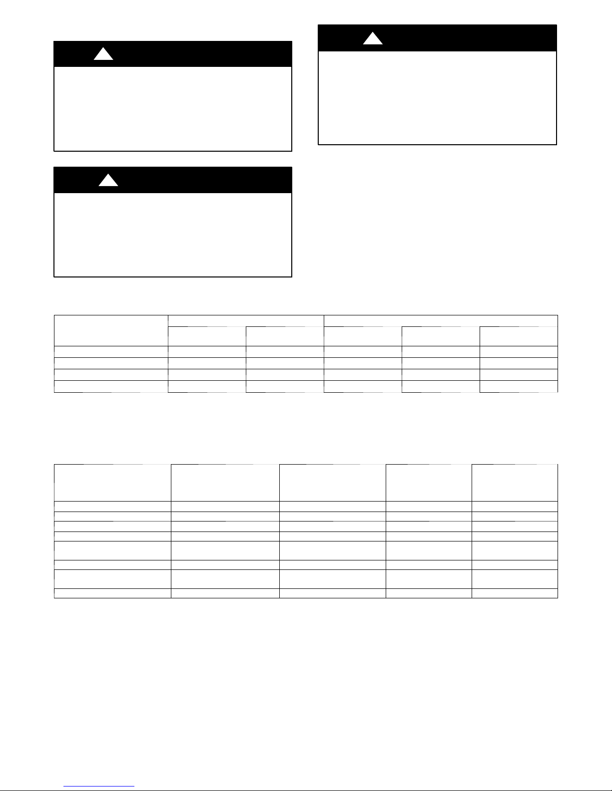
Step 6 — In Long--Line Applications, Install
Liquid--Line Solenoid Valve (LSV)
For refrigerant piping arrangements with equivalent lengths of
greater than 80 ft. (24.38 m) and/or when elevation difference
between indoor and outdoor unit is greater than 20 ft. (6.10 m),
follow the piping configuration and liquid line solenoid valve
(LSV) accessory requirements from the Residential Piping and
Long--line guideline. CCH, start gear and piston changes do not
apply. If required by Long--Line Guideline, install LSV kit, part
no. KHALS0401LLS, specifically designed for Puron refrigerant
heat pumps. LSV should be installed within 2 ft. (0.61 m) of
outdoor unit with flow arrow pointing toward outdoor unit.
Make the necessary electrical connections as shown on Fig. 21 and
by following the Installation Instructions included with accessory
kit.
IMPORTANT: Flow arrow must point toward outdoor unit.
View From Top
UNIT BASE PAN
Dimension in. (mm)
35 X 35
(889 X 889)
TIEDOWN KNOCKOUT LOCATIONS in. (mm)
A B C
9–1/8 (231.8) 6–9/16 (166.7) 28–7/16 (722.3)
Fig. 3 -- Tiedown Knockout Locations
Step 4 — Operating Ambient
The minimum outdoor operating ambient in cooling mode is 55_F
(12.78_C) without low ambient cooling enabled, and the
maximum outdoor operating ambient in cooling mode is 125_F
(51.67_C). The maximum heating operation ambient is 66_F
(18.9_C). Compressor protections prevent operation below --10 to
-- 2 0 _F.
Step 5 — Elevate Unit
Elevate unit per local climate and code requirements to provide
clearance above estimated snowfall level and ensure adequate
drainage of unit.
A05177
No
Use
Fig. 4 -- Liquid Line Solenoid Electrical Connection
(Required for long line applications)
4
A12053
Step 7 — Make Piping Connections
!
PERSONAL INJURY AND UNIT DAMAGE
HAZARD
Failure to follow this warning could result in personal injury or
death.
Relieve pressure and recover all refrigerant before system
repair or final unit disposal. Use all service ports and open all
flow--control devices, including solenoid valves.
!
UNIT DAMAGE HAZARD
Failure to follow this caution may result in equipment
damage or improper operation.
Do not leave system open to atmosphere any longer than
minimum required for installation. POE oil in compressor is
extremely susceptible to moisture absorption. Always keep
ends of tubing sealed during installation.
WARNING
CAUTION
Table 1 – Refrigerant Connections and Recommended Liquid and Vapor Tube Diameters (in.)
!
CAUTION
UNIT DAMAGE HAZARD
Failure to follow this caution may result in equipment
damage or improper operation.
If ANY refrigerant tubing is buried, provide a 6 in. (152.4
mm) vertical rise at service valve. Refrigerant tubing lengths
up to 36 in. (914.4 mm) may be buried without further
special consideration. Do not bury lines longer than 36 in.
(914.4 mm).
Outdoor units may be connected to indoor section using accessory
tubing package or field--supplied refrigerant grade tubing of correct
size and condition. For tubing requirements beyond 80 ft. (24.38
m), substantial capacity and performance losses can occur. Follow
the pipe sizing recommendations in the 280ANV Product data to
manage these losses.
Refer to Table 1 for field tubing diameters. Refer to Table 2 for
accessory requirements.
UNIT SIZE
280ANV024
280ANV036
280ANV048
280ANV060
* Units are rated with 25 ft. (7.6 m) of lineset. See Product Data sheet for performan ce data when using different size and length line sets.
Notes:
1. Do not apply capillary tube indoor coils to these units.
2. For Tubing Set lengths between 80 a nd 200 ft. (24.38 and 60.96 m) horizontal and / or greater than 20 ft. ( 6.1 m) vertical differential, an accessory Liquid Line
Solenoid must be installed.
Connection
Diameter
3/8 3/8 7/8 7/8 5/8
3/8 3/8 7/8 7/8 5/8
3/8 3/8 7/8 1 --- 1/ 8 3/4
3/8 3/8 7/8 1 --- 1/ 8 3/4
LIQUID VAPOR*
Tube
Diameter
Connection
Diameter
Max (Rated)
Diameter
Minimum Tube
Diameter
Table 2 – Accessory Usage
REQUIRED FOR
ACCESSORY
Crankcase Heater Standard
Evaporator Freeze Protection Standard with Evolution Control No No No
Liquid--- Line Solenoid Valve No
Low--- Ambient Control Standard with Evolution Control No No No
Puron Refrigerant Balance Port
H a r d --- S h u t O f f T X V
Support Feet Recommended No Recommended No
Winter Start Control
EMI Kit No No No Ye s
* For tubing set lengths between 80 and 200 ft. (24.38 and 60.96 m) horizontal or 20 ft. (6.10 m) vertical differential (total equivalent length), an accessory
Liquid Line Solenoid must be installed.
{ Required on all indoor units. Standard on all new Puron refrigerant fan coils and furnace coils.
Standard = Standard for all new Puron refrigerant fan coils and furnace coils.
L O W --- A M B I E N T C O O L I N G
APPLICATIONS
(Below 55F/12.8_C)
Ye s{
Standard with Evolution
Control
REQUIRED FOR LONG LINE
APPLICATIONS*
(Over 80 ft/24.38 m)
Standard
Yes
Ye s{
Standard with Evolution
Control
REQUIRED FOR SEA
COAST APPLICATIONS
(Within 2 miles/3.22 km)
Standard Standard
No No
Ye s{ Ye s{
Standard with Evolution
Control
Installations with Radio
Frequency Interference
Concerns in the Range
of2to30MHZ
Standard with Evolution
Control
5
Outdoor Unit Connected to Factory--Approved Indoor
Unit
Outdoor unit contains correct system refrigerant charge for
operation with factory--approved, AHRI--rated smallest indoor unit
when connected by 15 ft. (4.57 m) of field--supplied or
factory--accessory tubing, and factory--supplied filter drier. Check
refrigerant charge for maximum efficiency.
NOTE: If the indoor furnace coil width is more than the furnace
casing width, refer to the indoor coil Installation Instructions for
transition requirements.
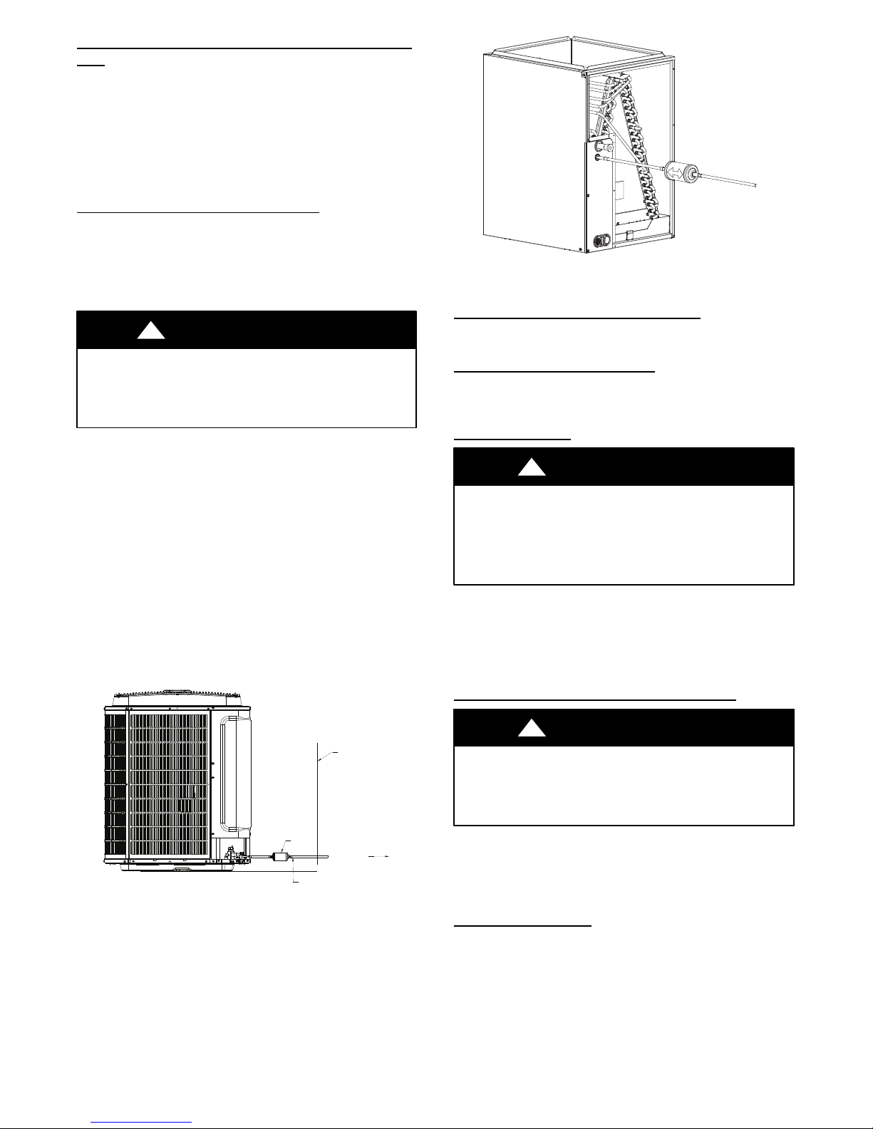
Install Liquid--Line Filter Drier Indoor
Refer to Fig. 6 and install filter drier as follows:
1. Braze 5--in. (127 mm) liquid tube to the indoor coil.
2. Wrap filter drier with damp cloth.
3. Braze filter drier to above 5--in. (127 mm) liquid tube.
4. Connect and braze liquid refrigerant tube to the filter drier.
!
UNIT DAMAGE HAZARD
Failure to follow this caution may result in unit damage or
improper operation.
Installation of filter drier in liquid line is required.
CAUTION
Factory Supplied Muffler (part # LM10KK003)
Installation is Required On Every Installation:
S A muffler isrequired to reduce noise transmitted toindoor through
the line set.
S Muffler must be installedoutside thedwelling. Muffler can also be
installed in vertical configuration for space consideration
maintaining a minimum of 12 in (304.8 mm) straight pipesection
to the closest bend.
S Maintain at least 12 in. (304.8 mm) straight pipe length to the
muffler shell inlet and from the outlet stubs.
S To prevent rusting, provide sufficient clearance between the
mufflerandtheground surface. Also, position the mufflersuch that
accidental abuse (such as by a weed trimmer, lawn mower etc.) of
the painted surface is avoided. Apply touch--up paint to muffler
braze joints.
S Insulating the muffler with Armaflext tape is recommended.
A05227
Fig. 6 -- Liquid--Line Filter Drier
Refrigerant Tubing connection Outdoor
Connect vapor tube to fitting on outdoor unit vapor service valves
(see Table 1).
NO Installation of Adapter Tube
Although it is a heat pump this unit has a standard AC liquid
service valve. An EXV inside the unit serves as the heating
expansion device.
Sweat Connections
!
UNIT DAMAGE HAZARD
Failure to follow this caution may result in equipment
damage or improper operation.
S Use a brazing shield
S Wrap service valves with wet cloth or heat sink material.
Use refrigerant grade tubing. Service valves are closed from factory
and ready for brazing. After wrapping service valve with a wet
cloth, braze sweat connections using industry accepted methods
and materials. Consult local code requirements. Refrigerant tubing
and indoor coil are now ready for leak testing. This check should
include all field and factory joints.
CAUTION
Evacuate Refrigerant Tubing and Indoor Coil
MUFFLER
Fig. 5 -- Muffler Installation
VAPOR LINE
EXTERIOR
WALL
TO DWELLING
A12044
!
UNIT DAMAGE HAZARD
Failure to follow this caution may result in equipment
damage or improper operation.
Never use the system compressor as a vacuum pump.
Refrigerant tubes and indoor coil should be evacuated using the
recommended deep vacuum method of 500 microns. The alternate
triple evacuation method may be used. See Service Manual for
triple evacuation method. Always break a vacuum with dry
nitrogen prior to opening the refrigerant system for servicing.
CAUTION
Deep Vacuum Method
The deep vacuum method requires a vacuum pump capable of
pulling a vacuum of 500 microns and a vacuum gauge capable of
accurately measuring this vacuum depth. The deep vacuum method
is the most positive way of assuring a system is free of air and
liquid water. (See Fig. 7)
6
 Loading...