

Bryant Evolution Connex SYSTXBBECW01-A, Evolution Connex SYSTXBBECN01-A, Evolution Connex SYSTXBBECC01-A Installation Instructions Manual
SYSTXBBECW01--A, SYSTXBBECN01--A
& SYSTXBBECC01--A
Evolutionr Connext Control
Installation Instructions
A12479
NOTE: Read the entire instruction manual before starting the installation.
The features and functions outlined in the Installation Instructions reflect Version 11
software. See the Evolution Connex product page on the HVACPartner.com
website or the Downloads section of the www.MyEvolutionConnex.Bryant.com
website for the latest software release.
US Patents: Carrier U.S. Pat No. 7,243,004, Carrier U.S. Pat No. 7,775,452, pointSETt U.S.
Pat No. 7,415,102


TABLE OF CONTENTS
PAGE
1.Safety Considerations 1.............................................
2.Introduction 1.....................................................
3.Quick Start 2......................................................
3.1.Set Time and Date 2............................................
3.1.1. Manually Adjust Time and Date 3............................
3.1.2. Setup Time Zone 4........................................
3.1.3. Enable Time Synchronization 4..............................
3.2. Set Dealer Information 5........................................
4.Installation 6......................................................
4.1.Overview 6...................................................
4.2.Check Equipment 6............................................
4.3.Location 7....................................................
4.3.1. Wall Control 7...........................................
4.3.2. Remote Room Sensors 8...................................
4.3.2.1.Remote Room Sensor Averaging 8...........................
4.3.3. Smart Sensors (for zoning applications) 9......................
4.4.Wiring Considerations 9.........................................
4.4.1. Shielded Wire 12.........................................
4.4.2. Damper Control Module 13.................................

TABLE OF CONTENTS (cont.)
PAGE
4.5.Mounting 13..................................................
4.5.1. Decorative Backplate 14...................................
4.6.Humidifier Connections 15......................................
4.6.1. Bypass Humidifier 15......................................
4.6.2. Fan Powered Humidifiers 15................................
5.Commissioning 16.................................................
5.1.Searching for Indoor Unit 16.....................................
5.2.Searching for Outdoor Unit 17....................................
5.3.Indoor Evaporator Selection 18...................................
5.4.Electric Heater Selection 18......................................
5.4.1. Hydronic Heat Application 19...............................
5.5.Searching SAM Module (If Applicable) 20..........................
5.6.Searching for Zones (If Applicable) 20.............................
5.7. Filter Type Selection 21.........................................
5.8.Humidifier Installation 21........................................
5.9. Ultraviolet Lights Installation 21..................................
5.10.Equipment Summary 21........................................
5.11.Airflow Verification Check 22....................................
5.12.Duct Assessment (zoning applications only) 22......................

TABLE OF CONTENTS (cont.)
PAGE
6.Service Menu 24...................................................
6.1.Equipment Summary 25.........................................
6.2. Installation 25.................................................
6.3.Set up 26.....................................................
6.3.1. Thermostat 27............................................
6.3.1.1.Auto Mode set up 28......................................
6.3.1.2.Heat/Cool Deadband 28...................................
6.3.1.3.Offsets 28..............................................
6.3.1.4.Reset factory defaults 29...................................
6.3.1.5.Scheduling Enable 29.....................................
6.3.1.6.Smart Recovery Enable 29.................................
6.3.2. Fan Coil 29..............................................
6.3.2.1.Airflow 30..............................................
6.3.2.2.Altitude 31.............................................
6.3.2.3.Fan Coil Dehumidification 31...............................
6.3.2.4.Fan Coil G--Terminal 32...................................
6.3.2.5.Fan Coil G--Terminal Alert 32...............................
6.3.2.6.Fan Coil G--Terminal Label 33..............................

TABLE OF CONTENTS (cont.)
PAGE
6.3.3. Furnace 34..............................................
6.3.3.1.Furnace Airflow 35.......................................
6.3.3.2.AC/HP Air Flow 35.......................................
6.3.3.3.Furnace Staging 36.......................................
6.3.3.4.Furnace Airflow Limits (modulating furnace only) 36............
6.3.3.5.Furnace Off Delay 37.....................................
6.3.3.6.Altitude 37.............................................
6.3.3.7.Furnace Dehumidifier Drain 38.............................
6.3.3.8.Furnace G Terminal 38....................................
6.3.3.9.Furnace G Terminal Alert 39...............................
6.3.3.10.Furnace G Terminal Alert Label 39.........................
6.3.4. AC/Heat Pump 40........................................
6.3.4.1.Latching 40.............................................
6.3.4.2.Cooling Lockout 41......................................
6.3.4.3.Defrost Interval 42.......................................
6.3.4.4.Low Ambient Cooling 42..................................
6.3.4.5.Quiet Shift 42...........................................
6.3.4.6.AC/Heat Pump RPM Max 42...............................
6.3.4.7.Defrost Fan Delay 43.....................................

TABLE OF CONTENTS (cont.)
PAGE
6.3.4.8.Brownout Disable 43.....................................
6.3.4.9.Low Air Multiplier 43.....................................
6.3.5. Heat Source Lockout 44....................................
6.3.6. Stages / Latch for Evolution V 44.............................
6.3.7. Zoning (If Applicable) 45...................................
6.3.7.1.Zoning Disable 45........................................
6.3.7.2.Zone Offsets 46..........................................
6.3.7.3.Zone Airflow Limits 46....................................
6.3.7.4.Duct Assessment Time 46..................................
6.3.8. Accessories 47...........................................
6.3.8.1.Filter 47................................................
6.3.8.2.Humidifier 48...........................................
6.3.8.3.Ultraviolet Lights 48......................................
6.3.8.4.Ventilator 48............................................
6.3.9. Utility Curtailment 49......................................
6.3.10. Hydronic Airflow 49......................................
6.4.Check out 50.................................................
6.4.1. Electric Heat 51..........................................
6.4.2. Furnace 51..............................................

TABLE OF CONTENTS (cont.)
PAGE
6.4.3. Hydronic 52.............................................
6.4.4. Air Conditioning 52.......................................
6.4.5. Heat Pump Heating 53.....................................
6.4.6. Heat Pump Cooling 54.....................................
6.4.7. Humidifier 54............................................
6.4.8. Ventilator 55.............................................
6.4.9. Zoning (If Applicable) 55...................................
6.4.9.1.Airflow Limits 55........................................
6.4.9.2.Damper/Sensor Check 55..................................
6.4.9.3.Zone Duct Assessment 56..................................
6.4.9.4.Sensor Type 56..........................................
6.5.Service Information 56..........................................
6.5.1. Advanced Diagnostics 57...................................
6.5.2. Fan Coil Status 57........................................
6.5.3. Furnace Status 58.........................................
6.5.4. AC Status 58.............................................
6.5.5. Heat Pump Status 59......................................
6.5.6. Zoning Status 59..........................................
6.5.7. Last 10 System Events 60...................................

TABLE OF CONTENTS (cont.)
PAGE
6.5.8. Run/Fault History 61......................................
6.5.9. Model/Serial Numbers 61...................................
6.5.10. Service Phone Number 62..................................
6.6.Refrigerant Charging (Evolution Extreme Only) 63....................
6.6.1. Charging 63.............................................
6.6.2. Pump down 64...........................................
6.6.3. Evacuation 64............................................
6.7.Refrigerant Charging Evolution V 65...............................
6.7.1. Charging 66.............................................
6.7.2. Pump down 67...........................................
6.7.3. Evacuation 67............................................
6.7.4. EXV Position 68..........................................
6.8.Dealer Logo 68................................................
6.9. Utility Event Setup 69..........................................
7.Wireless Setup 70..................................................
7.1.SYSTXBBECC01--A Model (only) 71..............................
7.2.SYSTXBBECW01--A Model (only) 74.............................
8.Appendix A -- Wiring Diagrams 79....................................
NOTE: See the Owner’s Manual for information regarding software upgrades.

1
1. Safety Considerations
Improper installation, adjustment, alteration, service, maintenance, or use can cause
explosion, fire, electrical shock, or other conditions which may cause death,
personal injury or property damage. Consult a qualified installer, service agency or
your distributor or branch for information or assistance. The qualified installer or
agency must use factory--authorized kits or accessories when modifying this HVAC
system. Refer to the individual instructions packaged with the kits or accessories
when installing.
Follow all safety codes. Wear safety glasses, protective clothing, and work gloves.
Have a fire extinguisher available. Read these instructions thoroughly and follow
all warnings and cautions included in literature and attached to the unit. Consult
local building codes and the current edition of the National Electrical Code (NEC)
NFPA 70. In Canada, refer to the current editions of the Canadian Electrical Code
CSA C22.1.
Recognize safety information. When you see this symbol
on the unit and in
instructions or manuals, be alert to the potential for personal injury. Understand the
signal words DANGER, WARNING,andCAUTION. These words are used with
the safety--alert symbol. DANGER identifies the most serious hazards, which will
result in severe personal injury or death. WARNING signifies hazards, which could
result in personal injury or death. CAUTION is used to identify unsafe practices,
which may result in minor personal injury or product and property damage. NOTE
is used to highlight suggestions which will result in enhanced installation,
reliability, or operation.
2. Introduction
The Evolutionr System consists of several intelligent communicating components
which include the Evolutionr Connext Control (or User Interface), variable speed
furnace or FE fan coil, and 2--stage AC or HP, which continually communicate with
each other via a four--wire connection called the ABCD bus. Commands, operating

2
conditions, and other data are passed continually between components over the
ABCD bus. The result is a new level of comfort, versatility, and simplicity.
All Evolutionr furnaces or fan coils are variable--speed and multi stage for
maximum flexibility, efficiency, and comfort. They support controlled ventilation,
humidification, dehumidification, and air quality control. Either an Evolutionr
(communicating), or a standard single--stage 24VAC controlled outdoor unit may be
used.
When using a Bryant HRV or ERV with a zoned system, the Evolutionr Zone
board allows connection of a Bryant HRV or ERV without the need for separate
wall control.
When using conventional single--stage outdoor units, the Evolution furnace or fan
coil provides the 24 volt signals needed to control them. Also, the Evolutionr
Network Interface Module (P/N SYSTXBBNIM01) allows connection of a Bryant
HRV or ERV without the need for separate wall control.
All system components are controlled through the wall mounted Evolution Connex
Control, which replaces the conventional thermostat and provides the homeowner
with a single wall control for all features of the system.
3. Quick Start
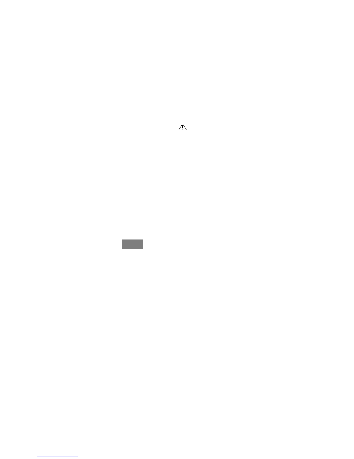
3.1. Set Time and Date
The time and date can either be set manually or can be synchronized with the web
server (only for Wi--Fi enabled units). From the main screen, touch MENU,onthe
bottom of the control. The TIME/DATE icon will bring up the time and date menu.
3
A14215
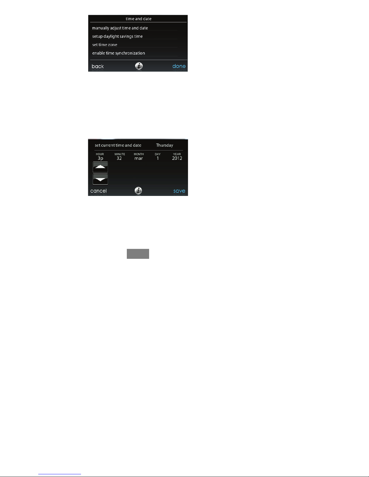
3.1.1. Manually Adjust Time and Date
d To s et th e HOUR, MINUTE, MONTH, DAY, or YEAR touch the feature
you wish to change.
d Use the Up (Y) and Down (B) buttons to make the appropriate changes.
d When you have completed all of the settings touch SAVE.
A14216
4
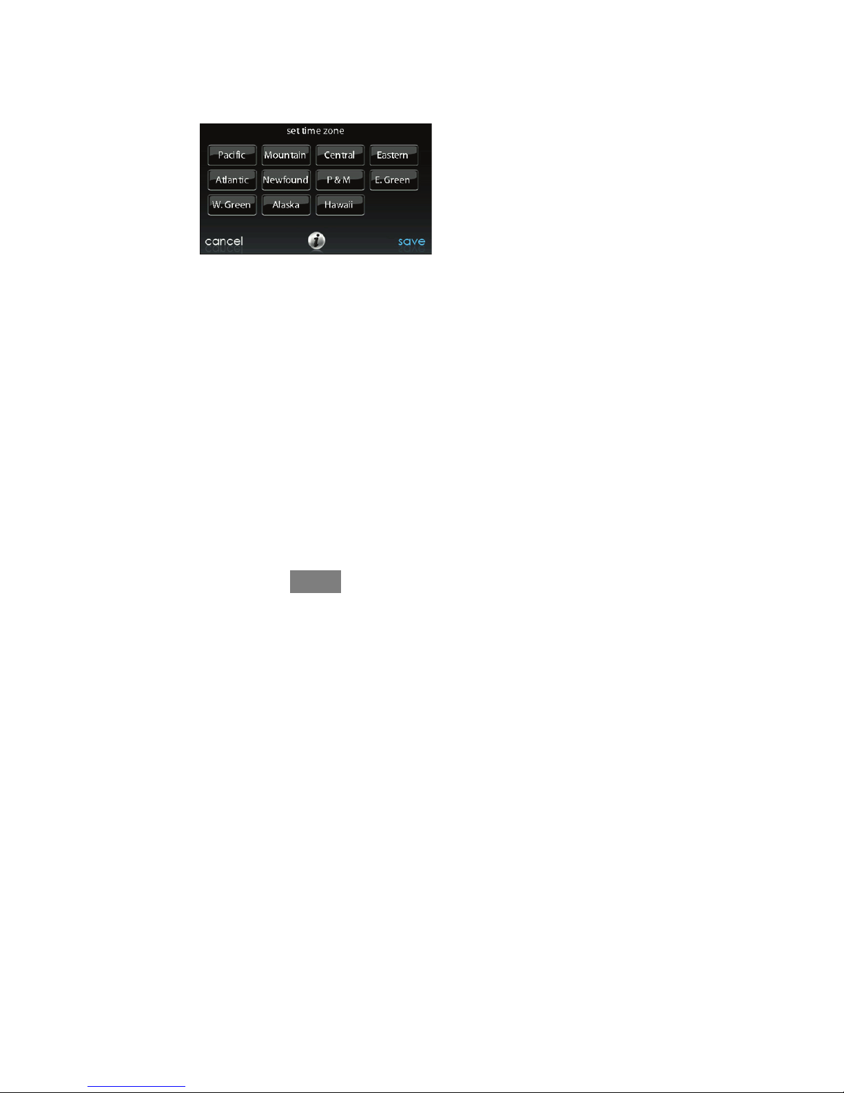
3.1.2. Setup Time Zone
The time zone can be selected by selecting the setup time zone from the menu.
Then select the time zone for the location. Time zones for both US and Canada are
included.
A14217
3.1.3. Enable Time Synchronization
After setting up the time zone, the time synchronization can then be done. Both
setting the time zone and enabling time synchronization must be done in order to
enable time synchronization.
5
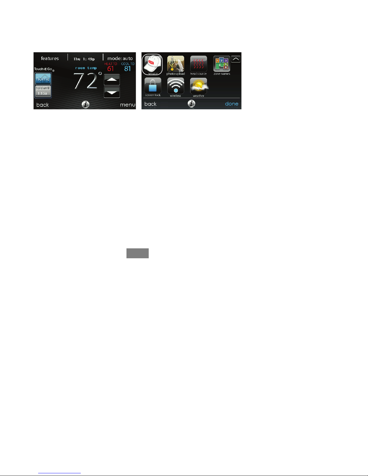
3.2. Set Dealer Information
From the main screen, touch MENU, on the bottom of the control. The SERVICE
icon allows you to upload your contact information into the Evolution Connex
Control.
A14274
S Format your contact information and logo (if applicable) using the PC/MAC
application, save it to a standard USB drive. See Section 6.7.
S Touch the SERVICE icon for about 10 seconds, then touch DEALER LOGO
UPLOAD.
S Place the USB drive into the USB port on the bottom of the Evolution Connex
Control and follow the on screen prompts.
S More detailed information can be found on HVACPartners.com under the
Product tab> Thermostats & Controls> SYSTXBBECW01> Documents &
Downloads> Marketing/Miscellaneous> Evolution Connex Control Dealer
Logo Application -- Instructions.

6
4. Installation
4.1. Overview
This instruction covers installation of the Evolutionr Connext Control and the
Evolutionr Wireless Access Point only. Physical installation instructions for the
indoor and outdoor equipment, and accessories are provided with each unit.
Setup, commissioning, operation, and troubleshooting of the Evolutionr System are
covered only in this installation instruction. It is the guide to connecting the system
components and commissioning the system once all physical components are
installed. Special screen prompts and start--up capabilities are provided in the
Evolution System to simplify and automate the initial commissioning of the system.
S Install the Evolution Connex Control according to this instruction.
S Install indoor unit, outdoor unit, and accessories according to their instructions.
S Wire complete system according to this instruction.
S Setup, commission, and operate system according to this instruction to assure a
smooth and trouble free start--up.
4.2. Check Equipment
Inspect equipment. File a claim with shipping company prior to installation if
shipment is damaged or incomplete.
7
4.3. Location
ELECTRICAL OPERATION HAZARD
Failure to follow this warning could result in personal injury
or death.
Disconnect power before routing control wiring.
!
WARNING
All wiring must comply with national, local, and state codes.
4.3.1. Wall Control
The Evolution Connex Control is the command center for the Evolution System. It
should be located where it is easily accessible and visible to the adult homeowner
or end user. For accurate temperature measurement, the following guidelines should
be followed:
The Evolution Connex Control and Remote Room Sensors SHOULD be mounted:
S Approximately 5--ft (1.5 m) from the floor.
S Close to or in a frequently used room, preferably on an inside partitioning wall.
S On a section of wall without pipes or ductwork.
The Evolution Connex Control and Remote Room Sensors SHOULD NOT be
mounted:
S Close to a window, on an outside wall, or next to a door leading to the outside.
S Exposed to direct light or heat from a lamp, sun, fireplace, or other
temperature--radiating objects which could cause a false reading.

8
S Close to or in direct airflow from supply registers.
S In areas with poor air circulation, such as behind a door or in an alcove.
4.3.2. Remote Room Sensors
A Remote Room Sensor can be used with the Evolution Connex Control to take the
place of the control’s internal temperature sensor. This allows the Evolution Connex
Control to be mounted in areas with less than optimal airflow (such as near an
exterior door, window or in a closet). The remote sensor can be wired to the
terminal block connectors labeled S1 and S2 at the control’s backplate, or the ZS1
and ZS1C connection at the Damper Control Module. In either case, the Evolution
Connex Control will automatically detect the Remote Room Sensor and ignore its
internal temperature sensor.
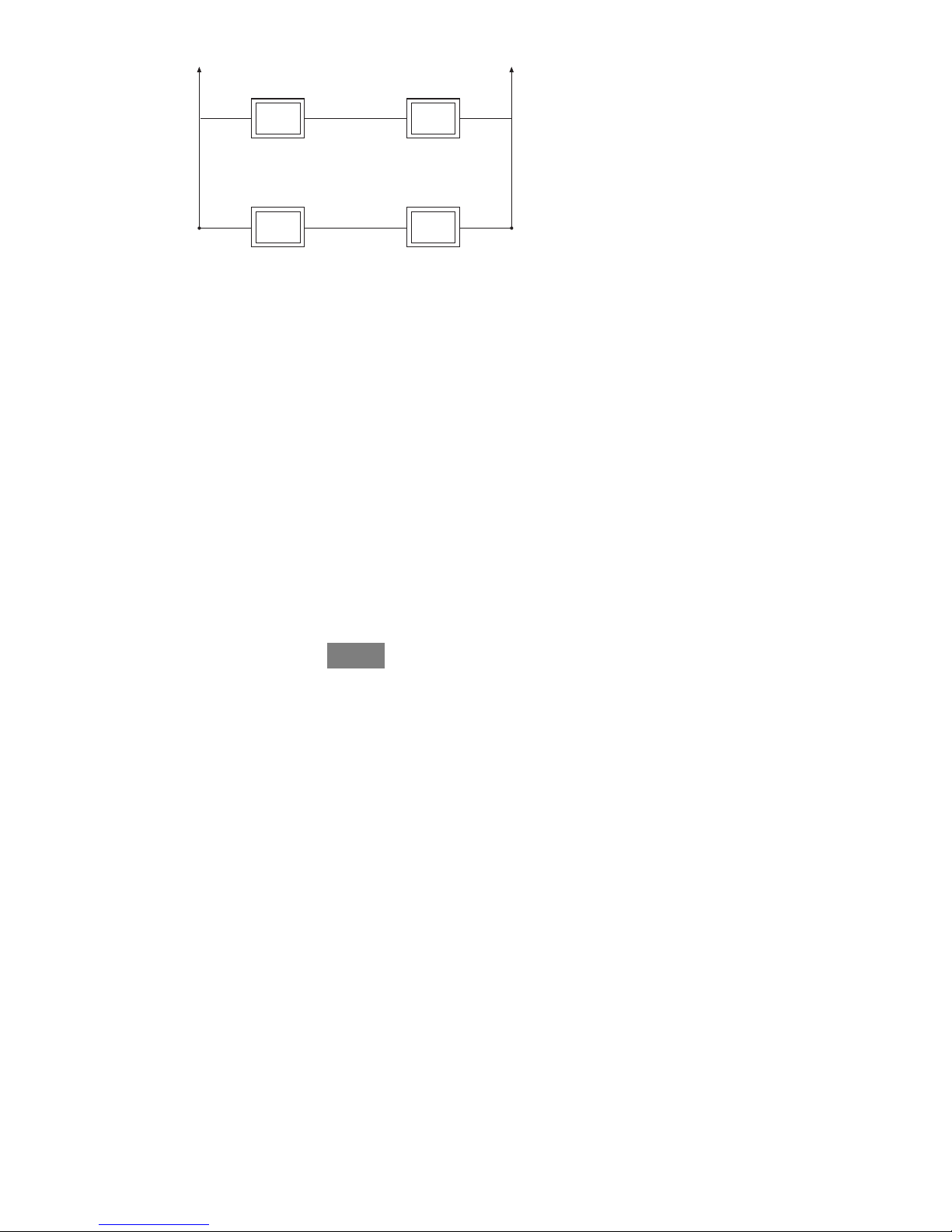
4.3.2.1. Remote Room Sensor Averaging
Typically, one remote sensor is used but, multiple sensors may be used and
averaged in some applications. Averaging requires a special series--parallel wiring
method with a specific number of sensors. See figure below. It is also important to
note the humidity sensor cannot be remotely located, so do not locate the Evolution
Control in an area where humidity sensing may not be accurate.
9
Sensor 1 Sensor 2
Sensor 3 Sensor 4
Damper Control
Module
ZS_
Damper Control
Module
ZS_C
A03233
4.3.3. Smart Sensors (for zoning applications)
Any zone may use a Smart Sensor. It provides a temperature display and buttons to
adjust the desired temperature in that zone only. It also displays outdoor
temperature and indoor humidity sensed at the control. Only one Smart Sensor may
be used per zone. They cannot be averaged like Remote Room Sensors. If a Smart
Sensor is used in a zone, a Remote Room Sensor may also be used in the same
zone. The Remote Room Sensor has priority over the Smart Sensor. The Smart
Sensor will display the Remote Room Sensor temperature.
NOTE: Smart Sensors must be addressed to identify which zone it will control. See
Smart Sensor Installation Instructions for details.
4.4. Wiring Considerations
Ordinary thermostat wire is recommended. Use 22 AWG or larger for normal
wiring applications. Continuous wire lengths over 100 ft. should use 20 AWG or
larger.
10
NOTE: ABCD bus wiring only requires a four--wire connection; however, it is
good practice to run thermostat cable having more than four wires in the event of a
damaged or broken wire during installation.
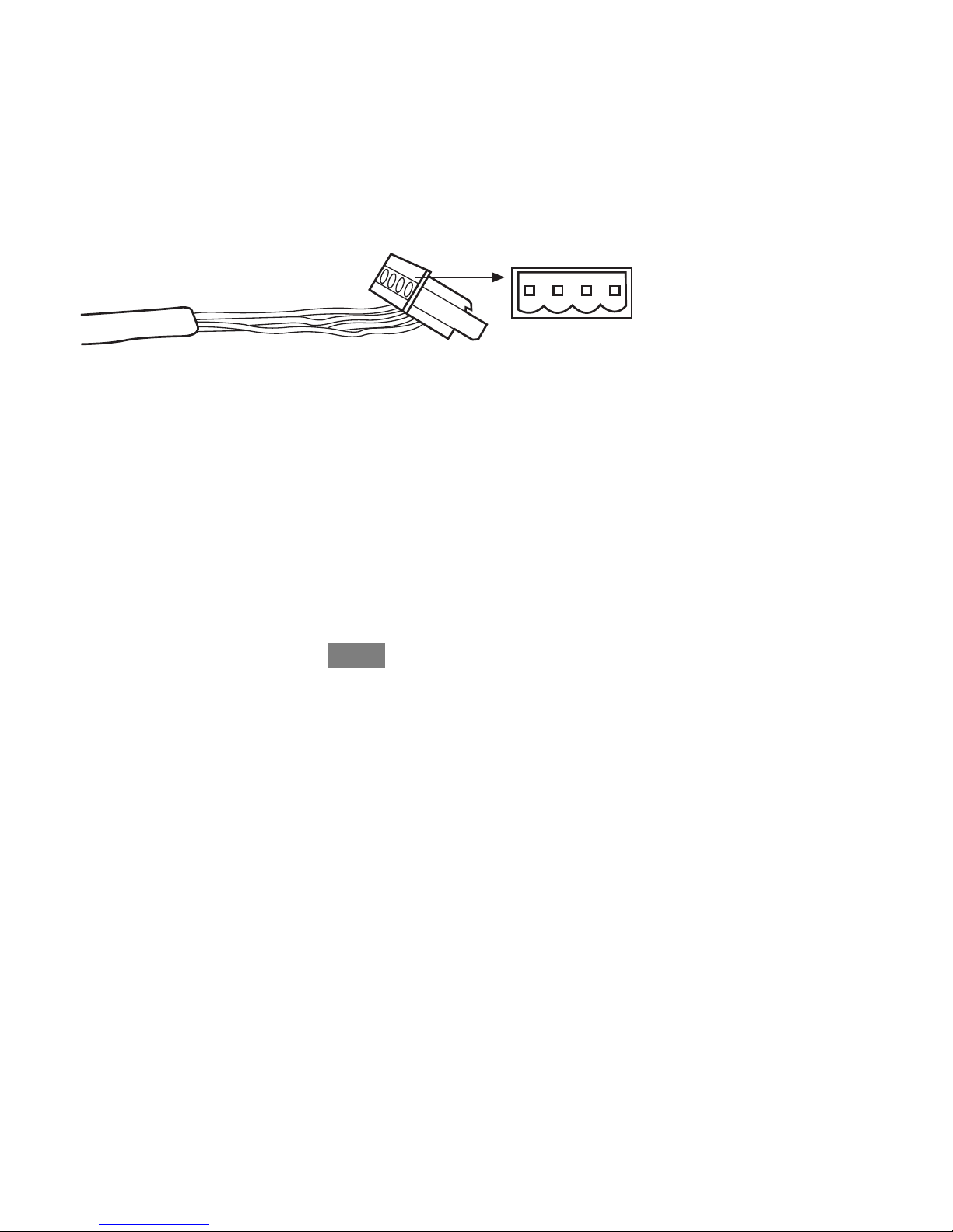
Each communicating device in the Evolutionr Zone System has a four--pin
connector labeled ABCD. It is recommended that the following color code be used
when wiring each device:
A — Green = Data A
B — Yellow = Data B
C — White = 24VAC (Com)
D — Red = 24VAC (Hot)
ABCD
A03193
It is not mandatory that the above color code be used, but each ABCD connector in
the system MUST be wired consistently.
NOTE: Some outdoor units provide their own low--voltage power source and do
not require the “C” (24VAC common) and “D” (24VAC power) connections. See
the outdoor unit installation instructions for more information.
11
ELECTRICAL OPERATION HAZARD
Failure to follow this warning could result in personal injury
or death.
Before installing, modifying, or servicing system, the main
electrical disconnect switch must be in the OFF position. There
may be more than 1 disconnect switch. Lock out and tag
switch with a suitable warning label.
!
WARNING
S Turn off all power to equipment.
S If an existing Evolutionr Control or other control is being replaced:
d Remove existing control from wall.
d Disconnect wires from existing control.
d Discard or recycle old control.
S NOTE: Mercury is a hazardous waste, if existing control contains any
mercury, it MUST be disposed of properly. The Evolution Connex
Control does not contain mercury.
S Select Evolution Control mounting plastic (backplate and decorative backplate
if desired).
S Route wires through large hole in mounting plastic. Level rear plastic against
wall (for aesthetic value only; Evolution Connex Control need not be level to
operate properly) and mark wall through two mounting holes.
S Drill two 3/16--in (4.8 mm) mounting holes in wall where marked.
S Secure mounting plastic to wall using two screws and anchors provided.

12
S Adjust length and routing of each wire to reach each wire entry on the
connector backplate. Strip 1/4--in (6.4 mm) of insulation from each wire.
S Match and connect thermostat wires to proper terminals on control backplate.
d See wiring diagrams in Appendix A.
S Push any excess wire into the wall. Seal hole in wall to prevent any air leaks.
Leaks can affect operation.
S Attach Evolution Control to the mounting plastic by lining up the plastic guides
on the back of the control with the opening on the mounting plastic and push
on.
S Perform installation of all other system equipment (i.e. dampers, humidifier,
ventilator, UV lights, etc.).
S Turn on power to equipment.
4.4.1. Shielded Wire
If the thermostat wiring will be located near or in parallel with high voltage wiring,
radio, TV or Ethernet wiring, then four conductor, twisted--pair, shielded cable can
be used to reduce or eliminate potential interference. The shield wire should be
connected to the C terminal, or ground, at the indoor unit. The shield wire should
NOT be connected to any terminal at the user interface. Connecting the shield to
ground at both ends can cause current loops in the shield, reducing shield
effectiveness.
Connect one pair of the two--pair (minimum) cable to the A and B communication
terminals, and another pair to the C and D terminals at both ends of the cable. The
shield wire should ONLY be connected at the indoor equipment ground or C
terminal. Note that some outdoor units only require the A and B connections. See
the outdoor unit installation instructions for more information.
13
4.4.2. Damper Control Module (zoning systems only)
All zoning wiring is run back to the Damper Control Module. Select a location near
the furnace or fan coil where wiring from the control, each Remote Room Sensor or
Smart Sensor, each damper actuator, and the equipment itself can come together
easily. The Damper Control Module is approved for indoor use only and should
never be installed with any of its components exposed to the elements. The Damper
Control Module (and zone dampers) may be installed in any area where the
temperature remains between --4_F to 158_F(--20_Cto70_C), and there is no
condensation. The cover must be installed to prevent damage from other sources.
Do not locate where it will be accessible to children. It may be mounted in either
vertical or horizontal position. Remember that wiring access is likely the most
important consideration.
PERSONAL INJURY HAZARD
Failure to follow this caution may result in personal injury.
To prevent possible damage to the Damper Control Module,
DO NOT mount on plenum, ductwork, or flush against
furnace or fan coil.
CAUTION
!
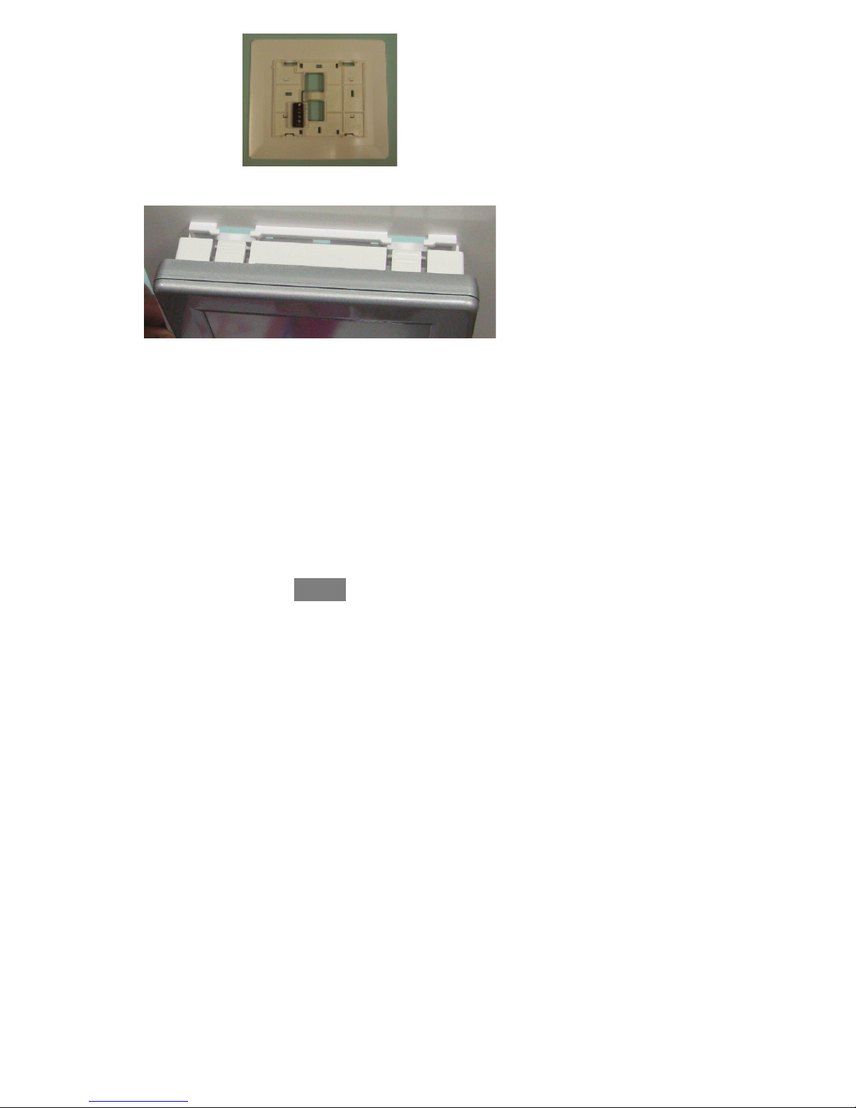
4.5. Mounting
First become familiar with all plastic assembly pieces shown on the following page.
The Evolution Connex Control will snap together with the backplate. A backplate is
supplied. Attach backplate using only a small hole in the wall allowing a four wire
connection to pass through. Mount the assembly to the backplate.
14
A12214
A12215
NOTE: Once Evolution Control is secured to wall with the backplate assembly
(snapped together), care must be taken not to bend or break the interlocking tabs
when removing.
4.5.1. Decorative Backplate
Sold separately, a thin decorative backplate is available to hide any marks/screw
holes left from the previous thermostat. This decorative backplate (or beauty ring)
is used by snapping it onto the back of the mounting plate before securing the plate
to the wall.

15
A12213
NOTE: Once the Evolution Connex Control is secured to wall with the backplate
assembly (snapped together), care must be taken not to bend or break the
interlocking tabs when removing.
4.6. Humidifier Connections
A 24VAC bypass or fan powered humidifier may be installed.
NOTE: Do NOT use a traditional humidistat to control humidifier operation. If a
humidifier is installed, let the Evolution Connex Control operate humidifier.
4.6.1. Bypass Humidifier
A bypass humidifier should be wired directly to the furnace or fan coil HUM and
24VAC COM terminals. The Evolution Control Connex will automatically energize
the HUM output during a call for humidification.
4.6.2. Fan Powered Humidifiers
Most fan powered humidifiers produce internal 24VAC in order to energize upon a
switch or contact closure. For this application, a 24VAC N.O. Isolation Relay
(DPST) MUST be used to prevent mixing the internal humidifier power with the
indoor equipment transformer. Applying 24VAC isolation relay coil to furnace or
fan coil HUM and COM terminals will allow the Evolution Connex Control to
16
automatically energize the HUM output during a call for humidification. The N.O.
relay contacts will be used to energize the humidifier. See fan powered humidifier
installation instructions for more details.
5. Commissioning
This section addresses initial power up (or commissioning) of a new Evolutionr
Connex Control. The control will communicate and identify all components in the
Evolutionr System. The following is a typical example for a communicating
variable--speed furnace / fan coil with a 2--stage air--conditioner / heat pump
(including Hybrid Heatr dual fuel system).
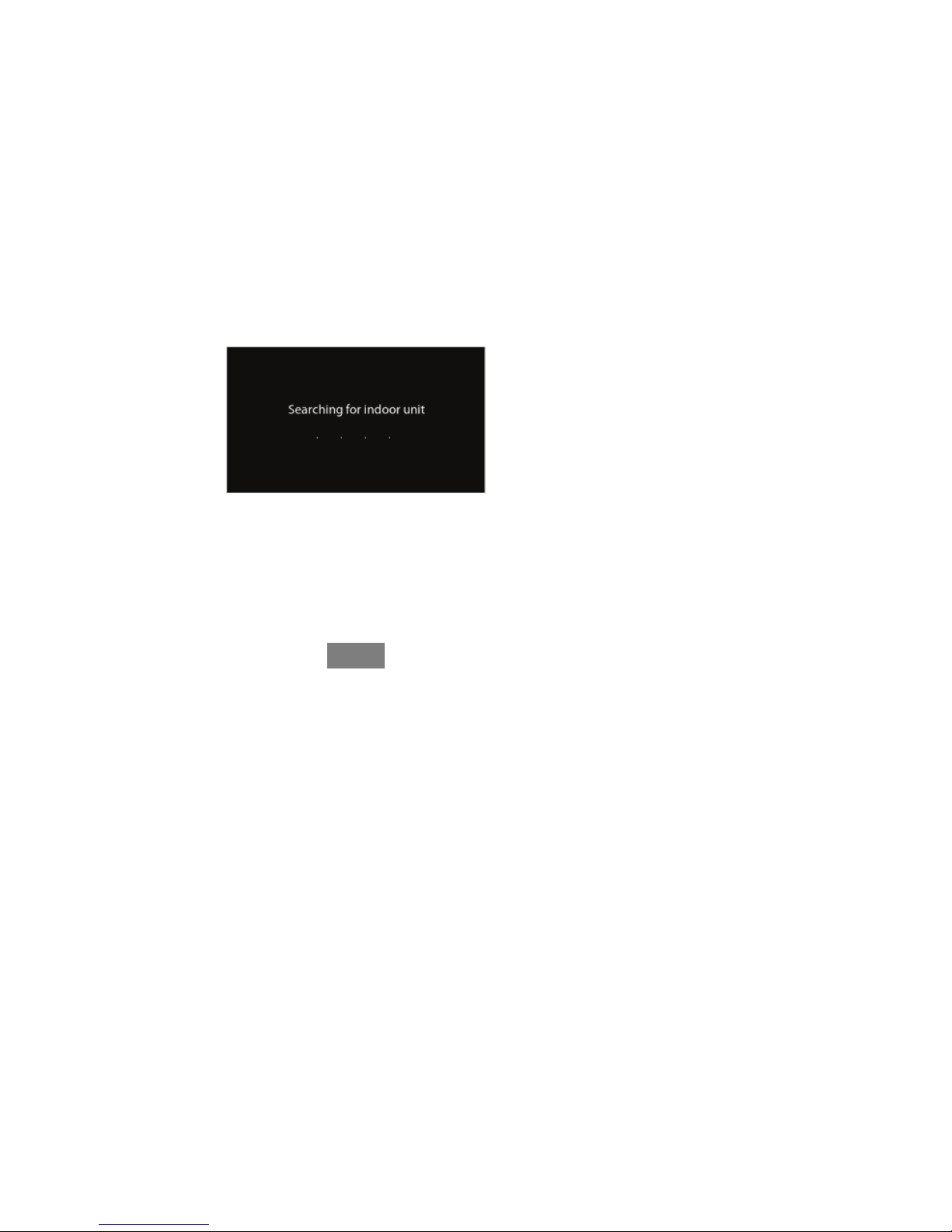
5.1. Searching for Indoor Unit
The Evolutionr Connex Control will light up and begin the commissioning process
by displaying “Searching for indoor unit”. This includes Evolutionr small
packaged products (SPP), with UI Version 8.0 software or later.
A12177
NOTE: If the Evolution--compatible indoor equipment (furnace or fan coil) cannot
be found, the control will display “Indoor unit not found”. This MUST be corrected
before the initial power up sequence can continue. Proceed to the next section,
Searching for outdoor unit. If it is not corrected, the Evolution Connex Control will
go into its DEMO operating mode.
17
A12178
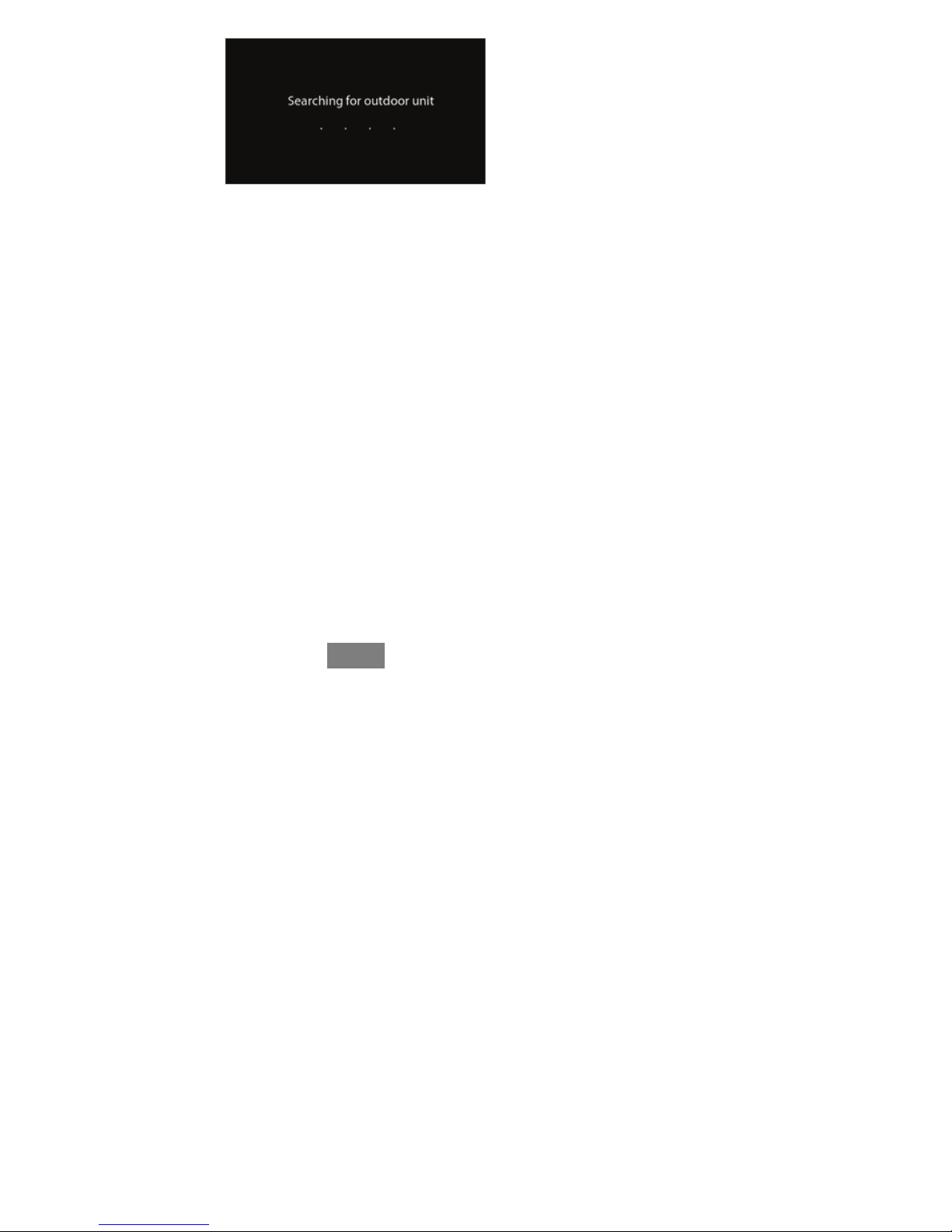
5.2. Searching for Outdoor Unit
The Evolution Connex Control will then proceed to communicate with the outdoor
unit by displaying “Searching for outdoor unit”. This includes Evolutionr small
packaged products (SPP), with UI Version 8.0 software or later.
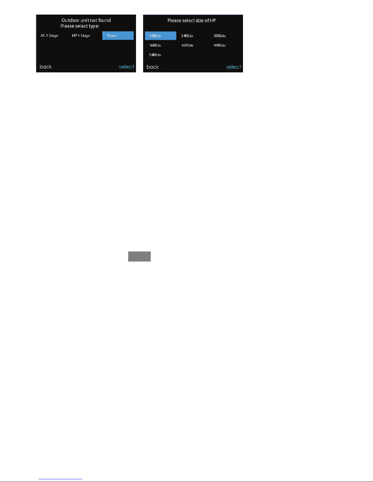
NOTE: If the outdoor unit cannot be found, the control will display “Outdoor unit
not found”.
S Select the appropriate unit installed; then, touch NEXT.
d AC1Stage – 1--stage air conditioner
d *AC2Stage – 2--stage air conditioner
d *HP1Stage – 1--stage heat pump
d *HP2Stage – 2--stage heat pump
d None – No outdoor unit installed
NOTE: For small packaged products (SPP), the selection screen is not needed and
will not appear.
S The installer will first be instructed to select the appropriate size of the outdoor
unit; then, touch SELECT.
*Network Interference Module (NIM) may be required for these selections to be displayed.
18
A13118
5.3. Indoor Evaporator Selection
If a furnace is installed with a variable capacity heat pump or an Evolution V heat
pump, a screen will appear to select the installed indoor evaporator coil. This
selection is used to adequately calculate the refrigerant charge required while in the
heat pump charging screens under the Heat Pump Checkout menu (See Pg. 54).
Select “other” for non--Bryant evaporators.
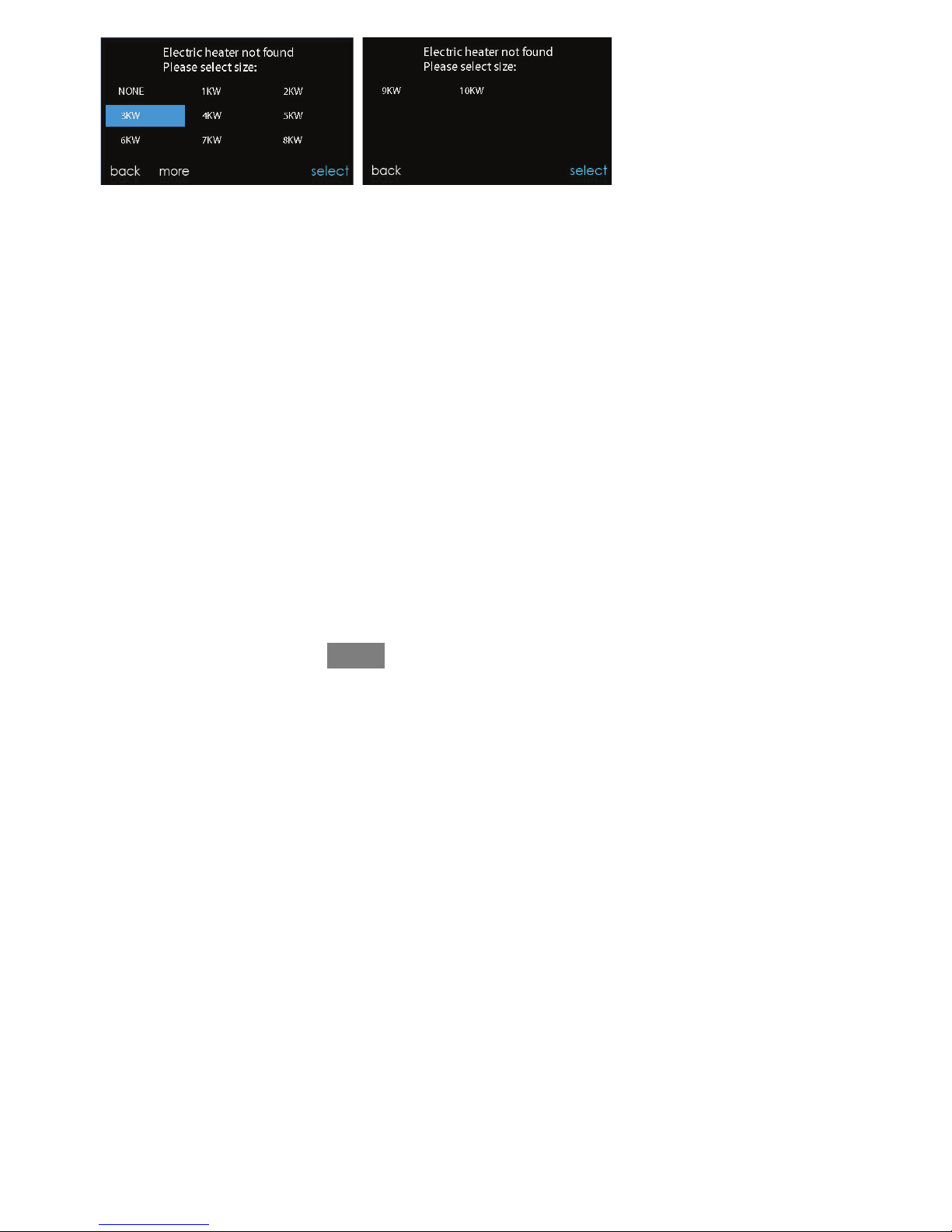
5.4. Electric Heater Selection
If the indoor equipment is a fan coil, the control will display “Searching for heater”
until one is found. If the electric heater is not self--identifying, the select heater
screen will appear. Touch the appropriate heater size; then, touch SELECT.
19
A13119
5.4.1. Hydronic Heat Application
The Evolution Connex Control supports 2 types of Hydronic Heat applications:
1. Hot water coil in combination with an FE fan coil and heat pump, or hot
water coil as sole heat source with an FE fan coil.
2. Non--zoned FE fan coil combined with radiant hot water heat.
In either application, a Hydronic Heat kit should be installed in place of an electric
heater. See FE fan coil Product Data for accessory part number. The system will
self--identify that hydronic heat has been installed during electric heater selection.
The system will treat the hot water coil as either auxiliary heat in a heat pump
application, or the sole heat source. Setup options for Hydronic Heat applications
are described in the setup section of this instruction.
20
A13117
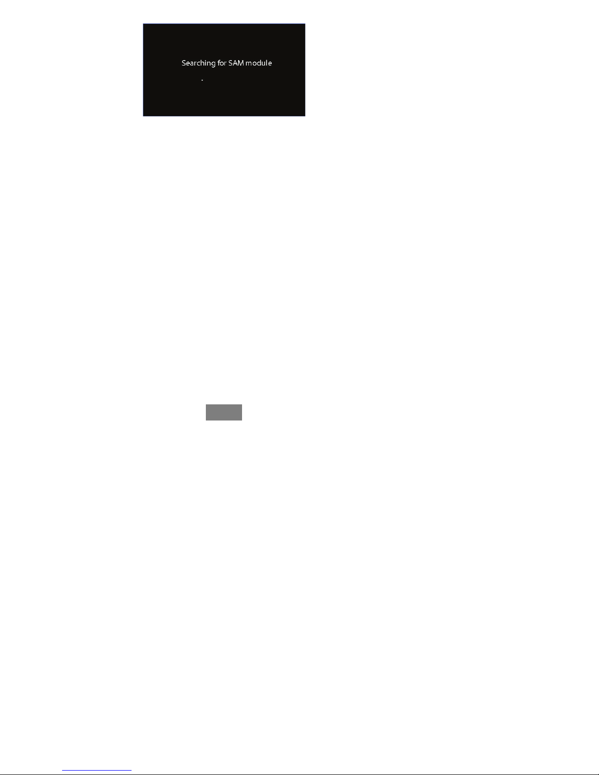
5.5. Searching for SAM Module (If Applicable)
“Searching for SAM Module” will appear on the screen to determine if a System
Access Module, used for home automation only, is connected to the system.
The SYSTXBBSAM01 is not compatible with this control. The compatible modules
are SYSTXBBRCT01 and SYSTXBBRWF01. The SAM is used for home
automation purposes. The Evolution Connex control must have at least Version 8 or
newer to be compatible with the SAM.
NOTE: For more information regarding the SAM Module, reference the latest
version of the application specification entitled “Carrier Communicating HVAC
System” (Version 2 or later), available on HVACpartners.com, or the System
Access Module Installation Instructions.
5.6. Searching for Zones (If Applicable)
This function is not available with the 986T furnace.
“Zoning -- Searching” will appear on the screen to determine if any zones are
present. The screen will show Zone 1, Zone 2, etc. and indicate all zones having
either a Remote Room Sensor, or smart sensors associated with them. If the system
contains smart sensors, they must be assigned a zone number before continuing.
See the Smart Sensor Installation Instructions on how to assign Smart Sensors to
their respective zones. After each zone has been identified, touch NEXT.
 Loading...