

Page 1

SYSTXBBRCT01
EVOLUTIONr SYSTEM
CAT--5 (WIRED) BROADBAND
REMOTE ACCESS MODULE
Installation Instructions
NOTE: Read the entire instruction manual before starting the
installation.
pointSETt U.S. Pat No. 7,415,102
TABLE OF CONTENTS
PAGE
SAFETY CONSIDERATIONS 1.........................
INSTALLATION CONSIDERATIONS 1...................
INTRODUCTION 1...................................
Computer Requirements 1.............................
CAT--5 B--SAM INSTALLATION 2.......................
BEFORE STARTING: 2..............................
Check Equipment and Job Site 2........................
Component Location and Wiring Considerations 2..........
Install Components 2.................................
Connect Evolution Systems 2...........................
Connect Auxiliary Sensor (optional) 2....................
Connect Power Source and Network Cable 2...............
System Start--Up 2...................................
Network Setup 3.....................................
MAC Address and Serial Number 3......................
Self--Test 3.........................................
RS--232 Connector 3.................................
Updating System Profile 3.............................
Local PC Access 3...................................
Account Setup 3.....................................
TROUBLESHOOTING 3...............................
SAFETY CONSIDERATIONS
Improper installation, adjustment, alteration, service, maintenance,
or use can cause explosion, fire, electrical shock, or other
conditions which may cause death, personal injury or property
damage. Consult a qualified installer, service agency or your
distributor or branch for information or assistance. The qualified
installer or agency must use factory--authorized kits or accessories
when modifying this product. Refer to the individual instructions
packaged with the kits or accessories when installing.
Follow all safety codes. Wear safety glasses, protective clothing,
and work gloves. Have a fire extinguisher available. Read these
instructions thoroughly and follow all warnings and cautions
included in literature and attached to the unit. Consult local
building codes and the current edition of the National Electrical
Code (NEC) NFPA 70.
In Canada, refer to the current editions of the Canadian Electrical
Code CSA C22.1.
Recognize safety information. When you see this symbol
the unit and in instructions or manuals, be alert to the potential for
personal injury. Understand the signal words DANGER,
WARNING,andCAUTION. These words are used with the
safety--alert symbol. DANGER identifies the most serious hazards,
which will result in severe personal injury or death. WARNING
signifies hazards, which could result in personal injury or death.
CAUTION is used to identify unsafe practices, which may result
in minor personal injury or product and property damage. NOTE
is used to highlight suggestions which will result in enhanced
installation, reliability, or operation.
on
INSTALLATION CONSIDERATIONS
The CAT--5 Broadband Remote Access Module (CAT--5 B--SAM),
part number SYSTXBBRCT01, is powered with a 24VAC
transformer. A 120VAC supply must be near the mounting
location. Provisions must be made to secure the transformer to the
outlet. The D--wire (24VAC) from the Evolutiont System must
NOT be used to power the Remote Access Module.
This instruction covers the physical installation and start up of the
CAT--5 B--SAM. Use this instruction to guide the actual
installation process after the Evolution System(s) have been
installed. One CAT--5 B--SAM is capable of handling two
Evolution Systems.
INTRODUCTION
The CAT--5 B--SAM connects to a network router and allows
remote connectivity for up to two Evolution Systems within the
same building. The Evolution System owner as well as authorized
dealer can monitor and control the system via the Internet as well
as by telephone. The CAT--5 B--SAM communicates through the
homeowner’s cable or DSL Internet service. Broadband Internet
service with a network router is required. The CAT--5 B--SAM is
not compatible with dial--up Internet service. The CAT--5 B--SAM
can also monitor a dry--contact sensor to provide a warning for the
presence of water in the building, or some otheruse. If the sensor is
active, the Evolution System will not be disabled or shut down.
Computer Requirements
The CAT--5 B--SAM uses a web--based application to control and
monitor the Evolution System. This application will work with any
graphic user interface PC operating system (Microsoft, Apple,
Linux). The web--based application is optimized for use with
Microsoft’s Internet Explorer version 6 and above. Other web
browsers are compatible with some possible screen formatting
issues.
Page 2
CAT--5 B--SAM INSTALLATION
BEFORE STARTING:
S SYSTXBBUID01--B or SYSTXBBUIZ01--B is required
(version 14 software revision or higher).
Check Equipment and Job Site
INSPECT EQUIPMENT -- File claim with shipping company,
prior to installation, if shipment is damaged or incomplete.
Component Location and Wiring Considerations
!
WARNING
ELECTRICAL OPERATION HAZARD
Failure to follow this warning could result in personal injury
or death.
Before installing, modifying, or servicing system, the main
electrical disconnect switch must be in the OFF position and
install a lockout tag. There may be more than 1 power
disconnect switch. Lock out and tag switch with a suitable
warning label.
NOTE: All wiring must comply with national, state, and local
SYSTXBBRCT01
codes.
LOCATING THE UNIT -- CAT--5 B--SAM is approved for
indoor use only and should never be installed with any of its
components exposed to outdoor environmental conditions. The
CAT--5 B--SAM may be installed in any area where the
temperature remains between --4_F/--20_C and 158_F/70_C,
and there is no condensation. The cover must be installed to
prevent damage from other sources. Do not locate where it will be
accessible to children. It should be mounted in the vertical position.
For wiring convenience, the CAT--5 B--SAM can be located
anywhere between the network router and HVAC equipment. The
CAT--5 B--SAM does not need to be located near the HVAC
equipment and can be located near the router, if a long Ethernet
cable run cannot be made.
!
CAUTION
EQUIPMENT DAMAGE HAZARD
Failure to follow this caution may result in equipment
damage.
Do not mount unit on plenum, ductwork, or flush against
furnace.
WIRING CONSIDERATIONS -- Ordinary thermostat wire is ideal
when wiring the CAT--5 B--SAM into the HVAC system (shielded
cable is not necessary). Use 22 gauge or larger for normal wiring.
Lengths over 100 ft / 30 m should use 20 gauge or larger wire.
Network connections will require appropriate network wire -CAT--5e shielded cable is recommended.
Install Components
I N S T A L L C A T -- 5 B -- S A M
The CAT--5 B--SAM is designed so that wires can enter it from
behind, above, or below. Plan wire routing before mounting.
1. Remove cover to access mounting holes.
2. Mount back plate to wall using screws and wall anchors
provided.
3. Level back plate and tighten screws.
!
CAUTION
EQUIPMENT DAMAGE HAZARD
Failure to follow this caution may result in equipment
damage or improper operation.
Improper wiring of the ABC connector will cause the system
to operate improperly. Check to make sure all wiring is
correct before proceeding with installation or turning on of
power.
Connect Evolution Systems
Connect the A, B, and C wires from the Evolution System to
terminals labeled A1, B1, and C1. Connect the second Evolution
System (if present) to the terminals labeled A2, B2 and C2.
ABC bus wiring only requires a three--wire connection; however, it
is good practice to run thermostat cable greater than three wires in
the event of a damaged or broken wire during the installation.
It is recommended that the following color--code be used when
wiring each ABC connector:
A -- Green Data A
B -- Yellow Data B
C -- White 24VAC (Com)
NOTE: The D--wire (red-- 24VAC hot) from the Evolution
System is not connected to the CAT--5 B--SAM. It is not
mandatory that the above color code be used, but each ABC
connector in the system MUST be wired consistently.
Connect Auxiliary Sensor (optional)
The CAT--5 B--SAM will support a dry contact sensor for use with
water detection or some other use as seen fit. Connect one side of
the contacts to connector AUX C (common) and the other side to
connector AUX (input). The sensor input can provide up to 20mA
at 5 volts d.c. If the sensor input is active, it will not shutdown or
affect operation of the HVAC system(s). A pop--up message will
appear on the User Interface indicating the auxiliary sensor is
active. The homeowner will also be notified via email and/or
phone if so chosen on the Internet web interface.
Connect Power Source and Network Cable
Connect a network cable (RJ45 terminated). See Figure 1 for cable
attachment location.
A 24VAC transformer is required to power the CAT--5 B--SAM.
The transformer is available to order through RCD
(SYSTXNNXFM01). Do NOT connect the D--wire (24VAC
hot) from the Evolution System.
The transformer is heavy. Make sure it is secured to the power
outlet with an appropriate screw through the base on the
transformer.
System Start--Up
The User Interface of the Evolution System will automatically find
the CAT--5 B--SAM at power on. It will enter the system
installation screens automatically and will display the Equipment
Summary screen when finished. The Equipment Summary screen
will display REMOTE ACCESS near the bottom.
If REMOTE ACCESS is not displayed on the Equipment
Summary screen, check connections to the ABC wires as well as
ensure the yellow LED is lit on the CAT--5 B--SAM (this ensures
the module has power). The Green LED will be lit next to each
ABC connection if the User Interface has established
communications.
2
Page 3

Network Setup
After the Evolution System has learned the CAT--5 B--SAM, the
homeowner’s network parameters may be entered at the User
Interface. If the homeowner’s network router is setup for DHCP,
then the CAT--5 B--SAM’s network parameters cannot be changed.
Enter the INSTALL/SERVICE menus on the User Interface with a
10 second press of the Advance button. Choose SETUP --> SAM
SETUP. The following screen will appear.
MAC Address and Serial Number
The MAC Address and Serial Number of the CAT--5 B--SAM is
used by the system owner to register their system with Bryant.
Write down the MAC Address and CAT--5 B--SAM serial number
in the home owner’s guide. The serial number can be found on the
CAT--5 B--SAM packaging, at the bottom of the large CAT--5
B--SAM circuit board, or in the User Interface
INSTALL/SERVICE menus under SERVICE-->MODEL/SERIAL
NUMBERS selection. The MAC address can be found on a label
on the wired module.
If the MAC Address is missing or unreadable, it can be found by
entering the INSTALL/SERVICE menus of the User Interface (10
second press of the Advance button). The MAC Address will be
listed on the SETUP--SAM SETUP-->SAM SETUP1 screen.
Self--Test
The purpose of this test is to verify effective 2--way Internet
communication.
Press and hold the TEST switch for at least 5 seconds. A flashing
Yellow LED will indicate the test is in progress. A flashing Yellow
and Green LED means the transmission is complete and the
CAT--5 B--SAM is waiting for a reply. A constant Green LED
means the test has passed. This test should be completed in just a
few seconds.
If the Red LED is lit solid, then the CAT--5 B--SAM failed to send
the message. Ensure that network connectivity is present and that
the homeowner’s Internet service is operating properly.
If the Yellow LED is lit solid, then the CAT--5 B--SAM sent its
message but did not receive a reply. The Bryant server may be
down. Retry at a later time.
Test aborting -- There is no method to abort a test once it is started,
other than to remove power.
The LEDs will maintain their state for 1 hour after the test.
Pressing the Radio Test button momentarily will clear the LEDs.
Pressing the Radio Test button again for five seconds will repeat
the radio test.
RS--232 Connector
An RS--232 port has been provided for connection to home
automation equipment. Consult your homeautomation supplier for
support.
Updating System Profile
The Evolution System will automatically send system information
to Bryant’s computer servers within one hour after the system has
been successfully installed. Access to the system via the Internet or
telephone will not be available until this occurs. The system can be
forced to send its information through the following process if
Internet and telephone access is required immediately. Press and
hold the Radio Test button for 15 seconds. When the button is first
pressed the Red LED will turn on. Five seconds into the press, the
Yellow LED will turn on. Fifteen seconds into the press, the Green
COM1 LED will turn on. Release the button when the Green LED
turns on.
The Red LED will flash when messages are being sent. The Red
and Yellow LEDs will flash when the CAT--5 B--SAM is waiting
for message replies. Upon successful profiling, both Green LEDs
will be lit. If profiling is not successful, the Red LED will be lit
solid.
If the Evolution System ABC wiring is moved from connector 1 to
connector 2 (or vice versa), or Evolution equipment has changed,
the CAT--5 B--SAM must update Bryant’s servers with the new
information. This will happen automatically within one hour, or
can be manually forced with the process described above.
Local PC Access
The Evolution System(s) can be monitored, and the CAT--5
B--SAM setup can be changed, through use of the CAT--5
B--SAM’s embedded web server. From a PC on the same network
as the CAT--5 B--SAM, type the IP address of the CAT--5 B--SAM
in the address field of your web browser.
Account Setup
Setting up your Evolution Remote Access Account requires
Internet access and should take just a few minutes of your time.
Before logging on to the Internet site listed below, be sure to have
the following information available:
1. CAT--5 B--SAM serial number and MAC address.
2. The name and contact information of person you want
the system to contact if maintenance or service is required.
3. The name of the dealer you would like to perform
Routine Maintenance and/or Emergency Service.
4. To setup your Remote Access Account, go to the following Internet address: www.myevolution.bryant.com
5. At the welcome page, look for the text “New Users:
Click Here”.
TROUBLESHOOTING
FAULT INDICATORS -- Under normal operation, the Yellow and
Green LED will be on continuously (solid). If the CAT--5 B--SAM
does not receive communications with the Evolution System, the
green LED will not be on. If there are faults present, the yellow
LED indicator will blink a two--digit status code. The first digit
will blink at a fast rate, the second at a slow rate.
STATUS
CODE
45 Board Failure
62
64 Auxiliary sensor active
66
67
DESCRIPTION RESOLUTION
Replace CAT--5 B--SAM.
Ensure that cable beLoss of communication
with Ethernet device
Ethernet network not
detected
No communication with
server
tween SAM circuit boards
are seated properly.
Replace
Auxiliary sensor terminals
are shorted by external
device.
Make sure network pa-
rameters are correct in
SAM setup screens.
Make sure router is con-
nected to the Internet and
network parameters are
correct.
CAT--5 B--SAM.
SYSTXBBRCT01
3
Page 4
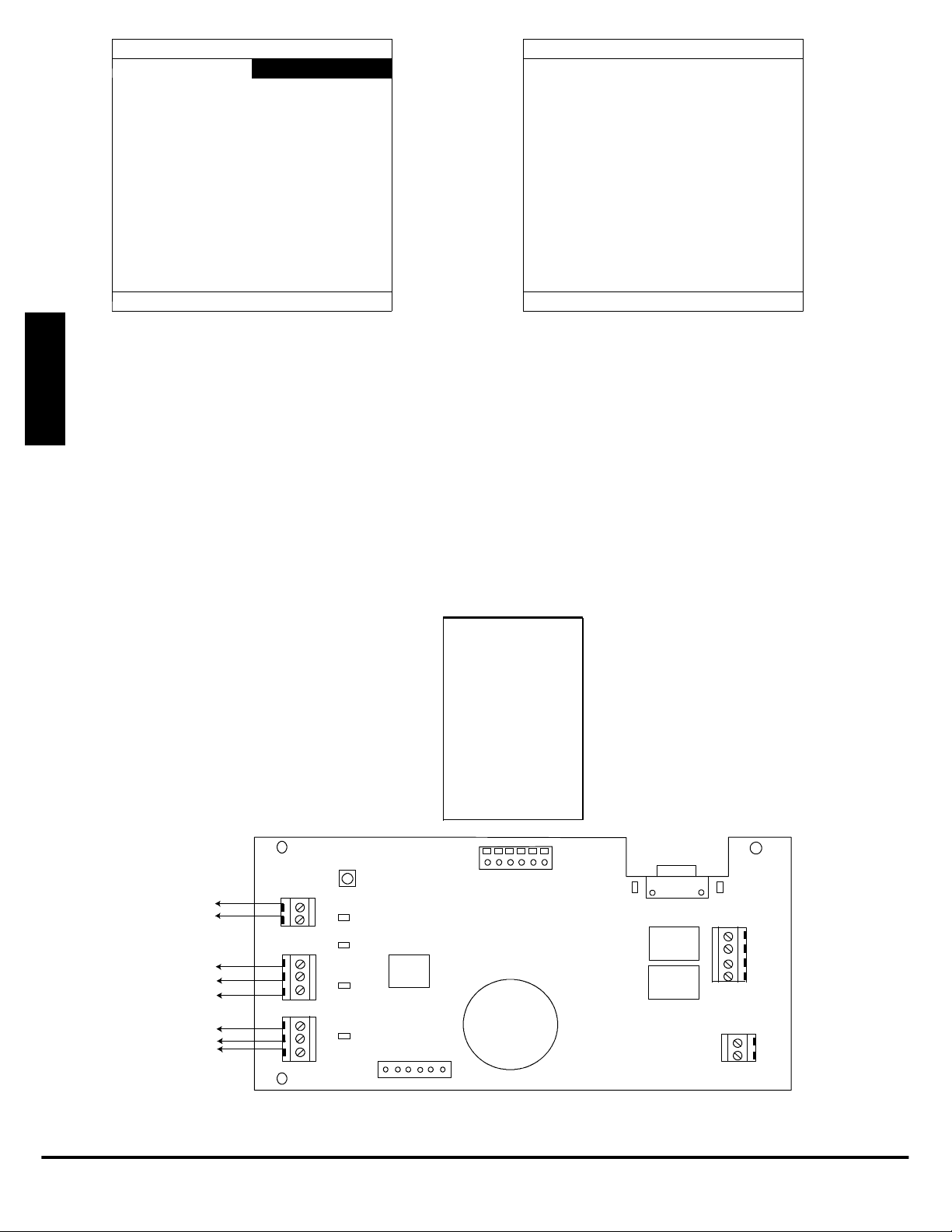
SAM SETUP 1
AUX: AUX SENSOR
IP TYPE: DHCP
IP: 192.168.100.0
MAC ADDR:
00:01:02:03:04:05
SUBNET MASK:
255.255.255.000
SERVER
STATUS: CONNECTED
SAM SETUP 2
DEFAULT GATEWAY:
192.168.001.001
DNS SERVER:
061.010.231.015
PORT: 49152
SERVER
STATUS: CONNECTED
<BACK NEXT >
<BACK NEXT >
AUX: The auxiliary sensor can be renamed to something meaningful, such as WATER or GENERATOR. Use the Temp +/-- buttons to move
between letters, and the Time +/-- button to choose letters.
IP TYPE: Choose DHCP (default) or STATIC for the Internet addressing type.
IP: Shows the current IP address of the CAT--5 B--SAM. If IP TYPE is STATIC then this item can be changed. Use the Temp +/-- buttons to
move between letters, and the Time +/-- button to choose letters. If IP TYPE is DHCP, the IP address cannot change.
MAC ADDR: Shows the MAC Address of the CAT--5 B--SAM’s network module.
SYSTXBBRCT01
SUBNET MASK: If the IP TYPE is STATIC, this can be changed to a different subnet number. Use the Temp +/-- buttons to move between
letters, and the Time +/-- button to choose letters. If IP TYPE is DHCP, the SUBNET MASK cannot be changed.
DEFAULT GATEWAY: If the IP TYPE is STATIC, this can be changed to point to a different gateway. Use the Temp +/-- buttons to move
between letters, and the Time +/-- button to choose letters. If IP TYPE is DHCP, the DEFAULT GATEWAY cannot be changed.
DNS SERVER: If the IP TYPE is STATIC, this can be changed to point to a different DNS server. Use the Temp +/-- buttons to move
between letters, and the Time +/-- button to choose letters. If IP TYPE is DHCP, the DNS SERVER cannot be changed.
PORT: This can be changed to use a different port through the homeowner’s network. The default is port 49152.
SERVER STATUS: Shows status of the CAT--5 B--SAM connection to Bryant’s servers. If the screen shows NON CONNECTED, please
check network settings or network cable.
Ethernet
Module
Home
Automation
Connection
(RS- 232)
AUXILIARY
SENSOR
ABC TO
SYSTEM 1
ABC TO
SYSTEM 2
WLS
WLSC
A1
B1
C1
A2
B2
C2
TEST
STATUS
COMM1
COMM2
SERIAL NUMBER
Fig. 1 -- CAT--5 Module Control Board
E2012 Bryant Heating & Cooling Systems D 7310 W. Morris St. D Indianapolis, IN 46231 Printed in U.S.A. Edition Date: 02/12
Manufacturer reserves the right to discontinue, or change at any time, specifications or designs without notice and without incurring obligations.
4
24VAC
A06512
Catalog No. IIBBRCT---02
Replaces: IIBBRCT--- 01
 Loading...