

Bryant EVOLUTION 986TA, EVOLUTION 986TA030040, EVOLUTION 986TA042060, EVOLUTION 986TA048080, EVOLUTION 986TA048100 Product Data
...
986TA
EVOLUTIONR TWO--STAGE
4--WAY MULTIPOISE, VARIABLE SPEED
CONDENSING GAS FURNACE, SERIES A
Product Data
A11264
The 986TA Multipoise Variable--Speed Condensing Gas Furnace is
features the two--stage EvolutionR System. The Perfect HeatR
technology two--stage gas valve is at the heart of the comfort
provided by this furnace, along with the variable--speed ECM
blower motor, and two--speed inducer motor. With an Annual Fuel
Utilization Efficiency (AFUE) up to 96.5%, the Evolution
two--stage gas furnace provides exceptional savings as well when
compared to standard gas furnaces. This Evolution Gas Furnace
also features 4--way multipoise installation flexibility, and is
available in five model sizes. The 986TA can be vented for direct
vent/two--pipe, ventilated combustion air, or single--pipe
applications. A Bryant Evolution Control and Evolution Air
Conditioner or Heat Pump, can be used to form a complete
Evolution System. All units meet California Air Quality
Management District emission requirements. All sizes are design
certified in Canada.
STANDARD FEATURES
S EvolutionR System; compatible with single--zone Evolution
systems
S Evolution Features—match with the Evolution Control for
Evolution System benefits
S Quiet operation. Comparefor yourself at HVACpartners.com
S Ideal height 35” (889 mm) cabinet: short enough for taller coils,
but still allows enough room for service
S Silicon Nitride Perfect Light™ Hot Surface Igniter
S SmartEvap™ technology helps control humidity levels in the
home when used with a compatible humidity control system
S FanOn Plus
from a compatible thermostat
S External Media Filter Cabinet included
S 4--way multipoise design for upflow, downflow or horizontal
installations, with unique vent elbow and optional through-the--cabinet downflow venting capability
S Variable--Speed blower motor, two--speed inducer motor, and
two--stage gas valve
S Self--diagnostics and extended diagnostic data through the
Advanced Product Monitor (APM) accessory or Evolution User
Interface
S Adjustable blower speed for cooling, continuous fan, and
dehumidification
S Aluminized--steel primary heat exchanger
S Stainless--steel condensing secondary heat exchanger
S Propane convertible (See Accessory list)
S Factory--configured ready for upflow applications
S Fully--insulated casing including blower section
S Convenient Electronic Air Cleaner and Humidifier connections
S Direct--vent/sealed combustion, single--pipe venting or
ventilated combustion air
S Installation flexibility: sidewall or vertical vent
S Residential installations may be eligible for consumer financing
through the Retail Credit Program
™ technology allows control of continuous fan speed
LIMITED WARRANTY*
S 10 year partsand lifetime heat exchanger limited warranty to the
original purchaser upon timely registration.
S Limited warranty period is five years for parts and twenty years
for the heat exchanger if not registered within 90 daysof
installation.{
* For owner occupied, residential applications.
{Jurisdictions where warranty benefits cannot be conditioned on registra-
tion will receive registered limited warranty benefits.
CERTIFIED
Use of the AHRI Certified TM Mark indicates a
manufacturer’s participation in the program. For
verification of certification for individual products,
go to www.ahridirectory.org.
1
Always Ask For
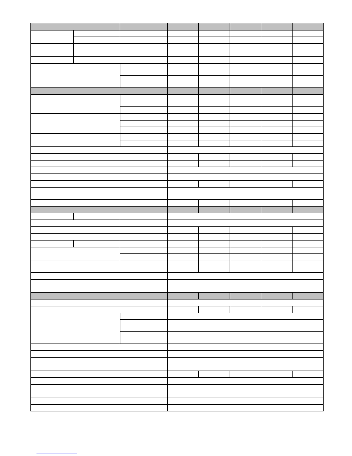
SPECIFICATIONS
Heating Capacity and Efficiency 030040 042060 048080 048100 066120
Input
Output
Efficiency AFUE % (ICS) 96.5 96.3 96.2 96.5 96.5
Certified Temperature
Rise Range ºF (ºC)
Airflow Capacity and Blower Data 030040 042060 048080 048100 066120
Certified External Static
Pressure (in. w.c.)
Airflow Delivery
@RatedESP(CFM)
Cooling Capacity (tons)
@ 400, 350 CFM/ton
Direct-Drive Motor Type Electronically Commutated Motor (ECM)
Direct-Drive Motor HP 1/2 3/4 3/4 1 1
Motor Full Load Amps 6.8 8.4 8.4 10.9 10.9
RPM Range 600 - 1200
Speed Selections Variable (PWM)
Blower Wheel Dia x Width in. 11x7 11x8 11x8 11x10 11 x 11
Air Filtration System
Filter Used for Certified Watt Data
Electrical Data 030040 042060 048080 048100 066120
Input Voltage Volts-Hertz-Phase 115-60-1
Operating Voltage Range Min-Max 104-127
Maximum Input Amps Amps 8.2 9.8 9.8 12.3 12.3
Unit Ampacity Amps 11.0 13.0 13.0 16.1 16.1
Minimum Wire Size AWG 14 14 14 12 12
Maximum Wire Length
@ Minimum Wire Size
Maximum Fuse/Ckt Bkr
(Time-Delay Type Recommended)
Transformer Capacity (24vac output) 40 VA
External Control Power
Available
Controls 030040 042060 048080 048100 066120
Gas Connection Size 1/2” - NPT
Burners (Monoport) 2 3 4 5 6
Gas Valve (Redundant)
Gas Conversion Kit - N atural to Propane KGANP5201VSP
Gas Conversion Kit - Propane to Natural KGAPN4401VSP
Manufactured (Mobile) Home Kit not approved for MH use
Ignition Device Silicon Nitride
Limit Control 165 180 170 160 160
Heating Blower Control (Heating Off-Delay) Adjustable: 90, 120, 150, 180 seconds
Cooling Blower Control (Time Delay Relay) 90 seconds
Communication System Evolution (non-zoning)
Thermostat Connections W2,Y1,DHUM,G,COM24V,W/W1,Y/Y2,R
Accessory Connections EAC (115vac); HUM (24vac); 1-stg AC (via Y/Y2)
High Heat (BTUH) 40,000 60,000 80,000 100,000 120,000
Low Heat (BTUH) 26,000 39,000 52,000 65,000 78,000
High Heat (BTUH) 39,000 58,000 78,000 98,000 117,000
Low Heat (BTUH) 25,000 38,000 50,000 63,000 76,000
High Heat
Low Heat
Heating 0.10 0.12 0.15 0.20 0.20
Cooling 0.5 0.5 0.5 0.5 0.5
High Heat 815 1135 1510 2035 2375
Low Heat 660 860 860 1530 1675
Cooling 905 1475 1610 1805 2115
400 CFM/ton 2 3.5 4 4.5 5
350 CFM/ton 2.5 4 4.5 5 6
Feet 33 28 28 35 35
(M) (10.1) (8.5) (8.5) (10.7) (10.7)
Amps 15 15 15 20 20
Heating 24.3 VA
Cooling 34.6 VA
Manufacturer White Rogers™
Minimum Inlet Gas
pressure (in. W.C.)
Maximum Inlet Gas
pressure (in. W.C.)
40 - 70
(21-38)
30 - 60
(17-33)
KGAWF1606UFR KGAWF1306UFR KGAWF1406UFR KGAWF1506UFR KGAWF1506UFR
35 - 65
(19-36)
30 - 60
(17-33)
Factory Supplied Media Cabinet
40 - 70
(21-38)
30 - 60
(17-33)
FieldSuppliedFilter
4.5
13.6
45 - 75
(25-41)
30 - 60
(17-33)
45 - 75
(25-41)
30 - 60
(17-33)
2
1 - 2
Family/Tier
98
91 - Legacy
92 - Preferred
98 - Evolution
3
Base Eff.
6
0 --- 90 AFUE
3 --- 93 AFUE
5 --- 95 AFUE
6 --- 96 AFUE
7 --- 97 AFUE
4
Htg. Stages
T
S - Single Stage
T - Two Stage
M - Modulating
MODEL NUMBER NOMENCLATURE
5
Major Series
A
Major Series
6 - 7
Clg. Cap.
30
24 - 800 CFM
30 - 1000 CFM
36 - 1200 CFM
42 - 1400 CFM
48 - 1600 CFM
54 - 1800 CFM
60 - 2000 CFM
66 - 2200 CFM
(@ 0.5” ESP)
Not all familes have these models.
8 - 10
Htg. Cap.
040
040=40,000 BTU
060=60,000 BTU
080=80,000 BTU
100=100,000 BTU
120=120,000 BTU
11
Motor
V
S - Standard
E - Energy Efficient
V - Variable Speed
14 - 14.2”
17 - 17.5”
21 - 21.0”
24 - 24.5”
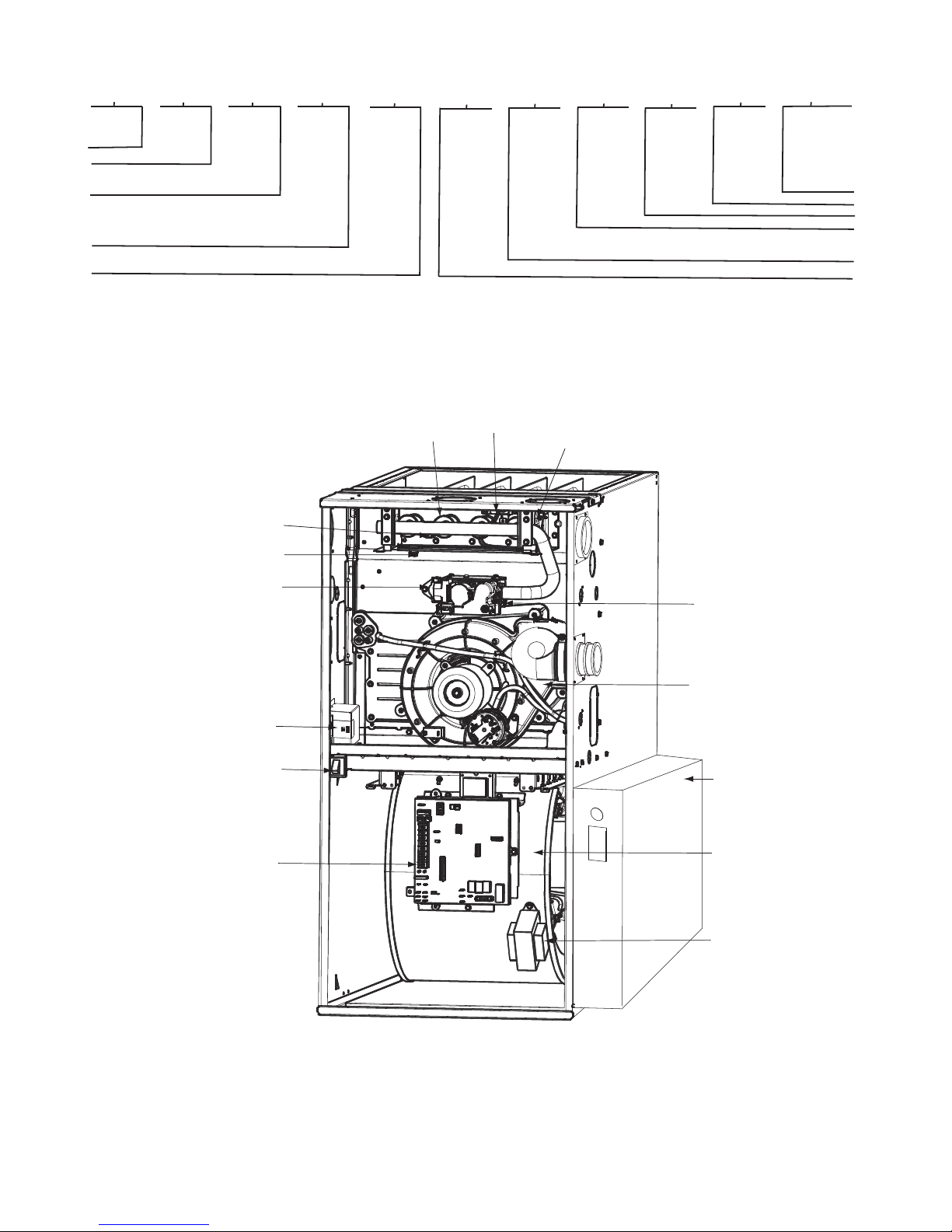
FURNACE COMPONENTS
HOT SURFACE
GAS BURNER
IGNITER
MANUAL RESET
ROLLOUT SWITCH
12 - 13
Width
14
Voltage
Voltage
14
A
15
Features
--
L - Low NOx
16
Minor Series
A
A11163
FLAME
SENSOR
MANUAL RESET
ROLLOUT SWITCH
GAS VALVE
OPERATING INSTRUCTIONS
NOT SHOWN (LOCATED ON
MAIN FURNACE DOOR, SEE
OPERATING INSTRUCTIONS
INSIDE DOOR FIGURE).
ELECTRICAL JUNCTION
BOX (IF REQUIRED,
LOCATION MAY VARY)
BLOWER DOOR
SAFETY SWITCH
FURNACE
CONTROL
BOARD
MAIN LIMIT SWITCH
(BEHIND GAS VALVE)
INDUCER MOTOR
ASSEMBLY
MEDIA CABINET
BLOWER AND
MOTOR
CAPACITOR/
POWER CHOKE
(IF USED)
RATING PLATE NOT SHOWN
(LOCATED ON BLOWER DOOR)
REPRESENTATIVE DRAWING ONLY, SOME MODELS MAY VARY IN APPEARANCE.
A11408
3
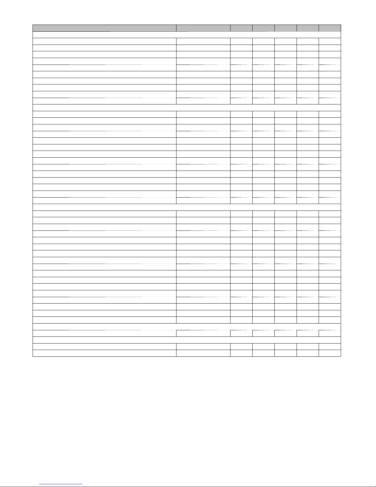
ACCESSORIES
DESCRIPTION PAR T NUMBE R 10040 42060 48080 48100 66120
Venting, Drainage and Installation
Vent Kit - Through the Cabinet KGADC0101BVC X X X X X
Vent Terminal - Concentric - 2” (51 mm) KGAVT0701CVT X X X X N/A
Vent Terminal - Concentric - 3” (76 mm) KGAVT0801CVT N/A X X X X
Vent Terminal Bracket - 2” (51 mm) KGAVT0101BRA X X X X N/A
Vent Terminal Bracket - 3” (76 mm) KGAVT0201BRA N/A X X X X
CPVC to PVC Drain Adapters - 1/2” CPVC to 3/4” PVC KGAAD0110PVC X X X X X
Horizontal Trap Grommet - Direct Vent KGACK0101HCK X X X X X
Freeze Protect Kit - Heat Patch for Drain Trap KGAHT0201CFP X X X X X
Freeze Protect Kit - Heat Tape KGAHT0101CFP X X X X X
Furnace Base Kit for Combustible Floors KGASB0201ALL X X X X X
Gas Conversion
GasCnvKit-NattoLP;Var-spdProducts KGANP5201VSP X X X X X
Gas Cnv Kit - LP to Nat; Var-spd Products KGAPN4401VSP X X X X X
GasOrificeKit-#42(NatGas) KGAHA0150N42 X X X X X
GasOrificeKit-#43(NatGas) KGAHA0250N43 X X X X X
GasOrificeKit-#44(NatGas) KGAHA0350N44 X X X X X
GasOrificeKit-#45(NatGas) KGAHA0450N45 X X X X X
GasOrificeKit-#46(NatGas) KGAHA0550N46 X X X X X
GasOrificeKit-#47(NatGas) KGAHA1550N47 X X X X X
GasOrificeKit-#48(NatGas) KGAHA1650N48 X X X X X
Gas Orifice Kit - #54 (LP) KGAHA0650P54 X X X X X
Gas Orifice Kit - #55 (LP) KGAHA0750P55 X X X X X
Gas Orifice Kit - #56 (LP) KGAHA0850P56 X X X X X
Gas Orifice Kit - 1.25mm (LP) KGAHA5750125 X X X X X
Gas Orifice Kit - 1.30mm (LP) KGAHA5750130 X X X X X
Indoor Air Quality
Bryant Perfect Air Purifier - 16x25 (406x635 mm) GAPAAXBB1625-A08 X X X X X
Bryant Perfect Air Purifier - 20x25 (508x635 mm) GAPAAXBB2025-A08 X X X X X
Bryant Perfect Air Purifier Repl. Filter- 16x25 (406x635 mm) GAPABBCAR1625-A05 X X X X X
Bryant Perfect Air Purifier Repl. Filter- 20x25 GAPABBCAR1625-A05 X X X X X
EZ Flex Cabinet 16” (406 mm) EZXCABBB1016-A20 X X X X X
EZ Flex Cabinet 20” (508 mm) EZXCABBB1020-A20 X X X X X
Cartridge Media Filter - 16” (406 mm) FILXXCAR0016 X X X X X
Cartridge Media Filter - 20” (508 mm) FILXXCAR0020 X X X X X
Cartridge Media Filter - 24” (610 mm) FILXXCAR0024 N/A X X X X
EZ-Flex Filter - 16” (406 mm) EXPXXFIL0016 X X X X X
EZ-Flex Filter - 20” (508 mm) EXPXXFIL0020 X X X X X
EZ-Flex Filter - 24” 610 mm) EXPXXFIL0024 N/A X X X X
EZ-Flex Filter with End Caps - 16” (406 mm) EXPXXUNV0016 X X X X X
EZ-Flex Filter with End Caps - 20” (508 mm) EXPXXUNV0020 X X X X X
EZ-Flex Filter with End Caps - 24” (610 mm) EXPXXUNV0024 N/A X X X X
Filter Pack (6 pack) - Washable - 16x25x1 (406x635x25 mm) KGAWF1306UFR X X X X X
Filter Pack (6 pack) - Washable - 24x25x1 (610x635x25 mm) KGAWF1506UFR N/A X X X X
Controls
Evolution™ Control User Interface SYSTXBBUID01-D X X X X X
Service Tools
Advanced Product Monitor - APM KGASD0301APM X X X X X
ECM Motor Simulator Kit KGASD0301FMS X X X X X
X = Used with this model furnace
N/A = Not used with this model furnace
4
INPUT
BTUH
40000
INPUT
BTUH
AIR DELIVERY -- CFM (BOTTOM RETURN WITH FILTER)
(SW1-5 and SW4-3 set to OFF, except as indicated. See Notes 1 and 2.)
Cooling Switch Settings External Static Pressure (E.S.P.)
SW2-3 SW2-2 SW2-1 0.1 0.2 0.3 0.4 0.5 0.6 0.7 0.8 0.9 1.0
OFF OFF OFF 1125 1080 1020 970 905 855 805 755 700 635
OFF OFF ON 615 555 510 475 440 395 355 270 230 note 7
OFF ON OFF 785 740 695 665 630 590 565 520 485 450
OFF ON ON 990 950 910 875 850 815 770 720 670 615
ON OFF OFF 1125 1080 1020 970 905 855 805 755 700 635
ON OFF ON 1125 1080 1020 970 905 855 805 755 700 635
ON ON OFF 1125 1080 1020 970 905 855 805 755 700 635
ON ON ON 1125 1080 1020 970 905 855 805 755 700 635
Maximum Cooling Airflow
High Heat Airflow
Low Heat Airflow
Cooling Switch Settings External Static Pressure (E.S.P.)
SW2-3 SW2-2 SW2-1 0.1 0.2 0.3 0.4 0.5 0.6 0.7 0.8 0.9 1.0
OFF OFF OFF 1330 1295 1260 1220 1190 1150 1110 1075 1045 1005
OFF OFF ON 725 660 600 520 435
2
1125 1080 1020 970 905 855 805 755 700 635
3
3
815 770 725 695 660 625 595 550 510 475
660 605 560 530 495 450 415 340 300 note 7
60000
INPUT
BTUH
80000
OFF ON OFF 780 725 660 615 540
OFF ON ON 975 925 875 835 785 750 690 655 610 570
ON OFF OFF 1160 1120 1090 1045 1010 970 920 885 840 800
ON OFF ON 1330 1295 1260 1220 1190 1150 1110 1075 1045 1005
ON ON OFF 1705 1650 1595 1545 1475 1415 1340 1275 1200 1105
ON ON ON 1705 1650 1595 1545 1475 1415 1340 1275 1200 1105
Maximum Cooling Airflow
High Heat Airflow
Low Heat Airflow
2
1705 1650 1595 1545 1475 1415 1340 1275 1200 1105
3
3
1145 1105 1075 1030 995 955 905 870 825 785
870 820 760 720 655 620 560 525 470 435
Cooling Switch Settings External Static Pressure (E.S.P.)
SW2-3 SW2-2 SW2-1 0.1 0.2 0.3 0.4 0.5 0.6 0.7 0.8 0.9 1.0
OFF OFF OFF 1805 1765 1720 1665 1610 1540 1475 1400 1315 1235
OFF OFF ON 775 635 455 230 note 7
OFF ON OFF 840 740 675 625 555
OFF ON ON 995 955 910 860 815 770 720 660 620 585
ON OFF OFF 1175 1140 1090 1060 1025 980 940 905 855 815
ON OFF ON 1325 1280 1245 1210 1180 1140 1105 1070 1025 990
ON ON OFF 1545 1515 1480 1445 1410 1380 1350 1315 1245 1175
ON ON ON 1805 1765 1720 1665 1610 1540 1475 1400 1315 1235
Maximum Cooling Airflow
High Heat Airflow
Low Heat Airflow
2
3
3
1805 1765 1720 1665 1610 1540 1475 1400 1315 1235
1520 1490 1455 1420 1385 1355 1320 1285 1220 1155
1180 1145 1095 1065 1030 985 945 910 860 820
5
 Loading...