

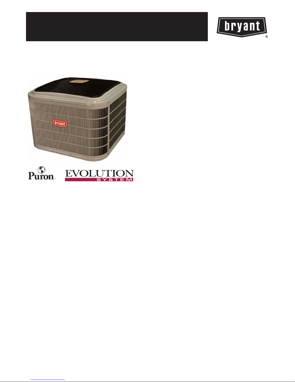
186B
EVOLUTIONR16 AIR CONDITIONER
WITH PURONr REFRIGERANT
1--1/2 TO 5 TONS
Product Data
®
the environmentally sound refrigerant
Bryant’s Air Conditioners with Puronr refrigerant provide a
collection of features unmatched by any other family of
equipment. The 186B has been designed utilizing Bryant’s Puron
refrigerant. The environmentally sound refrigerant allows you to
make a responsible decision in the protection of the earth’s ozone
layer.
This product has been designed and manufactured to meet
Energy Starr criteria for energy efficiency when matched with
appropriate coil components. Refer to the combination ratings in
the Product Data for system combinations that meet Energy Starr
guidelines.
NOTE: Ratings contained in this document are subject to
change at any time. Always refer to the AHRI directory
(www.ahridirectory.org) for the most up--to--date ratings
information.
INDUSTRY LEADING
FEATURES / BENEFITS
Efficiency
14 -- 16 SEER / 11.0-- 13.5 EER
S
S Microtube Technologyt refrigeration system
S Indoor air quality accessories available
Sound
Sound level as low as 68 dBA
S
S Compressor sound blanket standard
Comfort
System supports Evolution Control or standard
S
thermostat controls
Reliability
Puronr refrigerant -- environmentally sound, won’t
S
deplete the ozone layer and low lifetime servce cost.
S Scroll compressor
S Internal pressure relief valve
S Internal thermal overload
S Filter drier
S High and low pressure switches
S Balanced refrigeration system for maximum reliability
Durability
DuraGuard Plust protection package:
S Solid, durable sheet metal construction
S Louvered coil guard
S Baked--on, complete outer coverage, powder paint
Applications
Long--line -- up to 250 feet (76.20 m) total equivalent
S
length, up to 200 feet (60.96 m) condenser above
evaporator, or up to 80 ft. (24.38 m) evaporator above
condenser (See Longline Guide for more information.)
S Low ambient (down to --20_F/--28.9_C)) with
accessory kit
MODEL NUMBER NOMENCLATURE
1234 5 678910111214
NNNAA/NNNNNA/NA/NNA
186B N A018000A
Product
Famil y
1=AC 8=
the environmentally sound refrigerant
186B
Tier SEER Major Se-
Evolution
Series
6=16
SEER
Nominal
B=Puron N=
Use of the AHRI Certified
TM Mark indicates a
manufacturer’s
participation in the
program For verification
of certification for individual
products, go to
www.ahridirectory.org.
ries
Voltage Variation s Coolin g Capacity Open Open Open Minor
208--- 230--- 1
A=
Standard
0=Not
Defined0=Not
Defined
This product h as been designed and manuf actured to
meet Energy Star ® criteria for energy efficiency when
matched wit h appropriate coil components. However,
proper refri gerant c harge and proper air f low ar e crit ical
to achieve r ated capacity and efficiency. Installation of
this product should follow all manufacturing refrigerant
charging and air flow instructions. Failure to confirm
proper charge and air flow may reduce energy
efficiency and shorten equipment life.
0=
Not
Defined
STANDARD FEATURES
Feature 18 24 30 36 42 48 60 61
Puron Refrigerant X X X X X X X X
Maximum SEER * 16.0 16.0 16.5 16.5 16.0 16.0 16.0 16.0
Scroll Compressor X X X X X X X X
FieldInstalledFilterDrier X X X X X X X X
Fron t Seatin g Se rvice Valves X X X X X X X X
Internal Pressure Relief Valve X X X X X X X X
Internal Thermal Overload X X X X X X X X
Long Line capability X X X X X X X X
Low Ambient capability with Kit X X X X X X X X
High Pressure Switch X X X X X X X X
Low Pressure Switch X X X X X X X X
Compressor Sound Blanket X X X X X X X X
Louvered Coil Guard X X X X X X X X
*Based on tested combinations
X=Standard
Series
A=
Original
Series
UNIT SIZE SERIES 018--- A 024--- A 030--- A 036- -- A 042--- A 048 --- A 060--- A 061 --- A
Operating Weight lb (Kg)
Shipping Weight lb (Kg)
Compressor Type Scroll
REFRIGERANT R---410A
Control TXV (R --- 410A Hard Shu toff)
Charge lb (Kg) 5.25 (2.38) 6.00 (2.72) 6.81(3.09) 7.00 (3.18) 8.62 (3.91) 13.00 (5.9)
COND FAN Propeller Type, Direct Drive
Air Discharge Vertical
Air Qty (CFM) 2233 2614 2614 3223 3810 4046 4046 4046
Motor HP 1/12 1/10 1/10 1/12 1/5 1/4 1/4 1/4
Motor RPM 800 800 800 800 800 800 800 800
COND COIL
Face Area (Sq ft) 15.07 15.07 17.22 17.58 25.12 25.12 30.14 30.14
Fins per In. 25 25 25 25 25 20 20 20
Rows 1 1 1 1 1 2 2 2
Circuits 3 4 4 4 6 7 8 8
VALVECONNECT.(In.ID)
Vapor 3/4 3/4 3/4 7/8 7/8 7/8 7/8 7/8
Liquid 3/8 3/8 3/8 3/8 3/8 3/8 3/8 3/8
REFRIGERANT TUBES (In. OD)
Rated Vapor* 3/4 7/8 1 --- 1 / 8
Max L iquid Line 3/8”
*Units are rated with 25 ft (7.6 m) of lineset length. See Vapor Line Sizing and Cooling Capacity Loss table when using other sizes and lengths of lineset.
NOTE: See unit Installation Instruction f or proper installation.
175.5
(79.6)
212.5
(96.4)
PHYSICAL DATA
176
(79.8)
211.5
(95.9)
186.5
(84.6)
222.5
(100.9)
200
(90.7)
243
(110.2)
2
253
(114.8)
297
(134.7)
295
(113.8)
340
(154.2)
327
(148.3)
373.5
(169.4)
14.50
(6.58)
326
(147.9)
373
(169.2)
14.50
(6.58)
REFRIGERANT PIPING LENGTH LIMITATIONS
Liquid Line Sizing and Maximum Total Equivalent Lengths
The maximum allowable length of a residential split system depends on the liquid line diameter and vertical separation between indoor and
outdoor units.
See Table below for liquid line sizing and maximum lengths :
Maximum Total Equivalent Length
Outdoor Unit BELOW Indoor Unit
Liquid
Size
018
AC with
Puron
024
AC with
Puron
030
AC with
Puron
036
AC with
Puron
042
AC with
Puron
048
AC with
Puron
060, 061
AC with
Puron
* Maximum actual length not to exceed 200 ft (61 m)
{ Total equivalent length accounts for losses due to elbows or fitting. See the Long Line Guideline for details.
--- --- = o u t s i d e a c c e p t a b l e r a n g e
Liquid Line
Connection
3/8
3/8
3/8
3/8
3/8
3/8 3/8 250* 250* 250* 250* 250* 250* 230 160 --- ---
3/8 3/8 250* 250* 250* 225* 190 150 110 --- --- --- ---
Line
Diam.
w/ TXV
1/4 150 150 125 100 100 75 --- --- --- --- --- ---
5/16 250* 250* 250* 250* 250* 250* 250* 225* 150
3/8 250* 250* 250* 250* 250* 250* 250* 250* 250*
1/4 75 75 75 50 50 --- --- --- --- --- --- --- ---
5/16 250* 250* 250* 250* 250* 225* 175 125 100
3/8 250* 250* 250* 250* 250* 250* 250* 250* 250*
1/4 30 --- --- --- --- --- --- --- --- --- --- --- --- --- --- --- ---
5/16 175 225* 200 175 125 100 75 --- --- --- ---
3/8 250* 250* 250* 250* 250* 250* 250* 250* 250*
5/16 175 150 150 100 100 100 75 --- --- --- ---
3//8 250* 250* 250* 250* 250* 250* 250* 250* 250*
5/16 125 100 100 75 75 50 --- --- --- --- --- ---
3/8 250* 250* 250* 250* 250* 250* 250* 250* 150
(0---1.5)
AC with Puron Refrigerant Maximum Total Equivalent Length{: Outdoor unit BELOW Indoor
0 --- 5
6 --- 1 0
(1.8---3.0)
11---20
(3.4---6.1)
{
for Cooling Only Systems with Puronr Refrigerant:
Vertical Separation ft (m)
21---30
(6.4---9.1)
31---40
(9.4---12.2)
41---50
(12.5---15.2)
51---60
(15.5---18.3)
61---70
(18.6---21.3)
71---80
(21.6---24.4)
186B
Maximum Total Equivalent Length
Outdoor Unit ABOVE Indoor Unit
Liquid
Size
018
AC with
Puron
024
AC with
Puron
030
AC with
Puron
036
AC with
Puron
042
AC with
Puron
048
AC with
Puron
060, 061
AC with
Puron
* Maximum actual length not to exceed 200 ft (61 m)
{ Total equivalent length accounts for losses due to elbows or fitting. See the Long Line Guideline for details.
--- --- = o u t s i d e a c c e p t a b l e r a n g e
Liquid Line
Connection
3/8
3/8
3/8
3/8
3/8
3/8 3/8 250* 250* 250* 250* 250* 250* 250* 250*
3/8 3/8 250* 250* 250* 250* 250* 250* 250* 250*
Line
Diam.
w/ TXV
1/4 175 250* 250* 250* 250* 250* 250* 250*
5/16 250* 250* 250* 250* 250* 250* 250* 250*
3/8 250* 250* 250* 250* 250* 250* 250* 250*
1/4 100 125 175 200 225* 250* 250* 250*
5/16 250* 250* 250* 250* 250* 250* 250* 250*
3/8 250* 250* 250* 250* 250* 250* 250* 250*
1/4 30 --- --- --- --- --- --- --- --- --- --- --- --- --- ---
5/16 250* 250* 250* 250* 250* 250* 250* 250*
3/8 250* 250* 250* 250* 250* 250* 250* 250*
5/16 225* 250* 250* 250* 250* 250* 250* 250*
3/8 250* 250* 250* 250* 250* 250* 250* 250*
5/16 175 200 250* 250* 250* 250* 250* 250*
3/8 250* 250* 250* 250* 250* 250* 250* 250*
AC with Puron Refrigerant Maximum Total Equivalent Length{: Outdoor unit ABOVE Indoor
25
(7.6)
26---50
(7.9---15.2)
51---75
(15.5---22.9)
Vertical Separation ft (m)
76---100
(23.2---30.5)
101---125
(30.8---38.1)
126---150
(38.4---45.7)
151---175
(46.0---53.3)
176---200
(53.6---61.0)
3
REFRIGERANT CHARGE ADJUSTMENTS
Liquid Line Size Puron Charge oz/ft (g/m)
3/8
5/16 0.40 (11.83)
1/4 0.27 (7.98)
(Factory charge for lineset = 9 oz / 266.16 g)
0.60 (17.74)
Units are factory charged for 15 ft (4.6 m) of 3/8” liquid line. The factory charge for 3/8” lineset 9 oz. When using other length or diameter
liquid lines, charge adjustments are required per the chart above.
Charging
Formula:
[(Lineset oz/ft x total length) – (factory charge for lineset)] = charge adjustment
Example 1: System has 15 ft of line set using existing 1/4“ liquid line. What charge adjustment is required?
Formula: (.27 oz/ft x 15ft) – (9 oz) = (-4.95) oz.
Net result is to remove 4.95 oz of refrigerant from the system
Example 2: System has 45 ft of existing 5/16” liquid line. What is the charge adjustment?
Formula: (.40 oz/ft. x 45ft) – (9 oz.) = 9 oz.
Net result is to add 9 oz of refrigerant to the system
LONG LINE APPLICATIONS
An application is considered Long Line, when the refrigerant level in the system requires the use of accessories to maintain acceptable
186B
refrigerant management for systems reliability. See Accessory Usage Guideline table for required accessories. Defining a system as long line
depends on the liquid line diameter, actual length of the tubing, and vertical separation between the indoor and outdoor units.
For Air Conditioner systems, the chart below shows when an application is considered Long Line.
AC WITH PURONr REFRIGERANT LONG LINE DESCRIPTION ft (m)
Beyond these lengths, long line accessories are required
Liquid Line Size Units On Same Level Outdoor Below Indoor Outdoor Above Indoor
1/4
5/16 120 (36.6) 50 (15.2) vertical or 120 (36.6) total 120 (36.6)
3/8 80 (24.4) 35 (10.7) vertical or 80 24.4) total 80 (24.4)
Note: SeeLongLineGuidelinefordetails
No accessories n eeded within allowed
lengths
No accessories n eeded within allowed
lengths
175 (53.3)
VAPOR LINE SIZING AND COOLING CAPACITY LOSS
Acceptable vapor line diameters provide adequate oil return to the compressor while avoiding excessive capacity loss. The suction line
diameters shown in the chart below are acceptable for AC systems with Puron refrigerant:
Vapor Line Sizing and Cooling Capacity Losses — Puronr Refrigerant 1--Stage Air Conditioner Applications
Unit
Nominal
Size (Btuh)
018
1Stage
AC with
Puron
024
1Stage
AC with
Puron
030
1Stage
AC with
Puron
036
1Stage
AC with
Puron
042
1Stage
AC with
Puron
048
1Stage
AC with
Puron
060, 061
1Stage
AC with
Puron
Applications in this area may be long lin e and may have height r estrictions. See the Residential Piping and Long Line Guideline.
Maximum
Liquid Line
Diameters
(In. OD)
3/8
3/8
3/8
3/8
3/8
3/8
3/8
Vapo r Line
Diameters
(In. OD)
1/2 1 2 3 5 6 7 8 9 11
5/8 0 1 1 1 2 2 2 3 3
3/4 0 0 0 0 1 1 1 1 1
5/8 0 1 2 2 3 3 4 5 5
3/4 0 0 1 1 1 1 1 2 2
7/8 0 0 0 0 0 1 1 1 1
5/8 1 2 3 3 4 5 6 7 8
3/4 0 0 1 1 1 2 2 2 3
7/8 0 0 0 0 1 1 1 1 1
5/8 1 2 4 5 6 8 9 10 12
3/4 0 1 1 2 2 3 3 4 4
7/8 0 0 0 1 1 1 1 2 2
3/4 0 1 2 2 3 4 4 5 6
7/8 0 0 1 1 1 2 2 2 3
11/8 0 0 0 0 0 0 0 0 0
3/4 0 1 2 3 4 5 5 6 7
7/8 0 0 1 1 2 2 2 3 3
11/8 0 0 0 0 0 0 0 1 1
3/4 1 2 4 5 6 7 9 10 11
7/8 0 1 2 2 3 4 4 5 5
11/8 0 0 0 1 1 1 1 1 1
26--- 50
(7.9---15.2)
51--- 80
(15.5---24.4)
81--- 100
(24.7---30.5)
Cooling Capacity Loss (%)
Total Equivalent Line Le ngth ft. (m)
101--- 125
(30.8---38.1)
126--- 150
(38.4---45.7)
151--- 175
(46.0---53.3)
176--- 200
(53.6---61.0)
201--- 225
(61.3---68.6)
226--- 250
(68.9---76.2)
4
ACCESSORIES
KIT NUMBER KIT NAME 018 ---A 024--- A 030 --- A 036 --- A 042 --- A 048 --- A 060 --- A 061 --- A
KAACH1701AAA CRANKCASE HTR X X X X
KAACH1601AAA CRANKCASE HTR X
STANDARD CRANKCASE HTR S S S
KAAFT0101AAA FREEZE THERMOSTAT X X X X X X X X
KSAHS2701AAA HARD START (CAP/RELAY) X X X X X X X X
KSALA0301410
KAACS0201PTC PTC START ASSIST X X X X X X X X
KAALS0201LLS SOLENOID VALVE X X X X X X X X
KSASF0101AAA SUPPORT FEET X X X X X X X X
KAATD0101TDR TIME DELAY X X X X X X X X
KSATX0201PUR TXV (HSO) X X X
KSATX0301PUR TXV (HSO) X
KSATX0401PUR TXV (HSO) X
KSATX0501PUR TXV (HSO) X X X
KAAWS0101AAA WINTER START X X X X X X X X
X = Accessory, S = Standard
L OW --- A M B I E N T P R E S S U R E
SWITCH
X X X X X X X X
ACCESSORY CONTROLS
EVOLUTION CONTROLS
SYSTXBBUID01 ---D Evolution Control Deluxe 7 ---Day Programmable (Wall---mounted system control.)
SYSTXBBUIZ01 --- D Evolution Control Deluxe Zoning 7 ---Day Programmable (Wall ---mounted control for a multi---zone system.)
SYSTXBB4ZC01 Evolution 4 ---Zone Damper Control Module (Wall ---mounted control for a four ---zone system.)
SYSTXBBSMS01 Evolution Smart Sensor (Optional wall control used to monitor temperature and/or fan control in an individual zone.)
SYSTXBBRRS01 Evolution Remote Room Sensor (Monitors temperature in an individual zone.)
SYSTXBBRWF01 Evolution System Access Module (Hardware for wireless access and control via phone or internet.)
SYSTXBBNIM01
SYSTXBBLBPU01 ---C Decorative Back Plate for Evolution Control (Decorative wall plate.)
Evolution Network Interface Module (Connects Heat Recovery and Energy Recovery Ventilators on non---zoning applications.)
DESCRIPTION
186B
ACCESSORY USAGE GUIDELINE
REQUIRED FOR LONG
LINE
APPLICATIONS*
(Over 80 ft./24.38 m)
ACCESSORY
REQUIRED FOR LOW--- AMBI-
ENT COOLING APPLICATIONS
(Below 55°F/12.8_C)
Compressor Start Assist Capacitor and Relay Yes Yes No
Crankcase Heater Yes Yes No
Evaporator Freeze Thermostat Yes No No
H a r d S h u t --- O f f T X V Yes Ye s Yes
Liquid Line Solenoid Valve No No No
L o w --- a m b i e n t P r e s s u r e S w i t c h Yes No No
Support Feet Recommended No Recommended
Winter Start Control Yes No No
* For tubing line sets between 80 an d 200 ft. (24.38 and 60.96 m) and/or 35 ft. (10.7 m) vertical differential, refer to Residential Piping a nd Longline Guideline.
{ Required for Low ---Ambient Controller (full modulation feature) MotorMasterr Control.
REQUIRED FOR
SEA COAST
APPLICATIONS
(Within2miles/3.22km)
5

Accessory Description and Usage (Listed Alphabetically)
1. Compressor Start Assist -- Capacitor and Relay
Start capacitor and relay gives a ”hard” boost to compressor
motor at each start up.
Usage Guideline:
Required for reciprocating compressors in the
following applications:
Long line
Low ambient cooling
Hard shut off expansion valve on indoor coil
Liquid line solenoid on indoor coil
Required for single--phase scroll compressors in the
following applications:
Long line
Low ambient cooling
Suggested for all compressors in areas with a history of
low voltage problems.
2. Compressor Start Assist — PTC Type
Solid state electrical device which gives a ”soft” boost to the
186B
compressor at each start--up.
Usage Guideline:
Suggested in installations with marginal power supply.
3. Crankcase Heater
An electric resistance heater which mounts to the base of the
compressor to keep the lubricant warm during off cycles.
Improves compressor lubrication on restart and minimizes the
chance of liquid slugging.
Usage Guideline:
Required in low ambient cooling applications.
Required in long line applications.
Suggested in all commercial applications.
4. Cycle Protector
The cycle protector is designed to prevent compressor short
cycling. This control provides an approximate 5--minute delay
after power to the compressor has been interrupted for any
reason, including power outage, protector control trip, thermostat
jiggling, or normal cycling.
5. Evaporator Freeze Thermostat
An SPST temperature--actuated switch that stops unit operation
when evaporator reaches freeze--up conditions.
Usage Guideline:
Required when low ambient kit has been added.
6. Low--Ambient Pressure Switch Kit
A long life pressure switch which is mounted to outdoor unit
service valve. It is designed to cycle the outdoor fan motor in
order to maintain head pressure within normal operating limits
(approximately 100 psig to 225 psig). The control will maintain
working head pressure at low--ambient temperatures down to 0_F
(--18_C) when properly installed.
Usage Guideline:
A Low--Ambient Pressure Switch or MotorMasterr
Low--Ambient Controller must be used when cooling operation is
used at outdoor temperatures below 55_F (12.8_C).
7. Outdoor Air Temperature Sensor
Designed for use with Bryant Thermostats listed in this
publication. This device enables the thermostat to display the
outdoor temperature. This device also
is required to enable special thermostat features such as auxiliary
heat lock out.
Usage Guideline:
Suggested for all Bryant thermostats listed in this
publication.
8. Support Feet
Four stick--on plastic feet that raise the unit 4 in. (101.6 mm)
above the mounting pad. This allows sand, dirt, and other debris
to be flushed from the unit base, minimizing corrosion.
Usage Guideline:
Suggested in the following applications:
Coastal installations.
Windy areas or where debris is normally circulating.
Rooftop installations.
For improved sound ratings.
9. Thermostatic Expansion Valve (TXV)
A modulating flow--control valve which meters refrigerant liquid
flow rate into the evaporator in response to the superheat of the
refrigerant gas leaving the evaporator.
Kit includes valve, adapter tubes, and external equalizer tube.
Hard shut off types are available.
NOTE: When using a hard shut off TXV with single phase
reciprocating compressors, a Compressor Start Assist Capacitor
and Relay is required.
Usage Guideline:
Required to achieve AHRI ratings in certain equipment
combinations. Refer to combination ratings.
Hard shut off TXV or LLS required in air conditioner
long line applications.
Required for use on all zoning systems.
10. Time--Delay Relay
An SPST delay relay which briefly continues operation of indoor
blower motor to provide additional cooling after the compressor
cycles off.
NOTE: Most indoor unit controls include this feature. For those
that do not, use the guideline below.
Usage Guideline:
For improved efficiency ratings for certain
combinations of indoor and outdoor units. Refer to
AHRI Unitary Directory.
12. Winter Start Control
This control is designed to alleviate nuisance opening of the
low--pressure switch by bypassing it for the first 3 minutes of
operation.
6
 Loading...