

Page 1
ERVBBSVB, ERVBBSHB
ENERGY RECOVERY VENTILATORS
HRVBBSVB, HRVBBSHB
HEAT RECOVERY VENTILATORS
Product Data
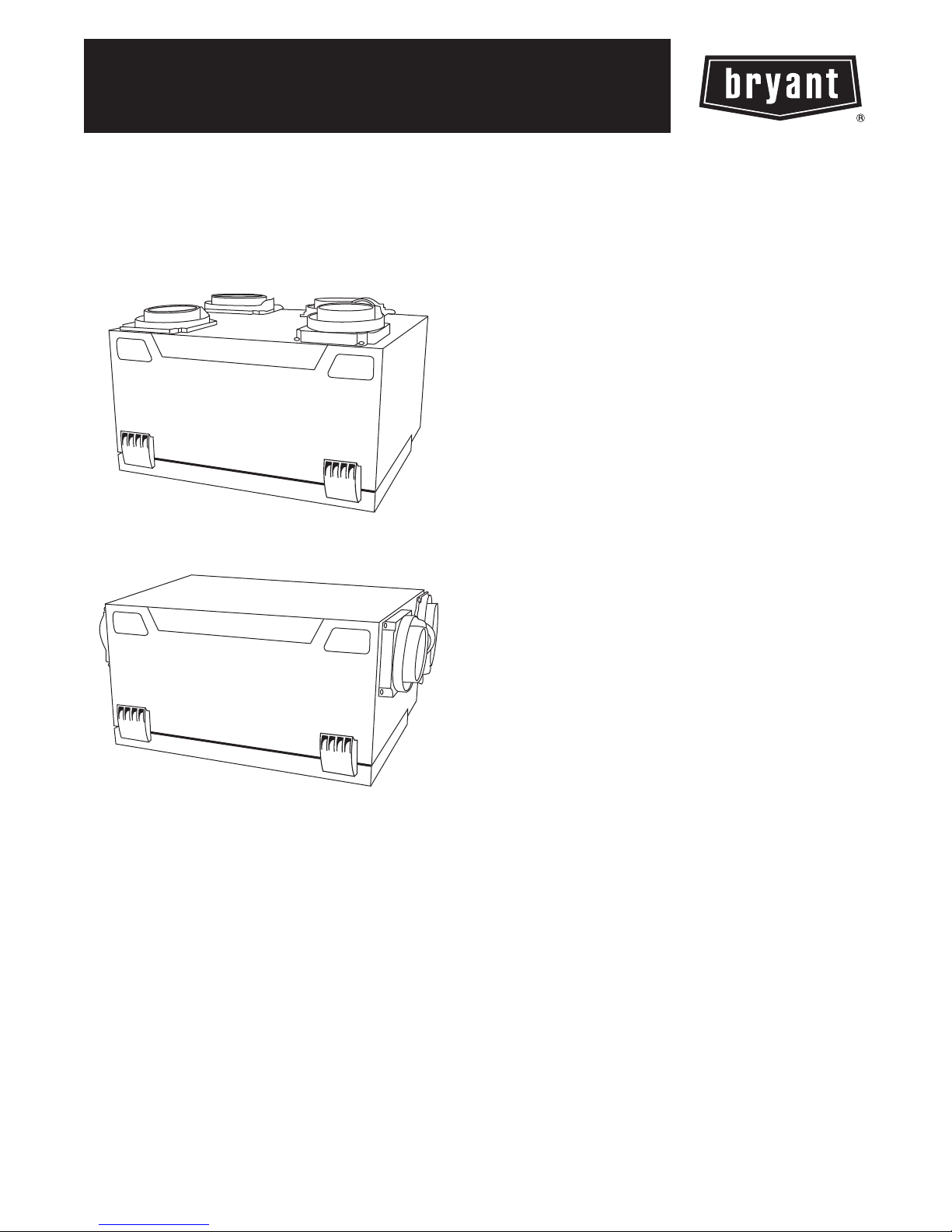
Fig. 1 -- ERVBBSVB / HRVBBSVB
Fig. 2 -- ERVBBSHB / HRVBBSHB
A05229
A05330
Energy Recovery Ventilation (ERV) and Heat Recovery Ventilation
(HRV) systems offered by Bryant are the finest on the market
today. These units provide efficient and cost effective heat and
energy recovery during the heating and cooling season when
needed most.
As temperatures drop below 23_F(--5_C), indoor air is recirculated
periodically through the heat exchanger core to prevent frost from
forming. Competitors’ methods of supplementary electric defrost
waste energy. Unlike rotary wheel heat exchangers which mix air
streams, these cross--flow or counterflow heat exchangers ensure
that there is no mixing of the stale air stream with the fresh outdoor
air stream.
A filter installed on the incoming outdoor air stream removes large
airborne particles from the intake air stream before they enter the
heat exchanger and reduces the maintenance required. The units’
acoustically engineered design makes the Bryant ERVs and HRVs
are the quietest on the market and ensures that comfort is felt, not
heard.
Unlatching two (2) suitcase style latches allows easy removal of the
filters and core for cleaning.
NOTE: The HRV should not be installed in an attic or
unconditioned space unless provisions are made for drain--line
freezing and condensation.
STANDARD FEATURES
S Drainless design -- ERVs / Drains provided -- HRVs
S Integrated airflow balancing points
S High pressure blowers
S Onboard control for continuous high/low ventilator operation
S Energy saving defrost cycle
S Cross--flow, counterflow heat exchangers
S One filter on incoming air; one filter on outgoing air to protect
core
S No--tools maintenance
S Enthalpic heat exchanger core -- ERVs
S Polypropylene heat exchanger core -- HRVs
Page 2

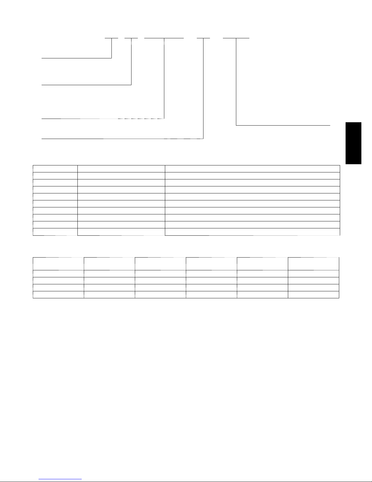
MODEL NUMBER NOMENCLATURE
123456789101112
ERVBBSHB1100
Product Type Maximum Capacity
ERV -- Energy Recovery Ventilator 100 --- 100 CFM
HRV -- Heat Recovery Ventilator
Electrical Supply
Brand 1 -- 115 Volts
BB -- Bryant
Style
SHB -- Small Horizontal
SVB -- Small Vertical
ERV / HRV
Climate Map for Energy and Heat Recovery Ventilators
Edmonton
Vancouver
Salem
Sacramento
Honolulu
HRV Recommended
Boise
Helena
Salt Lake
City
Calgary
Regina
Denver
Winnipeg
Bismark
Austin
Minneapolis
Des Moines
Topeka
Oklahoma City
Green Bay
Madison
Springfield
Baton Rouge
Timmins
Milwaukee
Chicago
Indianapolis
Nashville
Detroit
Atlanta
Ottawa
Harrisburg
Washington D.C.
Columbia
Orlando
Montreal
Syracuse
Hartford
Raleigh
Boston
ERV Recommended w/HRV or ERV Wall Control
ERV Recommended
2
Page 3
VENTILATOR ACCESSORY NUMBER NOMENCLATURE
123456789101112
KVBCN0101BBS
Product Control Description
KV -- Ventilator Accessory Kit BBS -- Bryant Basic Control
BLC -- Bryant Latent Control
Series BLT -- Bryant OneTouch Control
A -- Original Series BST -- Bryant Standard Control
B -- Second Series Accessory Description
HCO -- Concentric Intake/Exhaust Hood
Type HOD -- Intake Hood
AC01 -- Accessory KIT -- Airflow Measuring Kit
CN01 -- Control Timer Description
TM01 -- Timer 20C -- 20 Minute Timer Kit
60M -- 60 Minute Timer Kit
Package Quantity
01 -- Single Pack
KIT NUMBER DESCRIPTION WHERE USED
KVAAC0101HOD Exterior Intake and Exhaust Hood 2Required
KVAAC0101HCO Concentric Intake and Exhaust Hood Used as a single intake/exhaust for SVB1100, SHB1100 models only
KVBCN0101CBS Basic HRV Control Used with all HRVs
KVBCN0101CLC Latent Control Used with ERVs only
KVBCN0101CLT Bryant OneTouch Control Used with all ERVs and HRVs as a main wall control
KVBCN0101CST Standard HRV Control Used with all HRVs
KVATM010120C 20 Minute Push Button Timer Used with all HRVs when 20 minute manual operation is required
KVATM010160M 60 Minute Timer Used with all HRVs, time is adju stable between 10 and 60 minutes
KVBAC0101KIT Airflow Measuring Kit Used with all ERVs and HRVs to balance intake/exhaust airflow
ERV / HRV
CONTROL
DESCRIPTION
Latent Yes Yes No Ye s Ye s
OneTouch Yes No No Ye s Ye s
Basic Yes No No Yes No
Standard Yes Yes Yes Yes Yes
FAN SPEED
CONTROL
HUMIDISTAT
CONTROL
DEHUMIDISTAT
CONTROL
CONTINUOUS
MODE
Control features
Basic Control:
Allows the user to manually set fan speed to low or high as
required to maximize comfort.
Standard Control:
Offers automatic dehumidistat control and the option to select
continuous or intermittent fan operation. Setting the wall control to
low will activate the continuous mode.
OneTouch Control:
Allows control of ventilator with the touch of a button. This
control will operate as a main wall control. The OneTouch will
operate the unit in Intermittent Mode (20 minutes per hour),
continuous low speed, continuous high speed, and off.
Latent Control (ERVsonly):
Low Exchange Mode—If the relative humidity inside the building
is lower than selected, air exchange would occur with the outside at
high speed. If the relative humidity inside the building is higher
than selected, air exchange would occur with the outside at low
speed. This ensures continuous air exchange for constant air
quality.
Intermittent Mode—If the relative humidity inside the building is
higher than selected, no air exchange would occur and the system
would turn off. If the relative humidity inside the building is lower
than selected, air exchange would occur with the outside at high
speed. This mode is ideal for maintaining the proper humidity level
when the continuous mode cannot.
Automatic Defrost Cycle Features
All models offer a non--electric defrost cycle feature which
prevents frost and ice buildup within the heat recovery core. When
the outside air temperature falls below 23_F(--5_C) it is
electronically sensed and the dampers close the outside air ports.
This allows warm indoor air to recirculate within the heat recovery
core. The frequency of this cycle increases as the outside air
temperature decreases.
INTERMITTENT
MODE
3
Page 4

23_F T O --- 1 7 _F
MODEL
DEFROST* EXCHANGE{ DEFROST* EXCHANGE{
ERVBBSHB
HRVBBSHB
ERVBBSVB
HRVBBSVB
* All defrost times are in the standard mode (as shipped)
{ Time between defrost when within specified temperature range
8 Minutes 25 Minutes 10 Minutes 22 Minutes
8 Minutes 25 Minutes 10 Minutes 22 Minutes
1
( --- 5 _C T O --- 2 7 _C)
2
B E L O W --- 1 7 _F
3
( --- 2 7 _C)
4
Left Side View
ERV / HRV
Fig. 3 -- ERVBBSHB and HRVBBSHB Unit Dimensions
Front View Right Side View
A10126
Key to Unit Port Locations
1
Fresh air to building
Stale air from building
2
3
Fresh air from outside
4
Stale air to outside
1
4
Top View
2 3
Fig. 4 -- ERVBBSVB and HRVBBSVB Unit Dimensions
Side View
A10099
4
Page 5

PHYSICAL DATA
MODEL ERVBBSVB1100 ERVBBSHB1100 HRVBBSVB1100 HRVBBSHB1100
Port Locations Top Side Top Side
Core Type
Core Exchange Area 56 sq. ft. (5.2m
Weight
lb (kg)
Shipping Weight
lb (kg)
Shipping Dimensions
in. (mm)
Height
Width
Depth
Voltage 120 120 120 120
Max Power (Watts) 104 104 100 100
Max Amps 0.87 0.87 0.85 0.85
NOTE: Drain Connector Kits are supplied with HRVs only. They are not necessary with ERVs.
Enthalpic transfer media
with plastic stack
42 (19) 42 (19) 42 (19) 42 (19)
48 (22) 48 (22) 48 (22) 48 (22)
25.5 (648)
17.5 (445)
23.0 (584)
2)
Ventilator Sizing
Tables 1 and 2 should be used to determine the required airflow for a home. These guidelines are taken from ASHRAE 62.2--2007.
Enthalpic transfer media
with plastic stack
56 sq. ft. (5.2m
30.0 (762)
15.0 (381)
23.0 (584)
2)
Polypropylene Cross
Flow
55 sq. ft. (5.1m
25.5 (648)
17.5 (445)
23.0 (584)
2)
Polypropylene Cross
Flow
55 sq. ft. (5.1m
30.0 (762)
15.0 (381)
23.0 (584)
2)
ERV / HRV
Table 1 – Ventilation Air Requirements, cfm
FLOOR
AREA (ft
1501---3000 45 60 75 90 105
3001---4500 60 75 90 105 120
4501---6000 75 90 105 120 135
6001---7500 90 105 120 135 150
2
)
0 --- 1 2 --- 3 4 --- 5 6 --- 7 >7
<1500 30 45 60 75 90
>7500 105 120 135 150 165
BEDROOMS
Table 2 – Ventilation Air Requirements, L/s
FLOOR
AREA (m
139.1---279 21 28 35 42 50
279.1---418 28 35 42 50 57
418.1---557 35 42 50 57 64
557.1---697 42 50 57 64 71
2
)
0 --- 1 2 --- 3 4 --- 5 6 --- 7 >7
<139 14 21 28 35 42
>697 50 57 64 71 78
BEDROOMS
5
Page 6

HVI Rated Energy Performance
PERFORMANCE DATA
SUPPLY TEMP NET AIR FLOW
_C _F L/S CFM
0 32 21 45 42 68 79 0.63
0 32 27 58 46 68 76 0.58
0 32 41 87 70 63 71 0.48
--- 25 --- 1 3 22 47 58 55 78 0.60
0 32 21 45 42 68 79 0.63
0 32 27 58 46 68 76 0.58
0 32 41 87 70 63 71 0.48
--- 25 --- 1 3 22 47 58 55 78 0.60
0 32 18 39 37 66 78 0.03
0 32 24 50 44 65 74 0.01
0 32 40 85 68 59 68 0.01
--- 25 --- 1 3 23 48 56 57 84 0.03
0 32 18 39 37 66 78 0.03
0 32 24 50 44 65 74 0.01
0 32 40 85 68 59 68 0.01
--- 25 --- 1 3 23 48 56 57 84 0.03
ERV / HRV
MODEL MODE
ERVBBSHB1100
ERVBBSVB1100
HRVBBSHB1100
HRVBBSVB1100
Heating
Cooling 35 95 21 44 42 52
Heating
Cooling 35 95 21 44 42 52
Heating
Cooling 35 95
Heating
Cooling 35 95
Ventilation Performance
EXT. STATIC
MODEL
ERVBBSHB1100
ERVBBSVB1100
HRVBBSHB1100
HRVBBSVB1100
NOTE: For additional data points, refer to HVI Directory at www.hvi.org
PRESSURE
PA IN WC L/S CFM L/ S CFM L/S CFM
25 0.1 55 116 56 119 55 116
50 0.2 53 113 54 115 53 112
100 0.4 50 105 51 108 50 105
200 0.8 42 89 43 92 41 87
250 1.0 38 80 39 83 37 78
25 0.1 55 116 56 119 55 116
50 0.2 53 113 54 115 53 112
100 0.4 50 105 51 108 50 105
200 0.8 42 89 43 92 41 87
250 1.0 38 80 39 83 37 78
25 0.1 52 110 53 112 57 121
50 0.2 50 106 51 108 54 115
100 0.4 46 97 47 100 50 106
200 0.8 37 79 38 81 42 90
250 1.0 33 70 34 72 37 79
25 0.1 52 110 53 112 57 121
50 0.2 50 106 51 108 54 115
100 0.4 46 97 47 100 50 106
200 0.8 37 79 38 81 42 90
250 1.0 33 70 34 72 37 79
POWER
CONSUMED
(WATTS)
NET SUPPLY AIR FLOW
SENSIBLE
RECOVERY
EFFICIENCY
SUPPLY EXHAUST
APPARENT
SENSIBLE
EFFECTIVENESS
GROSS AIR FLOW
LATENT
RECOVERY
MOISTURE
TRANSFER
TOTAL
RECOVERY
EFFICIENCY
6
Page 7

VENTILATOR INSTALLED WITH FORCED AIR SYSTEM
ERV / HRV
VENTILATOR INSTALLED WITH INDEPENDENT AIR DISTRIBUTION
A10105
A10106
7
Page 8

ERV / HRV
E2010 Bryant Heating & Cooling Systems D 7310 W. Morris St. D Indianapolis, IN 46231 Printed in U.S.A. Edition Date: 05/10
Manufacturer reserves the right to discontinue, or change at any time, specifications or designs without notice and without incurri ng obligations.
8
Catalog No. PDSERVHRV--- 0 1
Replaces: NEW
 Loading...