

Bryant ERVBBLHU1150, ERVBBLHU1200 Installation, Start-up, And Operating Instructions Manual
Page 1
Installation, Start-Up, and
Operating Instructions
ERVBBLHU
ENERGY RECOVERY VENTILATOR
NOTE: Read the entire instruction manual before starting the
installation.
This symbol → indicates a change since the last issue.
TABLE OF CONTENTS
SAFETY CONSIDERATIONS .....................................................1
INTRODUCTION ..........................................................................1
INSTALLATION CONSIDERATIONS .......................................1
Inspect Equipment ....................................................................1
Select Location..........................................................................2
COMPONENT DESCRIPTION ....................................................2
INSTALLATION ...........................................................................3
Mount Unit................................................................................3
Independent System Application..............................................3
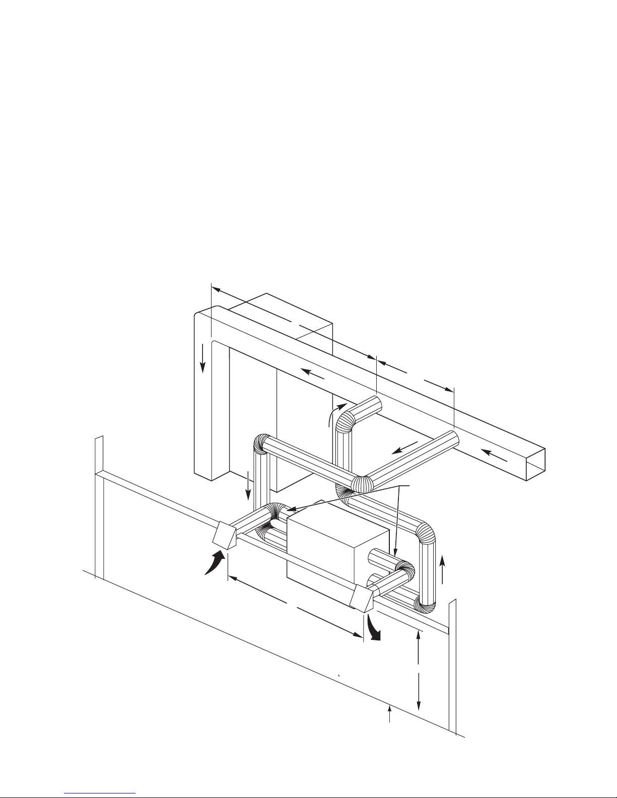
Forced-Air Application.............................................................3
Connect Ducts to ERV .............................................................3
Locate and Install Exterior Hoods ...........................................3
Condensate Drain......................................................................4
Wall Control..............................................................................4
ELECTRICAL CONNECTIONS ..................................................4
115–vac Wiring.........................................................................4
12–vdc Wiring ..........................................................................4
ACCESSORIES..............................................................................4
Interlock Relay..........................................................................4
20 Minute Timer.......................................................................5
60 Minute Adjustable Timer ....................................................5
BALANCING ERV .......................................................................5
Balancing Dampers...................................................................6
Flow Collar ...............................................................................6
CONTROL BOARD OPERATION ..............................................8
Board Function..........................................................................8
Defrost.......................................................................................8
OFF and INTERMITTENT/OFF Mode...................................8
High-Speed Air Exchange ........................................................8
Low-Speed Air Exchange.........................................................9
CARE AND MAINTENANCE.....................................................9
Door.........................................................................................10
Filter ........................................................................................10
Blower Motor and Wheel.......................................................10
Cleaning Core .........................................................................10
TROUBLESHOOTING ...............................................................10
Wall Control............................................................................10
Control Board..........................................................................10
Blower Motor..........................................................................10
Blower Speed Selection..........................................................11
SAFETY CONSIDERATIONS
Installation and servicing of this heating equipment can be
hazardous due to mechanical and electrical components. Only
trained and qualified personnel should install, repair, or service
heating equipment.
Untrained personnel can perform basic maintenance functions
such as cleaning and replacing air filters. All other operations must
be performed by trained service personnel. When working on this
equipment, observe precautions in the literature, on tags, and on
labels attached to or shipped with the unit and other safety
precautions that may apply.
Cancels: II ERV-64–2 II ERV-64–3
4–05
A00092
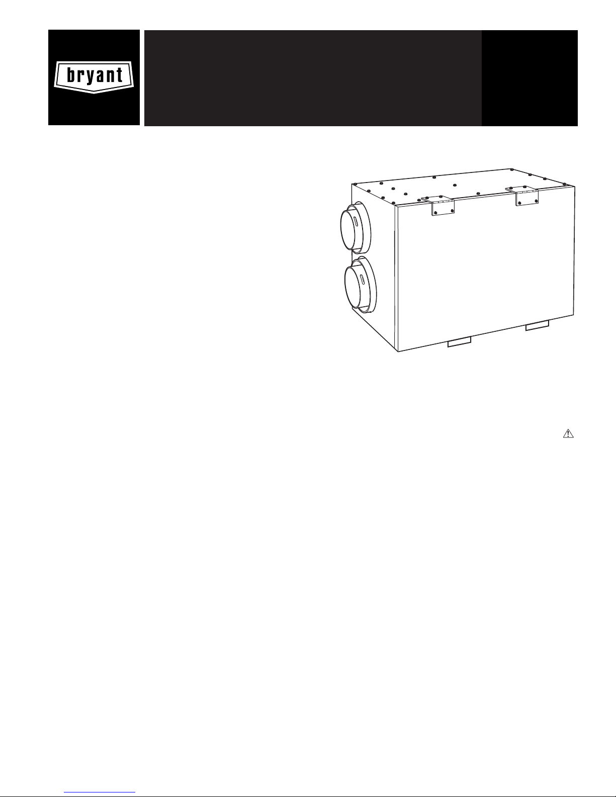
Fig. 1–ERVBBLHU Energy Recovery Ventilator
Follow all safety codes. Installation must be in compliance with
local and national building codes. Wear safety glasses and work
gloves. Have a fire extinguisher available during start-up and
adjustment procedures and service calls.
Recognize safety information. This is the safety-alert symbol
When you see this symbol on the furnace and in instructions or
manuals, be alert to the potential for personal injury.
Understand the signal words DANGER, WARNING, or CAUTION. These words are used with the safety-alert symbol. DANGER identifies the most serious hazards which will result in severe
personal injury or death. WARNING signifies a hazard that could
result in personal injury or death. CAUTION is used to identify
unsafe practices which would result in personal injury or product
or property damage. NOTE is used to highlight suggestions which
will result in enhanced installation, reliability or operation.
INTRODUCTION
The ERVBBLHU Energy Recovery Ventilator (ERV) is used to
exchange indoor stale air with outside fresh air. The ERV unit is
equipped with a special energy recovery core which transfers both
sensible and latent heat with the fresh incoming air. The cross-flow
design core allows entering and leaving air streams to transfer heat
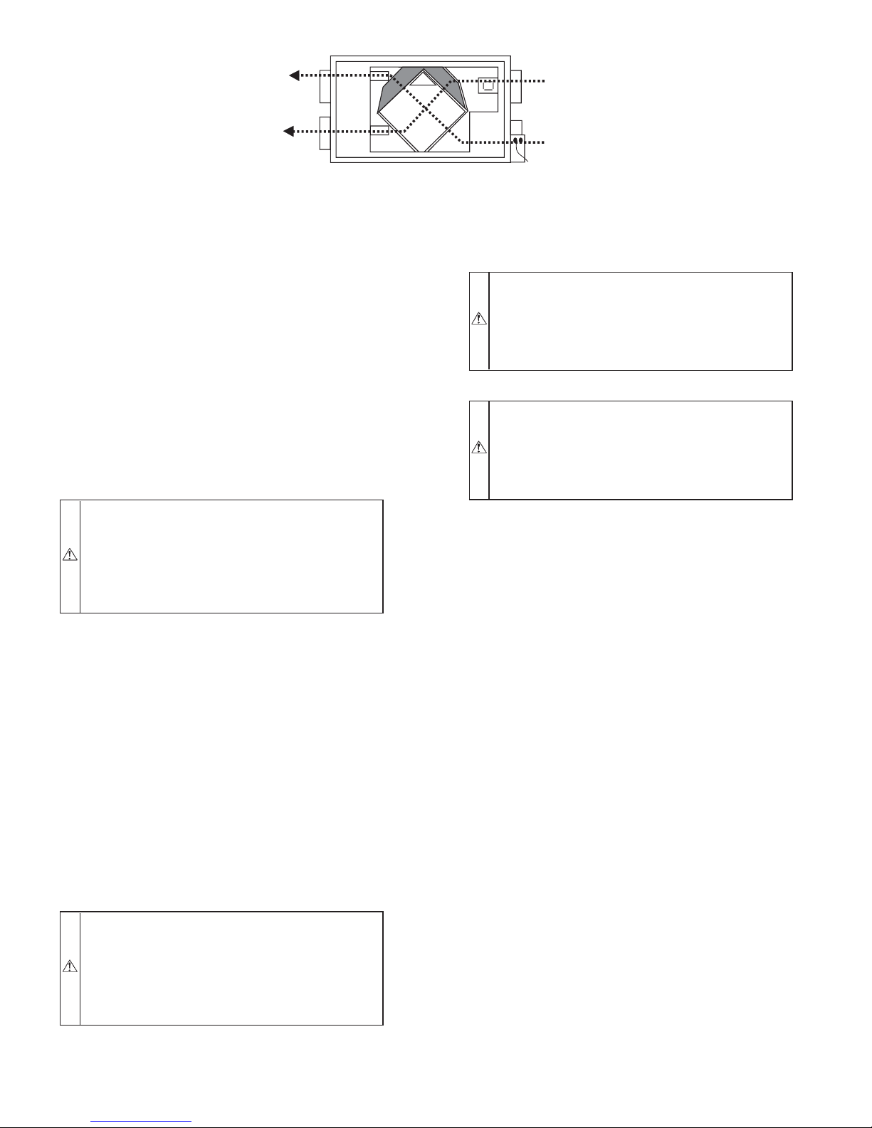
energy without mixing (See Fig. 14).
The model ERVBBLHU is available in 2 sizes with airflow ranges
of 64–152 CFM, and 117–214 CFM. The design of this unit is
horizontal. Special attention should be given to duct application,
balancing the ERV, and locating unit for easy access and routine
maintenance.
INSTALLATION CONSIDERATIONS
I. INSPECT EQUIPMENT
Move carton to final installation location. Remove ERVBBLHU
from carton taking care not to damage unit. Remove all packaging
and inspect unit for damage. Remove parts bag from inside unit.
File claim with shipping company if shipment is damaged or
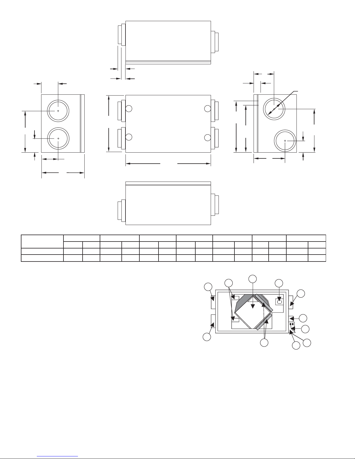
incomplete. Check to make sure ERV unit matches Fig. 2.
.
—1—
Page 2
3
2
⁄16"
(56.2)
3
4
⁄4"
(120.6)
4 PLCS
20"
(508.0)
4
1"
(25.4)
2 PLCS
1
D
2
3
5
2
⁄16"
(58.7)
1
18
⁄8"
(460.4)
16
(428.6)
C
G
7
5
⁄8" DIA
(149.2)
4 PLCS
7
⁄8"
15"
(381.0)
F
B
1
30
⁄4"
(768.3)
E
A
NOTES:
1. FRESH AIR FROM OUTSIDE TO ERV
2. FRESH AIR FROM ERV TO HOUSE
3. STALE AIR FROM HOUSE TO ERV
4. STALE AIR FROM ERV TO OUTSIDE
MODEL NO. A B C D E F G
in. mm. in. mm. in. mm. in. mm. in. mm. in. mm. in. mm.
ERVBBLHU1150 15-1/8 384.2 4-1/16 104 5-5/8 143.3 14-1/2 368.9 10-3/8 288.9 4-3/8 111.3 7-3/4 196.9
ERVBBLHU1200 19 483 5-13/16 147.7 5-1/16 128.6 14-1/2 368.9 11-3/16 283.9 4-3/8 111.3 10-1/16 255.6
Fig. 2–Dimensional Drawing ERVBBLHU
II. SELECT LOCATION
The ERV should be located in a conditioned space and in close
proximity to a fused power source. It should be easily accessible
for routine maintenance.
3
6
5
11
2
If ERV is installed independent of a forced-air system, unit should
be located near the center of the air distribution system. If ERV is
installed in conjunction with a forced-air system, unit should be
located next (or close to) the indoor equipment.
1
10
COMPONENT DESCRIPTION
The following lists components of the ERVBBLHU (See Fig. 3).
8
4
7
9
1. Stale air return from building connected to return-air duct
system.
2. Fresh-air intake connected to outdoor-air inlet hood.
Fig. 3–ERVBBLHU Cross-Flow
3. Exhaust-air connected to outdoor-air exhaust hood.
4. Mechanical filters trap dust contained in the air.
5. Energy recovery core is a cross-flow type. It transfers
sensible and latent energy between the 2 airstreams.
6. Blowers bring in fresh-air from outside and exhaust stale-air
to outside.
9. Terminal connector block for wiring wall and timer controls.
10. Electrical cord connects to standard 115–v outlet.
11. Damper motor.
7. Electronic control circuit board ensures proper operation of
unit.
8. Fresh-air supply connected to return-air duct system.
A00093
A00113
—2—
Page 3
Maximum length of duct for the system should be designed
according to the highest speed of the unit. Refer to specifications
listed in unit Product Data Sheet for ventilation capacities.
III. FORCED-AIR APPLICATION
Most ERV applications will be installed in conjunction with new
or existing forced-air systems. To operate properly, the fresh-air
supply and stale-air return from ERV connect directly to return-air
duct system. This is how the ERV distributes fresh air and removes
stale air from inside of the building (See Fig. 7). For these
installations, furnace or fan coil blower must be interlocked and
operate continuously whenever ERV is energized.
→
Interlock relay kit Part No. KVAAC0101VIR is available and
designed to interlock ERV with indoor equipment blower. When
ERV is energized, R and G circuit inside of furnace or fan coil will
energize. See Fig. 10 and interlock relay kit for additional
information and Installation Instructions.
NOTE: The fresh air from ERV is introduced into return-air duct
at a point no less than 6 ft upstream of furnace or fan coil. This
connection should be direct (See Fig. 7). This is to allow incoming
fresh-air to mix before entering indoor equipment.
IV. CONNECT DUCTS TO ERV
A92269
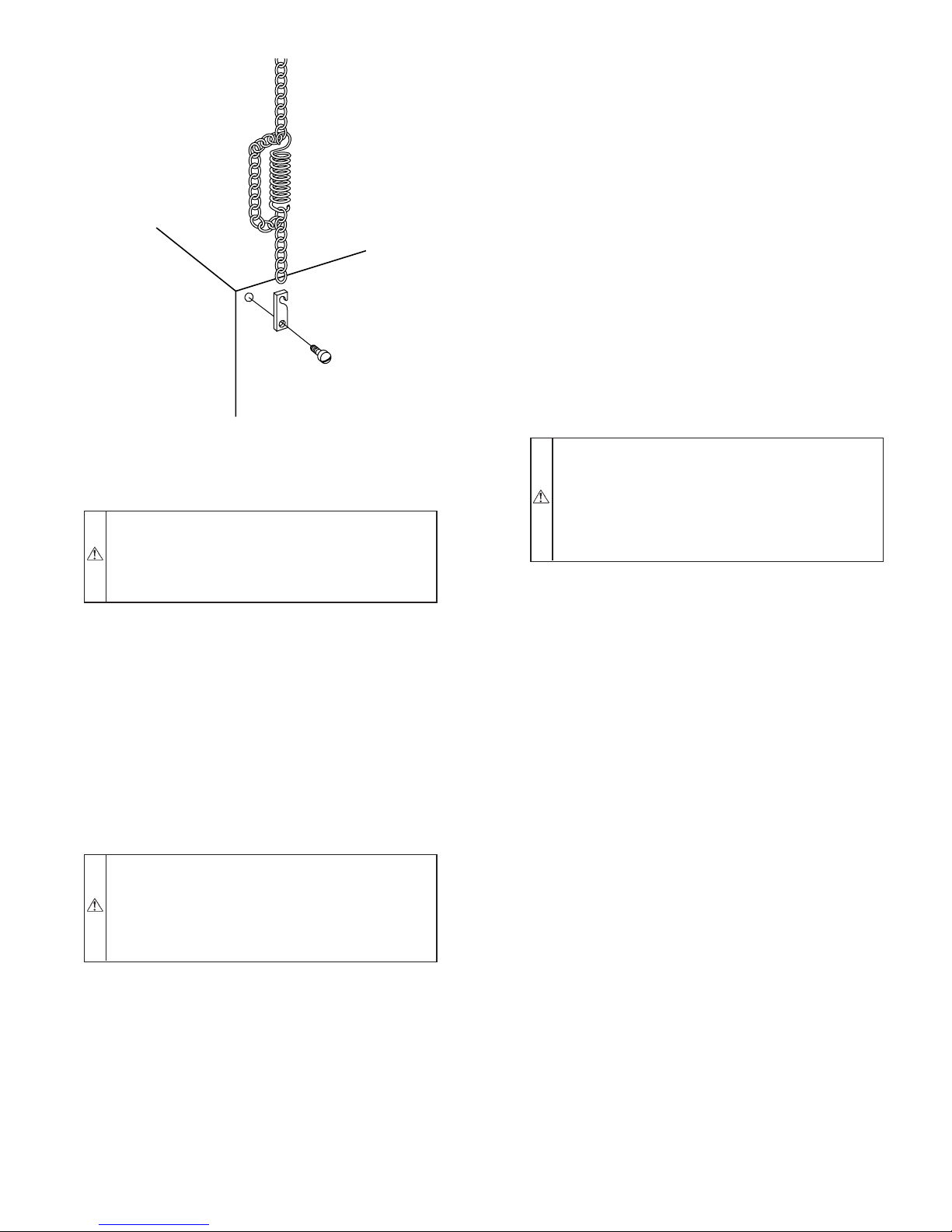
Fig. 4–Chain Spring Installation
INSTALLATION
CAUTION: UNIT DAMAGE HAZARD
Failure to follow this caution may result in reduced life of
this unit.
Do not install ERV in a corrosive or contaminated
atmosphere.
I. MOUNT UNIT
The ERV can be suspended from floor joists or rafters using chains
and 4 springs. Attach a metal hanging bracket to all 4 sides of the
cabinet (See Fig. 4). The unit may be installed on a shelf, if an
isolation pad is provided to dampen vibration. Unit should always
be installed as level as possible.
II. INDEPENDENT SYSTEM APPLICATION
In the absence of a forced-air system and a typical duct system
layout, the ERV can be applied as an independent stand alone unit.
To ensure comfort, this type of application involves running both
fresh-air, and return-air registers (or stale-air pick-up registers)
throughout the home.
CAUTION: CARBON MONOXIDE POISONING
HAZARD
Failure to follow this warning could result in personal
injury or death.
Do not install return-air registers (or stale-air pickup
registers) in same room as gas furnace or water heater
Fresh-air registers are normally located in bedrooms, dining
rooms, living rooms, and basements. It is recommended that
registers be placed 6 to 12 in. from the ceiling on an interior wall
and airflow directed towards ceiling. If registers are floor installed,
airflow should be directed toward the wall.
Return air (or stale-air pickup registers) are normally located to
draw from kitchen, bathroom, basement, or other rooms where
stale-air can exist.
Proper size and type of registers must be used to minimize pressure
drop. The velocity of airflow through register should not be above
400 feet per minute.
CAUTION: PROPERTY DAMAGE HAZARD
Failure to follow this caution may result in minor
property damage from sweating duct or loss of unit
efficiency and capacity.
ERV should be installed in a conditioned space with
insulated flex duct for supply and exhaust air to the
outdoor ambient.
Insulated flexible duct is required on both fresh-air inlet and
exhaust-air outlet ducts connecting to exterior wall. When using
insulated flexible duct, the vapor barrier of the flexible ducts must
be taped very tight to prevent condensation problems. To reduce
pressure drop, stretch the flex duct and support it in a proper
manner to avoid reduced airflow.
When connecting the ERV to a return-air duct system, insulated
flexible duct can be used. However, when metal or rigid ducts are
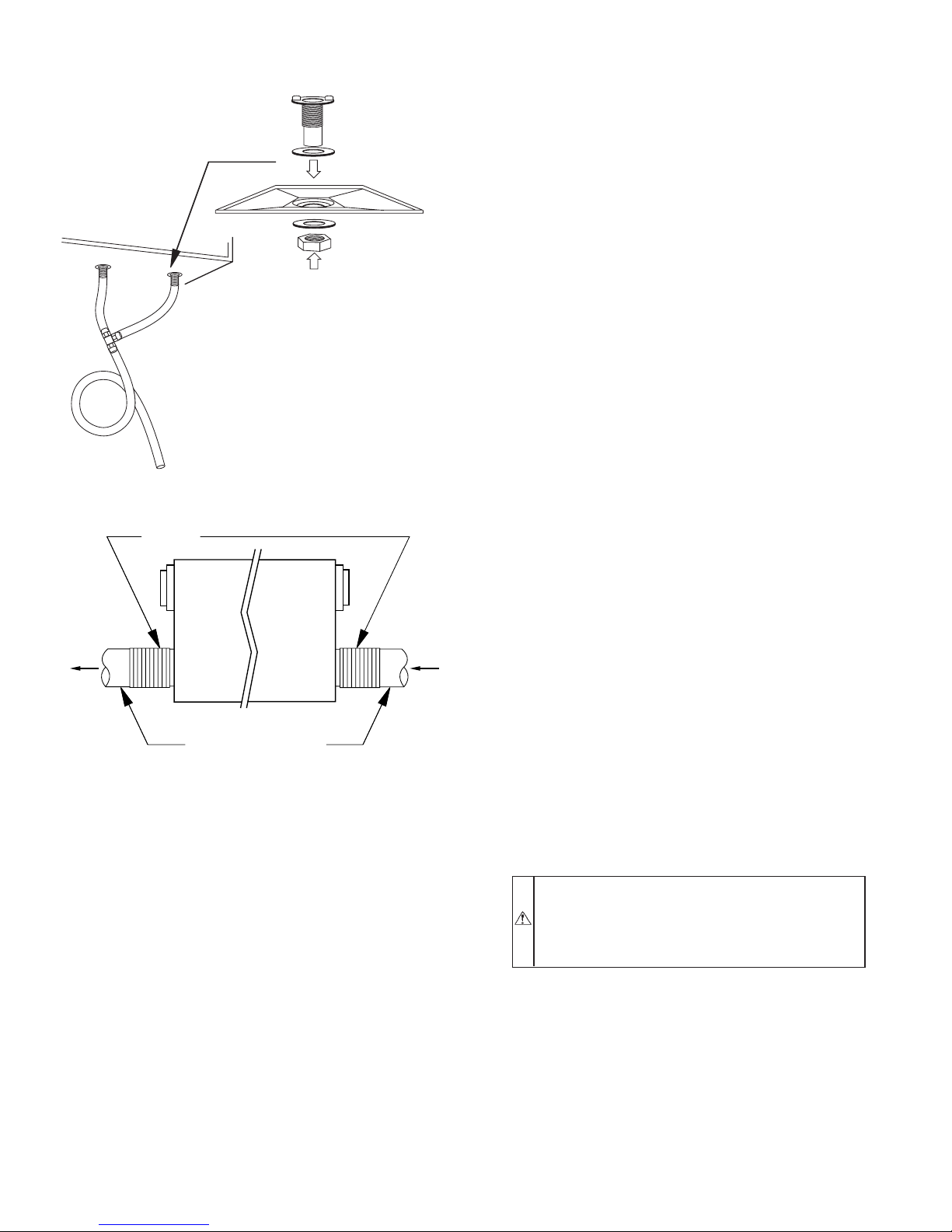
applied use approximately 18–in. of flexible duct at ERV ports for
fresh-air supply, and stale-air return (See Fig. 6). This can act as a
silencer when connecting ducts to return-air duct system. This
should eliminate transmission of noise or vibration from unit to
main duct system. In addition, there are four 30–in. duct ties
provided to help fasten flexible duct to port on ERV.
V. LOCATE AND INSTALL EXTERIOR HOODS
IMPORTANT: To prevent condensation problems, insulated
flexible ducts are required on both fresh-air inlet and exhaust-air
outlet ducts connecting between ERV and exterior wall.
Fresh-air intake and stale-air exhaust must be separated by at least
6 ft. Fresh-air intake must be positioned at least 10ft. from nearest
dryer vent, furnace exhaust, driveway, gas meter, or oil fill pipe.
Fresh-air intake must be positioned as far as possible from garbage
containers and potential chemical fumes. When possible, it is
advised to locate the intake and exhaust hoods on same side of
house or building. The intake and exhaust hoods should never be
located on interior corners or in dead air pockets. (See Fig. 7) Both
intake and exhaust hoods must be 18 in. from ground and at least
12 in. above anticipated snow level.
After selecting proper hood locations, make appropriate size hole
through exterior wall, pass flexible duct through hole and insert
hood tube into duct. Tape duct vapor barrier tightly around hood
tube and insert assembly back into wall and fasten securely.
—3—
Page 4
A99268
Fig. 5–Condensate Drain With Loop Trap
FLEXIBLE
DUCT
FRESH-AIR
SUPPLY
DUCTS CONNECTING TO
RETURN-AIR DUCT SYSTEM
STALE-AIR
RETURN
A98382
Fig. 6–Flexible Duct Fit-Up
VI. CONDENSATE DRAIN
To connect condensate drain, proceed as follows:
1. Insert sleeved grommets into bottom of unit using the
gasket washer and nut (See Fig. 5).
2. Cut two sections of plastic tubing, about 12” long and attach
them to each drain.
3. Join the two short sections of tubing to the “T” connector
and the main tube as shown.
4. Make a loop in the tubing below the “T” connector to create
a trap to prevent sewer gases from entering the ventilation
system (See Fig. 5).
5. Connect unit drain to building’s main drain. Provide slight
slope from unit for run-off.
VII. WALL CONTROL
1. Location
The ERV wall control is unique to this unit. The ERV will not
operate without it. This control senses humidity not temperature. It
must be located in an area where it will continually monitor fresh
air circulating within the home. Install ERV wall control as close
as possible to main system thermostat and follow same guidelines
as installing a thermostat (locate approximately 5 ft. above floor,
mount on an inside partitioning wall, etc.).
2. Wiring
Remove top cover assembly from wall control and pass thermostat
wire through hole located on back of control before attaching to
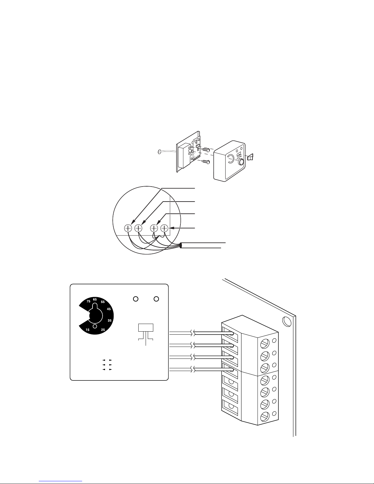
wall. Connect Y, R, G, and B (yellow, red, green, and black)
between wall control and ERV circuit board following color code
(See Fig. 8 and 9). Replace top cover assembly.
NOTE: ERV wall control and circuit board operate on 12vdc.
3. Operation
The ERV wall control has 3 basic modes of operation, OFF, LOW,
and INTERMITTENT. Be sure that all modes of operation are
fully functional. See Table 1 indicating standard control operation.
OFF — When wall control is OFF, ERV is de-energized and both
LED’s are off.
LOW — This mode ensures continuous air exchange with outside
at all times. If relative humidity level inside of building is higher
than setpoint, then air exchange will occur at low speed. If relative
humidity level inside of building is lower than setpoint, then air
exchange occurs at high speed.
INTERMITTENT — If relative humidity level inside of building
is higher than setpoint, then no air exchange will occur and ERV
shuts off. If relative humidity level inside building is lower than
setpoint, then air exchange occurs at high speed, and shuts down
ERV when humidity level reaches set point. This mode is ideal for
maintaining proper humidity level when continuous mode cannot.
To ensure highest degree of humidity control in cooling season,
intermittent mode should not be used.
4. Humidity Selection
The humidity selector is a built-in humidity controller designed to
properly control humidity level in a house during summer months.
This acts like a limit switch. See Table 2 to select maximum
humidity level. If the house becomes too dry in winter months, put
wall control in INTERMITTENT mode and turn down humidity
selector to provide ventilation less frequently.
5. Latent Control
NOTE: To ensure highest degree of humidity control in cooling
season, the INTERMITTENT mode should be used. See Table 1
and reference LOW and INTERMITTENT control operation listed
above.
ELECTRICAL CONNECTIONS
I. 115–VAC WIRING
The ERV operates on 115vac. It comes with a power cord attached
to unit and ready to plug into a fused outlet. Unit must be grounded
for proper operation.
All electrical connections must comply with National and Local
Electrical Codes, or other ordinances that might apply.
CAUTION: ELECTRICAL / FIRE HAZARD
Failure to follow this warning could result in property or
unit damage.
Do not use an extension cord as a power source for
operating the ERV.
II. 12–VDC WIRING
The ERV circuit board, wall control, and accessories operate on
12vdc. See section, Wall Control, item Wiring, and Fig. 8 and 9 for
more information.
ACCESSORIES
I. INTERLOCK RELAY
→
The interlock relay kit, Part No. KVAAC0101VIR is required
when installing ERV into a forced-air heating and cooling system
(See Fig. 10). Mount interlock relay inside of unit below control
box assembly. For additional information, refer to Installation
Instructions supplied with the interlock relay kit.
—4—
Page 5
The purpose of the interlock relay kit is to energize indoor system
equipment (furnace or fan coil) blower whenever ERV is calling.
If ERV is energized, and indoor system equipment is not, interlock
relay will energize and make R and G at indoor equipment. This
will insure fresh air distribution throughout the building via the
central duct system.
II. 20 MINUTE TIMER
A push button timer can be used to override the wall control and
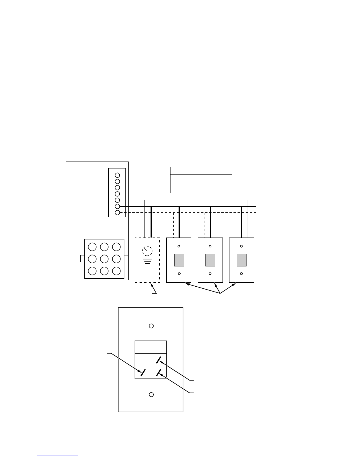
put ERV into high speed for 20 minutes. Connect switches in
parallel and connect leads to ERV terminals I, OC, and OL. (See
Fig. 10) Push button locations are ideal in special activity areas,
such as bathrooms, or kitchens, where high-speed exhaust operation is needed for a short period of time.
NOTE: The 20 minute timer will not function properly unless
ERV wall control is applied and working correctly. Timing
function is internal to electronic circuit board. It is activated by a
momentary contact between OC and OL. The I connection is to
illuminate the push button. The maximum number of push button
timers that can be applied is 5.
III. 60 MINUTE ADJUSTABLE TIMER
A 60 minute adjustable timer can also be used to override wall
control and put ERV into high-speed operation for a select amount
of time. Connect timer in parallel with push button timers, or to
ERV terminals OC and OL (See Fig. 11).
The 60 minute timer will provide a minimum of 10 minutes, and
a maximum of 60 minutes of ventilation at high speed.
BALANCING ERV
Balancing intake and exhaust airflow is very important for proper
system operation and optimum performance when applying an
ERV. Unit balancing prevents a positive and/or negative pressure
within a home. Balancing the ERV is done by applying temporary
flow collars and adjusting the balancing dampers to the fresh air
intake and stale air exhaust ducts (See Fig. 12). Airflow is
temporarily determined by connecting a magnehelic gage to the
temporary flow collar (See Fig. 13). Both flow collars and
magnehelic gage are included in the accessory start-up balancing
kit.
6′
FURNACE
INLET HOOD
REAR
18″MIN
INSULATED DUCT CONNECTING
ERV
6′
EXHAUST HOOD
FRESH AIR & EXHAUST TO
OUTSIDE
NOTE: Supply & exhaust ducts have
internal balancing dampers
that must be adjusted.
18″
GROUND LEVEL
A00111
Fig. 7–Exhaust Ventilation
—5—
Page 6
If supply-air from outside is greater than exhaust-air from the
house, an imbalance can result over pressurizing the home. If
exhaust-air is greater than supply-air, combustion appliances may
backdraft, bringing exhaust fumes into the house. A balanced
condition will ensure optimum performance, provide satisfied
customers, and avoid expensive callbacks.
Before proceeding with balancing, all windows, doors, and fireplace flues should be tightly closed. No exhaust system such as
range top exhausts, dryer exhausts, fume hoods, bath or roof fans
should be in operation. The forced-air furnace (if used for
circulation) should be operating in continuous fan mode for normal
operating speed.
I. BALANCING DAMPERS
Balancing dampers (sometimes called butterfly dampers) are
located in the fresh air intake and the stale air exhaust (See Fig. 12)
of the ERV.
II. FLOW COLLAR
Flow Collars are temporary, and should be installed as close to the
ERV as possible and in straightest sections of duct to ensure
accuracy (See Fig. 12). If only one flow collar is available, install
collar in stale-air duct of the ERV, and record airflow. Next, install
collar in the fresh-air duct and record airflow. If two flow collars
are available, it will be much easier to read airflow and properly
adjust dampers to balance unit.
With wall control at maximum speed (high-speed operation) and
furnace or fan coil on continuous fan, connect hoses to flow collar
to a magnehelic gage (See Fig. 13). When balancing the ERV
make sure all doors and windows are closed. All exhaust fans,
cooking ranges, and driers are turned off and the furnace or fan coil
blower is on. The gate must be leveled and zeroed before use to
read accurately. If needle falls below zero, reverse hose connections.
YELLOW
AIR EXCHANGE
% RELATIVE HUM. EXT. TEMP.
60%
55%
45%
21°C+ / 70°F
10°C / 50°F
0°C / 32°F
YR GB
Fig. 8–Typical Wall Control
ON
OFF LOW
INTERMITTENT
+
RED
GREEN
BLACK
A00112
A00112
CONTROL
CONNECTOR
BLACK
GREEN
RED
YELLOW
OLOCIYRGB
A98384
Fig. 9–Control Connector
—6—
Page 7
Measure exhaust air first. It is typically the lowest pressure due to
nature of system and ductwork. Next measure fresh air. If fresh air
reading is higher than exhaust reading, adjust damper until reading
is same. If reading is lower, return to exhaust damper and adjust to
obtain same reading. The label on flow collar can be used to
convert static pressure into airflow.
Once ERV is balanced and dampers are adjusted to equalize
airflow, use tape or drive screw to prevent damper blades from
moving. Remove flow collars and secure ducts. This procedure
should be repeated to ensure unit is balanced properly.
NOTE: The flow collar directional arrow (on flow collar) must be
oriented in the airflow direction of the unit.
NOTE: Some field modification may be required to ensure proper
temporary installation of flow collar during balancing when
insulated flexible duct is used.
NOTE: For airflow pattern, see Fig. 14.
CAUTION: UNIT DAMAGE HAZARD
Failure to follow this caution may result in reduced unit
efficiency, capacity or unit life.
Do NOT use ERV during construction of a house or when
sanding drywall. This type of dust may damage system.
VENTILATION EVALUATION
When ventilation requirement is determined, use Product Data
Digests to reference unit airflow delivery and performance. The
ventilation capacity of an ERV unit while at maximum speed is
defined according to greatest total airflow required. These methods
are derived from the Canadian National Building Code 1990
version and the CSA F326.1 revision.
The following 2 methods can be used to evaluate the approximate
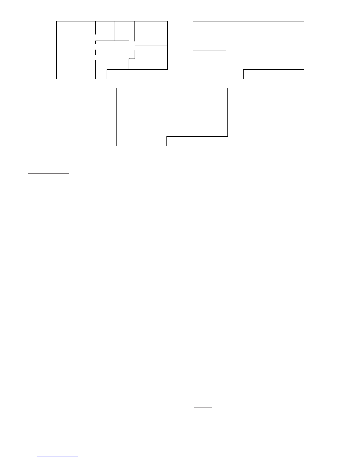
ventilation needs of a house. Accuracy of calculations are dependent upon the information available and knowing critical measurements of the structure (See Fig. 15).
METHOD 1
To calculate approximate ventilation or extend defrost for cold
climate conditions:
The sum of rooms X 10 CFM per room, plus 20 CFM for a master
bedroom or basement are required.
Example: 11 rooms X 10 CFM + 2 X 20 CFM = 150 CFM.
NOTE: The master bedroom and basement are not included in
first part of this equation, but figured in at second part of the
equation.
METHOD 2
To calculate approximate ventilation:
Referencing same example (See Fig. 15).
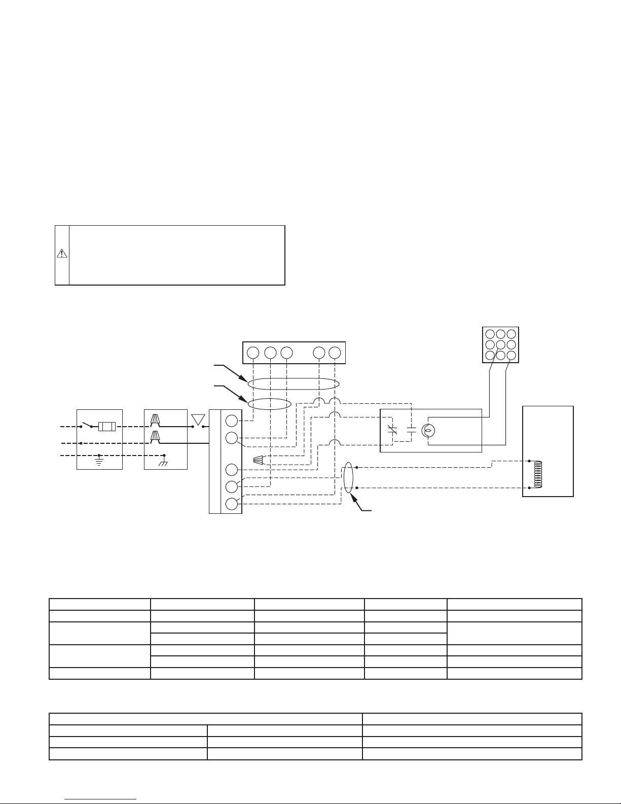
BLK BLK
WHT WHT
GND
115V FIELDSUPPLIED
FUSED
DISCONNECT
NOTE: Connect Y-terminal as
shown for proper operation.
→
MODE HUMIDITY LEVEL BOARD FUNCTION FAN SPEED INDICATOR LED’S
Off Any Off/Intermittent Off OFF
Low Below Setpoint Exchange High High Both ON
Intermittent Below Setpoint Exchange High High Both ON
Below 23°F(-5°C) Any Defrost/Exchange High/Low Both ON
FOUR WIRE
TWO-WIRE
HEATING ONLY
GND
FURNACE
AUXILIARY
J-BOX
Above Setpoint Exchange Low Low
Above Setpoint Off/Intermittent Off ON light on Exchange OFF
THERMOSTAT
TERMINALS
C
W
W
R
G
C
Y
INDOOR UNIT
24V
TERMINAL BLOCK
R
G
Y
Fig. 10–Interlock Relay Wiring Layout
TABLE 1–WALL CONTROL
2
1
TWO
WIRE
9-PIN AMP PLUG
INTERLOCK RELAY
3
120V FROM
VENTILATOR
1
2
3
4
5
6
7
8
9
CONDENSING
UNIT
A05042
OUTSIDE TEMPERATURE PERCENT RELATIVE HUMIDITY
70°F and Above 21°C and above 60 percent
50°F 10°C 55 percent
32°F 0°C 45 percent
TABLE 2–MAXIMUM HUMIDITY LEVELS
—7—
Page 8
Total cu ft. X 0.3 per hr = total. Take total and divide by 60 to get
CFM.
Example:
1320 sq ft. x 8ft in height = 10560 cu ft house
10560 cu ft X 3 floors = 31680 total cu ft in house
31680 cu ft X 0.3 air change per fr = 9500 cu ft
9500 cu ft ÷ 60 minimum per hr = 160 CFM
Conclusion: The total amount of airflow needed is 160 CFM. This
falls within airflow range of a ERVCCLHU1200 size unit.
CONTROL BOARD OPERATION
I. BOARD FUNCTION
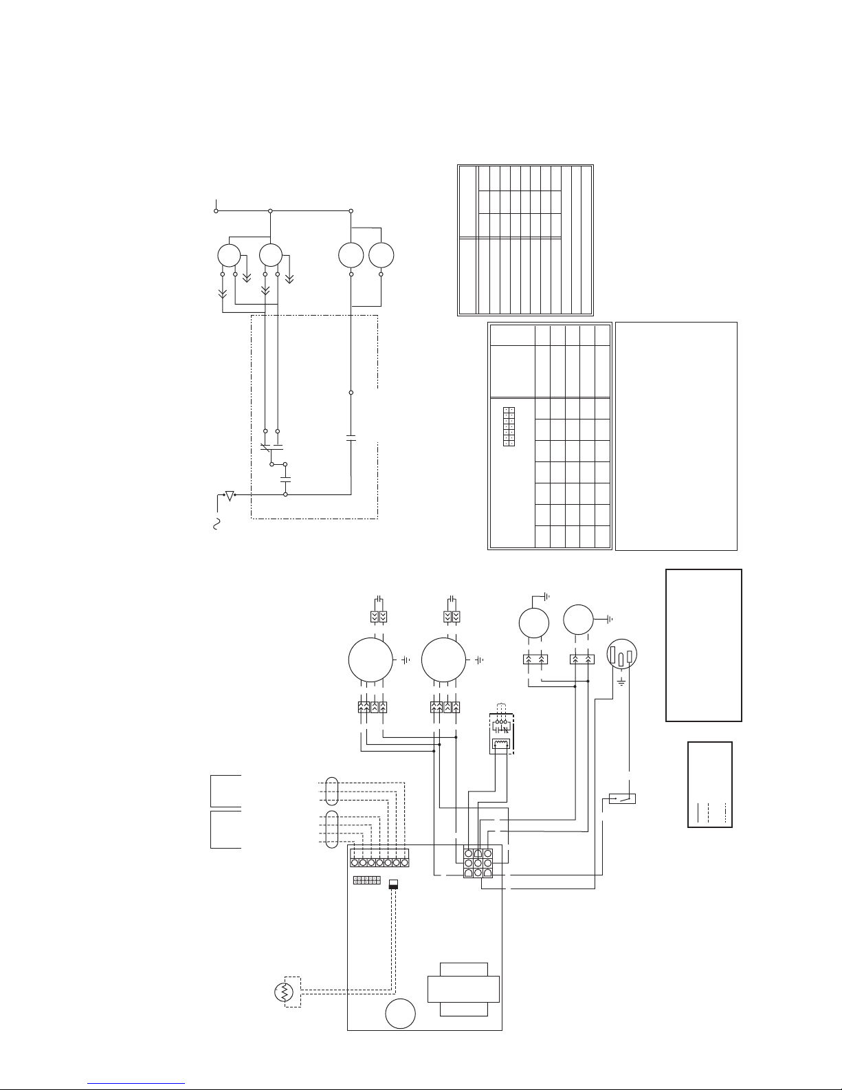
To ensure proper operation of ERV, configuration jumpers are
located on electronic control board and must match configuration
setup shown on Fig. 16 under Jumper Table. Jumpers are factory
set and do not require any changes unless control board is replaced.
If control board is replaced, or unusual start-up operation is
encountered, check jumpers to make sure they are located properly
(See Fig. 16).
II. DEFROST
Defrost cycle is controlled by a thermistor which is located in the
fresh-air intake passage (the thermistor unit is connected to J4 of
control module (See Fig. 16). When defrost temperature sensor
detects the need for defrost, K5 relay will close for 6 minutes while
K1 and K2 remain energized.
This closes the outdoor air damper while running ERV blower on
high-speed. This process recirculates warm indoor air through heat
recovery core which melts any frost that has formed. Water created
in this process is collected by ERV and drained away. Frequency
of the defrost cycle depends on outdoor temperature (See Table 3).
III. OFF AND INTERMITTENT/OFF MODE
Whenever ERV is off, K1 relay is open (See Fig. 16).
IV. HIGH-SPEED AIR EXCHANGE
When high-speed air exchange occurs, K1 relay closes and K2
(12–vdc relay) is energized. This breaks low-speed contacts, and
closes high-speed contacts. Then, 115vac is applied between
orange and grey wires on Molex plug (pins 1 and 6) and motor
runs in high-speed operation. Also, 115vac is applied across pins
5 and 7, this energizes interlock relay (See Fig. 16).
ELECTRONIC CONTROL
BOARD
OL
OC
I
J1
41 7
52 8
63 9
J3
9
8
7
THE WIRES FROM THE SWITCH
YELLOW – INDICATOR, (J3-3)
BLACK – COMMON, (J3-4)
RED – SWITCH, (J3-5)
6
5
4
3
(OPTIONAL)
60 MINUTE TIMER
(OPTIONAL)
PUSH BUTTON SWITCHES
(5 SWITCHES MAXIMUM)
RED
BLACK
YELLOW
(OC)
BLACK – (J3-4)
COMMON
TERMINAL
STRIP
YELLOW – (J3-3)
INDICATOR
TERMINAL STRIP
RED – (J3-5)
SWITCH
TERMINAL STRIP
BACK OF PUSH BUTTON SWITCH
Fig. 11–Push Button Timer Layout
—8—
(I)
(OL)
A98386
Page 9
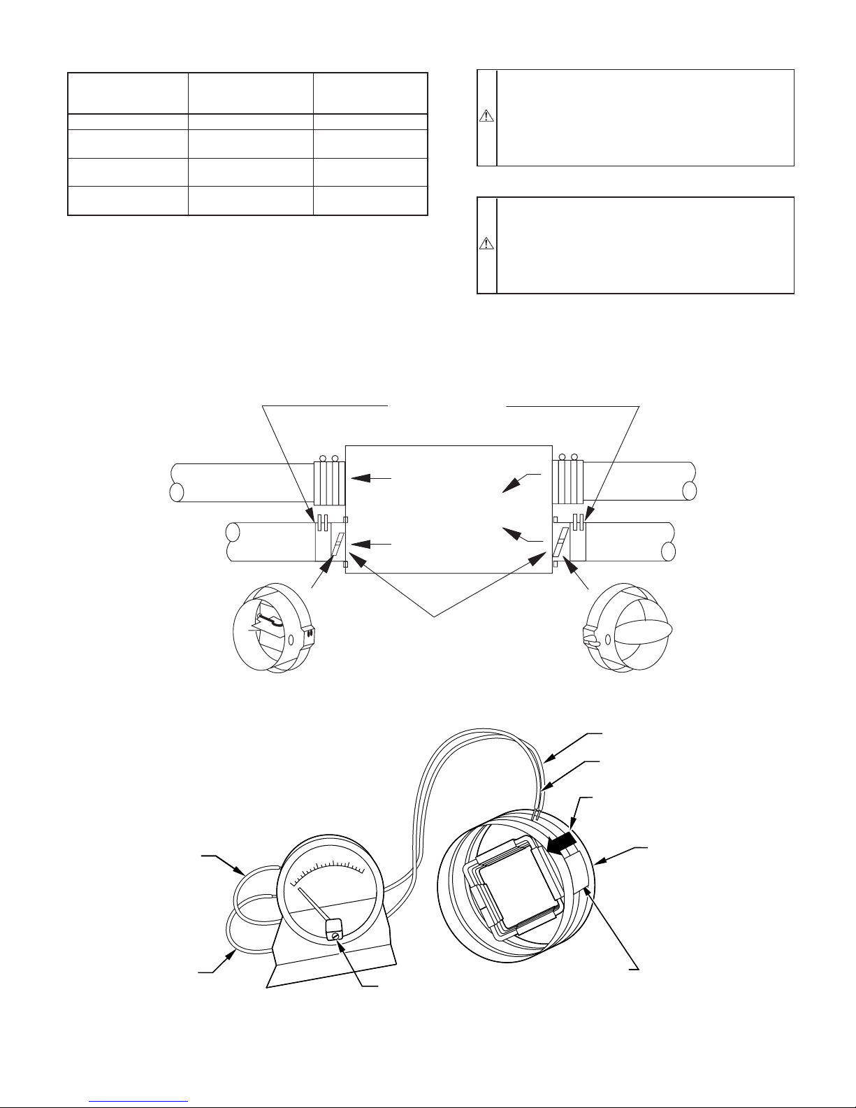
TABLE 3–DEFROST CYCLE
OUTSIDE TEMPERA-
TURE °F
Above 23°F No Defrost No Defrost
23°Fto5°F
4°F to -17°F
Below -18°F
STANDARD DE-
FROST (AS SHIPPED)
6 Minute Defrost/60
Minute Exchange
6 Minute Defrost/32
Minute Exchange
6 Minute Defrost/20
Minute Exchange
EXTENDED DE-
FROST (JUMPER
JU1-F REMOVED)
10 Minute Defrost/30
Minute Exchange
10 Minute Defrost/20
Minute Exchange
10 Minute Defrost/15
Minute Exchange
V. LOW-SPEED AIR EXCHANGE
When low-speed air exchange occurs, K1 relay closes and K2
(12–vdc relay) is de-energized. This keeps low-speed relay contacts closed and high-speed contacts open. Then, 115vac is applied
between red and gray wires on Molex plug (pins 1 and 4) and the
motor runs in low-speed operation. Also, 115vac is applied across
ins 5 and 7, energizing interlock relay (See Fig. 16).
CARE AND MAINTENANCE
WARNING: ELECTRICAL SHOCK HAZARD
Failure to follow this warning could result in personal
injury or death.
Before installing or servicing system, always turn off
main power to system. There may be more than 1
disconnect switch.
CAUTION: CUT HAZARD
Failure to follow this caution may result in personal
injury.
Sheet metal parts may have sharp edges or burrs. Use care
and wear appropriate protective clothing and gloves when
handling parts.
TEMPORARY
FLOW COLLAR
STALE AIR
TO OUTSIDE
FRESH AIR SUPPLY
TO BUILDING
→
MAX
BALANCING
DAMPER
Fig. 12–Balancing ERVBBLHU
MAX
MIN
AIRFLOW
DIRECTION
FLOW
COLLAR
FRESH AIR
FROM OUTSIDE
STALE AIR RETURN
FROM BUILDING
A05043
MIN
ZEROING SCREW
Fig. 13–Magnehelic Gage
—9—
CONVERSION
CHART
A98400
Page 10
STALE AIR
TO OUTSIDE
FRESH AIR
FROM OUTSIDE
FRESH AIR
TO BUILDING
Fig. 14–Airflow During Exchange
I. DOOR
ERV door can be removed by unlatching brief case style latches,
then lifting door up and sliding it sideways (See Fig. 17). Door
must be in place and secured shut for proper operation.
II. FILTER
Filters in ERV are washable and should be cleaned every 3
months. Use a vacuum cleaner to remove heaviest portion of
accumulated dust, then wash in lukewarm water. Allow filter to
completely dry before re-installing. A dirty air filter will cause
excessive strain on the blower motor. Never operate unit without
a filter (See Fig. 17).
In addition, regularly check and clean screens on exterior intake
and exhaust hoods when necessary.
CAUTION: UNIT COMPONENT DAMAGE HAZARD
Failure to follow this caution may result in unit component damage.
DO NOT clean filters in a dishwasher and DO NOT dry
them with a heating appliance or permanent damage will
result.
III. BLOWER MOTOR AND WHEEL
ERV blower motors are factory lubricated for life. Lubricating
bearings is not recommended. However, inspect and clean any
accumulated dirt and grease from blower motor and wheel
annually.
IV. CLEANING CORE
ERV is equipped with a special energy recovery core which is
made out of paper and allows transfer of sensible and latent
energy. The core should always be vacuumed only every 3 months
to remove dust and dirt that could prevent transfer of energy (See
Fig. 17).
NOTE: The core should only be serviced when outdoor temperature is between 60°F and 75°F and it is dry.
CAUTION: DO NOT use water to clean core or damage
will result. In addition, before servicing or removing the
core inspect the edges to see if they appear soft (or
slightly expanded). This can be normal and due to
moisture in the air. DO NOT handle or service core until
it is dry or air passages can become damaged and/or
closed.
STALE AIR
FROM BUILDING
A99269
TROUBLESHOOTING
WARNING: ELECTRICAL SHOCK HAZARD
Failure to follow this warning could result in personal
injury or death.
Before installing or servicing system, always turn off
main power to system. There may be more than one
disconnect switch.
CAUTION: CUT HAZARD
Failure to follow this caution may result in personal
injury.
Sheet metal parts may have sharp edges or burrs. Use care
and wear appropriate protective clothing and gloves when
handling parts.
NOTE: Reference Table 3 Troubleshooting Chart
This can be a quick guide in resolving unit problems. It is also
recommended to review and understand Wall Control Board
Operation and Care and Maintenance sections before continuing.
There are three main parts to focus on when troubleshooting ERV
unit:
1. Wall Control
2. Electronic control board
3. Blower motor
I. WALL CONTROL
Use Table 1 to determine if wall control is operating correctly. Use
Fig. 9 to check control wire connections.
NOTE: The electronic control board and wall control operate on
12vdc.
II. CONTROL BOARD
Electronic control board must have wall control attached before
unit will function properly. Also, configuration jumpers located on
control board must match configuration setup shown on Fig. 16
under Jumper Table. In addition, outside air thermistor must be
connected to control board for it to operate properly. See Table 4,
Temperature —vs— Ohm Chart, for valid temperature range.
III. BLOWER MOTOR
The ERV blower motor operates on 115vac, with 2–speed operation.
The easiest way to check blower speed operation is to use the wall
control and initiate a low-speed blower and high-speed blower
operation using intermittent mode (See Table 1, standard control
operation).
NOTE: If, after making the following test, you still hear relays
clicking upon charge, carefully check wiring, blower capacitor and
blowers.
Alternate procedure to check blower speed:
—10—
Page 11
MASTER
BEDROOM
WASH-
ROOM
#1
WASH-
ROOM
#2
BEDROOM
#3
LIVING ROOM
#6
WASH-
ROOM
#7
LAUNDARY
ROOM
#8
KITCHEN
#9
BEDROOM
BEDROOM
#4
1320 sq ft (125 sq m) 1320 sq ft (125 sq m)
#5
Fig. 15–Floor Plan Example
Blower Speed Test:
HIGH SPEED
1. Disconnect ERV from 115vac.
2. Unplug wall control wires at control module terminal block
inside ERV.
3. Plug ERV back to 115vac.
4. Attach a wire across J3–8 and J3–9 (B and G) on control
module terminal block.
5. Push in door switch. This will initiate a high-speed exchange.
LOW SPEED
1. Disconnect ERV from 115vac.
2. Unplug wall control wires at control module terminal block
inside ERV.
3. Plug ERV back to 115vac.
4. Attach a 3.9 K Ohm resistor between J3–8 and J3–9 (B and
G) on control module terminal block.
5. Push in door switch. This will initiate a low-speed exchange.
IV. BLOWER SPEED SELECTION
Three-speed blowers are factory connected to electronic control
board on HIGH and LOW speed taps of blowers. Installer can
easily change low-speed tap to medium-speed tap so electronic
control will select between high and medium speed. Connections
can be changed at motor location (See Tables 5 and 6).
To change low speed to medium speed, proceed as follows:
1. Unplug unit 115vac.
2. Remove filters and core from ERV.
3. Locate and remove wing nut on left side of unit.
4. Slide blower assembly to the right until wire connections
are visible.
5. Locate red wire and blue wire coming from blower assembly.
6. Unplug red wire from quick connect.
7. Unplug protecting cap quick connection from blue wire and
put on red wire coming from blower. The cap is a safety
insulator.
BASEMENT
1320 sq ft (125 sq m)
DINING ROOM
FAMILY ROOM
#10
#11
8. Connect red wire of main harness to blue wire.
9. Replace wires, blower assembly, filters and core.
a. OUTDOOR AIR THERMISTOR
When unit is not responding to wall control, check outdoor air
thermistor.
1. Remove thermistor wire from control board.
2. Take ohm reading across thermistor.
3. Refer to Table 4 for temperature/ohm relationship.
→
OPERATING THE ERV WITH THE EVOLUTION CONTROL
The ERV may be controlled using the Evolution system control.
The ERV may be connected using either a NIM or a 4-Zone
Damper Module. See the appropriate instructions if using the NIM
or 4-Zone Damper Module for connection instructions.
Blower interlock relay is not needed for use with the Evolution
system control. The Evolution system control will simultaneously
control the ERV and the indoor blower.
Push Button Timers may be used and are connected to the ERV as
shown in Figure 11. However, the Evolution system should be set
to continuous fan to ensure that the fresh air is circulated in the
home. In a Zoned System, at least one zone should be set to
continuous fan.
How does the ERV operate with the Evolution control?
The ventilator has four settings in heating mode and three settings
in cooling mode.
Heating:
AUTO - the ventilator selects the speed based on indoor
humidity and outdoor temp. It may cycle on/off every 30
minutes depending on humidity and outside temp.
LOW - low speed all of the time.
HIGH - high speed all of the time.
DEHUM - will only turn on if humidity is 3% over the
setpoint. The speed is determined by indoor humidity and
outdoor temp.
Cooling:
AUTO - the ventilator selects the speed based on indoor
humidity and outdoor temp. It may cycle on/off every 30
minutes depending on humidity and outside temp.
LOW - low speed all of the time.
HIGH - high speed all of the time.
A98388
—11—
Page 12
NEUTRAL
LOW
120VAC
J1 2
FAN
MOTOR
HIGH
DOOR
2
MED
(NOTE 5)
SWITCH
INTERLOCK
1001111
K5
0010110
J1 1
1
FAN
MOTOR
MED
(NOTE 5)
LOW
HIGH
J1 4
J1 6
K2
RELAY
K1
RELAY
J1 3
J1 8
MOTOR
DAMPER
1
J1 9
K5
2
MOTOR
DAMPER
CONTROL BOARD
RELAY
RELAY
FUNCTION TABLE
K2
K1
A
MODE
0111110
Intermittent
Exchange Low
Exchange High
Circulation low
Circulation high
Defrost Cycle
LETTER
TABLE
AAAAA
FUNCTION
MODEL
ERVBBSVU1150
2
1
IN
JU1G
ABCDEFG
JUMPER TABLE
JU1A JU1B JU1C JU1D JU1E JU1F
IN
IN
OUT
OUT
OUT
OUT
JU1
Off
0 = Relay coil is de-energized
1 = Relay coil is energized
ERVBBSVU1200
ERVBBLVU1150
INININ
INININ
INININ
OUT
OUT
OUT
OUT
OUT
OUT
OUT
OUT
NS = Not supported
ERVBBLVU1200
OUT
OUT
OUT
OUT
ERVBBLVU1330
IN
IN
IN
OUT
OUT
OUT
OUT
NOTES
A05068
AND ERVBBLVU1330.
2 - FAN MOTOR 2 IS USED ONLY WITH ERVBBLHU1250, ERVBBLVU1200,
ERVBBLVU1330.
3 - DAMPER MOTOR 2 IS USED ONLY WITH ERVBBLVU1200 AND
1 - THREE CONTROLS AVAILABLE. SEE THE INSTALLATION MANUAL
(LOW VOLTAGE ONLY 12 VDC).
LOW. MEDIUM SPEED CAN BE SELECTED INSTEAD OF LOW SPEED.
DISCONNECT RED WIRE FROM MOTOR(S) RED TAP AND CONNECT TO
4 - IF ANY OF THE ORIGINAL WIRE, AS SUPPLIED, MUST BE
MOTOR(S) BLUE TAP.
REPLACED, USE THE SAME OR EQUIVALENT WIRE.
5 - FACTORY SET WIRING FOR BLOWER SPEED SELECTION IS HIGH AND
OPTIONAL
NOTE 1
CONNECTION DIAGRAM LOGIC DIAGRAM
-t
DEFROST
TEMPERATURE SENSOR
MOTOR
CAPACITOR
NEUTRAL
HIGH
MEDIUM
FAN MOTOR 2 (NOTE 3)
OO
BLBNGY
1
2
NC
GY
OVERRIDE LED (YELLOW)
OVERRIDE SWITCH (BLACK)
OVERRIDE SWITCH (RED)
WALL CONTROL (YELLOW)
WALL CONTROL (RED)
WALL CONTROL (GREEN)
WALL CONTROL (BLACK)
1
2
BN
LOW
R
R
ABCDEFG
JU1
BLACK
BLACK
GREY
ORANGE
BKBLGYOG
RED
VIOLET
WHITE
YELLOW
RVWYBN
LINE VOLTAGE
LOW VOLTAGE
AND FIELD WIRE
GREEN
BROWN
NO CONNECTION
NC
OPTIONAL
Fig. 16—Wiring Diagram for Model ERV
24 VAC TO
INDOOR
(OPTIONAL)
TO J1 PIN 7
TO J1 PIN 5
Y
BL
9
6
3 2 1
(NOTE 4)
DAMPER MOTOR 2
Y
1
Y
EQUIPMENT
INTERLOCK RELAY KIT
O
BK
W
BL
2
NEUTRAL
W
COM
BK
120VAC 60HZ
NEMA-15P
G
LINE
BK
DOOR INTERLOCK SWITCH
COLOR CODE
NO
DAMPER MOTOR 1
Y
BL
2
1
BL
MOTOR
CAPACITOR
BN
BN
G
FAN MOTOR 1
1
J3
3 4 5 6 7 8 9
J4
NEUTRAL
HIGH
MEDIUM
O
GY
2
O
GY
GY
G
LOW
R
BL
NC
R
R
7
4
J1
POWER CONTROL BOARD
—12—
Page 13
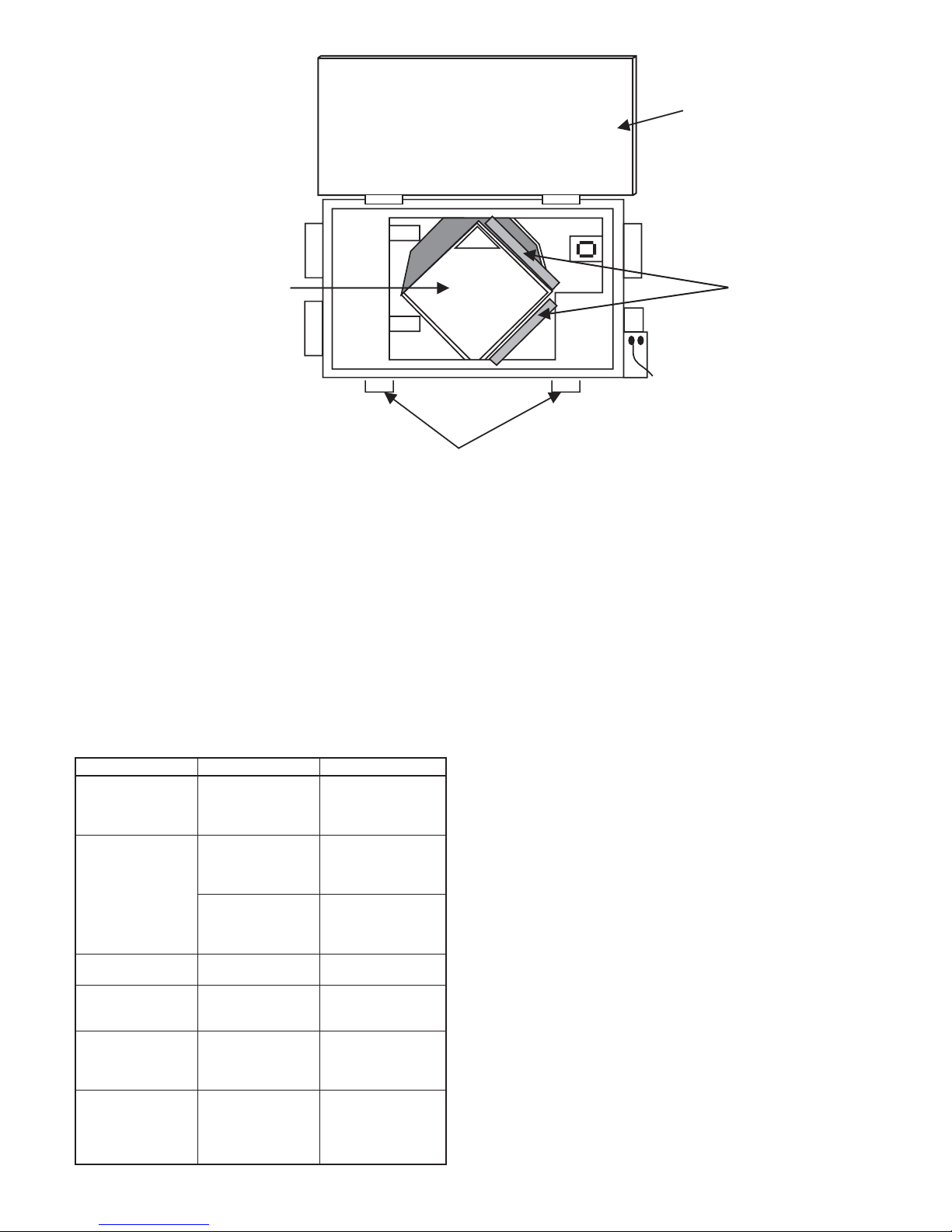
DOOR IS
DETACHABLE
ENERGY RECOVERY
CORE CAN BE REMOVED
BY PULLING STRAIGHT OUT
FILTERS ARE
REMOVABLE BY
PULLING STRAIGHT
OUT
BRIEF CASE
TYPE LATCH
A99300
Fig. 17–Energy Recovery Ventilator
TABLE 4–TROUBLESHOOTING CHART
SYMPTOMS CAUSES SOLUTIONS
Continous ex-
Air too humid
Unit not responding to
wall control
Unit stops momentarily
Air from distribution register
too cold
Unit makes annoying noise
Noise level too
high at distribution registers when in
high speed
hange mode
used in small
house
Is in defrost
Broken control
wire
Electrical supply
interrupted
Improper calibration of air
flow
Ventilation
wheel out of adjustment
Air duct system
too short
Use Intermittent
Mode Check
humidity level
settings
Wait until defrost has terminated, maximum
of 40 minutes
Test wall control, check connections, check
thermistor
Check units circuit breaker
Check calibration of flow rates
Remove the motor and screw
wheel on properly
Install a duct
silencer
—13—
Page 14
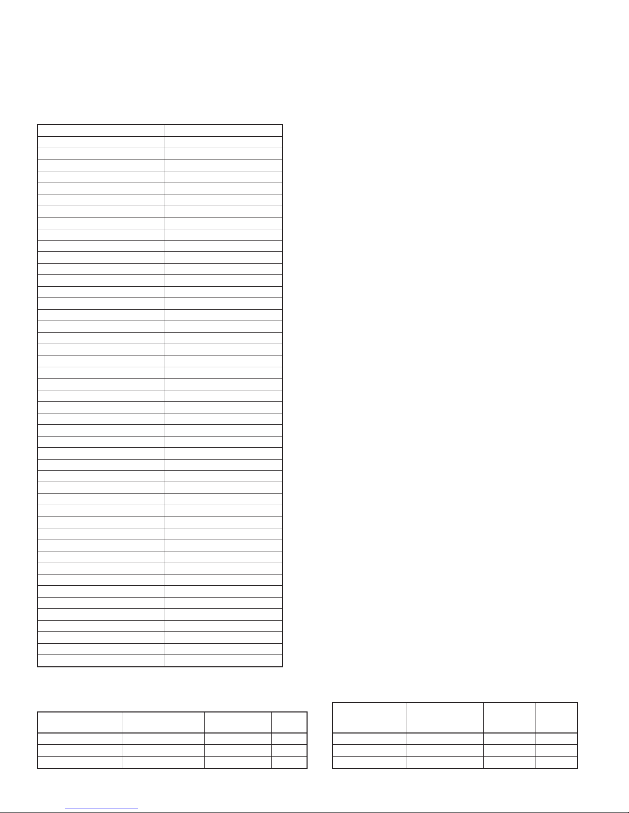
TABLE 5–TEMPERATURE/OHM RELATIONSHIP
TEMP F° OHMS
30 34,480
32 32,680
34 30,760
36 29,220
38 27,470
40 26,020
42 24,680
44 23,320
46 22,070
48 20,910
50 19,830
52 18,820
54 17,870
56 16,920
58 16,160
60 15,260
62 14,530
64 13,790
66 13,090
68 12,480
70 11,860
72 11,270
74 10,750
76 10,250
78 9,750
80 9,300
82 8,840
84 8,432
86 8,042
88 7,668
90 7,310
92 6,993
94 6,661
96 6,368
98 6,085
100 5,811
102 5,571
104 5,313
106 5,088
108 4,869
110 4,660
112 4,450
114 4,268
116 4,019
118 3,918
120 3,750
TABLE 6–FACTORY SET BLOWER CONNECTION HIGH
OR LOW SPEED
CONTROL MODULE
J1-6 Orange Orange High
No Connection No Connection Blue + Cap Medium
J1-4 Red Red Low
MAIN ELECTRICAL
HARNESS CABLE
BLOWER WIRE SPEED
—14—
TABLE 7–MODIFY BLOWER CONNECTION HIGH OR
MEDIUM SPEED
CONTROL
MODULE
J1-6 Orange Orange High
J1-4 Red Blue Medium
No Connection No Connection Red + Cap Low
MAIN ELECTRI-
CAL HARNESS
CABLE
BLOWER
WIRE
SPEED
Page 15

—15—
Page 16

© 2005 Bryant Heating & Cooling Systems 7310 W. Morris St. Indianapolis, IN 46231
—16—
Printed in U.S.A. erv643 Catalog No. II ERV-64–3
 Loading...