

Page 1
S E P / 1 0 / 2 0 0 8 / W E D 1 1 : 3 2
UTC TECH PUB
F A X N o , 3 1 7 2 4 0 5 6 6 2
348
Installation Instructions
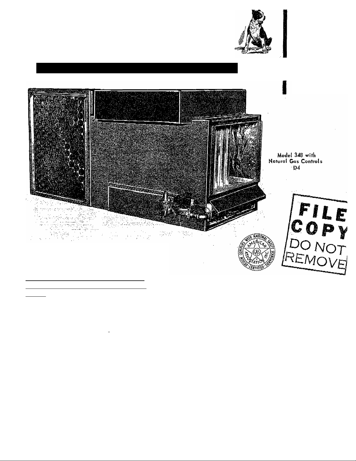
G AS-FIRED HORIZONTAL FURN ACE
Series E
39348D6 Rev 1
7/15/68 ^
The Bjjant Model 348 gas “fired forced air
horizontal furnace is certified by the Ameri
can Gas Association for attic installation .
Install in accordance with the requirements
of the local utility or authority having juris
diction.
The installer is referred to the American
Standard "Installation of Gas Appliances and
Gas'Piping, ASA Z21,30-1964, as a sound
and practical guide. ' . _ __
INSPECTION
—ühe .furnace ..is- ■ shippeiLwith -GOnt-rol-s -fully-
assembled. Note that natural gas units are
equipped with a combination regulator and
main manual shut-Off. As assembled, the
valve handle is on the underneath side. When
,1 handle is parallel with direction of gas floWj
the valve is open; when handle is at right
angles to direction of gas flow, the valve is
closed.
GAS CONTROL OPTIONS
D4 - Natural Gas
Bryant Gas Control Valve
Bryant Automatic Pilot
Combination Regulator, Main and
“ ■
.......
Pii ot ' Ga s S upplyV'àlvé s
D5 - Natural Gas - 10G% Shut-off
.....
-^'BryanrGas Control“Wiye^^''^—--------------------------
Thermocouple Automatic ^Piìot
-
-----
Pilot Gas Valve . \
Gas Regulator
Main Gas Shut-off Valve -
D2 - Propane Gas - 100% Shut-off
Bryant Gas Control Valve
Thermocouple Automatic Pilot /
Pilot Gas Valve
Main Gas Shut-off Valve
..- -
----------
Page 2
S E P / 1 0 / 2 0 0 8 / W E D 1 1 : 3 3
UTC TECH PUB
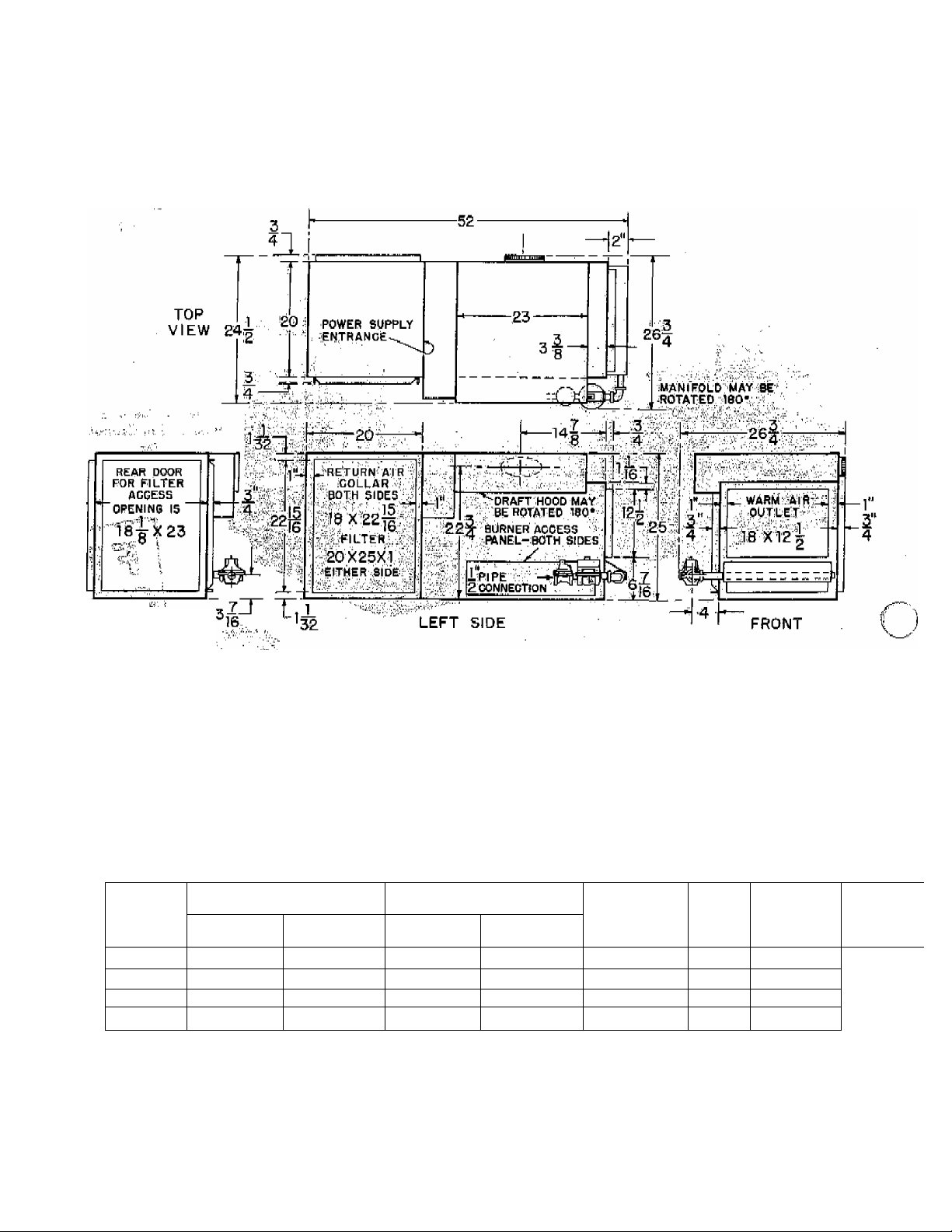
DIMENSIONS
3 1 7 2 4 0 5 6 6 2
..
w '-ilii. 'ii.' i:i
i-
REAR
■■ All-siK;es have the same dimensions.
:! ’iiOTvEii' Flue is 5" for sizes SO & ilDO; ■ ^ ■
;. v - Flue is 6" for size 125 & 145. ^ ■
R A TIN OS AN D CAPACIT | E 5
-l-f-l
-1-
pW,-, ,
AGA RATINGS* BTU/HR
MODEL
NO;
”8Ti:a^ “^^647000^
. 100-348 I0i);000 ' j
42S-348- _..435_000^-^
145^348
*Pot elevations Up to 20Q0 ft; fori higher altitudes, reduce mtingh 4% ier:e&ch;;.lGQD^ft. above sea level.
tOn size l45 permanent type filter is supplied as standard equipment. :‘See note cotidaming ait flow under
Table II, this iristfucUon. . /'■
INPUT OUTPUT' ,
. :80;000 ■ 1/2 1/2
■—iOOjDOO,-:-
145,000 , 116; 000 1/2
GAS CONNECTION SIZE :
NAT. PROP.
"■ 172 . -
------
iy_2—. .
■—^/2'
- ¡1/2 ¡.
BUilT-lN ^
FILTER
^2tT^':25jt;T^"
20 X 25 X 1
-20 3t 1-^ .i‘ .
^20 X 25 -x^il T:
FLUE
SIZE
■^■'5
5 175
.:■■■ 6
SHIPPING
---
.......
APPROX.
WT.
rers”
185 .—
185
■ 34S
- 2 -
Page 3
SE P / 10 /2 0 08 / WE D 11 : 33 AM UT C T E CH PU B
F AX N o . 3 1 7 2 40 56 6 2
P . 0 03 / 00 8
SPECIAL LOCATING INFORMATION
Also see the following section on mounting
the unit.
For special cases, refer to paragraphs 3 .4.2
and 3.4.3, American Standard "Installation of
Gas Appliances and Gas Piping, " ASA Z21,30
-1964.
1. Do not install unit in closet or alcove,
2. A,G.A, certified clearances from com
bustible material:
Attic Furnace
From Draft Diverter 6" *
From Casing Surface Line Contact Allowed
From Base > Ú"
*When the furnace is mstalled in ^space large
in comparison to the furnace, reduced clear
ances are permissible when combustibles in
question are adequately protected.. ^
3" clearance permitted when 28 gauge sheet
damper is in the full heat or full cool position
5 . The unit should be located centrally with
respect to the air distribution system .Choose
a location that will be as near the chimney as
possible.
6 . For flexibility in selecting location of unit,
the draft hood may be rotated 180 degrees.
The manifold may also be rotated 180 de
grees . The controls may then be on either
side of the furnace. They may also be in the
vertical plane “ leading up or down from the
manifold.
7. The wiring box is mounted externally
alongside the draft hood. The wiring box is
designed for field mounting on either side of
the unit without breaking wiring connections .
MOUNTING THE UNIT
The unit may be placed directly on a combus-
.■tible;.;^ clearance requirements listed
should be observed.
O
to '.'the cpihbusLible "^materialxíánd ; coyjsrsíiail
cómbus tibie;, .Wi'thih-;J5
Lë''''îhatéri^D' '■■is''"'àpplied' ■tb'’"the
material::and:;;covers all surfaces within 6".
Other methods of protecting the combustible
,materiail'.a37e!:.':,ide ,in-.,T®ë''!^Ô,''Îlme
'èÿnl;Stanfe of Gas Appliances
and Gras P.i;ping, " AsA Z2i .30-1964*
3 . Service Access; Leave as much clearance
ad^posd'ible for service. The following is
considered mihimum:' ■
■■ '25 ■’':'at filter ■ end 'to replace.;filtdr
!' 6" at top for cleaning heat exchanger
4. Location with respect to codling equipment:
pf ,th,e cooling .unit to; avoid condensation in
d'^e; furnace, beating lelement.. -When ..installed
■^arallel.^yitb'.a poping,unit,^da.mpcrs or,other
meani^ used to control the flow of air mast be
adequate ^ tp. prevenf chilled air from entering
the. furnace . If the, dampers are manually
operated, they must be equipped with means
to prevent operation of either unit unless the
............... ■
...
.................
rsf'oteG'-'fhb^^^'^^^ 348'Hs A ;G.A. certified for
,painf,;d2r';iii:ie A^fth C'ombustible mater
ial' abdye : ei^pept "drait hood must
, ,be ;at .least anyvcombusti^^^ material.
.Mpreifha^ dr ; line contact is not ap
proved.- ;If >an installation Gonflicts with
A*.G.A< ^PP^^'oval, consult .local codes for
protective insulation requirements. See
Ameri,cap Ap“
plianc.ea ;and Gas Fiping, ASA^Z2^
The draft hood may be reversed, The mani
fold may be reversed . The control's may be
horizontal or vertical. See page 4.
If the unit is mounted so as to require shims
^(uneven, floor ox-craWl .space.).it must be .S;tip-_
porfed as shown in Figtire A. "When unit Is
suspended, the same kind of supjiort is re -
_quire.d.,_Riy^nt,.s.upplles..asj0pfipnaiivd.quipb\bnt_.
a suspension kit hs picturedthTi^rd B. The
_two __ chahhels, should' be plhce d 'Under the :iur_-
nace as ■ shown in The .¡Support for
the blower comparftheht "Is fastened the
channel and theh bent abound htid fastened to
the other end of the ciiaiiiiel shoWii in Fig
ure C . This in effect mabes a support erfending out under the blower, compartihenb. Note:
the hanging rods for ttie suspension bars musi
be supplied by the installer. See page 5.
- 3 ^
348
Page 4

S E P / 1 0 / 2 0 0 8 / W E D 1 1 : 3 4 A M
UTC TECH PUB
1 , 3 1 7 2 4 0 5 6 6 2
P , 0 0 4 / 0 0 8
All i^electrical opi}neptions,,ar,e: ■.№
'he vh,';pérhi'ahent.i'liÿe.l:',iusèd;'èlectric'Circuit.P,;;
.....'.in'âiiüal;''7.S.witch ShòuÌ'd'.'he 'proyided.for this''..■ ' -:.".'/‘■■. a■
circuit. ^Üdnhêci-' iurh^^ 1X5 volt, ' 613
^;CÙrr e.nt .-power- ■ ■
.!p.üpplÿ;..,:F;or-Xuihia'ce^'';With';'-3j^.4''№
r: 230'Volt poorer süpply iis rëcDhiihè^ ,
¿The héat anticipatói: du.:thë№ogtat should Switch:
:'^'set"at'0,'8":àmpâ. ..'■.. /,.■ ^ . '.../.î::' „ , , i-.
I/-''
■■■■ "-■■ V. .■..., ' ■■’■■■ Thermodisc Auxiliary-ifLimifSwltch -
^T’U ^ Vu ^ ^ ■ _i-L __l"i J /'-L
The room tliermostat should be located where;
..
-it ■■ will-be in,,the- imturalOirdulatin^ path
room air : : Avoid locatiop^^^^ :therriip- ; : ; : /Limit Coutrdl ^ -i This control functions to shut
i .,i-.
£ ' ""qS, -the " gas :.ahd -cner^ze .the hlpwer motor if
¿drafta: frfapi; Windows, idpors.. or oth^r ippeh-:^ the fartiade hêchmhR teO.
; Xngs leading th
/Vhdrhónth,Xrom':^^i^rip ,prrègistars; or.
; to exposuró^y/hefè ih p',,,pa turai” òr
the air is cut off .such ,as behind doors, ahoyp
'br'helow mantels^ ;shelves/,btcr i ,'.:^,, , . ,,
The thermostat . should not bp exposed to heat
from , npapby . radiatb firèpïaces ; radios,
.¿kmps£.';:rays :.pf the :sh^ 'dier'“
miostat ;be . vm wail cbintainiiig pipes
0T. warm air ddhts,' 'or a fide or vënt which
__
____
_________
.'-'.V'. .^V. 'I ..'vr.o..Î. pvv. . .
còuld:, affèdtv its Ó,pe,ia4^^^^ It :fEom
'proï>ef |tSe' '-xOpm-' riempe rature .
Ànÿ.lioie in :^e'.plas^^^ which
thèritiûstat
:' COhITROLS;
N on -adjjuë table
' ^,e''¿.ecbhin;iende.d ^ of Checking the
-lini'it ' Vonthoi -isf .to '.^adda-iiy biôç;h“oÿ ■'the'-he-turh'':ai,r.,'aîtè,ï';^ 'lurna'cd'Ìia;s h'e.cn òpeXàtiiig
■for ..^n-pehipd'.of'àtTeastX 'rnihutéd .xAs''bqoÌi
a|; ‘the- ,Ximid;,ha'à.';proveh , 'the Tetdrh;'.aih
opening 'shòuld''hd uiiblochë'd 'to perdait normal
air circulation . Ëÿ dsiiig ibid hiethod tb-d^
the'"'iihiit control,''lt-';ca.n^ be bs'tdMdh'éd 'that
the limit is functioning properly and wall "fdil
safe" in case of motor failure .
_____
o
_
o
- 4 -
Page 5

S E P / 1 0 / 2 0 0 8 / W E D 1 1 : 3 4
UTC TECH PUB
1 , 3 1 7 2 4 0 5 6 6 2
P , 0 0 5 / 0 0 8
Controls L(contmuod) ‘ ' ■
t ^ \ . I'
The 348 Series E furnace is eqüípí|péd"^ án
adjustable fan'coiitrol switch/This confrdi^ i^
a single pole, single thrOw'íine voltage switch
actuated :by a heat motor.
The fan control adjusting lever is factory-set
at the center position and should give opti
mum . ,p^iformane^ ,íil, most,.,iiistallations..
dr' “^ere
:■ find'^vpiiige,, ■ as: cpnsid^
low báté¿l, output, it may be necessary to
increase " ol-tipap th^/.blower re -
maiptS Oh . Tor lOh^ operation, move
. adjh^iiig',le^
-■ ppsitip:^/;::^
switch'/^^^/^^ contact sooner pnd. ta^ea ^
ih^irhum time .to breaJk contact.;
“blower, operation, niov e: tlie lever .in Üié bp '
posite'■■direction.
Automatic Pilot r- Check the 'shut-off feature
of the automatic'pilot as follows; '
1. Spt the robin therimostat bn call for heat.
o
Bryant Qàs' 'Control Valve - if/not already
biiecked wjhéii lightitig the ^ ' checik;;
the' proper" operation of this Valve l^y moving
the room therinosm pointer abbye and
room temperature and- observe that the main
burners light on call foi heat and go off when
the pointer is moved below thé rooîn temper
ature.
'2. Close maiu manual gas shut-off valve and
the màhùàl pilot shut-off valve b ■
3 i pilot must break the eléctric circuit withiii
three ::m shut off. In the
case of tiië 100% shut-off contrcil, listen for
a click in the automatic shut-off valve. The
24rvolt circuit is not interrupted but the 100%'
shut-off valve should click within 3 minutés . \
- 5 -
348
Page 6

S E P / 1 0 / 2 0 0 8 / W E D 1 1 : 3 5 A M
UTC TECH PUB
Contrais (continued)
$lbwex'-ÁdjugFment - K blower speed is
not correct; the fan control switch may not
operate correctly. If an adjustable fan switch
is used with the unit, do not attempt to adjust
this switch iuntil the blower performance has
been checked ,;as described below,.
The temperature rise across the furnace
should be between 70F and 1Û0F . The blowers
are set .at, the factory to give approximately
85F temperature rise. Check this setting by
insertipg^. one thermometer in the return air
duct at the unit and another thermometer in
the plenum. Be sure the thermometer does
not ';see'^ the heat exchanger. The effect of
ráchaut heat will giv-e false readings. Allo^
:the unit to .Operate until the readipg^ on both :
di^rmòipetè have stabüii^çd. If the terobor.^fure ipise is too little or too greatf aidju^
blowerias described under section on blowers.
tdhder hp should the tempe'ra-^
'■ ture rise be allowed to exceed l'QQF'^.;.i:^j;;:i3::;c/^^^^
■ FI-LTEfîS
■ Qhe':x."'e 1 ■;-lithr0W'"a^ayi.l^p,^;iisu ^'■■ii
witii sizehhnd..125 permanent
f'iiter'/is-hu^^lie -the
F A X N0, 3 1 7 2 4 0 5 6 6 2
Color Code for .Speed
Common (white) ....
Hi Speed (black) ....
Med Speed (blue) ....
Med Lo Speed (yellow) - .
Lo Speed (red) .....
Important: It should be noted that air delivery
rate will vary with applied voltage at the
blower motor. If there ie any doubt about the
value of fluctuation of the supply voltage,
consult your local electric utility.
Belt Ptive
■The >125 and l4S'V3izes bel-t ,;drive units are
e^uii^ed'.w^ motors, wired at
the.factory for a 220rVOit power :Supply,. They
may be re-wif%dAih the
field for 115-volt
operation. See .wiping *
;.;. Tde;/id^ .at the factory
;is ;2^i>^2 ;:thr:h;s will provide
4pproximately:;i2i6p a
" ES:th;tic: ';p2:ess,ur^ .At thls setting
:the;^ , heat ex -
■■,cha:ngex-;ih.;''7,3,:7degrees{'F 1,25 and
. 85 idegrees F for/f^^
#C tap
#1 tap
#2 tap
#3 tap
#4 tap
Adjüstrn ',QÏ,'Biôwe r ,'Sp ëéjd^'” .7
To change "motor a pe e d: ;fap s > ' Tem òvè'the ■ mo ^ "
, ■, tor tap úleád, 'and relocate,; it,;¡Oñ;^;^ :¿,,
/ terminal' on ttie plugTn terminal block/speed
selector located in the.blower compártmeñt.'
■■ .See table '■ '''' ' '
■ ^ Cauiion: , When iádjusúiig 'iEi“"blowëiFTupeed'
'{ make ceÍTáin thoTeippera ri^e,acrpes the
ÿ heat /exchun^èr ;doés not {éxcoed'^ât .sp-^ified
:■ / On -the'■ratiiig^late.'""''^'''’'™■■■■
.Hêqt'ing type '*w* ■
Conpçc.t niotor Teod:
Size HP /;;■ '{//. ,.
80
1/8 y,eUow tap'3' ■■
80 ;
1/4:
100
1ÒÓ ■
125 i
145', 1/3
348
bláclcTáp 1
■1/8,1
„, f,., -Ï—fi——~—^—i”
i/3,
1/3^
■ M ëH'tJ irg/.C5 51 i rïg tTP
. iCóhn&ct m^tor lead; '
Heatjng
red 'tap 4 ' 'black'f’ap 1
,:"E. "
"'yellow tap 3 ' black tap 1
yelloiv tai¿) '3 black tap 1
biuie t^p 2 '
Cooling
Ì'. ■
■■ ■■■ '■
black tap 1
.If it; ^0 lehaiige /the' air delivery
rate:;,', .islihplyvdodseh'.:..!^ .iS.crew with an
' Alien ''Wi)^ehcH'i /the/''adjustable haK of
th.e-:Thi^l®WT to doge and counterc/io cJbivis e' /t9.; ;o;peh .■ ■ (/Jnc e ,pp sitione d, , .tighten
;::iihe'■ sc'reW''Oh'the'■ Tlat ; ■;a;,,
i l V U (M5TALL1HG :
The.furnace is factory agsembled. The order
_ .to hd: idUdwc.d in .setting ;thp. unit_iri plac.e^^^
making all hecessaa^ e onnedH (gas, elec trie,/VentihgA/ductwork, ^,e ie left to the
_h.ie Cretion /of the installeri. Recommendations
listed: on/ of this instruction
'SilpUld. he followed.. Connection to .gas{main________
supply ik"made,wi^ .supplied 1^ in
staller:..,. Wiring; .shpuld he . acc omplished ip
accordance with the applicable wiring dia
gram.. ' ■ .. '
„■■/"/ /.; t 1
B-cmember to check for correct wiring, on fhp
multi “tapped motors... in making up the low
voltage circuit on 100% shut-off controls, the
thermocouple pilot and automatic shut-off
- 6 -
Page 7

S E P / 1 0 / 2 0 0 8 / W E D 1 1 : 3 5
UTC TECH PUB
F A X N o , 3 1 7 2 4 0 5 6 6 2
valve are independent of the 24-volt circuit.
The ehippitig bolt should be removed from the
belt drive blower in accordance with label in
structions on the blower.
Remove the burner shipping wire after the
furnace has been set in place. It is recom
mended that flexible fireproof connections be
made from the unit to ductwork. Insulate all
ducts in attics and other cold areas .
CLEANING THE FURNACE
Burner shipping wire should have been re
moved when furnace was first installed.
1. Shut off all electric and gas supply to the
furnace.
2. Remove burner access panel (2 screws).
There is a panel on each side; either or both
may be used ,
3. The burner with pilot is located on either
the left or right end of the manifold.
After removing either or both..side access
panels* the burners may be removed in any
order with the burner with pilot being re
moved first or last.
a. Burners that dp not have the pilot at^
tached;
a-1. Lift upward out of back holding
slot-
a ^2. Piish burner to rear to disengage
/■ X\7f ^ ■
' ' ";a-3'.''Withdm through access
................. '^'opening.
b . Burners that have, the pilot attached:
_7A.A7b.-T < Цíacdhh.¿cf:
. ■ ; by removing wire nuts, Tbis ap-
' A fplies only fo Biyaht pilot. -.
—; "'-bT:2'i DiscohneC,t“^ilot■^gas■-^:Supply--m^
7' /y'aT,the .pilot valve
' ' . ,w,
.........
AA5_'
b“3. Straighten all tubing disconnected
in (2) above so that it sticks
strai^t out towards the manifold
end of furnace,
b-4. Lift burner upwards out of hold
ing slot* disengage from mani
fold spud, and then rotate the
burner with attached pilot and tub“
ing So that the pilot is on the top
side.
b“5. Remove entire assembly through
the access opening.
4. Disconnect vent pipe at draft hood.
5. Remove draft hood assembly.
6. Remove flue baffles from heat exchanger.
7. Use a flexible handled steel cleaning brush
to loosen scale and soot. Remove these
scrapings from bottom of combustion cbam-
ber.
8. ,Re-assemble furnace.
CARE AND MAINTENANCE
Care of Blowers: Motors on the belt drive
blowers are provided with oil wells, and
should be oiled at least twice a year with a
good grade of SAE 30 oil, The motors on the
direct drive blowers are sealed units and do
not require the addition of oil.
Blower. beaH semiApeirmhnentiylufei^^ :
cated'. ;;A^^ is normally good for
3 to .S .years-.--'-TOien necessary to add lubri
cant, use ''Culf Plastic E".
Filters should he examined f re -
■“qU!^ntly“^pr^,elpgging-^due to dirt-.---The dispo;^ —
able filters' ¡should'be replaced when they become ;dji:ty;,i;.pem type filters may be
-eleaned-using"-oiea'r-'Water-;-eoat-"the^-^^^
Water 3 olublf;; 6 il afte r cleaning. '
—■ Biscohhkit-pilotvbiee
■ 'Biyant valve.
. ■
......
On ip0%5 ilw-obf Apote
- disconnect thermocouple at auto
matic shut-off valve.
Cleaning"^: T^e heat should be ex
amined periodically to see if. th^3;e has been
an laccumuiatldn of rust, soot* etc . Clean as
required.
- 7 -
348
Page 8

S E P / 1 0 / 2 0 0 8 / W E D 1 1 : 3 6
UTC TECH PUB
F A X N o , 3 1 7 2 4 0 6 6 6 2
HEATING ONLY with ON-OFF FAN - Model 885 Thermostat P/N 34427D33 OR Thermostat P/N 34427D35 with
Sub-base P/N 34427D36*
 Loading...