

Page 1
DELUXE 14 SEER
AIR CONDITIONER
WITH PURON
TM
Bryant’s 556A with Puron
unmatched by any other family of equipment. The 556A is an
air conditioning system utilizing Bryant’s Puron refrigerant.
The environmentally sound refrigerant allows you to make a
responsible decision in the protection of the earth’s ozone
layer. Bryant’s 556A system with Puron refrigerant meet the
Energy Star® guidelines for energy efficiency.
®
Puron
refrigerant designed to help protect the environment. Puron
is an HFC refrigerant which does not contain chlorine that
can harm the ozone layer. The most impor tant advantage of
Puron refrigerant is that it has not been banned in future air
conditioning systems as the traditional refrigerant R-22 has
been. Puron refrigerant is in service in thousands of systems
proving highly reliable, environmentally sound performance.
Bryant’s Evolution™ Controls
controls, when installed with Bryant’s Perfect Humidity™
variable-speed furnaces or fan coils, provide the homeowner
with:
–unparalleled control of temperature, humidity, indoor air
quality, and zoning
–unprecedented ease of use
–simple operation through on-screen, text-based service
reminders
Optional remote access through telephone or Internet is also
available when combined with a remote connectivity kit.
Environmentally Sound Refrigerant
®
refrigerant provides features
FEATURES
—These industry-leading
®
REFRIGERANT
—Is Bryant’s
556A
Sizes 024 thru 060
Heavy Duty Inlet Grille
made of a coated steel wire grid with vertical 3/8 in. spacing,
is designed to help protect the coil from inclement weather,
vandalism, and incidental damage. It provides protection
while not restricting airflow and maintaining ease of coil
inspection and cleaning.
High Efficiency Performance
bination of features including Bryant’s Puron refrigerant,
scroll compressor, and adv anced heat transfer surfaces. Efficiency ratings are 14 SEER (Seasonal Energy Efficiency
Ratio) with enhanced ratings of up to 15.75 SEER. Sophisticated heat transfer surfaces utilized in Bryant’s 556A design
allow heat to easily be transferred to the outdoor air and
require less energy. The scroll compressor found in the 556A
design performs quietly and adds to the overall efficiency of
the system. The efficiency levels provided by the 556A provide end users with lower costs of operation than traditional
air conditioning systems.
Assured Future Service
sound refrigerant, Puron, 556A models will remain serviceable well into the future. The Clean Air Act of 1990 has
placed a cap on production of most other refrigerants which
has scheduled reductions beginning in 2004. The resulting
cap in production ultimately results in a complete ban on
many other refrigerants in new equipment by the year 2010.
These changes, required by federal law, mean the supply of
other refrigerants may be limited in the near future making
Puron the correct choice when considering long term serviceability.
Highly Reliable Performance
superior design of the system and componentry. The reliability of the 556A model has been proven to provide the
lowest incidence of warranty service of any product in the
Bryant family. Long term reliability is assured through the
use of both high and low pressure switches which will not
allow the system to operate in the event of a significant
change in operating pressure. In doing this, the system is
protected from damage if an unusual condition arises.
Finally, Bryant includes a special liquid line filter drier
designed to trap moisture and contaminants which could
otherwise shorten the life of the system.
Bryant’s AeroQuiet System
sound is the result of special attention to the air moving
through the outdoor unit, and a specially designed sound
enclosure surrounding the compressor to eliminate sound
transmission to the rest of the systems.
Application Versatility
refrigerant have the same application guidelines as other systems. Applications which include long line sets (50 to 175 ft)
—The DuraGuard™ coil protector,
—Is delivered through a com-
—By utilizing the environmentally
—Is delivered through the
— Extremely low operating
—Bryant systems utilizing Puron
Form No. PDS 556A.24.8
Page 2

or applications which require the system to operate at low outdoor temperatures (below 55°F) are approved under Bryant’s
standard guidelines.
Bryant Coils and Fan Coils to Complete the System
specially designs both the outdoor product and indoor coil products to operate with assured reliability and performance. A wide
range of indoor coil options are listed in the ratings section of
this publication.
Special Protective Devices
and internal protection in the compressor including temperature
and current sensing overloads prevent operation under potentially damaging circumstances. A special liquid line filter drier
designed to trap nearly 4 times the volume of contaminants of
standard driers provides superior protection from moisture
trapped in the system.
Electrical Range
Wide Range of Sizes
Cabinet
vide a superior, long lasting appearance.
—Galvanized steel is coated with powder paint to pro-
—208/230v, single phase.
—High and low pressure switches
—Available in six sizes; 2 through 5 tons.
—Bryant
Totally Enclosed Fan Motor
conditions.
Unit Design
surfaces with vertical air discharge to direct air up and away
from the area.
External Service Valves
type valves which are externally located. These unique valves
allow service technicians to evacuate or charge the system in
less time than standard service valves.
Easy Serviceability
both electrical and refrigerant carrying components simplifying
installation and service.
Agency Approvals
and Canada), ARI, and CEC. Special endorsements have also
been awarded these products by Energy Star® which recognizes energy efficient products.
Limited Warranty
and 5-year limited warranty on parts.
—Enhanced copper and aluminum heat transfer
—Removal of one panel provides access to
—556A models are listed with UL (U.S.
—A limited 10-year warranty on compressor
—Protected from adverse weather
—Both service valves are back seating
—2—
Page 3
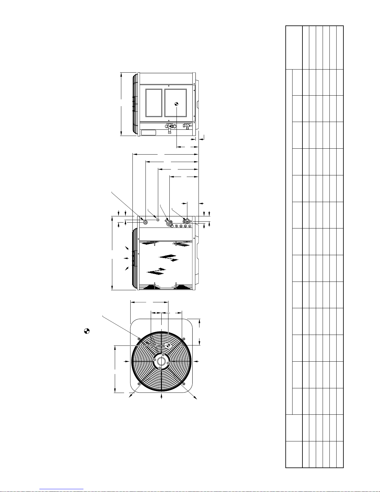
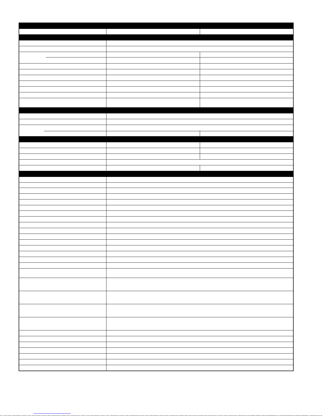
DIMENSIONS
MOUNTING
PAD DIMENSIONSABCDEFGHJKLMN
A97082
B
ACCESS
/8-IN. DIA
7
/8-IN. DIA KNOCKOUT
1
/8-IN. DIA KNOCKOUT
3
HOLE WITH 1
AND 1
FIELD POWER SUPPLY CONN
FIELD CONTROL
SUPPLY CONN
/16"
/2"
9
1
1
2
C
AIR DISCHARGE
PANEL
A
H DIA VAPOR
/8-IN. DIA HOLE
7
G
F
LINE CONN
/8-IN. DIA LIQUID
3
LINE CONN
/4"
1
1
M
/2"
1
10
/16"
3
/4"
3
4
1
N
UNIT DIMENSIONS MINIMUM
DIMENSIONS (IN.)
/8-IN. DIA TIEDOWN KNOCKOUTS
(2) PLACES IN BASEPAN
3
and 24 in. between units for proper airflow.
Minimum outdoor operating ambient in cooling mode is 55°F (unless low-ambient control is used) max 125°F.2.
Series designation is the 14th position of the unit model number.3.
1. Allow 30 in. clearance to service end of unit, 48 in. above unit, 6 in. on one side, 12 in. on remaining side,
Center of gravity .4.
AIR IN
L
NOTES:
AIR DISCHARGE
K
D
E
L
C
AIR IN
/16"
3
8
AIR IN
AIR DISCHARGE
SIZE SERIES
UNIT
024 G 33-13/16 30 33 5-1/16 9-11/16 27-15/16 34-3/8 5/8 8-3/16 16-3/4 19-1/2 15-3/4 2-15/16 26 x 32
030 F 39-13/16 30 33 5-1/16 9-11/16 27-15/16 34-3/8 3/4 8-3/16 16-3/4 19-1/2 17-1/4 2-15/16 26 x 32
036 F 39-13/16 30 33 5-1/16 9-11/16 27-15/16 34-3/8 3/4 8-3/16 16-3/4 19-1/2 17-1/4 2-15/16 26 x 32
042 F 39-13/16 30 33 5-1/16 9-11/16 27-15/16 34-3/8 7/8 8-3/16 16-3/4 19-1/2 17-1/4 2-15/16 26 x 32
048 B 39-13/16 30 33 5-1/16 9-11/16 27-15/16 34-3/8 7/8 8-3/16 16-3/4 19-1/2 17-1/4 2-15/16 26 x 32
060 A 39-13/16 38-5/8 42-1/16 7-1/8 12-1/8 27-15/16 34-3/8 7/8 8-3/16 19-7/8 26 17-1/4 2-15/16 35 x 41
—3—
Page 4
RECOMMENDED TUBE DIAMETERS
Liquid Tube Diameter (In.) Vapor Tube Diameter (In.)
UNIT
SIZE
024
0 to 50 Ft
Tube Length Long-Line Applications*
0 to 50 Ft
Tube Length
Long-Line Applications*
(Maximum Diameter)
5/8 3/4
030, 036 3/4 7/8
042 7/8 1-1/8
3/8 3/8
048 7/8 1-1/8
060 1-1/8 1-1/8
*For tube sets greater than 50 ft horizontal and /or 20 ft vertical differential, consult Residential Split System Application Guideline and Service Manual.
CHARGING SUBCOOLING (TXV-TYPE EXPANSION DEVICE*)
UNIT SIZE–SERIES REQUIRED SUBCOOLING (°F)
024-G 10
030-F 8
036-F 9
042-F 7
048-B 10
060-A 10
* Must be a Puron
®
approved hard shutoff TXV.
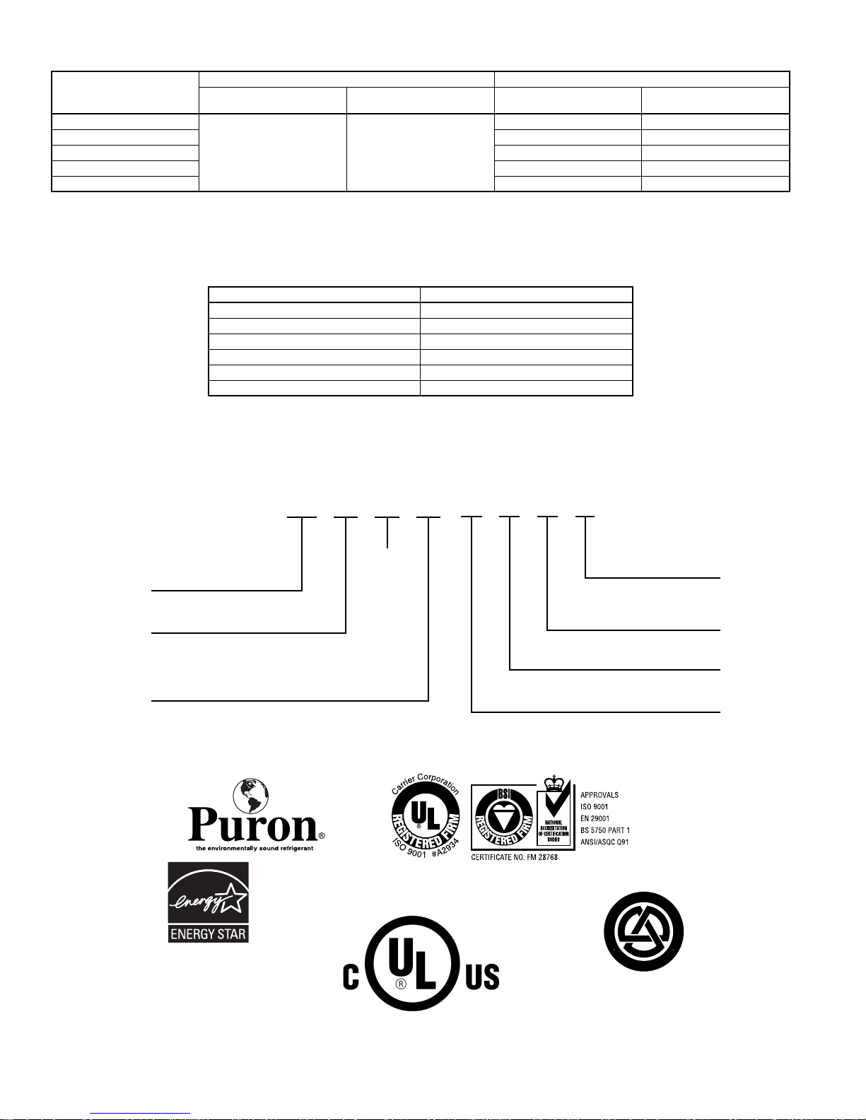
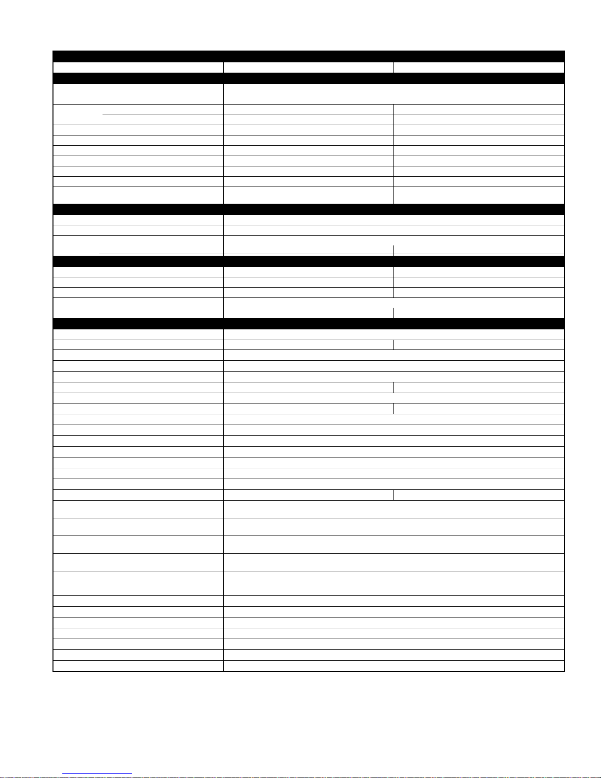
Model number nomenclature
556A N X 024
Model Number
14 SEER Split-System
Air Conditioner
Electrical Supply
N
– 208/230-1-60
Nominal Cooling Capacity
024
– 2 ton
030
– 2.5 ton
036
– 3 ton
As an ENERGY STAR
partner, Bryant Heating &
*
Cooling Systems has
determined that this product meets the ENERGY
®
STAR
guidelines for
energy efficiency.
042
048
060
®
– 3.5 ton
– 4 ton
– 5 ton
N/A
REGISTERED QUALITY SYSTEM
000 A A AA
Series A
Series B
Common Unit
Heating Size
CERTIFICATION APPLIES ONLY
WHEN THE COMPLETE SYSTEM
Standard Unit
– Original Series
– Second Series, etc.
– U.S.A. Only
T
O
D
E
A
I
R
F
I
I
T
A
R
S
E
C
R
E
R
U
T
C
A
U
F
U
N
A
M
A
R
C
O
A
M
I
R
C
P
O
Y
R
A
T
I
N
I
S
L
N
D
Y
I
T
I
N
I
O
G
N
I
N
W
G
I
T
E
T
H
T
Q
N
U
E
I
P
M
0
1
2
D
A
R
N
A
D
IS LISTED WITH ARI.
*Refer to the combination ratings in the Product Data Sheet for system combination meeting ENERGY STAR® efficiency standards.
—4—
Page 5
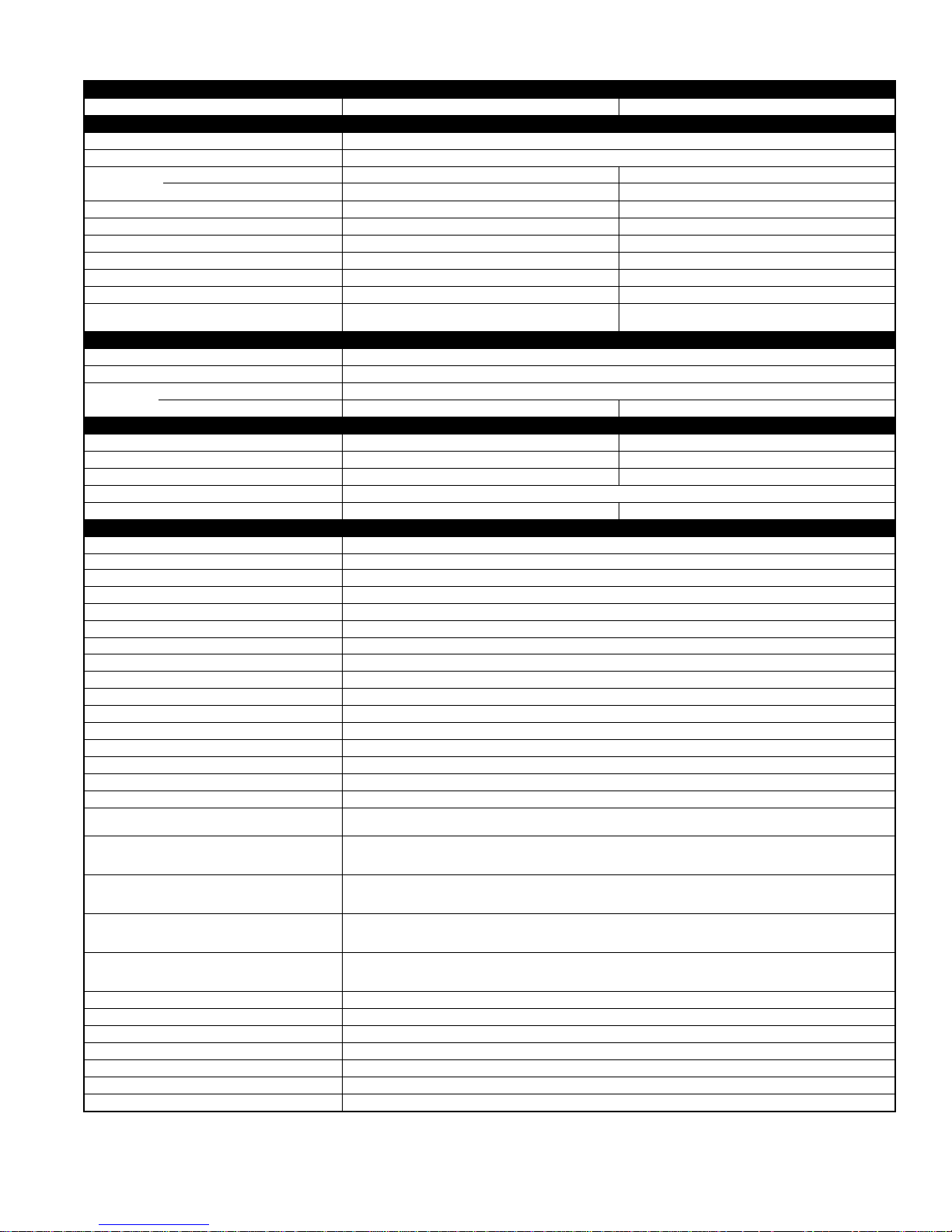
SPECIFICATIONS
UNIT SIZE-SERIES 024-G 030-F
Operating Weight (Lb) 284 284
ELECTRICAL
Unit Volts—Hertz—Phase 208/230—60—1
Operating Voltage Range* 187—253
Compressor— Rated Load Amps 12.8 14.7
Locked Rotor Amps 60.0 72.5
Condenser Fan Motor—Full Load Amps 0.80 0.80
Min Unit Ampacity for Wire Sizing 16.8 19.2
Min Wire Size (60°C Copper) AWG† 14 14
Min Wire Size (75°C Copper) AWG† 14 14
Max Wire Length (Ft) (60°C Copper)‡ 46 41
Max Wire Length (Ft) (75°C Copper)‡ 44 39
Max Branch Circuit Fuse or
Circuit Breaker Size (Amps) 25 30
COMPRESSOR & REFRIGERANT
Compressor—Type Scroll
Temperature & Current Protection Internal Line Break
Refrigerant—Type Puron® (R-410A)
Amount (Lb) 9.35 9.11
CONDENSER COIL & FAN
Coil Face Area (Sq Ft) 15.2 18.25
Fins per In.—Rows—Circuits 20—2—4 20-—2—4
Fan Motor—HP (PSC) & RPM 1/8 & 825 1/8 & 825
Volts—Hertz—Phase 208/230—60—1
Condenser Airflow (CFM) 2400 2400
OPTIONAL EQUIPMENT
Support Feet KSASF0101AAA
Coastal Filter KAACF0801MED
Time Delay Relay KAA TD0101TDR
Cycle Protector KSACY0101AAA
Crankcase Heater KAACH1201AAA
Start Assist—Capacitor/Relay Type KSAHS1501AAA
Start Assist—PTC Type KAACS0201PTC
TXV (Hard Shutoff) KSA TX0201PUR
Piston Body KSAPX0101PIS
Filter Drier (Suction Line) KH45LG140 (RCD)
Evaporator Freeze Thermostat†† KAAFT0101AAA
Liquid-Line Solenoid Valve KAALS0201LLS
Winter Start Control†† KAAWS0201AAA
Low-Ambient Pressure Switch KSALA0301410
MotorMaster®—Low-Ambient Controller** KSALA0401AAA
Ball Bearing Fan Motor HC38GE231 (RCD)
Thermidistat™ Control—
Programmable Thermostat with Humidity Control TSTATBBPRH01-B
Thermostat—Auto Changeover,
7-Day Programmable, °F/°C,
1-Stage Heat, 1-Stage Cool TSTATBBPAC01-B
Thermostat—Auto Changeover,
Non-Programmable, °F/°C,
1-Stage Heat, 1-Stage Cool TSTATBBNAC01-B
Thermostat-Manual Changeover
5-2 Day Programmable, °F/°C,
1-Stage Heat, 1-Stage Cool TSTATBBSAC01
Builder’s Thermostat—Manual Changeover,
Non-Programmable, °F/°C,
1-Stage Heat, 1-Stage Cool TSTATBBBAC01-B
Outdoor Air Temperature Sensor TSTATXXSEN01-B
Backplate for Non-Programmable Thermostat TSTATXXNBP01
Backplate for Programmable Thermostat TSTATXXPBP01
Backplate for Builder’s Thermostat TSTATXXBBP01
Backplate for Standard Thermostat TSTATXXSBP01
Thermostat Conversion Kit (4 to 5 wire)—10 Pack TSTATXXCNV10
Evolution Controls See chart
See notes on page 7.
—5—
Page 6
SPECIFICATIONS Continued
UNIT SIZE-SERIES
Operating Weight (Lb) 287 288
ELECTRICAL
Unit Volts—Hertz—Phase 208/230—60—1
Operating Voltage Range* 187—253
Compressor—Rated Load Amps 15.4 18.6
Locked Rotor Amps 83.0 105.0
Condenser Fan Motor—Full Load Amps 0.8 1.1
Min Unit Ampacity for Wire Sizing 20.1 24.4
Min Wire Size (60°C Copper) AWG† 12 10
Min Wire Size (75°C Copper) AWG† 12 10
Max Wire Length (Ft) (60°C Copper)‡ 62 81
Max Wire Length (Ft) (75°C Copper)‡ 59 77
Max Branch Circuit Fuse or
Circuit Breaker Size (Amps) 30 40
COMPRESSOR & REFRIGERANT
Compressor—Type Scroll
Temperature & Current Protection Internal Line Break
Refrigerant—Type Puron® (R-410A)
Amount (Lb) 9.83 9.66
CONDENSER COIL & FAN
Coil Face Area (Sq Ft) 18.25 18.25
Fins per In.—Rows—Circuits 20—2—4 20—2—4
Fan Motor—HP (PSC) & RPM 1/5 & 825 1/5 & 825
Volts—Hertz—Phase 208/230—60—1
Condenser Airflow (CFM) 2800 2800
OPTIONAL EQUIPMENT
Support Feet KSASF0101AAA
Coastal Filter KAACF0201MED
Time Delay Relay KAA TD0101TDR
Cycle Protector KSACY0101AAA
Crankcase Heater KAACH1201AAA
Start Assist—Capacitor/Relay Type KSAHS1501AAA
Start Assist—PTC Type KAACS0201PTC
TXV (Hard Shutoff) KSA TX0301PUR
Piston Body KSAPX0101PIS
Filter Drier (Suction Line) KH45LG141 (RCD)
Evaporator Freeze Thermostat†† KAAFT0101AAA
Liquid-Line Solenoid Valve KAALS0201LLS
Winter Start Control†† KAAWS0201AAA
Low-Ambient Pressure Switch KSALA0301410
MotorMaster®—Low-Ambient Controller** KSALA0401AAA
Ball Bearing Fan Motor HC38GE231 (RCD)
Thermidistat™ Control—
Programmable Thermostat with Humidity Control TSTATBBPRH01-B
Thermostat—Auto Changeover,
7-Day Programmable, °F/°C,
1-Stage Heat, 1-Stage Cool TSTATBBPAC01-B
Thermostat—Auto Changeover,
Non-Programmable, °F/°C,
1-Stage Heat, 1-Stage Cool TSTATBBNAC01-B
Thermostat—Manual Changeover
5-2 Day Programmable, °F/°C,
1-Stage Heat, 1-Stage Cool TSTATBBSAC01
Builder’s Thermostat—Manual Changeover,
Non-Programmable, °F/°C,
1-Stage Heat, 1-Stage Cool TSTATBBBAC01-B
Outdoor Air Temperature Sensor TSTATXXSEN01-B
Backplate for Non-Programmable Thermostat TSTATXXNBP01
Backplate for Programmable Thermostat TSTATXXPBP01
Backplate for Builder’s Thermostat TSTATXXBBP01
Backplate for Standard Thermostat TSTATXXSBP01
Thermostat Conversion Kit (4 to 5 wire)—10 Pack TSTATXXCNV10
Evolution Controls See chart
See notes on page 7.
036-F 042-F
—6—
Page 7
UNIT SIZE-SERIES 048-B 060-A
Operating Weight (Lb) 295 345
ELECTRICAL
Unit Volts—Hertz—Phase 208/230—60—1
Operating Voltage Range* 187—253
Compressor—Rated Load Amps 20.5 26.9
Locked Rotor Amps 109.0 145.0
Condenser Fan Motor—Full Load Amps 1.1 1.4
Min Unit Ampacity for Wire Sizing 26.7 35.0
Min Wire Size (60°C Copper) AWG† 10 8
Min Wire Size (75°C Copper) AWG† 10 8
Max Wire Length (Ft) (60°C Copper)‡ 74 89
Max Wire Length (Ft) (75°C Copper)‡ 70 84
Max Branch Circuit Fuse or
Circuit Breaker Size (Amps) 40 60
COMPRESSOR & REFRIGERANT
Compressor—Type Scroll
Temperature & Current Protection Internal Line Break
Refrigerant—Type Puron® (R-410A)
Amount (Lb) 12.00 15.00
CONDENSER COIL & FAN
Coil Face Area (Sq Ft) 18.3 24.5
Fins per In.—Rows—Circuits 20—2—4 20—2—6
Fan Motor—HP (PSC) & RPM 1/5 & 825 1/5 & 825
Volts—Hertz—Phase 208/230—60—1
Condenser Airflow (CFM) 2800 3800
OPTIONAL EQUIPMENT
Support Feet KSASF0101AAA
Coastal Filter KAACF0801MED KAACF0901LRG
Time Delay Relay KAA TD0101TDR
Cycle Protector KSA CY0101AAA
Crankcase Heater KAACH1201AAA
Start Assist—Capacitor/Relay Type KSAHS1501AAA KSAHS1601AAA
Start Assist—PTC Type KAACS0201PTC
TXV (Hard Shutoff) KSATX0401PUR KSA TX0501PUR
Piston Body KSAPX0101PIS
Filter Drier (Suction Line) KH45LG141 (RCD)
Evaporator Freeze Thermostat†† KAAFT0101AAA
Liquid-Line Solenoid Valve KAALS0201LLS
Winter Start Control†† KAAWS0201AAA
Low-Ambient Pressure Switch KSALA0301410
MotorMaster®—Low-Ambient Controller** KSALA0401AAA
Ball Bearing Fan Motor HC38GE231 (RCD) HC38GE232 (RCD)
Thermidistat™ Control—
Programmable Thermostat with Humidity Control TSTATBBPRH01-B
Thermostat—Auto Changeover , 7-Day Programmable ,
°F/°C, 1-Stage Heat, 1-Stage Cool TSTATBBPAC01-B
Thermostat—Auto Changeover, Non-Programmable,
°F/°C, 1-Stage Heat, 1-Stage Cool TSTATBBNAC01-B
Thermostat—Manual Changeover, 5-2 Day
Programmable, °F/°C, 1-Stage Heat, 1-Stage Cool TSTATBBSAC01
Builder’s Thermostat—Manual Changeover,
Non-Programmable, °F/°C,
1-Stage Heat, 1-Stage Cool TSTATBBBAC01-B
Outdoor Air Temperature Sensor TSTATXXSEN01-B
Backplate for Non-Programmable Thermostat TSTATXXNBP01
Backplate for Programmable Thermostat TSTATXXPBP01
Backplate for Builder’s Thermostat TSTATXXBBP01
Backplate for Standard Thermostat TSTATXXSBP01
Thermostat Conversion Kit (4 to 5 wire)—10 Pack TSTATXXCNV10
Evolution Controls See chart
*Permissible limits of the voltage range at which the unit will operate satisfactorily. Operation outside these limits may result in unit failure.
† If wire is applied at ambient greater than 30°C (86°F), consult Table 310-16 of the NEC (ANSI/NFPA 70).
The ampacity of nonmetallic-sheathed cable (NM), trade name ROMEX, shall be that of 60°C (140°F) conductors, per the NEC (ANSI/NFPA 70) Article 336-26.
If other than uncoated (non-plated), 60 or 75°C (140 or 167°F) insulation, copper wire (solid wire for 10 AWG and smaller , str anded wire for larger than 10 AWG)
is used, consult applicable tables of the NEC (ANSI/NFPA 70).
‡ Length shown is as measured 1 way along wire path between unit and service panel for a voltage drop not to exceed 2%.
** Fan motor with ball bearings required.
†† See low-ambient controller Installation Instructions for application.
N/A — Not Applicable.
NOTE:
Copper wire must be used from service disconnect to unit. All motors/compressors contain internal overload protection.
SPECIFICATIONS Continued
—7—
Page 8
EVOLUTION™* CONTROLS
DESCRIPTION ACCESSORY
Evolution Control Deluxe 7-Day Programmable (Wall-mounted system control.) SYSTXBBUID01
Evolution Zone Control Deluxe Zoning 7-Day Programmable
Z
(Wall-mounted control for a multi-zone system.)
O
Evolution 4-Zone Damper Control Module (Wall-mounted control for a four-zone system.) SYSTXBB4ZC01
N
I
Evolution Smart Sensor (Optional wall control used to monitor temperature
and/or fan control in an individual zone.)
N
G
Evolution Remote Room Sensor (Monitors temperature in an individual zone.) SYSTXBBRRS01
Evolution System Access Module
(Hardware for wireless access and control via phone or internet.)
Evolution Network Interface Module (Connects Heat Recovery or
Energy Recovery Ventilators or older two-speed outdoor models to system.)
Back Plate for Evolution Control (Decorative wall plate.) SYSTXXXBPU01
SYSTXBBUIZ01
SYSTXBBSMS01
SYSTXBBSAM01
SYSTXBBNIM01†
* When applied with Bryant’s Perfect Humidity™ series 355, 315 and FE Indoor Models.
† Must be installed in Dual-Fuel Evolution system applications.
ACCESSORY USAGE GUIDELINE
REQUIRED FOR
LOW-AMBIENT
ACCESSORY
Crankcase Heater Yes Yes No
Evaporator Freeze Thermostat Yes No No
Winter Start Control Yes† No No
Accumulator No No No
Compressor Start Assist—
Capacitor/Relay Type
MotorMaster® Low-Ambient Controller
or
Low-Ambient Pressure Switch
Wind Baffle See Low-Ambient Instructions No No
Coastal Filter No No Yes
Support Feet Recommended No Recommended
Liquid-Line Solenoid Valve
or
Hard Shutoff TXV
Ball Bearing Fan Motor Yes‡ No No
APPLICATIONS
(Below 55°F)
Yes Yes No
Yes No No
No
*For tubing line sets greater than 50 ft, refer to Residential Split-System Long-Line Application Guideline and Service Manual.
† Only when low-pressure switch is used.
‡ Required for low-ambient controller (full modulation feature) and MotorMaster® Control only.
REQUIRED FOR
LONG-LINE
APPLICATIONS*
(Over 50 Ft)
See Long-Line
Application
Guideline
REQUIRED FOR
APPLICATIONS
(Within 2 Miles)
SEA COAST
No
ACCESSORY DESCRIPTION AND USAGE (Listed Alphabetically)
1.
Ball-Bearing Fan Motor
A fan motor with ball bearings which permits speed reduction while maintaining bearing lubrication.
Usage Guideline:
2.
Coastal Filter
A mesh screen inserted under the top cover and inside the base pan to protect the condenser coil from salt damage without restricting airflow.
3.
Compressor Start Assist – Capacitor and Relay
Start capacitor and relay gives a "hard" boost to compressor motor at each start up.
Usage Guideline:
4.
Compressor Start Assist — PTC Type
Solid state electrical device which gives a "soft" boost to the reciprocating compressor at each start-up.
Usage Guideline:
Required on all units when low-ambient controller (full modulation feature) or MotoMaster®—Low-Ambient Controller is installed.
Required for reciprocating
Long line
Low ambient
Hard shut off expansion valve on indoor coil
Liquid line solenoid on indoor coil
Required for scroll
Long line
Low ambient
Suggested for all compressors in areas with a history of low voltage problems.
Suggested in installations with marginal power supply.
compressors in the following applications:
compressors in the following applications:
—8—
Page 9

ACCESSORY DESCRIPTION AND USAGE (continued)
5.
Crankcase Heater
An electric resistance heater which mounts to the base of the compressor to keep the lubricant warm during off cycles. Improves compressor lubrication
on restart and minimizes the chance of liquid slugging.
Usage Guideline:
6.
Evaporator Freeze Thermostat
An SPST temperature-actuated switch that stops unit operation when evaporator reaches freeze-up conditions.
Usage Guideline:
7.
Liquid-Line Solenoid Valve (LLS)
This device serves two purposes. It is an electrically operated shutoff valve which stops and starts refrigerant liquid flow in response to compressor operation. It maintains a column of refrigerant liquid ready for action at next compressor operation cycle. It also provides system protection against off-cycle
refrigerant migration.
Note:
When LLS is used with reciprocating compressors, Compressor Start Assist — Capacitor and Relay is required.
Usage Guideline:
8.
MotorMaster®—Low-Ambient Controller
A fan-speed control device activated by a temperature sensor, designed to control condenser fan motor speed in response to the saturated, condensing
temperature during operation in cooling mode only. For outdoor temperatures down to –20°F (–28.9°C), it maintains condensing temperature at 100°F ±
10°F (37.8°C ± –12°C).
Usage Guideline:
9.
Outdoor Air Temperature Sensor
Designed for use with Bryant Thermostats listed in this publication. This device enables the thermostat to display the outdoor temperature. This device also
is required to enable special thermostat features such as auxiliary heat lock out.
Usage Guideline:
10.
Sound Hood
Wraparound sound reducing cover for the compressor. Reduces the sound level by about 2 dBA.
Usage Guideline:
11.
Support Feet
Four stick-on plastic feet that raise the unit 4 in. above the mounting pad. This allows sand, dirt, and other debris to be flushed from the unit base, minimizing
corrosion.
Usage Guideline:
12.
Thermostatic Expansion Valve (TXV)
A modulating flow-control valve which meters refrigerant liquid flow rate into the evaporator in response to the superheat of the refrigerant gas leaving the
evaporator. Kit includes valve, adapter tubes, and external equalizer tube. Hard shut off types are available.
Note:
When using a hard shut off TXV with single phase reciprocating compressors, a Compressor Start Assist — Capacitor and Relay is required.
Usage Guideline:
13.
Time-Delay Relay
An SPST delay relay which briefly continues operation of indoor blower motor to provide additional cooling after the compressor cycles off.
Note:
Most indoor unit controls include this feature. For those that do not, use the guideline below.
Usage Guideline:
Required in low ambient applications.
Required in long line applications.
Suggested in all commercial applications.
Required when low ambient kit has been added.
Required in air conditioner long line applications with a piston indoor metering device to prevent off cycle refrigerant migration. A hard shut
off TXV can be used instead of an LLS in single flow air conditioner applications. See Long Line Application Guideline.
A MotorMaster®—Low-Ambient Controller or Low-Ambient Pressure Switch must be used when cooling operation is used at outdoor temperatures below 55°F (12.8°C).
Suggested for all commercial applications.
Suggested for all Bryant thermostats listed in this publication.
Suggested when unit is installed closer than 15 ft to quiet areas—bedrooms, etc.
Suggested when unit is installed between two houses less than 10 ft apart.
Suggested in the following applications:
Coastal installations.
Windy areas or where debris is normally circulating.
Rooftop installations.
For improved sound ratings.
Required to achieve ARI ratings in certain equipment combinations. Refer to combination ratings.
Hard shut off TXV or LLS required in air conditioner long line applications
Required for use on all zoning systems.
For improved efficiency ratings for certain combinations of indoor and outdoor units. Refer to ARI Unitary Directory.
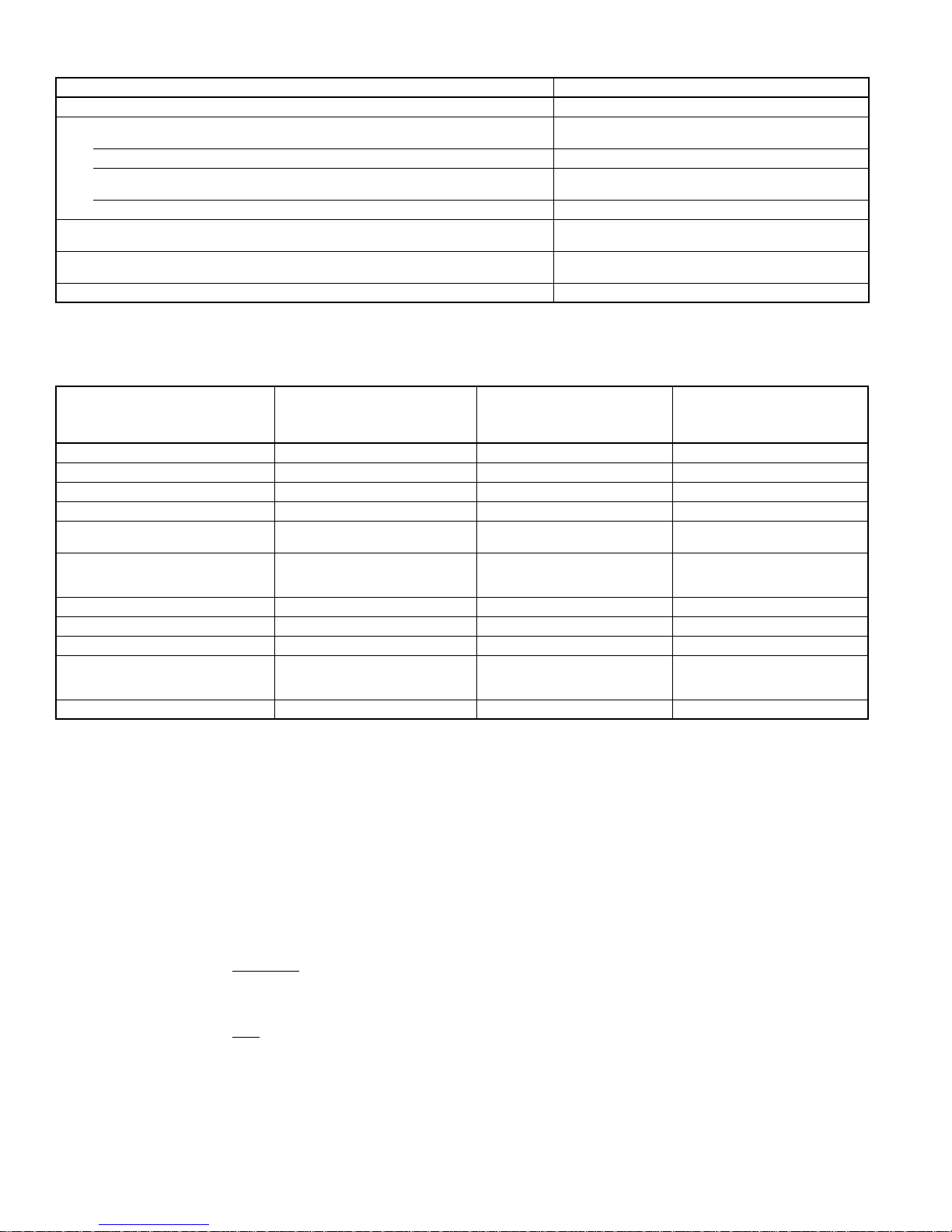
UNIT
SIZE-SERIES
024-G 71 62.0 61.5 63.0 65.0 62.0 57.5 48.0
030-F 71 60.5 59.0 62.5 65.0 63.0 59.5 52.0
036-F 73 60.0 62.0 65.0 68.0 64.0 61.0 52.5
042-F 73 60.0 63.0 67.0 68.0 66.0 62.0 54.0
048-B 76 57.5 63.5 69.0 71.0 63.0 58.0 50.5
060-A 78 56.5 67.0 71.5 70.5 70.5 60.5 53.0
NOTE: Tested in accordance with ARI Standard 270.95. (Not listed with ARI.)
STANDARD
RATING
125 250 500 1000 2000 4000 8000
A-WTD. SOUND POWER (dBA)
TYPICAL OCTAVE BAND SPECTRUM (without tone adjustment)
—9—
Page 10
UNIT
SIZE-SERIES
024-G
See notes on page 23.
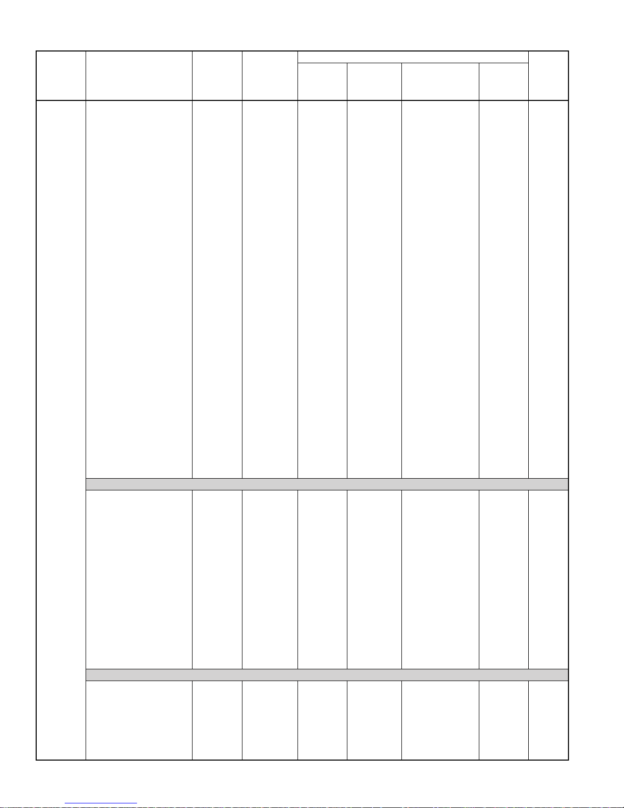
COMBINATION RATINGS
SEER
Bryant Gas
Furnace or
INDOOR
MODEL
*CK5PA036 23,600 TXV — 14.00 — — 12.15
CC5A/CD5AA024 22,800 NONE — — 13.50 — 11.65
CC5A/CD5AA030 22,800 NONE — — 13.50 — 11.80
CC5A/CD5AA036 23,600 NONE — — 14.00 — 12.05
CC5A/CD5AW024 22,800 NONE — — 13.50 — 11.65
CC5A/CD5AW030 23,000 NONE — — 13.50 — 11.80
CC5A/CD5AW036 23,600 NONE — — 14.00 — 12.05
CE3AA024 22,800 NONE — — 13.50 — 11.80
CE3AA030 23,000 NONE — — 13.50 — 11.90
CE3AA036 23,400 NONE — — 14.00 — 11.95
CF5AA024 22,800 NONE — — 13.50 — 11.65
CF5AA036 23,400 NONE — — 14.00 — 12.05
CK3BA024 22,800 NONE — — 13.50 — 11.85
CK3BA030 23,000 NONE — — 13.50 — 11.90
CK3BA036 23,600 NONE — — 14.00 — 12.15
CK5A/CK5BA024 22,800 NONE — — 13.50 — 11.85
CK5A/CK5BA030 23,000 NONE — — 13.50 — 11.90
CK5A/CK5BA036 23,600 NONE — — 14.00 — 12.15
CK5A/CK5BT036 23,600 NONE — — 14.00 — 12.15
CK5A/CK5BW024 22,800 NONE — — 13.50 — 11.85
CK5A/CK5BW030 23,000 NONE — — 13.50 — 11.90
CK5A/CK5BW036 23,600 NONE — — 14.00 — 12.15
CK5PA024 22,800 TXV — 13.50 — — 11.85
CK5PA030 23,000 TXV — 13.50 — — 11.90
CK5PT036 23,600 TXV — 14.00 — — 12.15
CK5PW024 22,800 TXV — 13.50 — — 11.85
CK5PW030 23,000 TXV — 13.50 — — 11.90
CK5PW036 23,600 TXV — 14.00 — — 12.15
F(A,B)4BN(F,C)024 23,000 TDR — — — 13.50 11.90
F(A,B)4BN(F,C)030 23,400 TDR — — — 14.00 12.10
F(A,B)4BN(F,C)036 23,400 TDR — — — 13.50 11.60
FC4CNF024 23,000 TDR&TXV 13.50 — — — 11.90
FC4CNF030 23,400 TDR&TXV 14.00 — — — 12.10
FC4CNF036 23,400 TDR&TXV 13.50 — — — 11.60
FE4ANF002 23,800 TDR&TXV 15.50 — — — 13.45
FE4ANF003 24,000 TDR&TXV 15.50 — — — 13.65
FF1DNA024 23,000 TDR — — — 13.50 11.95
FF1DNA030 23,400 TDR — — — 13.50 11.75
FF1DNE024 23,000 TDR&TXV 13.50 — — — 11.95
FF1DNE030 23,400 TDR&TXV 13.50 — — — 11.75
FG3AAA024 22,400 NONE — — 13.50 — 11.50
FG3AAA036 23,000 NONE — — 13.50 — 11.85
FK4DNF001 23,600 TDR&TXV 15.00 — — — 13.30
FK4DNF002 23,800 TDR&TXV 15.50 — — — 13.45
FK4DNF003 24,000 TDR&TXV 15.50 — — — 13.65
FV4BNF002 23,800 TDR&TXV 15.50 — — — 13.45
FV4BNF003 24,000 TDR&TXV 15.50 — — — 13.65
FX4BNF030 23,400 TDR&TXV 14.00 — — — 12.20
FX4BNF036 23,400 TDR&TXV 14.00 — — — 12.15
CC5A/CD5AA024 22,800 TDR — — — 14.50 12.65
CC5A/CD5AA030 23,000 TDR — — — 14.50 12.90
CC5A/CD5AA036 23,600 TDR — — — 15.00 13.20
CC5A/CD5AW024 22,800 TDR — — — 14.50 12.75
CC5A/CD5AW030 23,000 TDR — — — 14.50 12.90
CE3AA024 22,800 TDR — — — 14.50 12.80
CE3AA030 23,000 TDR — — — 14.50 13.00
CE3AA036 23,600 TDR — — — 15.00 13.05
CK3BA024 22,800 TDR — — — 14.50 13.05
CK3BA030 23,000 TDR — — — 14.50 13.10
CK3BA036 23,600 TDR — — — 15.00 13.25
CK5A/CK5BA024 22,800 TDR — — — 14.50 12.90
CK5A/CK5BA030 23,000 TDR — — — 14.50 13.00
CK5A/CK5BA036 23,600 TDR — — — 15.00 13.25
CK5A/CK5BT036 23,600 TDR — — — 15.00 13.25
CK5A/CK5BW024 22,800 TDR — — — 14.50 12.90
CK5A/CK5BW030 23,000 TDR — — — 14.50 13.05
CK5PA024 22,800 TDR&TXV 14.50 — — — 12.90
CK5PA030 23,000 TDR&TXV 14.50 — — — 13.00
CK5PA036 23,600 TDR&TXV 15.00 — — — 13.25
CK5PT036 23,600 TDR&TXV 15.00 — — — 13.25
CK5PW024 22,800 TDR&TXV 14.50 — — — 12.90
CK5PW030 23,000 TDR&TXV 14.50 — — — 13.05
CC5A/CD5AA024 22,800 TDR — — — 14.50 12.80
CC5A/CD5AA030 23,000 TDR — — — 14.50 13.05
CC5A/CD5AA036 23,600 TDR — — — 15.00 13.30
CC5A/CD5AW024 22,800 TDR — — — 14.50 12.90
CC5A/CD5AW030 23,000 TDR — — — 14.50 13.05
CC5A/CD5AW036 23,600 TDR — — — 15.00 13.35
CE3AA024 22,800 TDR — — — 14.50 12.90
CE3AA030 23,000 TDR — — — 14.50 13.15
CE3AA036 23,600 TDR — — — 15.00 13.20
CK3BA024 22,800 TDR — — — 14.50 13.20
Cooling
Capacity
COILS + 315(A,J)AV036070 VARIABLE-SPEED FURNACE
COILS + 315(A,J)AV048090 VARIABLE-SPEED FURNACE
Factory
Enhance
Standard
Rating
Accessory
TDR†
Bryant Gas Furnace
or Accessory TDR†
and Puron TXV‡
Accessory
Puron TXV‡
EER
—10—
Page 11

UNIT
SIZE-SERIES
024-G
See notes on page 23.
INDOOR
MODEL
CK3BA030 23,000 TDR — — — 14.50 13.25
CK3BA036 23,600 TDR — — — 15.00 13.40
CK5A/CK5BA024 22,800 TDR — — — 14.50 13.05
CK5A/CK5BA030 23,000 TDR — — — 14.50 13.15
CK5A/CK5BA036 23,600 TDR — — — 15.00 13.40
CK5A/CK5BT036 23,600 TDR — — — 15.00 13.40
CK5A/CK5BW024 22,800 TDR — — — 14.50 13.05
CK5A/CK5BW030 23,000 TDR — — — 14.50 13.20
CK5A/CK5BW036 23,600 TDR — — — 15.00 13.40
CK5PA024 22,800 TDR&TXV 14.50 — — — 13.05
CK5PA030 23,000 TDR&TXV 14.50 — — — 13.15
CK5PA036 23,600 TDR&TXV 15.00 — — — 13.40
CK5PT036 23,600 TDR&TXV 15.00 — — — 13.40
CK5PW024 22,800 TDR&TXV 14.50 — — — 13.05
CK5PW030 23,000 TDR&TXV 14.50 — — — 13.20
CK5PW036 23,600 TDR&TXV 15.00 — — — 13.40
CC5A/CD5AA036 23,600 TDR — — — 15.00 13.25
CC5A/CD5AW024 22,800 TDR — — — 14.50 12.80
CC5A/CD5AW030 23,000 TDR — — — 14.50 13.00
CC5A/CD5AW036 23,600 TDR — — — 15.00 13.30
CE3AA024 22,800 TDR — — — 14.50 12.75
CE3AA030 23,000 TDR — — — 14.50 13.05
CE3AA036 23,600 TDR — — — 15.00 13.10
CK3BA024 22,800 TDR — — — 14.50 13.15
CK3BA030 23,000 TDR — — — 14.50 13.20
CK3BA036 23,600 TDR — — — 15.00 13.30
CK5A/CK5BA036 23,600 TDR — — — 15.00 13.30
CK5A/CK5BT036 23,600 TDR — — — 15.00 13.30
CK5A/CK5BW024 22,800 TDR — — — 14.50 12.95
CK5A/CK5BW030 23,000 TDR — — — 14.50 13.10
CK5A/CK5BW036 23,600 TDR — — — 15.00 13.35
CK5PA036 23,600 TDR&TXV 15.00 — — — 13.30
CK5PT036 23,600 TDR&TXV 15.00 — — — 13.30
CK5PW024 22,800 TDR&TXV 14.50 — — — 12.95
CK5PW030 23,000 TDR&TXV 14.50 — — — 13.10
CK5PW036 23,600 TDR&TXV 15.00 — — — 13.35
CC5A/CD5AW036 23,600 TDR — — — 15.00 13.30
CE3AA024 22,800 TDR — — — 14.50 12.80
CE3AA030 23,000 TDR — — — 14.50 13.10
CE3AA036 23,600 TDR — — — 15.00 13.15
CK5A/CK5BW036 23,600 TDR — — — 15.00 13.35
CK5PW036 23,600 TDR&TXV 15.00 — — — 13.35
CC5A/CD5AW036 23,600 TDR — — — 15.00 13.35
CE3AA024 22,800 TDR — — — 14.50 12.85
CE3AA030 23,000 TDR — — — 14.50 13.10
CE3AA036 23,600 TDR — — — 15.00 13.15
CK5A/CK5BW036 23,600 TDR — — — 15.00 13.40
CK5PW036 23,600 TDR&TXV 15.00 — — — 13.40
CC5A/CD5AW036 23,600 TDR — — — 15.00 13.25
CE3AA024 22,800 TDR — — — 14.50 12.75
CE3AA030 23,000 TDR — — — 14.50 13.00
CE3AA036 23,600 TDR — — — 15.00 13.05
CK5A/CK5BW036 23,600 TDR — — — 15.00 13.30
CK5PW036 23,600 TDR&TXV 15.00 — — — 13.30
CC5A/CD5AA024 22,800 TDR — — — 14.50 12.70
CC5A/CD5AA030 23,000 TDR — — — 14.50 12.95
CC5A/CD5AA036 23,600 TDR — — — 15.00 13.25
CC5A/CD5AW024 22,800 TDR — — — 14.50 12.80
CC5A/CD5AW030 23,000 TDR — — — 14.50 12.95
CC5A/CD5AW036 23,600 TDR — — — 15.00 13.25
CE3AA024 22,800 TDR — — — 14.50 12.80
CE3AA030 23,000 TDR — — — 14.50 13.05
CE3AA036 23,600 TDR — — — 15.00 13.10
CK3BA024 22,800 TDR — — — 14.50 13.10
CK3BA030 23,000 TDR — — — 14.50 13.15
CK3BA036 23,600 TDR — — — 15.00 13.30
CK5A/CK5BA024 22,800 TDR — — — 14.50 12.95
CK5A/CK5BA030 23,000 TDR — — — 14.50 13.05
CK5A/CK5BA036 23,600 TDR — — — 15.00 13.30
CK5A/CK5BT036 23,600 TDR — — — 15.00 13.30
CK5A/CK5BW024 22,800 TDR — — — 14.50 12.95
CK5A/CK5BW030 23,000 TDR — — — 14.50 13.10
CK5A/CK5BW036 23,600 TDR — — — 15.00 13.35
CK5PA024 22,800 TDR&TXV 14.50 — — — 12.95
CK5PA030 23,000 TDR&TXV 14.50 — — — 13.05
CK5PA036 23,600 TDR&TXV 15.00 — — — 13.30
CK5PT036 23,600 TDR&TXV 15.00 — — — 13.30
COMBINATION RATINGS continued
Bryant Gas
Furnace or
Cooling
Capacity
COILS + 315(A,J)AV060110 VARIABLE-SPEED FURNACE
COILS + 315(A,J)AV066135 VARIABLE-SPEED FURNACE
COILS + 315(A,J)AV066155 VARIABLE-SPEED FURNACE
Factory
Enhance
COILS + 355MAV042040 VARIABLE-SPEED FURNACE
COILS + 355MAV042060 VARIABLE-SPEED FURNACE
Standard
Rating
—11—
Accessory
TDR†
SEER
Bryant Gas Furnace
or Accessory TDR†
and Puron TXV‡
Accessory
Puron TXV‡
EER
Page 12
UNIT
SIZE-SERIES
024-G
030-F
See notes on page 23.
COMBINATION RATINGS continued
SEER
Bryant Gas
Furnace or
INDOOR
MODEL
CK5PW024 22,800 TDR&TXV 14.50 — — — 12.95
CK5PW030 23,000 TDR&TXV 14.50 — — — 13.10
CK5PW036 23,600 TDR&TXV 15.00 — — — 13.35
CC5A/CD5AA036 23,600 TDR — — — 15.00 13.20
CC5A/CD5AW024 22,800 TDR — — — 14.50 12.75
CC5A/CD5AW030 23,000 TDR — — — 14.50 12.95
CC5A/CD5AW036 23,600 TDR — — — 15.00 13.25
CE3AA024 22,800 TDR — — — 14.50 12.75
CE3AA030 23,000 TDR — — — 14.50 13.00
CE3AA036 23,600 TDR — — — 15.00 13.10
CK3BA024 22,800 TDR — — — 14.50 13.10
CK3BA030 23,000 TDR — — — 14.50 13.15
CK3BA036 23,600 TDR — — — 15.00 13.25
CK5A/CK5BA036 23,600 TDR — — — 15.00 13.25
CK5A/CK5BT036 23,600 TDR — — — 15.00 13.25
CK5A/CK5BW024 22,800 TDR — — — 14.50 12.95
CK5A/CK5BW030 23,000 TDR — — — 14.50 13.05
CK5A/CK5BW036 23,600 TDR — — — 15.00 13.30
CK5PA036 23,600 TDR&TXV 15.00 — — — 13.25
CK5PT036 23,600 TDR&TXV 15.00 — — — 13.25
CK5PW024 22,800 TDR&TXV 14.50 — — — 12.90
CK5PW030 23,000 TDR&TXV 14.50 — — — 13.05
CK5PW036 23,600 TDR&TXV 15.00 — — — 13.30
CC5A/CD5AA036 23,600 TDR — — — 15.00 13.20
CC5A/CD5AW024 22,800 TDR — — — 14.50 12.80
CC5A/CD5AW030 23,000 TDR — — — 14.50 12.95
CC5A/CD5AW036 23,600 TDR — — — 15.00 13.25
CE3AA024 22,800 TDR — — — 14.50 12.80
CE3AA030 23,000 TDR — — — 14.50 13.05
CE3AA036 23,600 TDR — — — 15.00 13.10
CK3BA024 22,800 TDR — — — 14.50 13.10
CK3BA030 23,000 TDR — — — 14.50 13.15
CK3BA036 23,600 TDR — — — 15.00 13.30
CK5A/CK5BA036 23,600 TDR — — — 15.00 13.30
CK5A/CK5BT036 23,600 TDR — — — 15.00 13.30
CK5A/CK5BW024 22,800 TDR — — — 14.50 12.95
CK5A/CK5BW030 23,000 TDR — — — 14.50 13.10
CK5A/CK5BW036 23,600 TDR — — — 15.00 13.30
CK5PA036 23,600 TDR&TXV 15.00 — — — 13.30
CK5PT036 23,600 TDR&TXV 15.00 — — — 13.30
CK5PW024 22,800 TDR&TXV 14.50 — — — 12.95
CK5PW030 23,000 TDR&TXV 14.50 — — — 13.10
CK5PW036 23,600 TDR&TXV 15.00 — — — 13.30
CC5A/CD5AA036 23,600 TDR — — — 15.00 13.25
CC5A/CD5AW024 22,800 TDR — — — 14.50 12.80
CC5A/CD5AW030 23,000 TDR — — — 14.50 13.00
CC5A/CD5AW036 23,600 TDR — — — 15.00 13.30
CE3AA024 22,800 TDR — — — 14.50 12.80
CE3AA030 23,000 TDR — — — 14.50 13.05
CE3AA036 23,600 TDR — — — 15.00 13.15
CK3BA024 22,800 TDR — — — 14.50 13.15
CK3BA030 23,000 TDR — — — 14.50 13.20
CK3BA036 23,600 TDR — — — 15.00 13.30
CK5A/CK5BA036 23,600 TDR — — — 15.00 13.30
CK5A/CK5BT036 23,600 TDR — — — 15.00 13.30
CK5A/CK5BW024 22,800 TDR — — — 14.50 12.95
CK5A/CK5BW030 23,000 TDR — — — 14.50 13.10
CK5A/CK5BW036 23,600 TDR — — — 15.00 13.35
CK5PA036 23,600 TDR&TXV 15.00 — — — 13.30
CK5PT036 23,600 TDR&TXV 15.00 — — — 13.30
CK5PW024 22,800 TDR&TXV 14.50 — — — 12.95
CK5PW030 23,000 TDR&TXV 14.50 — — — 13.10
CK5PW036 23,600 TDR&TXV 15.00 — — — 13.35
CC5A/CD5AW036 23,600 TDR — — — 15.00 13.20
CE3AA024 22,800 TDR — — — 14.50 12.75
CE3AA030 23,000 TDR — — — 14.50 13.00
CE3AA036 23,600 TDR — — — 15.00 13.05
CK5A/CK5BW036 23,600 TDR — — — 15.00 13.30
CK5PW036 23,600 TDR&TXV 15.00 — — — 13.30
*CK5PA042 30,000 TXV — 14.00 — — 12.10
CC5A/CD5AA030 29,000 NONE — — 13.50 — 11.70
CC5A/CD5AA036 29,600 NONE — — 13.80 — 12.05
CC5A/CD5AA042 30,000 NONE — — 13.70 — 12.05
CC5A/CD5AW030 29,000 NONE — — 13.50 — 11.70
CC5A/CD5AW036 29,600 NONE — — 13.80 — 12.05
CC5A/CD5AW042 30,000 NONE — — 13.70 — 12.00
CE3AA030 29,000 NONE — — 13.50 — 11.85
Cooling
Capacity
Factory
Enhance
COILS + 355MAV042080 VARIABLE-SPEED FURNACE
COILS + 355MAV060080 VARIABLE-SPEED FURNACE
COILS + 355MAV060100 VARIABLE-SPEED FURNACE
COILS + 355MAV060120 VARIABLE-SPEED FURNACE
Standard
Rating
Accessory
TDR†
Bryant Gas Furnace
or Accessory TDR†
and Puron TXV‡
Accessory
Puron TXV‡
EER
—12—
Page 13
UNIT
SIZE-SERIES
030-F
See notes on page 23.
INDOOR
MODEL
CE3AA036 29,600 NONE — — 13.50 — 11.95
CE3AA042 30,000 NONE — — 14.00 — 12.10
CF5AA036 29,600 NONE — — 13.50 — 12.00
CK3BA030 29,000 NONE — — 13.50 — 11.75
CK3BA036 29,600 NONE — — 13.80 — 12.10
CK3BA042 30,000 NONE — — 14.00 — 12.10
CK5A/CK5BA030 29,000 NONE — — 13.50 — 11.75
CK5A/CK5BA036 29,600 NONE — — 13.80 — 12.10
CK5A/CK5BA042 30,000 NONE — — 14.00 — 12.10
CK5A/CK5BT036 29,600 NONE — — 13.80 — 12.10
CK5A/CK5BT042 30,000 NONE — — 14.00 — 12.10
CK5A/CK5BW030 29,000 NONE — — 13.50 — 11.75
CK5A/CK5BW036 29,600 NONE — — 13.80 — 12.10
CK5PA030 29,000 TXV — 13.50 — — 11.75
CK5PA036 29,600 TXV — 13.80 — — 12.10
CK5PT036 29,600 TXV — 13.80 — — 12.10
CK5PT042 30,000 TXV — 14.00 — — 12.10
CK5PW030 29,000 TXV — 13.50 — — 11.75
CK5PW036 29,600 TXV — 13.80 — — 12.10
F(A,B)4AN(F,B,C)042 30,000 TDR — — — 13.50 11.70
F(A,B)4AN(F,C)030 29,000 TDR — — — 14.00 12.00
F(A,B)4AN(F,C)036 29,600 TDR — — — 13.50 11.75
F(A,B)4BN(F,B,C)042 30,000 TDR — — — 13.50 11.70
F(A,B)4BN(F,C)030 29,000 TDR — — — 14.00 12.00
F(A,B)4BN(F,C)036 29,600 TDR — — — 13.50 11.75
FC4BN(F,B)042 30,000 TDR&TXV 13.50 — — — 11.70
FC4BNF030 29,000 TDR&TXV 14.00 — — — 12.00
FC4BNF036 29,600 TDR&TXV 13.50 — — — 11.75
FC4CN(F,B)042 30,000 TDR&TXV 13.50 — — — 11.70
FC4CNF030 29,000 TDR&TXV 14.00 — — — 12.00
FC4CNF036 29,600 TDR&TXV 13.50 — — — 11.75
FE4ANF002 29,600 TDR&TXV — — — — 13.15
FE4ANF003 29,800 TDR&TXV — — — — 13.60
FE4ANF005 30,000 TDR&TXV — — — — 14.00
FF1DNA030 29,000 TDR — — — 13.50 11.90
FG3AAA036 29,600 NONE — — 13.50 — 11.85
FK4CNF001 29,000 TDR&TXV 15.00 — — — 13.05
FK4CNF002 29,600 TDR&TXV 15.00 — — — 13.15
FK4CNF003 29,800 TDR&TXV 15.50 — — — 12.60
FK4CNF005 30,000 TDR&TXV 15.75 — — — 14.00
FK4DNF001 29,000 TDR&TXV 15.00 — — — 13.05
FK4DNF002 29,600 TDR&TXV 15.00 — — — 13.15
FK4DNF003 29,800 TDR&TXV 15.50 — — — 12.60
FK4DNF005 30,000 TDR&TXV 15.75 — — — 14.00
FV4ANF002 29,600 TDR&TXV 15.20 — — — 13.15
FV4ANF003 29,800 TDR&TXV 15.60 — — — 13.60
FV4ANF005 30,000 TDR&TXV 15.75 — — — 14.00
FV4BNF002 29,600 TDR&TXV 15.20 — — — 13.15
FV4BNF003 29,800 TDR&TXV 15.60 — — — 13.60
FV4BNF005 30,000 TDR&TXV 15.75 — — — 14.00
FX4ANF030 29,000 TDR&TXV 14.00 — — — 12.15
FX4ANF036 29,600 TDR&TXV 13.85 — — — 11.90
FX4ANF042 30,000 TDR&TXV 13.60 — — — 11.90
FX4BNF030 29,000 TDR&TXV 14.00 — — — 12.15
FX4BNF036 29,600 TDR&TXV 13.85 — — — 11.90
FX4BNF042 30,000 TDR&TXV 13.60 — — — 11.90
CC5A/CD5AA030 29,000 TDR — — — 14.50 12.65
CC5A/CD5AA036 29,600 TDR — — — 15.00 13.05
CC5A/CD5AW030 29,000 TDR — — — 14.50 12.65
CE3AA030 29,000 TDR — — — 14.50 12.75
CE3AA036 29,600 TDR — — — 15.00 12.85
CK3BA030 29,000 TDR — — — 14.50 12.70
CK3BA036 29,600 TDR — — — 15.00 13.10
CK5A/CK5BA030 29,000 TDR — — — 14.50 12.70
CK5A/CK5BA036 29,600 TDR — — — 15.00 13.10
CK5A/CK5BT036 29,600 TDR — — — 15.00 13.10
CK5A/CK5BW030 29,000 TDR — — — 14.50 12.70
CK5PA030 29,000 TDR&TXV 14.50 — — — 12.70
CK5PA036 29,600 TDR&TXV 15.00 — — — 13.10
CK5PT036 29,600 TDR&TXV 15.00 — — — 13.10
CK5PW030 29,000 TDR&TXV 14.50 — — — 12.70
CC5A/CD5AA030 29,000 TDR — — — 14.50 12.80
CC5A/CD5AA036 29,600 TDR — — — 15.00 13.25
CC5A/CD5AA042 30,000 TDR — — — 15.00 13.30
CC5A/CD5AW030 29,000 TDR — — — 14.50 12.80
CC5A/CD5AW036 29,600 TDR — — — 15.00 13.25
CE3AA030 29,000 TDR — — — 14.50 12.95
CE3AA036 29,600 TDR — — — 15.00 13.15
CE3AA042 30,000 TDR — — — 15.00 13.30
CK3BA030 29,000 TDR — — — 14.50 12.85
CK3BA036 29,600 TDR — — — 15.00 13.30
CK3BA042 30,000 TDR — — — 15.00 13.30
COMBINATION RATINGS continued
Bryant Gas
Furnace or
Cooling
Capacity
COILS + 315(A,J)AV036070 VARIABLE-SPEED FURNACE
COILS + 315(A,J)AV048090 VARIABLE-SPEED FURNACE
Factory
Enhance
Standard
Rating
—13—
Accessory
TDR†
SEER
Bryant Gas Furnace
or Accessory TDR†
and Puron TXV‡
Accessory
Puron TXV‡
EER
Page 14
COMBINATION RATINGS continued
UNIT
SIZE-SERIES
030-F
See notes on page 23.
INDOOR
MODEL
CK5A/CK5BA030 29,000 TDR — — — 14.50 12.85
CK5A/CK5BA036 29,600 TDR — — — 15.00 13.30
CK5A/CK5BA042 30,000 TDR — — — 15.00 13.30
CK5A/CK5BT042 30,000 TDR — — — 15.00 13.30
CK5A/CK5BW030 29,000 TDR — — — 14.50 12.85
CK5A/CK5BW036 29,600 TDR — — — 15.00 13.30
CK5PA030 29,000 TDR&TXV 15.00 — — — 12.85
CK5PA036 29,600 TDR&TXV 15.00 — — — 13.30
CK5PA042 30,000 TDR&TXV 15.00 — — — 13.30
CK5PT036 29,600 TDR&TXV 15.00 — — — 13.30
CK5PT042 30,000 TDR&TXV 15.00 — — — 13.30
CK5PW030 29,000 TDR&TXV 15.00 — — — 12.85
CK5PW036 29,600 TDR&TXV 15.00 — — — 13.30
CC5A/CD5AA036 29,600 TDR — — — 15.00 13.45
CC5A/CD5AA042 30,000 TDR — — — 15.00 13.50
CC5A/CD5AW030 29,000 TDR — — — 14.50 13.05
CC5A/CD5AW036 29,600 TDR — — — 15.00 13.50
CC5A/CD5AW042 30,000 TDR — — — 15.00 13.40
CE3AA030 29,000 TDR — — — 14.50 13.10
CE3AA036 29,600 TDR — — — 15.00 13.30
CE3AA042 30,000 TDR — — — 15.00 13.55
CK3BA030 29,000 TDR — — — 14.50 13.25
CK3BA036 29,600 TDR — — — 15.00 13.50
CK3BA042 30,000 TDR — — — 15.00 13.55
CK5A/CK5BA036 29,600 TDR — — — 15.00 13.50
CK5A/CK5BA042 30,000 TDR — — — 15.00 13.55
CK5A/CK5BE042 30,000 TDR — — — 15.00 13.20
CK5A/CK5BT036 29,600 TDR — — — 15.00 13.50
CK5A/CK5BT042 30,000 TDR — — — 15.00 13.55
CK5A/CK5BW030 29,000 TDR — — — 14.50 13.15
CK5A/CK5BW036 29,600 TDR — — — 15.00 13.55
CK5PA036 29,600 TDR&TXV 15.00 — — — 13.50
CK5PA042 30,000 TDR&TXV 15.00 — — — 13.55
CK5PE042 30,000 TDR&TXV 15.00 — — — 13.60
CK5PT036 29,600 TDR&TXV 15.00 — — — 13.50
CK5PT042 30,000 TDR&TXV 15.00 — — — 13.55
CK5PW030 29,000 TDR&TXV 14.50 — — — 13.15
CK5PW036 29,600 TDR&TXV 15.00 — — — 13.55
CC5A/CD5AW036 29,600 TDR — — — 15.00 13.65
CE3AA030 29,000 TDR — — — 15.00 13.25
CE3AA036 29,600 TDR — — — 15.00 13.45
CK5A/CK5BW036 29,600 TDR — — — 15.00 13.70
CK5PW036 29,600 TDR&TXV 15.00 — — — 13.70
CC5A/CD5AW036 29,600 TDR — — — 15.00 13.70
CE3AA030 29,000 TDR — — — 14.00 15.45
CE3AA036 29,600 TDR — — — 15.00 13.50
CK5A/CK5BW036 29,600 TDR — — — 15.00 13.75
CK5PW036 29,600 TDR&TXV 14.50 — — — 16.00
CC5A/CD5AA042 30,000 TDR — — — 15.00 13.00
CC5A/CD5AW030 29,000 TDR — — — 14.00 12.30
CC5A/CD5AW036 29,600 TDR — — — 15.00 12.90
CK5A/CK5BA042 30,000 TDR — — — 15.00 13.05
CK5A/CK5BW030 29,000 TDR — — — 14.00 12.35
CK5A/CK5BW036 29,600 TDR — — — 15.00 12.90
CK5PA042 30,000 TDR&TXV 15.00 — — — 13.05
CK5PW030 29,000 TDR&TXV 14.00 — — — 12.35
CK5PW036 29,600 TDR&TXV 15.00 — — — 12.90
CC5A/CD5AA036 29,600 TDR — — — 14.70 12.85
CC5A/CD5AW030 29,000 TDR — — — 14.00 12.30
CK3BA030 29,000 TDR — — — 14.50 12.40
CK3BA036 29,600 TDR — — — 15.00 12.90
CK3BA042 30,000 TDR — — — 15.00 13.00
CK5A/CK5BA036 29,600 TDR — — — 14.70 12.90
CK5A/CK5BW030 29,000 TDR — — — 14.00 12.40
CK5PA036 29,600 TDR&TXV 14.70 — — — 12.90
CK5PW030 29,000 TDR&TXV 14.00 — — — 12.40
CC5A/CD5AA042 30,000 TDR — — — 15.00 13.10
CC5A/CD5AW030 29,000 TDR — — — 14.50 12.40
CC5A/CD5AW036 29,600 TDR — — — 15.00 13.00
CK5A/CK5BA042 30,000 TDR — — — 15.00 13.15
CK5A/CK5BW030 29,000 TDR — — — 14.50 12.50
CK5A/CK5BW036 29,600 TDR — — — 15.00 13.05
CK5PA042 30,000 TDR&TXV 15.00 — — — 13.15
CK5PW030 29,000 TDR&TXV 14.50 — — — 12.50
CK5PW036 29,600 TDR&TXV 15.00 — — — 13.05
Cooling
Capacity
SEER
Bryant Gas
Furnace or
Factory
Enhance
COILS + 315(A,J)AV060110 VARIABLE-SPEED FURNACE
COILS + 315(A,J)AV066135 VARIABLE-SPEED FURNACE
COILS + 315(A,J)AV066155 VARIABLE-SPEED FURNACE
COILS + 355MAV042040 VARIABLE-SPEED FURNACE
COILS + 355MAV042060 VARIABLE-SPEED FURNACE
COILS + 355MAV042080 VARIABLE-SPEED FURNACE
Standard
Rating
Accessory
TDR†
Bryant Gas Furnace
or Accessory TDR†
and Puron TXV‡
—14—
Accessory
Puron TXV‡
EER
Page 15

UNIT
SIZE-SERIES
030-F
036-F
F(A,B)4(A,B)N(F,B,C)042 35,600 TDR — — — 13.70 11.90
F(A,B)4(A,B)N(F,B,C)048 36,000 TDR — — — 13.80 11.95
F(A,B)4(A,B)N(F,C)036 35,000 TDR — — — 13.20 11.60
See notes on page 23.
COMBINATION RATINGS continued
SEER
Bryant Gas
Furnace or
INDOOR
MODEL
CC5A/CD5AA042 30,000 TDR — — — 15.00 12.95
CC5A/CD5AW030 29,000 TDR — — — 14.30 12.25
CC5A/CD5AW036 29,600 TDR — — — 14.70 12.85
CK3BA042 30,000 TDR — — — 15.00 13.00
CK5A/CK5BA042 30,000 TDR — — — 15.00 13.00
CK5A/CK5BW030 29,000 TDR — — — 14.30 12.30
CK5A/CK5BW036 29,600 TDR — — — 14.70 12.85
CK5PA042 30,000 TDR&TXV 15.00 — — — 13.00
CK5PW030 29,000 TDR&TXV 14.30 — — — 12.30
CK5PW036 29,600 TDR&TXV 14.70 — — — 12.85
CC5A/CD5AA042 30,000 TDR — — — 15.00 13.35
CC5A/CD5AW030 29,000 TDR — — — 14.70 12.75
CC5A/CD5AW036 29,600 TDR — — — 15.00 13.30
CK3BA042 30,000 TDR — — — 15.00 13.40
CK5A/CK5BA042 30,000 TDR — — — 15.00 13.40
CK5A/CK5BW030 29,000 TDR — — — 14.70 12.80
CK5A/CK5BW036 29,600 TDR — — — 15.00 13.30
CK5PA042 30,000 TDR&TXV 15.00 — — — 13.40
CK5PW030 29,000 TDR&TXV 14.70 — — — 12.80
CK5PW036 29,600 TDR&TXV 15.00 — — — 13.30
CC5A/CD5AA042 30,000 TDR — — — 15.00 13.30
CC5A/CD5AW036 29,600 TDR — — — 15.00 13.20
CK5A/CK5BA042 30,000 TDR — — — 15.00 13.35
CK5A/CK5BW036 29,600 TDR — — — 15.00 13.25
CK5PA042 30,000 TDR&TXV 15.00 — — — 13.35
CK5PW036 29,600 TDR&TXV 15.00 — — — 13.25
*CK5PA048 36,000 TXV — 14.00 — — 12.05
CC5A/CD5AA036 35,000 NONE — — 13.70 — 11.95
CC5A/CD5AA042 35,600 NONE — — 13.70 — 11.95
CC5A/CD5AC048 35,600 NONE — — 13.70 — 11.80
CC5A/CD5AW036 35,000 NONE — — 13.70 — 11.95
CC5A/CD5AW042 35,600 NONE — — 13.70 — 11.85
CC5A/CD5AW048 36,000 NONE — — 13.70 — 12.00
CD5AA048 36,000 NONE — — 13.70 — 12.00
CE3AA036 35,000 NONE — — 13.50 — 11.80
CE3AA042 35,600 NONE — — 14.00 — 12.05
CE3AA048 36,000 NONE — — 14.00 — 12.10
CF5AA036 35,000 NONE — — 13.50 — 11.90
CF5AA048 36,000 NONE — — 13.80 — 12.00
CK3BA036 35,000 NONE — — 13.70 — 11.95
CK3BA042 35,600 NONE — — 13.70 — 11.95
CK3BA048 36,000 NONE — — 14.00 — 12.05
CK5A/CK5BA036 35,000 NONE — — 13.70 — 11.95
CK5A/CK5BA042 35,600 NONE — — 13.70 — 11.95
CK5A/CK5BA048 36,000 NONE — — 14.00 — 12.05
CK5A/CK5BE042 36,000 NONE — — 14.00 — 12.05
CK5A/CK5BT036 35,000 NONE — — 13.70 — 11.95
CK5A/CK5BT042 35,600 NONE — — 13.70 — 11.95
CK5A/CK5BT048 36,000 NONE — — 14.00 — 12.05
CK5A/CK5BW036 35,000 NONE — — 13.70 — 11.95
CK5A/CK5BW048 36,000 NONE — — 14.00 — 12.05
CK5PA036 35,000 TXV — 13.70 — — 11.95
CK5PA042 35,600 TXV — 13.70 — — 11.95
CK5PT036 35,000 TXV — 13.70 — — 11.95
CK5PT042 35,600 TXV — 13.70 — — 11.95
CK5PT048 36,000 TXV — 14.00 — — 12.05
CK5PW036 35,000 TXV — 13.70 — — 11.95
CK5PW048 36,000 TXV — 14.00 — — 12.05
FC4(B,C)N(F,B)042 35,600 TDR&TXV 13.70 — — — 11.90
FC4(B,C)N(F,B)048 36,000 TDR&TXV 13.80 — — — 11.95
FC4(B,C)NB054 36,000 TDR&TXV 14.50 — — — 12.75
FC4(B,C)NF036 35,000 TDR&TXV 13.20 — — — 11.60
FE4ANB006 36,200 TDR&TXV 15.75 — — — 14.05
FE4ANF002 35,600 TDR&TXV 14.50 — — — 12.60
FE4ANF003 35,800 TDR&TXV 15.20 — — — 13.20
FE4ANF005 36,000 TDR&TXV 15.50 — — — 13.70
FG3AAA036 35,000 NONE — — 13.50 — 11.70
FG3AAA048 36,000 NONE — — 13.80 — 12.00
FK4(C,D)NB006 36,200 TDR&TXV 15.75 — — — 14.10
FK4(C,D)NF001 35,000 TDR&TXV 14.50 — — — 12.50
FK4(C,D)NF002 35,600 TDR&TXV 14.50 — — — 12.60
FK4(C,D)NF003 35,800 TDR&TXV 15.00 — — — 13.20
FK4(C,D)NF005 36,000 TDR&TXV 15.50 — — — 13.70
FV4(A,B)NB006 36,200 TDR&TXV 15.75 — — — 14.05
FV4(A,B)NF002 35,600 TDR&TXV 14.50 — — — 12.60
FV4(A,B)NF003 35,800 TDR&TXV 15.20 — — — 13.20
Cooling
Capacity
Factory
Enhance
COILS + 355MAV060080 VARIABLE-SPEED FURNACE
COILS + 355MAV060100 VARIABLE-SPEED FURNACE
COILS + 355MAV060120 VARIABLE-SPEED FURNACE
Standard
Rating
Accessory
TDR†
Bryant Gas Furnace
or Accessory TDR†
and Puron TXV‡
Accessory
Puron TXV‡
EER
—15—
Page 16

UNIT
SIZE-SERIES
036-F
See notes on page 23.
COMBINATION RATINGS continued
SEER
Bryant Gas
Furnace or
INDOOR
MODEL
FV4(A,B)NF005 36,000 TDR&TXV 15.50 — — — 13.70
FX4(A,B)NF036 35,000 TDR&TXV 13.50 — — — 11.70
FX4(A,B)NF042 35,600 TDR&TXV 14.00 — — — 12.10
FX4(A,B)NF048 36,000 TDR&TXV 14.00 — — — 12.15
CC5A/CD5AA036 35,000 TDR — — — 14.50 12.65
CE3AA036 35,000 TDR — — — 14.50 12.55
CE3AA042 35,600 TDR — — — 15.00 12.80
CK3BA036 35,000 TDR — — — 14.50 12.70
CK5A/CK5BA036 35,000 TDR — — — 14.50 12.70
CK5A/CK5BE042 35,600 TDR — — — 15.00 12.85
CK5A/CK5BT036 35,000 TDR — — — 14.50 12.70
CK5PA036 35,000 TDR&TXV 14.50 — — — 12.70
CK5PE042 35,600 TDR&TXV 15.00 — — — 12.85
CK5PT036 35,000 TDR&TXV 14.50 — — — 12.70
CC5A/CD5AA036 35,000 TDR — — — 14.50 12.85
CC5A/CD5AA042 35,600 TDR — — — 15.00 13.05
CC5A/CD5AC048 36,000 TDR — — — 15.00 13.00
CC5A/CD5AW036 35,000 TDR — — — 14.50 12.85
CD5AA048 36,000 TDR — — — 15.00 12.80
CE3AA036 35,000 TDR — — — 14.50 12.75
CE3AA042 35,600 TDR — — — 15.00 13.00
CE3AA048 36,000 TDR — — — 15.00 13.05
CK3BA036 35,000 TDR — — — 14.50 12.95
CK3BA042 35,600 TDR — — — 15.00 13.00
CK3BA048 36,000 TDR — — — 15.00 13.15
CK5A/CK5BA036 35,000 TDR — — — 14.50 12.95
CK5A/CK5BA042 35,600 TDR — — — 15.00 13.00
CK5A/CK5BA048 36,000 TDR — — — 15.00 13.15
CK5A/CK5BE042 35,800 TDR — — — 15.00 13.10
CK5A/CK5BT036 35,000 TDR — — — 14.50 12.95
CK5A/CK5BT042 35,600 TDR — — — 15.00 13.00
CK5A/CK5BT048 36,000 TDR — — — 15.00 13.15
CK5A/CK5BW036 35,000 TDR — — — 14.50 12.95
CK5PA036 35,000 TDR&TXV 14.50 — — — 12.95
CK5PA042 35,600 TDR&TXV 15.00 — — — 13.00
CK5PA048 36,000 TDR&TXV 15.00 — — — 13.15
CK5PE042 35,600 TDR&TXV 15.00 — — — 13.10
CK5PT036 35,000 TDR&TXV 14.50 — — — 12.95
CK5PT042 35,600 TDR&TXV 15.00 — — — 13.00
CK5PT048 36,000 TDR&TXV 15.00 — — — 13.15
CK5PW036 35,000 TDR&TXV 14.50 — — — 12.95
CC5A/CD5AA036 35,000 TDR — — — 14.50 12.60
CC5A/CD5AA042 35,600 TDR — — — 15.00 12.95
CC5A/CD5AC048 36,000 TDR — — — 15.00 12.85
CC5A/CD5AW036 35,000 TDR — — — 14.50 12.90
CC5A/CD5AW042 35,600 TDR — — — 15.00 12.85
CC5A/CD5AW048 36,000 TDR — — — 15.00 13.05
CD5AA048 36,000 TDR — — — 15.00 13.05
CE3AA036 35,000 TDR — — — 14.50 12.70
CE3AA042 35,600 TDR — — — 15.00 13.00
CK3BA036 35,000 TDR — — — 14.50 12.90
CK3BA042 35,600 TDR — — — 15.00 12.95
CK3BA048 36,000 TDR — — — 15.00 13.15
CK5A/CK5BA036 35,000 TDR — — — 14.50 12.90
CK5A/CK5BA042 35,600 TDR — — — 15.00 12.95
CK5A/CK5BA048 36,000 TDR — — — 15.00 13.10
CK5A/CK5BE042 35,600 TDR — — — 15.00 13.05
CK5A/CK5BT036 35,000 TDR — — — 14.50 12.90
CK5A/CK5BT042 35,600 TDR — — — 15.00 12.95
CK5A/CK5BT048 36,000 TDR — — — 15.00 13.10
CK5A/CK5BW036 35,000 TDR — — — 14.50 12.95
CK5PA036 35,000 TDR&TXV 14.50 — — — 12.90
CK5PA042 35,600 TDR&TXV 15.00 — — — 12.95
CK5PA048 36,000 TDR&TXV 15.00 — — — 13.10
CK5PE042 35,600 TDR&TXV 15.00 — — — 13.05
CK5PT036 35,000 TDR&TXV 14.50 — — — 12.90
CK5PT042 35,600 TDR&TXV 15.00 — — — 12.95
CK5PT048 36,000 TDR&TXV 15.00 — — — 13.10
CK5PW036 35,000 TDR&TXV 14.50 — — — 12.95
CK5PW048 36,000 TDR&TXV 15.00 — — — 13.20
CC5A/CD5AA042 35,600 TDR — — — 15.00 13.10
CC5A/CD5AC048 36,000 TDR — — — 15.00 13.05
CC5A/CD5AW036 35,000 TDR — — — 14.50 12.90
CC5A/CD5AW042 35,600 TDR — — — 15.00 13.00
CC5A/CD5AW048 36,000 TDR — — — 15.00 13.20
CD5AA048 36,000 TDR — — — 15.00 13.20
CE3AA036 35,000 TDR — — — 14.50 12.80
CE3AA042 35,600 TDR — — — 15.50 13.10
Cooling
Capacity
COILS + 315(A,J)AV036070 VARIABLE-SPEED FURNACE
COILS + 315(A,J)AV048090 VARIABLE-SPEED FURNACE
COILS + 315(A,J)AV060110 VARIABLE-SPEED FURNACE
COILS + 315(A,J)AV066135 VARIABLE-SPEED FURNACE
Factory
Enhance
Standard
Rating
Accessory
TDR†
Bryant Gas Furnace
or Accessory TDR†
and Puron TXV‡
Accessory
Puron TXV‡
EER
—16—
Page 17

UNIT
SIZE-SERIES
036-F
See notes on page 23.
INDOOR
MODEL
CE3AA048 36,000 TDR — — — 15.00 13.15
CK3BA042 35,600 TDR — — — 15.00 13.05
CK3BA048 36,000 TDR — — — 15.00 13.25
CK5A/CK5BA042 35,600 TDR — — — 15.00 13.05
CK5A/CK5BA048 36,000 TDR — — — 15.00 13.25
CK5A/CK5BT042 35,600 TDR — — — 15.00 13.05
CK5A/CK5BT048 36,000 TDR — — — 15.00 13.25
CK5A/CK5BW036 35,000 TDR — — — 14.50 12.95
CK5A/CK5BW048 36,000 TDR — — — 15.00 13.25
CK5PA042 35,600 TDR&TXV 15.00 — — — 13.05
CK5PA048 36,000 TDR&TXV 15.00 — — — 13.25
CK5PT042 35,600 TDR&TXV 15.00 — — — 13.05
CK5PT048 36,000 TDR&TXV 15.00 — — — 13.25
CK5PW036 35,000 TDR&TXV 14.50 — — — 12.95
CK5PW048 36,000 TDR&TXV 15.00 — — — 13.25
CC5A/CD5AA042 35,600 TDR — — — 15.00 13.20
CC5A/CD5AC048 36,000 TDR — — — 15.00 13.10
CC5A/CD5AW036 35,000 TDR — — — 14.50 13.15
CC5A/CD5AW042 35,600 TDR — — — 15.00 13.10
CC5A/CD5AW048 36,000 TDR — — — 15.00 13.30
CD5AA048 36,000 TDR — — — 15.00 13.30
CE3AA036 35,000 TDR — — — 14.50 12.90
CE3AA042 35,600 TDR — — — 15.00 13.25
CE3AA048 36,000 TDR — — — 15.00 13.30
CK3BA042 35,600 TDR — — — 14.50 15.40
CK3BA048 36,000 TDR — — — 15.00 13.40
CK5A/CK5BA042 35,600 TDR — — — 15.00 13.25
CK5A/CK5BA048 36,000 TDR — — — 15.00 13.40
CK5A/CK5BT042 35,600 TDR — — — 15.00 13.20
CK5A/CK5BT048 36,000 TDR — — — 15.00 13.40
CK5A/CK5BW036 35,000 TDR — — — 14.50 13.20
CK5A/CK5BW048 36,000 TDR — — — 15.00 13.45
CK5PA042 35,600 TDR&TXV 14.50 — — — 15.40
CK5PA048 36,000 TDR&TXV 15.00 — — — 13.40
CK5PT042 35,600 TDR&TXV 15.00 — — — 13.20
CK5PT048 36,000 TDR&TXV 15.00 — — — 13.40
CK5PW036 35,000 TDR&TXV 14.50 — — — 13.20
CK5PW048 36,000 TDR&TXV 15.00 — — — 13.45
CC5A/CD5AA042 35,600 TDR — — — 14.50 12.75
CC5A/CD5AW036 35,000 TDR — — — 14.50 12.65
CC5A/CD5AW048 36,000 TDR — — — 14.50 12.75
CK5A/CK5BA042 35,600 TDR — — — 14.50 12.80
CK5A/CK5BW036 35,000 TDR — — — 14.50 12.70
CK5A/CK5BW048 36,000 TDR — — — 15.00 12.90
CK5PA042 35,600 TDR&TXV 14.50 — — — 12.80
CK5PW036 35,000 TDR&TXV 14.50 — — — 12.70
CK5PW048 36,000 TDR&TXV 15.00 — — — 12.90
CC5A/CD5AA036 35,000 TDR — — — 14.50 12.60
CK3BA036 35,000 TDR — — — 14.50 12.65
CK3BA042 35,600 TDR — — — 14.50 12.75
CK5A/CK5BA036 35,000 TDR — — — 14.50 12.65
CK5A/CK5BE042 36,000 TDR — — — 14.50 12.75
CK5PA036 35,000 TDR&TXV 14.50 — — — 12.65
CC5A/CD5AA042 35,600 TDR — — — 14.50 12.85
CC5A/CD5AC048 35,600 TDR — — — 14.50 12.65
CC5A/CD5AW036 35,000 TDR — — — 14.50 12.75
CD5AA048 36,000 TDR — — — 15.00 12.90
CK3BA042 35,600 TDR — — — 14.50 12.90
CK3BA048 36,000 TDR — — — 15.00 13.00
CK5A/CK5BA042 35,600 TDR — — — 14.50 12.90
CK5A/CK5BA048 36,000 TDR — — — 15.00 13.00
CK5A/CK5BW036 35,000 TDR — — — 14.50 12.80
CK5PA042 35,600 TDR&TXV 14.50 — — — 12.90
CK5PA048 36,000 TDR&TXV 15.00 — — — 13.00
CK5PW036 35,000 TDR&TXV 14.50 — — — 12.80
CC5A/CD5AA042 35,600 TDR — — — 14.50 12.70
CC5A/CD5AC048 35,600 TDR — — — 14.50 12.50
CC5A/CD5AW036 35,000 TDR — — — 14.50 12.60
CD5AA048 36,000 TDR — — — 14.50 12.75
CK3BA042 35,600 TDR — — — 14.50 12.75
CK3BA048 36,000 TDR — — — 14.50 12.85
CK5A/CK5BA042 35,600 TDR — — — 14.50 12.75
CK5A/CK5BA048 36,000 TDR — — — 14.50 12.85
CK5A/CK5BW036 35,000 TDR — — — 14.50 12.65
CK5PA042 35,600 TDR&TXV 14.50 — — — 12.75
CK5PA048 36,000 TDR&TXV 14.50 — — — 12.85
CK5PW036 35,000 TDR&TXV 14.50 — — — 12.65
COMBINATION RATINGS continued
Bryant Gas
Furnace or
Cooling
Capacity
COILS + 315(A,J)AV066155 VARIABLE-SPEED FURNACE
Factory
Enhance
COILS + 355MAV042040 VARIABLE-SPEED FURNACE
COILS + 355MAV042060 VARIABLE-SPEED FURNACE
COILS + 355MAV042080 VARIABLE-SPEED FURNACE
COILS + 355MAV060080 VARIABLE-SPEED FURNACE
Standard
Rating
—17—
Accessory
TDR†
SEER
Bryant Gas Furnace
or Accessory TDR†
and Puron TXV‡
Accessory
Puron TXV‡
EER
Page 18

COMBINATION RATINGS continued
UNIT
SIZE-SERIES
036-F
042-F
See notes on page 23.
INDOOR
MODEL
CC5A/CD5AA042 35,600 TDR — — — 15.00 13.00
CC5A/CD5AC048 35,600 TDR — — — 14.50 12.85
CC5A/CD5AW036 35,000 TDR — — — 15.00 12.95
CD5AA048 36,000 TDR — — — 15.00 13.05
CK3BA042 35,600 TDR — — — 15.00 13.10
CK3BA048 36,000 TDR — — — 15.00 13.20
CK5A/CK5BA042 35,600 TDR — — — 15.00 13.10
CK5A/CK5BA048 36,000 TDR — — — 15.00 13.20
CK5A/CK5BW036 35,000 TDR — — — 15.00 13.05
CK5PA042 35,600 TDR&TXV 15.00 — — — 13.10
CK5PA048 36,000 TDR&TXV 15.00 — — — 13.20
CK5PW036 35,000 TDR&TXV 15.00 — — — 13.05
CC5A/CD5AA042 35,600 TDR — — — 15.00 13.00
CC5A/CD5AW036 35,000 TDR — — — 15.00 12.90
CC5A/CD5AW048 36,000 TDR — — — 15.00 13.00
CK5A/CK5BW036 35,000 TDR — — — 15.00 12.95
CK5A/CK5BW048 36,000 TDR — — — 15.00 13.15
CK5PW036 35,000 TDR&TXV 15.00 — — — 12.95
CK5PW048 36,000 TDR&TXV 15.00 — — — 13.15
*CK5PA060 42,000 TXV — 14.00 — — 12.00
CC5A/CD5AA042 40,000 NONE — — 13.30 — 11.70
CC5A/CD5AA060 41,500 NONE — — 13.30 — 11.70
CC5A/CD5AC048 40,500 NONE — — 13.30 — 11.55
CC5A/CD5AW042 40,000 NONE — — 13.30 — 11.60
CC5A/CD5AW048 41,000 NONE — — 13.50 — 11.70
CC5A/CD5AW060 42,000 NONE — — 13.50 — 11.95
CD5AA048 41,000 NONE — — 13.40 — 11.70
CE3AA042 40,000 NONE — — 13.30 — 11.75
CE3AA048 41,000 NONE — — 13.50 — 11.80
CE3AA060 41,000 NONE — — 14.00 — 12.00
CF5AA048 41,000 NONE — — 13.40 — 11.70
CK3BA042 40,000 NONE — — 13.30 — 11.70
CK3BA048 41,000 NONE — — 13.50 — 11.75
CK3BA060 41,500 NONE — — 14.00 — 12.00
CK5A/CK5BA042 40,000 NONE — — 13.30 — 11.70
CK5A/CK5BA048 41,000 NONE — — 13.50 — 11.75
CK5A/CK5BA060 42,000 NONE — — 14.00 — 12.00
CK5A/CK5BE042 40,500 NONE — — 13.50 — 11.75
CK5A/CK5BT042 40,000 NONE — — 13.30 — 11.70
CK5A/CK5BT048 41,000 NONE — — 13.50 — 11.75
CK5A/CK5BT060 42,000 NONE — — 14.00 — 12.00
CK5A/CK5BW048 41,000 NONE — — 13.50 — 11.75
CK5A/CK5BX060 42,000 NONE — — 13.70 — 12.10
CK5PA042 40,000 TXV — 13.30 — — 11.70
CK5PA048 41,000 TXV — 13.50 — — 11.75
CK5PE042 40,500 TXV — 13.50 — — 11.75
CK5PT042 40,000 TXV — 13.30 — — 11.70
CK5PT048 41,000 TXV — 13.50 — — 11.75
CK5PT060 42,000 TXV — 14.00 — — 12.00
CK5PW048 41,000 TXV — 13.50 — — 11.75
CK5PX060 42,000 TXV — 13.70 — — 12.10
F(A,B)4(A,B)N(F,B,C)042 40,000 TDR — — — 13.20 11.50
F(A,B)4(A,B)N(F,B,C)048 41,000 TDR — — — 13.50 11.70
F(A,B)4(A,B)N(F,B,C)060 42,000 TDR — — — 13.20 11.60
FB4(A,B)NB070 42,500 TDR — — — 13.50 11.95
FC4(B,C)N(F,B)042 40,000 TDR&TXV 13.20 — — — 11.50
FC4(B,C)N(F,B)048 41,000 TDR&TXV 13.50 — — — 11.70
FC4(B,C)N(F,B)060 42,000 TDR&TXV 13.20 — — — 11.60
FC4(B,C)NB054 41,500 TDR&TXV 14.00 — — — 12.45
FC4(B,C)NB070 42,500 TDR&TXV 13.50 — — — 11.95
FE4ANB006 42,000 TDR&TXV 15.10 — — — 13.60
FE4ANF003 40,000 TDR&TXV 14.30 — — — 12.65
FE4ANF005 41,500 TDR&TXV 15.00 — — — 13.20
FG3AAA048 41,000 NONE — — 13.50 — 11.70
FG3AAA060 41,000 NONE — — 13.50 — 11.85
FK4(C,D)NB006 42,000 TDR&TXV 15.00 — — — 13.60
FK4(C,D)NF003 40,000 TDR&TXV 14.20 — — — 12.65
FK4(C,D)NF005 41,500 TDR&TXV 15.00 — — — 13.20
FV4(A,B)NB006 42,000 TDR&TXV 15.10 — — — 13.60
FV4(A,B)NF003 40,000 TDR&TXV 14.30 — — — 12.65
FV4(A,B)NF005 41,500 TDR&TXV 15.00 — — — 13.20
FX4(A,B)NB060 42,000 TDR&TXV 13.50 — — — 11.95
FX4(A,B)NF042 40,000 TDR&TXV 13.50 — — — 11.70
FX4(A,B)NF048 41,000 TDR&TXV 13.60 — — — 11.90
CC5A/CD5AA042 40,000 TDR — — — 14.50 12.50
CC5A/CD5AC048 40,000 TDR — — — 14.50 12.55
CD5AA048 41,000 TDR — — — 14.50 12.70
CE3AA042 40,000 TDR — — — 14.50 12.55
CE3AA048 41,000 TDR — — — 14.50 12.60
CK3BA042 40,000 TDR — — — 14.50 12.55
CK3BA048 41,000 TDR — — — 14.50 12.65
Cooling
Capacity
SEER
Bryant Gas
Furnace or
Factory
Enhance
COILS + 355MAV060100 VARIABLE-SPEED FURNACE
COILS + 355MAV060120 VARIABLE-SPEED FURNACE
COILS + 315(A,J)AV048090 VARIABLE-SPEED FURNACE
Standard
Rating
Accessory
TDR†
Bryant Gas Furnace
or Accessory TDR†
and Puron TXV‡
—18—
Accessory
Puron TXV‡
EER
Page 19

UNIT
SIZE-SERIES
042-F
See notes on page 23.
INDOOR
MODEL
CK5A/CK5BA042 40,000 TDR — — — 14.50 12.55
CK5A/CK5BA048 41,000 TDR — — — 14.50 12.65
CK5A/CK5BE042 40,500 TDR — — — 14.50 12.60
CK5A/CK5BT042 40,000 TDR — — — 14.50 12.55
CK5A/CK5BT048 41,000 TDR — — — 14.50 12.65
CK5PA042 40,000 TDR&TXV 14.50 — — — 12.55
CK5PA048 41,000 TDR&TXV 14.50 — — — 12.65
CK5PE042 40,500 TDR&TXV 14.50 — — — 12.60
CK5PT042 40,000 TDR&TXV 14.50 — — — 12.55
CK5PT048 41,000 TDR&TXV 14.50 — — — 12.65
CC5A/CD5AA042 40,000 TDR — — — 14.00 12.05
CC5A/CD5AA060 40,500 TDR — — — 14.00 12.20
CC5A/CD5AC048 40,000 TDR — — — 14.00 11.95
CC5A/CD5AW042 40,000 TDR — — — 14.00 11.85
CC5A/CD5AW048 41,000 TDR — — — 14.00 12.05
CD5AA048 40,500 TDR — — — 14.00 12.20
CD5PX060 41,500 TDR&TXV 14.50 — — — 12.60
CE3AA042 40,000 TDR — — — 14.00 12.10
CE3AA048 41,000 TDR — — — 14.00 12.15
CE3AA060 41,500 TDR — — — 14.50 12.55
CK3BA042 40,000 TDR — — — 14.00 12.05
CK3BA048 41,000 TDR — — — 14.00 12.25
CK3BA060 41,500 TDR — — — 14.50 12.55
CK5A/CK5BA042 40,000 TDR — — — 14.00 12.00
CK5A/CK5BA048 41,000 TDR — — — 14.00 12.20
CK5A/CK5BA060 41,500 TDR — — — 14.50 12.60
CK5A/CK5BE042 40,000 TDR — — — 14.00 12.05
CK5A/CK5BT042 40,000 TDR — — — 14.00 12.00
CK5A/CK5BT048 41,000 TDR — — — 14.00 12.20
CK5A/CK5BT060 41,500 TDR — — — 14.50 12.60
CK5A/CK5BW048 41,000 TDR — — — 14.00 12.35
CK5A/CK5BX060 41,500 TDR — — — 14.50 12.65
CK5PA042 40,000 TDR&TXV 14.00 — — — 12.00
CK5PA048 41,000 TDR&TXV 14.00 — — — 12.20
CK5PA060 41,500 TDR&TXV 14.50 — — — 12.40
CK5PE042 40,000 TDR&TXV 14.00 — — — 12.05
CK5PT042 40,000 TDR&TXV 14.00 — — — 12.00
CK5PT048 41,000 TDR&TXV 14.00 — — — 12.20
CK5PT060 41,500 TDR&TXV 14.50 — — — 12.60
CK5PW048 41,000 TDR&TXV 14.00 — — — 12.30
CK5PX060 41,500 TDR&TXV 14.50 — — — 12.65
CC5A/CD5AA042 40,000 TDR — — — 14.50 12.65
CC5A/CD5AA060 41,500 TDR — — — 14.50 12.85
CC5A/CD5AC048 40,000 TDR — — — 14.50 12.70
CC5A/CD5AW042 40,000 TDR — — — 14.50 12.55
CC5A/CD5AW048 41,000 TDR — — — 14.50 12.85
CC5A/CD5AW060 42,000 TDR — — — 15.00 13.20
CD5AA048 41,000 TDR — — — 14.50 12.85
CE3AA042 40,000 TDR — — — 14.50 12.70
CE3AA048 41,000 TDR — — — 14.50 12.75
CE3AA060 41,500 TDR — — — 15.00 13.15
CK3BA042 40,000 TDR — — — 14.50 12.65
CK3BA048 41,000 TDR — — — 14.50 12.85
CK3BA060 41,500 TDR — — — 14.50 13.15
CK5A/CK5BA042 40,000 TDR — — — 14.50 12.65
CK5A/CK5BA048 41,000 TDR — — — 14.50 12.85
CK5A/CK5BA060 41,500 TDR — — — 14.50 13.15
CK5A/CK5BT042 40,000 TDR — — — 14.50 12.65
CK5A/CK5BT048 41,000 TDR — — — 14.50 12.85
CK5A/CK5BT060 41,500 TDR — — — 14.50 13.15
CK5A/CK5BW048 41,000 TDR — — — 14.50 12.85
CK5A/CK5BX060 42,000 TDR — — — 15.00 13.40
CK5PA042 40,000 TDR&TXV 14.50 — — — 12.65
CK5PA048 41,000 TDR&TXV 14.50 — — — 12.85
CK5PA060 41,500 TDR&TXV 14.50 — — — 13.15
CK5PT042 40,000 TDR&TXV 14.50 — — — 12.65
CK5PT048 41,000 TDR&TXV 14.50 — — — 12.85
CK5PT060 41,500 TDR&TXV 14.50 — — — 13.15
CK5PW048 41,000 TDR&TXV 14.50 — — — 12.85
CK5PX060 42,000 TDR&TXV 15.00 — — — 13.40
CC5A/CD5AA042 40,000 TDR — — — 14.50 12.70
CC5A/CD5AA060 41,500 TDR — — — 14.50 12.70
CC5A/CD5AC048 40,000 TDR — — — 14.50 12.75
CC5A/CD5AW042 40,000 TDR — — — 14.50 12.60
CC5A/CD5AW048 41,000 TDR — — — 14.50 12.90
CC5A/CD5AW060 42,000 TDR — — — 15.00 13.15
CD5AA048 41,000 TDR — — — 14.50 12.90
CE3AA042 40,000 TDR — — — 14.50 12.75
CE3AA048 41,000 TDR — — — 14.50 12.80
CE3AA060 41,500 TDR — — — 15.00 13.20
CK3BA042 40,000 TDR — — — 14.50 12.70
CK3BA048 41,000 TDR — — — 14.50 12.90
COMBINATION RATINGS continued
Bryant Gas
Furnace or
Cooling
Capacity
COILS + 315(A,J)AV060110 VARIABLE-SPEED FURNACE
COILS + 315(A,J)AV066135 VARIABLE-SPEED FURNACE
COILS + 315(A,J)AV066155 VARIABLE-SPEED FURNACE
Factory
Enhance
Standard
Rating
—19—
Accessory
TDR†
SEER
Bryant Gas Furnace
or Accessory TDR†
and Puron TXV‡
Accessory
Puron TXV‡
EER
Page 20

COMBINATION RATINGS continued
UNIT
SIZE-SERIES
042-F
See notes on page 23.
INDOOR
MODEL
CK3BA060 41,500 TDR — — — 14.50 13.20
CK5A/CK5BA042 40,000 TDR — — — 14.50 12.70
CK5A/CK5BA048 41,000 TDR — — — 14.50 12.90
CK5A/CK5BA060 41,500 TDR — — — 14.50 13.20
CK5A/CK5BT042 40,000 TDR — — — 14.50 12.70
CK5A/CK5BT048 41,000 TDR — — — 14.50 12.90
CK5A/CK5BT060 41,500 TDR — — — 14.50 13.20
CK5A/CK5BW048 41,000 TDR — — — 14.50 12.90
CK5A/CK5BX060 42,000 TDR — — — 15.00 13.40
CK5PA042 40,000 TDR&TXV 14.50 — — — 12.70
CK5PA048 41,000 TDR&TXV 14.50 — — — 12.90
CK5PA060 41,500 TDR&TXV 14.50 — — — 13.20
CK5PT042 40,000 TDR&TXV 14.50 — — — 12.70
CK5PT048 41,000 TDR&TXV 14.50 — — — 12.90
CK5PT060 41,500 TDR&TXV 14.50 — — — 13.20
CK5PW048 41,000 TDR&TXV 14.50 — — — 12.90
CK5PX060 42,000 TDR&TXV 15.00 — — — 13.45
CC5A/CD5AA042 40,000 TDR — — — 14.00 12.15
CC5A/CD5AW048 41,000 TDR — — — 14.00 12.30
CK5A/CK5BA042 40,000 TDR — — — 14.00 12.20
CK5A/CK5BW048 41,000 TDR — — — 14.10 12.35
CK5PA042 40,000 TDR&TXV 14.00 — — — 12.20
CK5PW048 41,000 TDR&TXV 14.10 — — — 12.35
CK3BA042 40,000 TDR — — — 14.00 12.20
CK5A/CK5BE042 40,000 TDR — — — 14.00 12.20
CK5PE042 40,000 TDR&TXV 14.00 — — — 12.20
CC5A/CD5AA042 40,000 TDR — — — 14.00 12.30
CC5A/CD5AC048 40,500 TDR — — — 14.00 12.25
CD5AA048 41,000 TDR — — — 14.00 12.45
CK3BA042 40,000 TDR — — — 14.00 12.35
CK3BA048 41,000 TDR — — — 14.00 12.50
CK5A/CK5BA042 40,000 TDR — — — 14.00 12.35
CK5A/CK5BA048 41,000 TDR — — — 14.00 11.65
CK5PA042 40,000 TDR&TXV 14.00 — — — 12.35
CK5PA048 41,000 TDR&TXV 14.00 — — — 11.65
CC5A/CD5AA042 40,000 TDR — — — 14.00 12.15
CC5A/CD5AA060 41,000 TDR — — — 14.00 12.25
CC5A/CD5AC048 40,500 TDR — — — 14.00 12.05
CC5A/CD5AW060 42,000 TDR — — — 14.50 12.60
CD5AA048 41,000 TDR — — — 14.00 12.25
CK3BA042 40,000 TDR — — — 14.00 12.20
CK3BA048 41,000 TDR — — — 14.00 12.35
CK3BA060 41,500 TDR — — — 14.00 12.60
CK5A/CK5BA042 40,000 TDR — — — 14.00 12.20
CK5A/CK5BA048 41,000 TDR — — — 14.00 12.35
CK5A/CK5BA060 41,500 TDR — — — 14.00 12.60
CK5A/CK5BX060 42,000 TDR — — — 14.50 12.80
CK5PA042 40,000 TDR&TXV 14.00 — — — 12.20
CK5PA048 41,000 TDR&TXV 14.00 — — — 12.35
CK5PA060 41,500 TDR&TXV 14.00 — — — 12.60
CK5PX060 42,000 TDR&TXV 14.50 — — — 12.80
CC5A/CD5AA042 40,000 TDR — — — 14.50 12.55
CC5A/CD5AA060 41,000 TDR — — — 14.50 12.65
CC5A/CD5AC048 40,500 TDR — — — 14.50 12.45
CC5A/CD5AW060 42,000 TDR — — — 15.00 12.95
CD5AA048 41,000 TDR — — — 14.50 12.65
CK3BA042 40,000 TDR — — — 14.50 12.55
CK3BA048 41,000 TDR — — — 14.50 12.70
CK3BA060 41,500 TDR — — — 14.50 12.95
CK5A/CK5BA042 40,000 TDR — — — 14.50 12.55
CK5A/CK5BA048 41,000 TDR — — — 14.50 12.70
CK5A/CK5BA060 41,500 TDR — — — 14.50 12.95
CK5A/CK5BX060 42,000 TDR — — — 15.00 13.15
CK5PA042 40,000 TDR&TXV 14.50 — — — 12.55
CK5PA048 41,000 TDR&TXV 14.50 — — — 12.70
CK5PA060 41,500 TDR&TXV 14.50 — — — 12.95
CK5PX060 42,000 TDR&TXV 15.00 — — — 13.15
CC5A/CD5AA042 40,000 TDR — — — 14.50 12.55
CC5A/CD5AA060 41,000 TDR — — — 14.50 12.60
CC5A/CD5AW048 41,000 TDR — — — 14.50 12.60
CC5A/CD5AW060 42,000 TDR — — — 15.00 12.95
CK3BA060 41,500 TDR — — — 14.50 12.95
CK5A/CK5BA042 40,000 TDR — — — 14.50 12.55
CK5A/CK5BA060 41,500 TDR — — — 14.50 12.95
CK5A/CK5BW048 41,000 TDR — — — 14.50 12.70
Cooling
Capacity
SEER
Bryant Gas
Furnace or
Factory
Enhance
COILS + 355MAV042040 VARIABLE-SPEED FURNACE
COILS + 355MAV042060 VARIABLE-SPEED FURNACE
COILS + 355MAV042080 VARIABLE-SPEED FURNACE
COILS + 355MAV060080 VARIABLE-SPEED FURNACE
COILS + 355MAV060100 VARIABLE-SPEED FURNACE
COILS + 355MAV060120 VARIABLE-SPEED FURNACE
Standard
Rating
Accessory
TDR†
Bryant Gas Furnace
or Accessory TDR†
and Puron TXV‡
—20—
Accessory
Puron TXV‡
EER
Page 21

UNIT
SIZE-SERIES
042-F
048-B
See notes on page 23.
INDOOR
MODEL
CK5A/CK5BX060 42,000 TDR — — — 15.00 13.15
CK5PA042 40,000 TDR&TXV 14.50 — — — 12.55
CK5PA060 41,500 TDR&TXV 14.50 — — — 12.95
CK5PW048 41,000 TDR&TXV 14.50 — — — 12.70
CK5PX060 42,000 TDR&TXV 15.00 — — — 13.15
*CD5PX060 47,500 TXV — 14.00 — — 12.00
CC5A/CD5AA060 46,000 NONE — — 13.50 — 11.60
CC5A/CD5AC048 45,000 NONE — — 13.00 — 11.45
CC5A/CD5AW048 45,500 NONE — — 13.50 — 11.60
CC5A/CD5AW060 47,000 NONE — — 13.50 — 11.85
CD5AA048 45,500 NONE — — 13.50 — 11.60
CE3AA048 46,500 NONE — — 13.50 — 11.70
CE3AA060 47,500 NONE — — 13.50 — 11.95
CF5AA048 46,000 NONE — — 13.50 — 11.65
CK3BA048 46,000 NONE — — 13.50 — 11.65
CK3BA060 47,000 NONE — — 13.50 — 11.90
CK5A/CK5BA048 46,000 NONE — — 13.50 — 11.65
CK5A/CK5BA060 47,000 NONE — — 13.50 — 11.90
CK5A/CK5BT048 46,000 NONE — — 13.50 — 11.65
CK5A/CK5BT060 47,000 NONE — — 13.50 — 11.90
CK5A/CK5BW048 46,000 NONE — — 13.50 — 11.65
CK5A/CK5BX060 47,500 NONE — — 14.00 — 12.05
CK5PA048 46,000 TXV — 13.50 — — 11.65
CK5PA060 47,000 TXV — 13.50 — — 11.90
CK5PT048 46,000 TXV — 13.50 — — 11.65
CK5PT060 47,000 TXV — 13.50 — — 11.90
CK5PW048 46,000 TXV — 13.50 — — 11.65
CK5PX060 47,500 TXV — 14.00 — — 12.05
F(A,B)4BN(F,B,C)048 47,000 TDR — — — 13.50 11.65
F(A,B)4BN(F,B,C)060 47,500 TDR — — — 13.50 11.60
FB4BNB070 48,000 TDR — — — 13.50 11.90
FC4CN(F,B)048 47,000 TDR&TXV 13.50 — — — 11.65
FC4CN(F,B)060 47,500 TDR&TXV 13.50 — — — 11.60
FC4CNB054 48,000 TDR&TXV 13.50 — — — 12.30
FC4CNB070 48,000 TDR&TXV 13.50 — — — 11.90
FE4ANB006 48,500 TDR&TXV 15.00 — — — 13.20
FE4ANF005 48,000 TDR&TXV 15.00 — — — 12.90
FG3AAA048 45,000 NONE — — 13.00 — 11.55
FK4DNB006 48,500 TDR&TXV 15.00 — — — 13.20
FK4DNF005 48,000 TDR&TXV 15.00 — — — 12.90
FV4BNB006 48,500 TDR&TXV 15.00 — — — 13.20
FV4BNF005 48,000 TDR&TXV 15.00 — — — 12.90
FX4BNB060 47,500 TDR&TXV 13.50 — — — 11.90
FX4BNF048 47,000 TDR&TXV 13.50 — — — 11.90
CC5A/CD5AC048 45,500 TDR — — — 13.50 11.80
CD5AA048 46,000 TDR — — — 14.00 12.00
CE3AA048 46,500 TDR — — — 14.00 12.05
CE3AA060 47,000 TDR — — — 14.00 12.40
CK3BA048 46,500 TDR — — — 14.00 12.10
CK5A/CK5BA048 46,500 TDR — — — 14.00 12.05
CK5A/CK5BT048 46,500 TDR — — — 14.00 12.05
CK5PA048 46,500 TDR&TXV 14.00 — — — 12.05
CK5PT048 46,500 TDR&TXV 14.00 — — — 12.05
CC5A/CD5AA060 46,000 TDR — — — 14.00 12.00
CC5A/CD5AC048 45,500 TDR — — — 13.50 11.75
CC5A/CD5AW048 46,000 TDR — — — 14.00 12.00
CD5AA048 46,000 TDR — — — 14.00 11.95
CD5PX060 47,500 TDR&TXV 14.50 — — — 12.45
CE3AA048 46,500 TDR — — — 14.00 11.95
CE3AA060 47,000 TDR — — — 14.00 12.40
CK3BA048 46,500 TDR — — — 14.00 12.00
CK3BA060 47,000 TDR — — — 14.00 12.40
CK5A/CK5BA048 46,500 TDR — — — 14.00 12.00
CK5A/CK5BA060 47,000 TDR — — — 14.00 12.40
CK5A/CK5BT048 46,500 TDR — — — 14.00 12.00
CK5A/CK5BT060 47,000 TDR — — — 14.00 12.40
CK5A/CK5BW048 46,500 TDR — — — 14.00 12.10
CK5A/CK5BX060 47,500 TDR — — — 14.00 12.50
CK5PA048 46,500 TDR&TXV 14.00 — — — 12.00
CK5PA060 47,000 TDR&TXV 14.00 — — — 12.40
CK5PT048 46,500 TDR&TXV 14.00 — — — 12.00
CK5PT060 47,000 TDR&TXV 14.00 — — — 12.40
CK5PW048 46,500 TDR&TXV 14.00 — — — 12.10
CK5PX060 47,500 TDR&TXV 14.00 — — — 12.50
CC5A/CD5AA060 46,500 TDR — — — 14.00 12.30
CC5A/CD5AC048 45,500 TDR — — — 13.50 12.05
CC5A/CD5AW048 46,500 TDR — — — 14.00 12.25
CD5AA048 46,500 TDR — — — 14.00 12.25
CD5PX060 48,500 TDR&TXV 14.50 — — — 12.70
CE3AA048 46,500 TDR — — — 14.00 12.25
CE3AA060 47,000 TDR — — — 14.00 12.65
COMBINATION RATINGS continued
Bryant Gas
Furnace or
Cooling
Capacity
COILS + 315(A,J)AV048090 VARIABLE-SPEED FURNACE
COILS + 315(A,J)AV060110 VARIABLE-SPEED FURNACE
COILS + 315(A,J)AV066135 VARIABLE-SPEED FURNACE
Factory
Enhance
Standard
Rating
—21—
Accessory
TDR†
SEER
Bryant Gas Furnace
or Accessory TDR†
and Puron TXV‡
Accessory
Puron TXV‡
EER
Page 22

UNIT
SIZE-SERIES
048-B
See notes on page 23.
COMBINATION RATINGS continued
SEER
Bryant Gas
Furnace or
INDOOR
MODEL
CK3BA048 46,500 TDR — — — 14.00 12.30
CK3BA060 47,000 TDR — — — 14.00 12.65
CK5A/CK5BA048 46,500 TDR — — — 14.00 12.25
CK5A/CK5BA060 47,000 TDR — — — 14.00 12.70
CK5A/CK5BT048 47,000 TDR — — — 14.00 12.25
CK5A/CK5BT060 47,000 TDR — — — 14.00 12.70
CK5A/CK5BW048 46,500 TDR — — — 14.00 12.40
CK5A/CK5BX060 47,500 TDR — — — 14.00 12.80
CK5PA048 46,500 TDR&TXV 14.00 — — — 12.25
CK5PA060 47,000 TDR&TXV 14.00 — — — 12.70
CK5PT048 46,500 TDR&TXV 14.00 — — — 12.25
CK5PT060 47,000 TDR&TXV 14.00 — — — 12.70
CK5PW048 46,500 TDR&TXV 14.00 — — — 12.40
CK5PX060 47,500 TDR&TXV 14.00 — — — 12.80
CC5A/CD5AA060 46,500 TDR — — — 14.00 12.40
CC5A/CD5AC048 45,500 TDR — — — 13.50 12.15
CC5A/CD5AW048 46,500 TDR — — — 14.00 12.40
CD5AA048 46,500 TDR — — — 14.00 12.35
CD5PX060 47,500 TDR&TXV 14.50 — — — 12.80
CE3AA048 46,500 TDR — — — 14.00 12.40
CE3AA060 47,000 TDR — — — 14.00 12.75
CK3BA048 46,500 TDR — — — 14.00 12.40
CK3BA060 47,000 TDR — — — 14.00 12.75
CK5A/CK5BA048 46,500 TDR — — — 14.00 12.40
CK5A/CK5BA060 47,000 TDR — — — 14.00 12.80
CK5A/CK5BT048 46,500 TDR — — — 14.00 12.40
CK5A/CK5BT060 47,000 TDR — — — 14.00 12.80
CK5A/CK5BW048 46,500 TDR — — — 14.00 12.50
CK5A/CK5BX060 47,500 TDR — — — 14.00 12.90
CK5PA048 46,500 TDR&TXV 14.00 — — — 12.40
CK5PA060 47,000 TDR&TXV 14.00 — — — 12.80
CK5PT048 46,500 TDR&TXV 14.00 — — — 12.40
CK5PT060 47,000 TDR&TXV 14.00 — — — 12.80
CK5PW048 46,500 TDR&TXV 14.00 — — — 12.50
CK5PX060 47,500 TDR&TXV 14.00 — — — 12.90
CC5A/CD5AA060 46,000 TDR — — — 14.00 12.00
CC5A/CD5AC048 45,500 TDR — — — 13.50 11.75
CC5A/CD5AW048 46,000 TDR — — — 14.00 12.00
CD5AA048 46,000 TDR — — — 14.00 11.95
CD5PX060 47,500 TDR&TXV 14.50 — — — 12.40
CE3AA048 46,500 TDR — — — 14.00 12.00
CE3AA060 47,000 TDR — — — 14.00 12.35
CK3BA048 46,500 TDR — — — 14.00 12.05
CK3BA060 47,000 TDR — — — 14.00 12.35
CK5A/CK5BA048 46,500 TDR — — — 14.00 12.00
CK5A/CK5BA060 47,000 TDR — — — 14.00 12.35
CK5A/CK5BT048 46,500 TDR — — — 14.00 12.00
CK5A/CK5BT060 47,000 TDR — — — 14.00 12.35
CK5A/CK5BW048 46,500 TDR — — — 14.00 12.10
CK5A/CK5BX060 47,500 TDR — — — 14.00 12.50
CK5PA048 46,500 TDR&TXV 14.00 — — — 12.00
CK5PA060 47,000 TDR&TXV 14.00 — — — 12.35
CK5PT048 46,500 TDR&TXV 14.00 — — — 12.00
CK5PT060 47,000 TDR&TXV 14.00 — — — 12.35
CK5PW048 46,500 TDR&TXV 14.00 — — — 12.10
CK5PX060 47,500 TDR&TXV 14.00 — — — 12.50
CC5A/CD5AA060 46,000 TDR — — — 14.00 12.05
CC5A/CD5AC048 45,500 TDR — — — 13.50 11.80
CC5A/CD5AW048 46,000 TDR — — — 14.00 12.00
CD5AA048 46,000 TDR — — — 14.00 12.00
CD5PX060 47,500 TDR&TXV 14.50 — — — 12.45
CE3AA048 46,500 TDR — — — 14.00 12.05
CE3AA060 47,000 TDR — — — 14.00 12.40
CK3BA048 46,500 TDR — — — 14.00 12.05
CK3BA060 47,000 TDR — — — 14.00 12.40
CK5A/CK5BA048 46,500 TDR — — — 14.00 12.05
CK5A/CK5BA060 47,000 TDR — — — 14.00 12.40
CK5A/CK5BT048 46,500 TDR — — — 14.00 12.05
CK5A/CK5BT060 47,000 TDR — — — 14.00 12.40
CK5A/CK5BW048 46,500 TDR — — — 14.00 12.15
CK5A/CK5BX060 47,500 TDR — — — 14.00 12.50
CK5PA048 46,500 TDR&TXV 14.00 — — — 12.05
CK5PA060 47,000 TDR&TXV 14.00 — — — 12.40
CK5PT048 46,500 TDR&TXV 14.00 — — — 12.05
CK5PT060 47,000 TDR&TXV 14.00 — — — 12.40
CK5PW048 46,500 TDR&TXV 14.00 — — — 12.15
CK5PX060 47,500 TDR&TXV 14.00 — — — 12.50
Cooling
Capacity
COILS + 315(A,J)AV066155 VARIABLE-SPEED FURNACE
Factory
Enhance
COILS + 355MAV060100 VARIABLE-SPEED FURNACE
COILS + 355MAV060120 VARIABLE-SPEED FURNACE
Standard
Rating
Accessory
TDR†
Bryant Gas Furnace
or Accessory TDR†
and Puron TXV‡
Accessory
Puron TXV‡
EER
—22—
Page 23

COMBINATION RATINGS continued
SEER
Bryant Gas
Furnace or
UNIT
SIZE-SERIES
060-A
*Tested combination.
† In most cases, only 1 method should be used to achieve TDR function. Using more than 1 method in a system ma y cause degr adation in performance. Use
either the accessory Time-Delay Relay KAATD0101TDR or a furnace equipped with TDR. Most Bryant furnaces are equipped with TDR.
‡ TXV must be Puron® compatible and hard shutoff type.
EER — Energy Efficiency Ratio
SEER — Seasonal Energy Efficiency Ratio
TDR — Time-Delay Relay
TXV — Thermostatic Expansion Valve
NOTES: 1. Ratings are net values reflecting the effects of circulating fan motor heat. Supplemental electric heat is not included.
2. Tested outdoor/indoor combinations have been tested in accordance with DOE test procedures for electric air conditioners. Ratings for other combinations are determined under DOE computer simulation procedures.
3. Determine actual CFM values obtainable for your system by referring to fan performance data in fan coil or furnace coil literature.
4. Do not apply with capillary tube coils as performance and reliability are significantly affected.
INDOOR
MODEL
*CD5PX060 58,000 TXV — 14.00 — — 12.00
CC5A/CD5AA060 56,000 NONE — — 13.50 — 11.55
CC5A/CD5AW060 57,000 NONE — — 13.50 — 11.80
CE3AA060 58,000 NONE — — 13.50 — 11.95
CK3BA060 57,500 NONE — — 13.50 — 11.85
CK5A/CK5BA060 57,500 NONE — — 13.50 — 11.85
CK5A/CK5BT060 57,500 NONE — — 13.50 — 11.85
CK5A/CK5BX060 58,000 NONE — — 13.50 — 12.05
CK5PA060 57,500 TXV — 13.50 — — 11.85
CK5PT060 57,500 TXV — 13.50 — — 11.85
CK5PX060 58,000 TXV — 13.50 — — 12.05
F(A,B)4BN(F,B,C)060 58,000 TDR — — — 13.50 11.60
FB4BNB070 59,000 TDR — — — 14.00 12.00
FC4CN(F,B)060 58,000 TDR&TXV 13.50 — — — 11.60
FC4CNB070 59,000 TDR&TXV 14.00 — — — 12.00
FE4ANB006 59,000 TDR&TXV 15.00 — — — 12.80
FG3AAA060 57,000 NONE — — 13.50 — 11.65
FK4DNB006 59,000 TDR&TXV 15.00 — — — 12.80
FV4BNB006 59,000 TDR&TXV 15.00 — — — 12.80
FX4BNB060 58,500 TDR&TXV 14.00 — — — 12.00
CC5A/CD5AA060 56,000 TDR — — — 13.50 11.45
CD5PX060 58,000 TDR&TXV 14.00 — — — 11.90
CE3AA060 58,000 TDR — — — 14.00 11.95
CK3BA060 57,500 TDR — — — 14.00 11.90
CK5A/CK5BA060 57,500 TDR — — — 14.00 11.90
CK5A/CK5BT060 57,500 TDR — — — 14.00 11.90
CK5A/CK5BX060 58,000 TDR — — — 14.00 12.05
CK5PA060 57,500 TDR&TXV 14.00 — — — 11.90
CK5PT060 57,500 TDR&TXV 14.00 — — — 11.90
CK5PX060 58,000 TDR&TXV 14.00 — — — 12.05
CC5A/CD5AA060 56,000 TDR — — — 14.00 11.80
CD5PX060 58,000 TDR&TXV 14.50 — — — 12.30
CE3AA060 58,000 TDR — — — 14.00 12.25
CK3BA060 57,500 TDR — — — 14.00 12.25
CK5A/CK5BA060 57,500 TDR — — — 14.00 12.25
CK5A/CK5BT060 57,500 TDR — — — 14.00 12.25
CK5A/CK5BX060 58,000 TDR — — — 14.00 12.40
CK5PA060 57,500 TDR&TXV 14.00 — — — 12.25
CK5PT060 57,500 TDR&TXV 14.00 — — — 12.25
CK5PX060 58,000 TDR&TXV 14.00 — — — 12.40
CC5A/CD5AA060 56,000 TDR — — — 14.00 11.95
CD5PX060 58,000 TDR&TXV 14.50 — — 12.40
CE3AA060 58,000 TDR — — — 14.00 12.40
CK3BA060 57,500 TDR — — — 14.00 12.35
CK5A/CK5BA060 57,500 TDR — — — 14.00 12.35
CK5A/CK5BT060 57,500 TDR — — — 14.00 12.35
CK5A/CK5BX060 58,000 TDR — — — 14.00 12.55
CK5PA060 57,500 TDR&TXV 14.00 — — — 12.35
CK5PT060 57,500 TDR&TXV 14.00 — — — 12.35
CK5PX060 58,000 TDR&TXV 14.00 — — — 12.55
CK5A/CK5BX060 58,000 TDR — — — 14.00 11.90
CK5PX060 58,000 TDR&TXV 14.00 — — — 11.90
CK3BA060 57,500 TDR — — — 14.00 11.85
CK5A/CK5BA060 57,500 TDR — — — 14.00 11.85
CK5A/CK5BT060 57,500 TDR — — — 14.00 11.85
CK5A/CK5BX060 58,000 TDR — — — 14.00 12.00
CK5PA060 57,500 TDR&TXV 14.00 — — — 11.85
CK5PT060 57,500 TDR&TXV 14.00 — — — 11.85
CK5PX060 58,000 TDR&TXV 14.00 — — — 12.00
Cooling
Capacity
COILS + 315(A,J)AV060110 VARIABLE-SPEED FURNACE
COILS + 315(A,J)AV066135 VARIABLE-SPEED FURNACE
COILS + 315(A,J)AV066155 VARIABLE-SPEED FURNACE
Factory
Enhance
COILS + 355MAV060100 VARIABLE-SPEED FURNACE
COILS + 355MAV060120 VARIABLE-SPEED FURNACE
Standard
Rating
Accessory
TDR†
Bryant Gas Furnace
or Accessory TDR†
and Puron TXV‡
Accessory
Puron TXV‡
EER
—23—
Page 24

DETAILED COOLING CAPACITIES* continued
EVAP
AIR
CFM EWB
75 85 95 105 115 125
Capacity
MBtuh†
Total
kW**
Sys
Capacity
MBtuh†
CONDENSER ENTERING AIR TEMPERATURES °F
Total
Sys
kW**
Capacity
MBtuh†
Total
Sys
kW**
Capacity
MBtuh†
Total
Sys
kW**
Capacity
MBtuh†
Total
Sys
kW**
Capacity
MBtuh†
556AN024-G Outdoor Section With CK5PA036 Indoor Section
57 23.23 23.23 1.50 22.33 22.33 1.71 21.33 21.33 1.94 20.26 20.26 2.18 19.12 19.12 2.46 17.80 17.80 2.74
62 23.96 21.89 1.50 22.79 21.34 1.71 21.57 20.75 1.94 20.30 20.13 2.18 19.12 19.12 2.46 17.80 17.80 2.74
700
67 26.27 18.51 1.50 24.97 17.96 1.72 23.60 17.40 1.95 22.15 16.80 2.20 20.59 16.17 2.47 18.88 15.49 2.76
72 28.86 15.13 1.51 27.44 14.59 1.73 25.95 14.02 1.96 24.35 13.43 2.21 22.62 12.80 2.48 20.73 12.11 2.77
57 24.25 24.25 1.53 23.25 23.25 1.75 22.19 22.19 1.98 21.06 21.06 2.23 19.80 19.80 2.50 18.40 18.40 2.79
62 24.51 23.56 1.54 23.33 22.95 1.75 22.19 22.19 1.98 21.06 21.06 2.23 19.80 19.80 2.50 18.40 18.40 2.79
800
67 26.76 19.73 1.54 25.41 19.18 1.76 23.99 18.60 1.99 22.48 18.00 2.24 20.88 17.36 2.51 19.09 16.65 2.79
72 29.38 15.89 1.55 27.91 15.34 1.76 26.35 14.77 2.00 24.69 14.17 2.25 22.92 13.53 2.52 20.93 12.82 2.81
57 25.08 25.08 1.57 24.04 24.04 1.79 22.91 22.91 2.02 21.69 21.69 2.27 20.36 20.36 2.54 18.88 18.88 2.83
62 25.06 25.06 1.57 24.04 24.04 1.79 22.91 22.91 2.02 21.69 21.69 2.27 20.36 20.36 2.54 18.88 18.88 2.83
900
67 27.13 20.90 1.58 25.74 20.34 1.79 24.29 19.74 2.03 22.76 19.13 2.27 21.08 18.46 2.54 19.25 17.72 2.83
72 29.77 16.61 1.59 28.25 16.06 1.80 26.65 15.48 2.04 24.95 14.87 2.29 23.10 14.22 2.56 21.05 13.51 2.84
Multipliers for Determining the Performance With Other Indoor Sections
Indoor
Section Size
CC5A/CD5AA 024 0.97 1.01 FK4DNF 001 1.00 0.91
030 0.97 0.99 002 1.01 0.91
036 1.00 1.01 003 1.02 0.91
CC5A/CD5AW 024 0.97 1.01 FV4BNF 002 1.01 0.91
030 0.97 1.00 003 1.02 0.91
036 1.00 1.01 FX4BNF 030 0.99 0.99
CE3AA 024 0.97 0.99 036 0.99 0.99
030 0.97 1.00
036 0.99 1.01 CC5A/CD5AA 024 0.97 0.93
CF5AA 024 0.97 1.01 030 0.97 0.92
036 0.99 1.00 036 1.00 0.92
CK3BA 024 0.97 0.99 CC5A/CD5AW 024 0.97 0.92
030 0.97 1.00 030 0.97 0.92
036 1.00 1.00 CE3AA 024 0.97 0.92
CK5A/CK5BA 024 0.97 0.99 030 0.97 0.91
030 0.97 1.00 036 1.00 0.93
036 1.00 1.00 CK3BA 024 0.97 0.90
CK5A/CK5BT 036 1.00 1.00 030 0.97 0.90
CK5A/CK5BW 024 0.97 0.99 036 1.00 0.92
030 0.97 1.00 CK5A/CK5BA 024 0.97 0.91
036 1.00 1.00 030 0.97 0.91
CK5PA 024 0.97 0.99 036 1.00 0.92
030 0.97 1.00 CK5A/CK5BT 036 1.00 0.92
036 1.00 1.00 CK5A/CK5BW 024 0.97 0.91
CK5PT 036 1.00 1.00 030 0.97 0.91
CK5PW 024 0.97 0.99 CK5PA 024 0.97 0.91
030 0.97 1.00 030 0.97 0.91
036 1.00 1.00 036 1.00 0.92
F(A,B)4BN(F,C) 024 0.97 1.00 CK5PT 036 1.00 0.92
030 0.99 1.00 CK5PW 024 0.97 0.91
036 0.99 1.04 030 0.97 0.91
FC4CNF 024 0.97 1.00
030 0.99 1.00 CC5A/CD5AA 024 0.97 0.92
036 0.99 1.04 030 0.97 0.91
FE4ANF 002 1.01 0.91 036 1.00 0.91
003 1.02 0.91 CC5A/CD5AW 024 0.97 0.91
FF1DNA 024 0.97 0.99 030 0.97 0.91
030 0.99 1.03 036 1.00 0.91
FF1DNE 024 0.97 0.99 CE3AA 024 0.97 0.91
030 0.99 1.03 030 0.97 0.90
FG3AAA 024 0.95 1.00 036 1.00 0.92
036 0.97 1.00 — — —
See notes on page 38.
Capacity Power Capacity Power
Cooling
Indoor
Section Size
COILS + 315(A,J)AV036070 VARIABLE SPEED FURNACE
COILS + 315(A,J)AV048090 VARIABLE SPEED FURNACE
Cooling
Total
Sys
kW**Total Sens‡ Total Sens‡ Total Sens‡ Total Sens‡ Total Sens‡ Total Sens‡
—24—
Page 25

DETAILED COOLING CAPACITIES* continued
EVAP
AIR
CFM EWB
75 85 95 105 115 125
Capacity
MBtuh†
Total
Sys
kW**
Capacity
MBtuh†
CONDENSER ENTERING AIR TEMPERATURES °F
Total
Sys
kW**
Capacity
MBtuh†
Total
kW**
Sys
Capacity
MBtuh†
Total
Sys
kW**
Capacity
MBtuh†
Total
Sys
kW**
Capacity
MBtuh†
556AN024-G Outdoor Section With CK5PA036 Indoor Section continued
57 23.23 23.23 1.50 22.33 22.33 1.71 21.33 21.33 1.94 20.26 20.26 2.18 19.12 19.12 2.46 17.80 17.80 2.74
62 23.96 21.89 1.50 22.79 21.34 1.71 21.57 20.75 1.94 20.30 20.13 2.18 19.12 19.12 2.46 17.80 17.80 2.74
700
67 26.27 18.51 1.50 24.97 17.96 1.72 23.60 17.40 1.95 22.15 16.80 2.20 20.59 16.17 2.47 18.88 15.49 2.76
72 28.86 15.13 1.51 27.44 14.59 1.73 25.95 14.02 1.96 24.35 13.43 2.21 22.62 12.80 2.48 20.73 12.11 2.77
57 24.25 24.25 1.53 23.25 23.25 1.75 22.19 22.19 1.98 21.06 21.06 2.23 19.80 19.80 2.50 18.40 18.40 2.79
62 24.51 23.56 1.54 23.33 22.95 1.75 22.19 22.19 1.98 21.06 21.06 2.23 19.80 19.80 2.50 18.40 18.40 2.79
800
67 26.76 19.73 1.54 25.41 19.18 1.76 23.99 18.60 1.99 22.48 18.00 2.24 20.88 17.36 2.51 19.09 16.65 2.79
72 29.38 15.89 1.55 27.91 15.34 1.76 26.35 14.77 2.00 24.69 14.17 2.25 22.92 13.53 2.52 20.93 12.82 2.81
57 25.08 25.08 1.57 24.04 24.04 1.79 22.91 22.91 2.02 21.69 21.69 2.27 20.36 20.36 2.54 18.88 18.88 2.83
62 25.06 25.06 1.57 24.04 24.04 1.79 22.91 22.91 2.02 21.69 21.69 2.27 20.36 20.36 2.54 18.88 18.88 2.83
900
67 27.13 20.90 1.58 25.74 20.34 1.79 24.29 19.74 2.03 22.76 19.13 2.27 21.08 18.46 2.54 19.25 17.72 2.83
72 29.77 16.61 1.59 28.25 16.06 1.80 26.65 15.48 2.04 24.95 14.87 2.29 23.10 14.22 2.56 21.05 13.51 2.84
Multipliers for Determining the Performance With Other Indoor Sections
Indoor
Section Size
CK3BA 024 0.97 0.89 CE3AA 024 0.97 0.92
030 0.97 0.89 030 0.97 0.90
036 1.00 0.91 036 1.00 0.92
CK5A/CK5BA 024 0.97 0.90 CK5A/CK5BW 036 1.00 0.91
030 0.97 0.90 CK5PW 036 1.00 0.91
036 1.00 0.91
CK5A/CK5BT 036 1.00 0.91 CC5A/CD5AW 036 1.00 0.91
CK5A/CK5BW 024 0.97 0.90 CE3AA 024 0.97 0.91
030 0.97 0.90 030 0.97 0.90
036 1.00 0.91 036 1.00 0.92
CK5PA 024 0.97 0.90 CK5A/CK5BW 036 1.00 0.91
030 0.97 0.90 CK5PW 036 1.00 0.91
036 1.00 0.91
CK5PT 036 1.00 0.91 CC5A/CD5AW 036 1.00 0.92
CK5PW 024 0.97 0.90 CE3AA 024 0.97 0.92
030 0.97 0.90 030 0.97 0.91
036 1.00 0.91 036 1.00 0.93
COILS + 315(A,J)AV060110 VARIABLE SPEED FURNACE CK5A/CK5BW 036 1.00 0.91
CC5A/CD5AA 036 1.00 0.92 CK5PW 036 1.00 0.91
CC5A/CD5AW 024 0.97 0.92
030 0.97 0.91 CC5A/CD5AA 024 0.97 0.92
036 1.00 0.91 030 0.97 0.91
CE3AA 024 0.97 0.92 036 1.00 0.92
030 0.97 0.91 CC5A/CD5AW 024 0.97 0.92
036 1.00 0.93 030 0.97 0.91
CK3BA 024 0.97 0.89 036 1.00 0.92
030 0.97 0.90 CE3AA 024 0.97 0.92
036 1.00 0.91 030 0.97 0.91
CK5A/CK5BA 036 1.00 0.91 036 1.00 0.93
CK5A/CK5BT 036 1.00 0.91 CK3BA 024 0.97 0.90
CK5A/CK5BW 024 0.97 0.91 030 0.97 0.90
030 0.97 0.90 036 1.00 0.91
036 1.00 0.91 CK5A/CK5BA 024 0.97 0.91
CK5PA 036 1.00 0.91 030 0.97 0.91
CK5PT 036 1.00 0.91 036 1.00 0.91
CK5PW 024 0.97 0.91 CK5A/CK5BT 036 1.00 0.91
030 0.97 0.90 CK5A/CK5BW 024 0.97 0.91
036 1.00 0.91 030 0.97 0.90
COILS + 315(A,J)AV066135 VARIABLE SPEED FURNACE 036 1.00 0.91
CC5A/CD5AW 036 1.00 0.91 — — —
See notes on page 38.
Capacity Power Capacity Power
Cooling
Indoor
Section Size
COILS + 315(A,J)AV066155 VARIABLE SPEED FURNACE
COILS + 355MAV042040 VARIABLE SPEED FURNACE
COILS + 355MAV042060 VARIABLE SPEED FURNACE
Cooling
Total
Sys
kW**Total Sens‡ Total Sens‡ Total Sens‡ Total Sens‡ Total Sens‡ Total Sens‡
—25—
Page 26

DETAILED COOLING CAPACITIES* continued
EVAP
AIR
CFM EWB
75 85 95 105 115 125
Capacity
MBtuh†
Total
kW**
Sys
Capacity
MBtuh†
CONDENSER ENTERING AIR TEMPERATURES °F
Total
Sys
kW**
Capacity
MBtuh†
Total
Sys
kW**
Capacity
MBtuh†
Total
Sys
kW**
Capacity
MBtuh†
Total
Sys
kW**
Capacity
MBtuh†
556AN024-G Outdoor Section With CK5PA036 Indoor Section continued
57 23.23 23.23 1.50 22.33 22.33 1.71 21.33 21.33 1.94 20.26 20.26 2.18 19.12 19.12 2.46 17.80 17.80 2.74
62 23.96 21.89 1.50 22.79 21.34 1.71 21.57 20.75 1.94 20.30 20.13 2.18 19.12 19.12 2.46 17.80 17.80 2.74
700
67 26.27 18.51 1.50 24.97 17.96 1.72 23.60 17.40 1.95 22.15 16.80 2.20 20.59 16.17 2.47 18.88 15.49 2.76
72 28.86 15.13 1.51 27.44 14.59 1.73 25.95 14.02 1.96 24.35 13.43 2.21 22.62 12.80 2.48 20.73 12.11 2.77
57 24.25 24.25 1.53 23.25 23.25 1.75 22.19 22.19 1.98 21.06 21.06 2.23 19.80 19.80 2.50 18.40 18.40 2.79
62 24.51 23.56 1.54 23.33 22.95 1.75 22.19 22.19 1.98 21.06 21.06 2.23 19.80 19.80 2.50 18.40 18.40 2.79
800
67 26.76 19.73 1.54 25.41 19.18 1.76 23.99 18.60 1.99 22.48 18.00 2.24 20.88 17.36 2.51 19.09 16.65 2.79
72 29.38 15.89 1.55 27.91 15.34 1.76 26.35 14.77 2.00 24.69 14.17 2.25 22.92 13.53 2.52 20.93 12.82 2.81
57 25.08 25.08 1.57 24.04 24.04 1.79 22.91 22.91 2.02 21.69 21.69 2.27 20.36 20.36 2.54 18.88 18.88 2.83
62 25.06 25.06 1.57 24.04 24.04 1.79 22.91 22.91 2.02 21.69 21.69 2.27 20.36 20.36 2.54 18.88 18.88 2.83
900
67 27.13 20.90 1.58 25.74 20.34 1.79 24.29 19.74 2.03 22.76 19.13 2.27 21.08 18.46 2.54 19.25 17.72 2.83
72 29.77 16.61 1.59 28.25 16.06 1.80 26.65 15.48 2.04 24.95 14.87 2.29 23.10 14.22 2.56 21.05 13.51 2.84
Multipliers for Determining the Performance With Other Indoor Sections
Indoor
Section Size
CK5PA 024 0.97 0.91 CK5A/CK5BA 036 1.00 0.91
030 0.97 0.91 CK5A/CK5BT 036 1.00 0.91
036 1.00 0.91 CK5A/CK5BW 024 0.97 0.91
CK5PT 036 1.00 0.91 030 0.97 0.90
CK5PW 024 0.97 0.91 036 1.00 0.91
030 0.97 0.90 CK5PA 036 1.00 0.91
036 1.00 0.91 CK5PT 036 1.00 0.91
COILS + 355MAV042080 VARIABLE SPEED FURNACE CK5PW 024 0.97 0.91
CC5A/CD5AA 036 1.00 0.92 030 0.97 0.90
CC5A/CD5AW 024 0.97 0.92 036 1.00 0.91
030 0.97 0.91
036 1.00 0.92 CC5A/CD5AA 036 1.00 0.92
CE3AA 024 0.97 0.92 CC5A/CD5AW 024 0.97 0.92
030 0.97 0.91 030 0.97 0.91
036 1.00 0.93 036 1.00 0.91
CK3BA 024 0.97 0.90 CE3AA 024 0.97 0.92
030 0.97 0.90 030 0.97 0.91
036 1.00 0.92 036 1.00 0.92
CK5A/CK5BA 036 1.00 0.92 CK3BA 024 0.97 0.89
CK5A/CK5BT 036 1.00 0.92 030 0.97 0.90
CK5A/CK5BW 024 0.97 0.91 036 1.00 0.91
030 0.97 0.91 CK5A/CK5BA 036 1.00 0.91
036 1.00 0.91 CK5A/CK5BT 036 1.00 0.91
CK5PA 036 1.00 0.92 CK5A/CK5BW 024 0.97 0.91
CK5PT 036 1.00 0.92 030 0.97 0.90
CK5PW 024 0.97 0.91 036 1.00 0.91
030 0.97 0.91 CK5PA 036 1.00 0.91
036 1.00 0.91 CK5PT 036 1.00 0.91
COILS + 355MAV060080 VARIABLE SPEED FURNACE CK5PW 024 0.97 0.91
CC5A/CD5AA 036 1.00 0.92 030 0.97 0.90
CC5A/CD5AW 024 0.97 0.92 036 1.00 0.91
030 0.97 0.91
036 1.00 0.92 CC5A/CD5AW 036 1.00 0.92
CE3AA 024 0.97 0.92 CE3AA 024 0.97 0.92
030 0.97 0.91 030 0.97 0.91
036 1.00 0.93 036 1.00 0.93
CK3BA 024 0.97 0.90 CK5A/CK5BW 036 1.00 0.91
030 0.97 0.90 CK5PW 036 1.00 0.91
036 1.00 0.91 — — —
See notes on page 38.
Capacity Power Capacity Power
Cooling
Indoor
Section Size
COILS + 355MAV060100 VARIABLE SPEED FURNACE
COILS + 355MAV060120 VARIABLE SPEED FURNACE
Cooling
Total
Sys
kW**Total Sens‡ Total Sens‡ Total Sens‡ Total Sens‡ Total Sens‡ Total Sens‡
—26—
Page 27

DETAILED COOLING CAPACITIES* Continued
EVAP
AIR
CFM EWB
75 85 95 105 115 125
Capacity
MBtuh†
Total
Sys
kW**
Capacity
MBtuh†
CONDENSER ENTERING AIR TEMPERATURES °F
Total
Sys
kW**
Capacity
MBtuh†
Total
kW**
Sys
Capacity
MBtuh†
Total
Sys
kW**
Capacity
MBtuh†
Total
Sys
kW**
Capacity
MBtuh†
556AN030-F Outdoor Section With CK5PA042 Indoor Section
72 35.9 17.8 2.00 34.1 17.2 2.21 32.0 16.4 2.44 29.7 15.6 2.70 27.4 14.8 2.98 25.2 14.0 3.29
67 33.1 22.7 1.99 31.5 22.1 2.20 29.8 21.4 2.44 28.0 20.7 2.70 26.1 19.9 2.98 23.9 19.1 3.29
1875
63†† 30.8 22.1 1.98 29.3 21.4 2.19 27.7 20.7 2.43 26.1 20.0 2.69 24.2 19.2 2.97 22.5 18.5 3.29
62 30.4 27.5 1.98 29.1 26.9 2.19 27.6 26.2 2.43 26.1 25.4 2.69 24.4 24.4 2.98 22.8 22.8 3.29
57 29.6 29.6 1.98 28.4 28.4 2.19 27.1 27.1 2.42 25.8 25.8 2.68 24.3 24.3 2.97 22.9 22.9 3.29
72 36.5 18.6 2.05 34.4 17.9 2.26 32.1 17.1 2.49 29.6 16.2 2.74 27.7 15.5 3.02 25.4 14.8 3.34
67 33.7 24.1 2.04 32.0 23.5 2.25 30.0 22.7 2.48 28.1 21.9 2.74 26.1 21.1 3.02 23.8 20.3 3.33
1000
63†† 31.3 23.4 2.03 29.8 22.7 2.24 28.1 22.0 2.47 26.4 21.3 2.73 24.5 20.5 3.02 22.8 19.8 3.34
62 31.0 29.5 2.03 29.8 28.8 2.24 28.3 28.0 2.48 26.8 26.8 2.74 25.2 25.2 3.03 23.5 23.5 3.34
57 30.7 30.7 2.03 29.4 29.4 2.24 28.1 28.1 2.47 26.6 26.6 2.74 25.0 25.0 3.02 23.5 23.5 3.34
72 36.7 19.3 2.10 34.5 18.5 2.30 32.1 17.7 2.53 29.9 16.9 2.79 27.8 16.2 3.07 25.6 15.5 3.38
67 33.9 25.4 2.09 32.1 24.7 2.30 30.1 23.9 2.53 28.1 23.1 2.78 26.0 22.3 3.07 23.6 21.4 3.37
1125
63†† 31.7 24.7 2.08 30.1 24.0 2.29 28.4 23.3 2.52 26.7 22.5 2.78 24.8 21.7 3.07 23.0 20.9 3.39
62 31.7 31.2 2.08 30.2 30.2 2.29 28.8 28.8 2.52 27.5 27.5 2.79 25.9 25.9 3.08 24.0 24.0 3.39
57 31.6 31.6 2.08 30.3 30.3 2.29 28.9 28.9 2.53 27.4 27.4 2.79 25.7 25.7 3.07 24.1 24.1 3.39
Multipliers for Determining the Performance With Other Indoor Sections
Indoor
Section Size
CC5A/CD5AA 030 0.97 1.00 FV4(A,B)NF 002 0.99 0.91
036 0.99 0.99 003 0.99 0.88
042 1.00 1.00 005 1.00 0.86
CC5A/CD5AW 030 0.97 1.00 FX4(A,B)NF 030 0.97 0.96
036 0.99 0.99 036 0.99 1.00
042 1.00 1.01 042 1.00 1.02
CE3AA 030 0.97 0.99
036 0.99 1.00 CC5A/CD5AA 030 0.97 0.92
042 1.00 1.00 036 0.99 0.91
CF5AA 036 0.99 0.99 CC5A/CD5AW 030 0.97 0.92
CK3BA 030 0.97 1.00 CE3AA 030 0.97 0.92
036 0.99 0.99 036 0.99 0.93
042 1.00 1.00 CK3BA 030 0.97 0.92
CK5A/CK5BA 030 0.97 1.00 036 0.99 0.91
036 0.99 0.99 CK5A/CK5BA 030 0.97 0.92
042 1.00 1.00 036 0.99 0.91
CK5A/CK5BT 036 0.99 0.99 CK5A/CK5BT 036 0.99 0.91
042 1.00 1.00 CK5A/CK5BW 030 0.97 0.92
CK5A/CK5BW 030 0.97 1.00 CK5PA 030 0.97 0.92
036 0.99 0.99 036 0.99 0.91
CK5PA 030 0.97 1.00 CK5PT 036 0.99 0.91
036 0.99 0.99 CK5PW 030 0.97 0.92
042 1.00 1.00
CK5PT 036 0.99 0.99 CC5A/CD5AA 030 0.97 0.91
042 1.00 1.00 036 0.99 0.90
CK5PW 030 0.97 1.00 042 1.00 0.91
036 0.99 0.99 CC5A/CD5AW 030 0.97 0.91
F(A,B)4(A,B)N(F,B,C) 042 1.00 1.03 036 0.99 0.90
F(A,B)4(A,B)N(F,C) 030 0.97 0.97 CE3AA 030 0.97 0.90
036 0.99 1.02 036 0.99 0.91
FC4(B,C)N(F,B) 042 1.00 1.03 042 1.00 0.91
FC4(B,C)NF 030 0.97 0.97 CK3BA 030 0.97 0.91
036 0.99 1.02 036 0.99 0.90
FE4ANF 002 0.99 0.91 042 1.00 0.91
003 0.99 0.88 CK5A/CK5BA 030 0.97 0.91
005 1.00 0.86 036 0.99 0.90
FF1DNA 030 0.97 0.98 042 1.00 0.91
FG3AAA 036 0.99 1.01 CK5A/CK5BT 042 1.00 0.91
FK4(C,D)NF 001 0.97 0.90 CK5A/CK5BW 030 0.97 0.91
002 0.99 0.91 036 0.99 0.90
003 0.99 0.95 — — —
005 1.00 0.86
See notes on page 38.
Capacity Power Capacity Power
Cooling
Indoor
Section Size
COILS + 315(A,J)AV036070 VARIABLE SPEED FURNACE
COILS + 315(A,J)AV048090 VARIABLE SPEED FURNACE
Cooling
Total
Sys
kW**Total Sens‡ Total Sens‡ Total Sens‡ Total Sens‡ Total Sens‡ Total Sens‡
—27—
Page 28

DETAILED COOLING CAPACITIES* Continued
EVAP
AIR
CFM EWB
75 85 95 105 115 125
Capacity
MBtuh†
Total
Sys
kW**
Capacity
MBtuh†
CONDENSER ENTERING AIR TEMPERATURES °F
Total
Sys
kW**
Capacity
MBtuh†
Total
Sys
kW**
Capacity
MBtuh†
Total
Sys
kW**
Capacity
MBtuh†
Total
Sys
kW**
Capacity
MBtuh†
556AN030-F Outdoor Section With CK5PA042 Indoor Section Continued
72 35.9 17.8 2.00 34.1 17.2 2.21 32.0 16.4 2.44 29.7 15.6 2.70 27.4 14.8 2.98 25.2 14.0 3.29
67 33.1 22.7 1.99 31.5 22.1 2.20 29.8 21.4 2.44 28.0 20.7 2.70 26.1 19.9 2.98 23.9 19.1 3.29
1875
63†† 30.8 22.1 1.98 29.3 21.4 2.19 27.7 20.7 2.43 26.1 20.0 2.69 24.2 19.2 2.97 22.5 18.5 3.29
62 30.4 27.5 1.98 29.1 26.9 2.19 27.6 26.2 2.43 26.1 25.4 2.69 24.4 24.4 2.98 22.8 22.8 3.29
57 29.6 29.6 1.98 28.4 28.4 2.19 27.1 27.1 2.42 25.8 25.8 2.68 24.3 24.3 2.97 22.9 22.9 3.29
72 36.5 18.6 2.05 34.4 17.9 2.26 32.1 17.1 2.49 29.6 16.2 2.74 27.7 15.5 3.02 25.4 14.8 3.34
67 33.7 24.1 2.04 32.0 23.5 2.25 30.0 22.7 2.48 28.1 21.9 2.74 26.1 21.1 3.02 23.8 20.3 3.33
1000
63†† 31.3 23.4 2.03 29.8 22.7 2.24 28.1 22.0 2.47 26.4 21.3 2.73 24.5 20.5 3.02 22.8 19.8 3.34
62 31.0 29.5 2.03 29.8 28.8 2.24 28.3 28.0 2.48 26.8 26.8 2.74 25.2 25.2 3.03 23.5 23.5 3.34
57 30.7 30.7 2.03 29.4 29.4 2.24 28.1 28.1 2.47 26.6 26.6 2.74 25.0 25.0 3.02 23.5 23.5 3.34
72 36.7 19.3 2.10 34.5 18.5 2.30 32.1 17.7 2.53 29.9 16.9 2.79 27.8 16.2 3.07 25.6 15.5 3.38
67 33.9 25.4 2.09 32.1 24.7 2.30 30.1 23.9 2.53 28.1 23.1 2.78 26.0 22.3 3.07 23.6 21.4 3.37
1125
63†† 31.7 24.7 2.08 30.1 24.0 2.29 28.4 23.3 2.52 26.7 22.5 2.78 24.8 21.7 3.07 23.0 20.9 3.39
62 31.7 31.2 2.08 30.2 30.2 2.29 28.8 28.8 2.52 27.5 27.5 2.79 25.9 25.9 3.08 24.0 24.0 3.39
57 31.6 31.6 2.08 30.3 30.3 2.29 28.9 28.9 2.53 27.4 27.4 2.79 25.7 25.7 3.07 24.1 24.1 3.39
Multipliers for Determining the Performance With Other Indoor Sections
Indoor
Section Size
CK5PA 030 0.97 0.91
036 0.99 0.90 CC5A/CD5AW 036 0.99 0.87
042 1.00 0.91 CE3AA 030 0.97 0.76
CK5PT 036 0.99 0.90 036 0.99 0.89
042 1.00 0.91 CK5A/CK5BW 036 0.99 0.87
CK5PW 030 0.97 0.91 CK5PW 036 0.99 0.75
036 0.99 0.90
COILS + 315(A,J)AV060110 VARIABLE SPEED FURNACE CC5A/CD5AA 042 1.00 0.93
CC5A/CD5AA 036 0.99 0.89 CC5A/CD5AW 030 0.97 0.95
042 1.00 0.90 036 0.99 0.93
CC5A/CD5AW 030 0.97 0.90 CK5A/CK5BA 042 1.00 0.93
036 0.99 0.89 CK5A/CK5BW 030 0.97 0.95
042 1.00 0.90 036 0.99 0.93
CE3AA 030 0.97 0.89 CK5PA 042 1.00 0.93
036 0.99 0.90 CK5PW 030 0.97 0.95
042 1.00 0.89 036 0.99 0.93
CK3BA 030 0.97 0.88
036 0.99 0.89 CC5A/CD5AA 036 0.99 0.93
042 1.00 0.89 CC5A/CD5AW 030 0.97 0.95
CK5A/CK5BA 036 0.99 0.89 CK3BA 030 0.97 0.94
042 1.00 0.89 036 0.99 0.93
CK5A/CK5BE 042 1.00 0.92 042 1.00 0.93
CK5A/CK5BT 036 0.99 0.89 CK5A/CK5BA 036 0.99 0.93
042 1.00 0.89 CK5A/CK5BW 030 0.97 0.94
CK5A/CK5BW 030 0.97 0.89 CK5PA 036 0.99 0.93
036 0.99 0.88 CK5PW 030 0.97 0.94
CK5PA 036 0.99 0.89
042 1.00 0.89 CC5A/CD5AA 042 1.00 0.92
CK5PE 042 1.00 0.89 CC5A/CD5AW 030 0.97 0.94
CK5PT 036 0.99 0.89 036 0.99 0.92
042 1.00 0.89 CK5A/CK5BA 042 1.00 0.92
CK5PW 030 0.97 0.89 CK5A/CK5BW 030 0.97 0.94
036 0.99 0.88 036 0.99 0.91
COILS + 315(A,J)AV066135 VARIABLE SPEED FURNACE CK5PA 042 1.00 0.92
CC5A/CD5AW 036 0.99 0.88 CK5PW 030 0.97 0.94
CE3AA 030 0.97 0.88 036 0.99 0.91
036 0.99 0.89
CK5A/CK5BW 036 0.99 0.87 CC5A/CD5AA 042 1.00 0.93
CK5PW 036 0.99 0.87 CC5A/CD5AW 030 0.97 0.95
—— — 036 0.99 0.93
See notes on page 38.
Capacity Power Capacity Power
Cooling
Indoor
Section Size
COILS + 315(A,J)AV066155 VARIABLE SPEED FURNACE
COILS + 355MAV042040 VARIABLE SPEED FURNACE
COILS + 355MAV042060 VARIABLE SPEED FURNACE
COILS + 355MAV042080 VARIABLE SPEED FURNACE
COILS + 355MAV060080 VARIABLE SPEED FURNACE
Cooling
Total
Sys
kW**Total Sens‡ Total Sens‡ Total Sens‡ Total Sens‡ Total Sens‡ Total Sens‡
—28—
Page 29

DETAILED COOLING CAPACITIES* Continued
EVAP
AIR
CFM EWB
75 85 95 105 115 125
Capacity
MBtuh†
Total
Sys
kW**
Capacity
MBtuh†
CONDENSER ENTERING AIR TEMPERATURES °F
Total
Sys
kW**
Capacity
MBtuh†
Total
kW**
Sys
Capacity
MBtuh†
Total
Sys
kW**
Capacity
MBtuh†
Total
Sys
kW**
Capacity
MBtuh†
556AN030-F Outdoor Section With CK5PA042 Indoor Section Continued
72 35.9 17.8 2.00 34.1 17.2 2.21 32.0 16.4 2.44 29.7 15.6 2.70 27.4 14.8 2.98 25.2 14.0 3.29
67 33.1 22.7 1.99 31.5 22.1 2.20 29.8 21.4 2.44 28.0 20.7 2.70 26.1 19.9 2.98 23.9 19.1 3.29
1875
63†† 30.8 22.1 1.98 29.3 21.4 2.19 27.7 20.7 2.43 26.1 20.0 2.69 24.2 19.2 2.97 22.5 18.5 3.29
62 30.4 27.5 1.98 29.1 26.9 2.19 27.6 26.2 2.43 26.1 25.4 2.69 24.4 24.4 2.98 22.8 22.8 3.29
57 29.6 29.6 1.98 28.4 28.4 2.19 27.1 27.1 2.42 25.8 25.8 2.68 24.3 24.3 2.97 22.9 22.9 3.29
72 36.5 18.6 2.05 34.4 17.9 2.26 32.1 17.1 2.49 29.6 16.2 2.74 27.7 15.5 3.02 25.4 14.8 3.34
67 33.7 24.1 2.04 32.0 23.5 2.25 30.0 22.7 2.48 28.1 21.9 2.74 26.1 21.1 3.02 23.8 20.3 3.33
1000
63†† 31.3 23.4 2.03 29.8 22.7 2.24 28.1 22.0 2.47 26.4 21.3 2.73 24.5 20.5 3.02 22.8 19.8 3.34
62 31.0 29.5 2.03 29.8 28.8 2.24 28.3 28.0 2.48 26.8 26.8 2.74 25.2 25.2 3.03 23.5 23.5 3.34
57 30.7 30.7 2.03 29.4 29.4 2.24 28.1 28.1 2.47 26.6 26.6 2.74 25.0 25.0 3.02 23.5 23.5 3.34
72 36.7 19.3 2.10 34.5 18.5 2.30 32.1 17.7 2.53 29.9 16.9 2.79 27.8 16.2 3.07 25.6 15.5 3.38
67 33.9 25.4 2.09 32.1 24.7 2.30 30.1 23.9 2.53 28.1 23.1 2.78 26.0 22.3 3.07 23.6 21.4 3.37
1125
63†† 31.7 24.7 2.08 30.1 24.0 2.29 28.4 23.3 2.52 26.7 22.5 2.78 24.8 21.7 3.07 23.0 20.9 3.39
62 31.7 31.2 2.08 30.2 30.2 2.29 28.8 28.8 2.52 27.5 27.5 2.79 25.9 25.9 3.08 24.0 24.0 3.39
57 31.6 31.6 2.08 30.3 30.3 2.29 28.9 28.9 2.53 27.4 27.4 2.79 25.7 25.7 3.07 24.1 24.1 3.39
Multipliers for Determining the Performance With Other Indoor Sections
Indoor
Section Size
CK3BA 042 1.00 0.93 CK5A/CK5BW 030 0.97 0.91
CK5A/CK5BA 042 1.00 0.93 036 0.99 0.90
CK5A/CK5BW 030 0.97 0.95 CK5PA 042 1.00 0.90
036 0.99 0.93 CK5PW 030 0.97 0.91
CK5PA 042 1.00 0.93 036 0.99 0.90
CK5PW 030 0.97 0.95
036 0.99 0.93 CC5A/CD5AA 042 1.00 0.91
COILS + 355MAV060100 VARIABLE SPEED FURNACE CC5A/CD5AW 036 0.99 0.90
CC5A/CD5AA 042 1.00 0.91 CK5A/CK5BA 042 1.00 0.91
CC5A/CD5AW 030 0.97 0.92 CK5A/CK5BW 036 0.99 0.90
036 0.99 0.90 CK5PA 042 1.00 0.91
CK3BA 042 1.00 0.90 CK5PW 036 0.99 0.90
CK5A/CK5BA 042 1.00 0.90 — — —
See notes on page 38.
Capacity Power Capacity Power
Cooling
Indoor
Section Size
COILS + 355MAV060120 VARIABLE SPEED FURNACE
Cooling
Total
Sys
kW**Total Sens‡ Total Sens‡ Total Sens‡ Total Sens‡ Total Sens‡ Total Sens‡
—29—
Page 30

DETAILED COOLING CAPACITIES* Continued
EVAP
AIR
CFM EWB
75 85 95 105 115 125
Capacity
MBtuh†
Total
Sys
kW**
Capacity
MBtuh†
CONDENSER ENTERING AIR TEMPERATURES °F
Total
Sys
kW**
Capacity
MBtuh†
Total
Sys
kW**
Capacity
MBtuh†
Total
Sys
kW**
Capacity
MBtuh†
Total
Sys
kW**
Capacity
MBtuh†
556AN036-F Outdoor Section With CK5PA048 Indoor Section
72 43.0 21.2 2.37 40.7 20.3 2.64 38.0 19.4 2.93 35.2 18.4 3.24 32.5 17.4 3.59 29.5 16.4 3.96
1050
1200
1350
F(A,B)4(A,B)N(F,B,C) 042 0.99 1.00 042 0.99 0.92
See notes on page 38.
67 39.5 26.9 2.37 37.6 26.1 2.64 35.6 25.3 2.93 33.4 24.4 3.26 31.0 23.4 3.60 28.3 22.4 3.97
63†† 36.9 26.2 2.37 35.1 25.4 2.64 33.2 24.6 2.93 31.2 23.7 3.25 28.9 22.7 3.59 26.4 21.6 3.96
62 36.5 32.6 2.37 34.7 31.7 2.64 32.9 30.9 2.93 30.9 29.9 3.25 28.9 28.8 3.59 26.7 26.7 3.96
57 35.4 35.4 2.37 33.9 33.9 2.64 32.4 32.4 2.93 30.8 30.8 3.25 28.9 28.9 3.59 26.8 26.8 3.96
72 43.6 22.1 2.42 41.1 21.2 2.69 38.4 20.2 2.98 35.4 19.2 3.29 32.7 18.2 3.64 30.1 17.3 4.02
67 40.1 28.5 2.42 38.1 27.7 2.69 36.0 26.8 2.99 33.7 25.9 3.31 31.2 25.0 3.65 28.4 23.9 4.02
63†† 37.5 27.7 2.42 35.6 26.9 2.69 33.6 26.0 2.98 31.5 25.1 3.30 29.1 24.1 3.65 26.5 23.0 4.01
62 37.1 34.8 2.42 35.4 33.9 2.69 33.6 33.0 2.98 31.7 31.7 3.30 29.7 29.7 3.65 27.4 27.4 4.02
57 36.6 36.6 2.42 35.1 35.1 2.69 33.5 33.5 2.99 31.7 31.7 3.31 29.8 29.8 3.65 27.5 27.5 4.02
72 44.0 22.9 2.48 41.4 22.0 2.74 38.6 21.0 3.03 35.6 19.9 3.35 33.2 19.1 3.70 30.5 18.2 4.08
67 40.5 29.9 2.48 38.5 29.1 2.74 36.3 28.3 3.04 33.9 27.4 3.36 31.4 26.4 3.71 28.5 25.3 4.08
63†† 37.9 29.1 2.48 36.0 28.3 2.74 33.9 27.4 3.04 31.7 26.4 3.36 29.3 25.4 3.70 26.6 24.3 4.06
62 37.8 36.8 2.48 36.1 35.8 2.74 34.3 34.3 3.04 32.4 32.4 3.36 30.3 30.3 3.70 27.9 27.9 4.07
57 37.7 37.7 2.48 36.1 36.1 2.74 34.4 34.4 3.04 32.5 32.5 3.36 30.4 30.4 3.71 28.0 28.0 4.08
Multipliers for Determining the Performance With Other Indoor Sections
Indoor
Section Size
CC5A/CD5AA 036 0.97 0.98 FG3AAA 036 0.97 1.00
042 0.99 1.00 048 1.00 1.00
CC5A/CD5AC 048 0.99 1.01 FK4(C,D)NB 006 1.01 0.86
CC5A/CD5AW 036 0.97 0.98 FK4(C,D)NF 001 0.97 0.94
042 0.99 1.01 002 0.99 0.95
048 1.00 1.00 003 0.99 0.91
CD5AA 048 1.00 1.00 005 1.00 0.88
CE3AA 036 0.97 0.99 FV4(A,B)NB 006 1.01 0.86
042 0.99 0.99 FV4(A,B)NF 002 0.99 0.95
048 1.00 1.00 003 0.99 0.91
CF5AA 036 0.97 0.98 005 1.00 0.88
048 1.00 1.00 FX4(A,B)NF 036 0.97 1.00
CK3BA 036 0.97 0.98 042 0.99 0.98
042 0.99 1.00 048 1.00 0.99
048 1.00 1.00
CK5A/CK5BA 036 0.97 0.98 CC5A/CD5AA 036 0.97 0.93
042 0.99 1.00 CE3AA 036 0.97 0.93
048 1.00 1.00 042 0.99 0.93
CK5A/CK5BE 042 1.00 1.00 CK3BA 036 0.97 0.92
CK5A/CK5BT 036 0.97 0.98 CK5A/CK5BA 036 0.97 0.92
042 0.99 1.00 CK5A/CK5BE 042 0.99 0.93
048 1.00 1.00 CK5A/CK5BT 036 0.97 0.92
CK5A/CK5BW 036 0.97 0.98 CK5PA 036 0.97 0.92
048 1.00 1.00 CK5PE 042 0.99 0.93
CK5PA 036 0.97 0.98 CK5PT 036 0.97 0.92
042 0.99 1.00
048 1.00 1.00 CC5A/CD5AA 036 0.97 0.91
CK5PT 036 0.97 0.98 042 0.99 0.91
042 0.99 1.00 CC5A/CD5AC 048 1.00 0.93
048 1.00 1.00 CC5A/CD5AW 036 0.97 0.91
CK5PW 036 0.97 0.98 CD5AA 048 1.00 0.94
048 1.00 1.00 CE3AA 036 0.97 0.92
048 1.00 1.01 048 1.00 0.92
F(A,B)4(A,B)N(F,C) 036 0.97 1.01 CK3BA 036 0.97 0.90
FC4(B,C)N(F,B) 042 0.99 1.00 042 0.99 0.92
048 1.00 1.01 048 1.00 0.92
FC4(B,C)NB 054 1.00 0.95 CK5A/CK5BA 036 0.97 0.90
FC4(B,C)NF 036 0.97 1.01 042 0.99 0.92
FE4ANB 006 1.01 0.86 048 1.00 0.92
FE4ANF 002 0.99 0.95 CK5A/CK5BE 042 0.99 0.91
003 0.99 0.91 — — —
005 1.00 0.88
Capacity Power Capacity Power
Cooling
Indoor
Section Size
COILS + 315(A,J)AV036070 VARIABLE SPEED FURNACE
COILS + 315(A,J)AV048090 VARIABLE SPEED FURNACE
Cooling
Total
Sys
kW**Total Sens‡ Total Sens‡ Total Sens‡ Total Sens‡ Total Sens‡ Total Sens‡
—30—
Page 31

DETAILED COOLING CAPACITIES* Continued
EVAP
AIR
CFM EWB
75 85 95 105 115 125
Capacity
MBtuh†
Total
kW**
Sys
Capacity
MBtuh†
CONDENSER ENTERING AIR TEMPERATURES °F
Total
Sys
kW**
Capacity
MBtuh†
Total
Sys
kW**
Capacity
MBtuh†
Total
Sys
kW**
Capacity
MBtuh†
Total
Sys
kW**
Capacity
556AN036-F Outdoor Section With CK5PA048 Indoor Section Continued
72 43.0 21.2 2.37 40.7 20.3 2.64 38.0 19.4 2.93 35.2 18.4 3.24 32.5 17.4 3.59 29.5 16.4 3.96
67 39.5 26.9 2.37 37.6 26.1 2.64 35.6 25.3 2.93 33.4 24.4 3.26 31.0 23.4 3.60 28.3 22.4 3.97
1050
63†† 36.9 26.2 2.37 35.1 25.4 2.64 33.2 24.6 2.93 31.2 23.7 3.25 28.9 22.7 3.59 26.4 21.6 3.96
62 36.5 32.6 2.37 34.7 31.7 2.64 32.9 30.9 2.93 30.9 29.9 3.25 28.9 28.8 3.59 26.7 26.7 3.96
57 35.4 35.4 2.37 33.9 33.9 2.64 32.4 32.4 2.93 30.8 30.8 3.25 28.9 28.9 3.59 26.8 26.8 3.96
72 43.6 22.1 2.42 41.1 21.2 2.69 38.4 20.2 2.98 35.4 19.2 3.29 32.7 18.2 3.64 30.1 17.3 4.02
67 40.1 28.5 2.42 38.1 27.7 2.69 36.0 26.8 2.99 33.7 25.9 3.31 31.2 25.0 3.65 28.4 23.9 4.02
1200
63†† 37.5 27.7 2.42 35.6 26.9 2.69 33.6 26.0 2.98 31.5 25.1 3.30 29.1 24.1 3.65 26.5 23.0 4.01
62 37.1 34.8 2.42 35.4 33.9 2.69 33.6 33.0 2.98 31.7 31.7 3.30 29.7 29.7 3.65 27.4 27.4 4.02
57 36.6 36.6 2.42 35.1 35.1 2.69 33.5 33.5 2.99 31.7 31.7 3.31 29.8 29.8 3.65 27.5 27.5 4.02
72 44.0 22.9 2.48 41.4 22.0 2.74 38.6 21.0 3.03 35.6 19.9 3.35 33.2 19.1 3.70 30.5 18.2 4.08
67 40.5 29.9 2.48 38.5 29.1 2.74 36.3 28.3 3.04 33.9 27.4 3.36 31.4 26.4 3.71 28.5 25.3 4.08
1350
63†† 37.9 29.1 2.48 36.0 28.3 2.74 33.9 27.4 3.04 31.7 26.4 3.36 29.3 25.4 3.70 26.6 24.3 4.06
62 37.8 36.8 2.48 36.1 35.8 2.74 34.3 34.3 3.04 32.4 32.4 3.36 30.3 30.3 3.70 27.9 27.9 4.07
57 37.7 37.7 2.48 36.1 36.1 2.74 34.4 34.4 3.04 32.5 32.5 3.36 30.4 30.4 3.71 28.0 28.0 4.08
Multipliers for Determining the Performance With Other Indoor Sections
Indoor
Section Size
CK5A/CK5BT 036 0.97 0.90 CK5PW 036 0.97 0.90
042 0.99 0.92 048 1.00 0.91
048 1.00 0.92
CK5A/CK5BW 036 0.97 0.90 CC5A/CD5AA 042 0.99 0.91
CK5PA 036 0.97 0.90 CC5A/CD5AC 048 1.00 0.92
042 0.99 0.92 CC5A/CD5AW 036 0.97 0.91
048 1.00 0.92 042 0.99 0.92
CK5PE 042 0.99 0.91 048 1.00 0.91
CK5PT 036 0.97 0.90 CD5AA 048 1.00 0.91
042 0.99 0.92 CE3AA 036 0.97 0.92
048 1.00 0.92 042 0.99 0.91
CK5PW 036 0.97 0.90 048 1.00 0.92
COILS + 315(A,J)AV060110 VARIABLE SPEED FURNACE CK3BA 042 0.99 0.91
CC5A/CD5AA 036 0.97 0.93 048 1.00 0.91
042 0.99 0.92 CK5A/CK5BA 042 0.99 0.91
CC5A/CD5AC 048 1.00 0.94 048 1.00 0.91
CC5A/CD5AW 036 0.97 0.91 CK5A/CK5BT 042 0.99 0.91
042 0.99 0.93 048 1.00 0.91
048 1.00 0.92 CK5A/CK5BW 036 0.97 0.90
CD5AA 048 1.00 0.93 048 1.00 0.91
CE3AA 036 0.97 0.92 CK5PA 042 0.99 0.91
042 0.99 0.92 048 1.00 0.91
CK3BA 036 0.97 0.91 CK5PT 042 0.99 0.91
042 0.99 0.92 048 1.00 0.91
048 1.00 0.92 CK5PW 036 0.97 0.90
CK5A/CK5BA 036 0.97 0.91 048 1.00 0.91
042 0.99 0.92
048 1.00 0.92 CC5A/CD5AA 042 0.99 0.90
CK5A/CK5BE 042 0.99 0.91 CC5A/CD5AC 048 1.00 0.92
CK5A/CK5BT 036 0.97 0.91 CC5A/CD5AW 036 0.97 0.89
042 0.99 0.92 042 0.99 0.91
048 1.00 0.92 048 1.00 0.90
CK5A/CK5BW 036 0.97 0.90 CD5AA 048 1.00 0.91
CK5PA 036 0.97 0.91 CE3AA 036 0.97 0.91
042 0.99 0.92 042 0.99 0.90
048 1.00 0.92 048 1.00 0.90
CK5PE 042 0.99 0.91 CK3BA 042 0.99 0.77
CK5PT 036 0.97 0.91 048 1.00 0.90
042 0.99 0.92 CK5A/CK5BA 042 0.99 0.90
048 1.00 0.92 048 1.00 0.90
See notes on page 38.
Capacity Power Capacity Power
Cooling
Indoor
Section Size
COILS + 315(A,J)AV066135 VARIABLE SPEED FURNACE
COILS + 315(A,J)AV066155 VARIABLE SPEED FURNACE
Cooling
MBtuh†
Total
Sys
kW**Total Sens‡ Total Sens‡ Total Sens‡ Total Sens‡ Total Sens‡ Total Sens‡
—31—
Page 32

DETAILED COOLING CAPACITIES* Continued
EVAP
AIR
CFM EWB
75 85 95 105 115 125
Capacity
MBtuh†
Total
Sys
kW**
Capacity
MBtuh†
CONDENSER ENTERING AIR TEMPERATURES °F
Total
Sys
kW**
Capacity
MBtuh†
Total
Sys
kW**
Capacity
MBtuh†
Total
Sys
kW**
Capacity
MBtuh†
Total
Sys
kW**
Capacity
MBtuh†
556AN036-F Outdoor Section With CK5PA048 Indoor Section Continued
72 43.0 21.2 2.37 40.7 20.3 2.64 38.0 19.4 2.93 35.2 18.4 3.24 32.5 17.4 3.59 29.5 16.4 3.96
67 39.5 26.9 2.37 37.6 26.1 2.64 35.6 25.3 2.93 33.4 24.4 3.26 31.0 23.4 3.60 28.3 22.4 3.97
1050
63†† 36.9 26.2 2.37 35.1 25.4 2.64 33.2 24.6 2.93 31.2 23.7 3.25 28.9 22.7 3.59 26.4 21.6 3.96
62 36.5 32.6 2.37 34.7 31.7 2.64 32.9 30.9 2.93 30.9 29.9 3.25 28.9 28.8 3.59 26.7 26.7 3.96
57 35.4 35.4 2.37 33.9 33.9 2.64 32.4 32.4 2.93 30.8 30.8 3.25 28.9 28.9 3.59 26.8 26.8 3.96
72 43.6 22.1 2.42 41.1 21.2 2.69 38.4 20.2 2.98 35.4 19.2 3.29 32.7 18.2 3.64 30.1 17.3 4.02
67 40.1 28.5 2.42 38.1 27.7 2.69 36.0 26.8 2.99 33.7 25.9 3.31 31.2 25.0 3.65 28.4 23.9 4.02
1200
63†† 37.5 27.7 2.42 35.6 26.9 2.69 33.6 26.0 2.98 31.5 25.1 3.30 29.1 24.1 3.65 26.5 23.0 4.01
62 37.1 34.8 2.42 35.4 33.9 2.69 33.6 33.0 2.98 31.7 31.7 3.30 29.7 29.7 3.65 27.4 27.4 4.02
57 36.6 36.6 2.42 35.1 35.1 2.69 33.5 33.5 2.99 31.7 31.7 3.31 29.8 29.8 3.65 27.5 27.5 4.02
72 44.0 22.9 2.48 41.4 22.0 2.74 38.6 21.0 3.03 35.6 19.9 3.35 33.2 19.1 3.70 30.5 18.2 4.08
67 40.5 29.9 2.48 38.5 29.1 2.74 36.3 28.3 3.04 33.9 27.4 3.36 31.4 26.4 3.71 28.5 25.3 4.08
1350
63†† 37.9 29.1 2.48 36.0 28.3 2.74 33.9 27.4 3.04 31.7 26.4 3.36 29.3 25.4 3.70 26.6 24.3 4.06
62 37.8 36.8 2.48 36.1 35.8 2.74 34.3 34.3 3.04 32.4 32.4 3.36 30.3 30.3 3.70 27.9 27.9 4.07
57 37.7 37.7 2.48 36.1 36.1 2.74 34.4 34.4 3.04 32.5 32.5 3.36 30.4 30.4 3.71 28.0 28.0 4.08
Multipliers for Determining the Performance With Other Indoor Sections
Indoor
Section Size
CK5A/CK5BT 042 0.99 0.90 CK5PA 042 0.99 0.92
048 1.00 0.90 048 1.00 0.93
CK5A/CK5BW 036 0.97 0.89 CK5PW 036 0.97 0.92
048 1.00 0.90
CK5PA 042 0.99 0.77 CC5A/CD5AA 042 0.99 0.94
048 1.00 0.90 CC5A/CD5AC 048 0.99 0.95
CK5PT 042 0.99 0.90 CC5A/CD5AW 036 0.97 0.93
048 1.00 0.90 CD5AA 048 1.00 0.95
CK5PW 036 0.97 0.89 CK3BA 042 0.99 0.93
048 1.00 0.90 048 1.00 0.94
COILS + 355MAV042040 VARIABLE SPEED FURNACE CK5A/CK5BA 042 0.99 0.93
CC5A/CD5AA 042 0.99 0.93 048 1.00 0.94
CC5A/CD5AW 036 0.97 0.93 CK5A/CK5BW 036 0.97 0.93
048 1.00 0.95 CK5PA 042 0.99 0.93
CK5A/CK5BA 042 0.99 0.93 048 1.00 0.94
CK5A/CK5BW 036 0.97 0.92 CK5PW 036 0.97 0.93
048 1.00 0.93
CK5PA 042 0.99 0.93 CC5A/CD5AA 042 0.99 0.92
CK5PW 036 0.97 0.92 CC5A/CD5AC 048 0.99 0.93
048 1.00 0.93 CC5A/CD5AW 036 0.97 0.90
COILS + 355MAV042060 VARIABLE SPEED FURNACE CD5AA 048 1.00 0.92
CC5A/CD5AA 036 0.97 0.93 CK3BA 042 0.99 0.91
CK3BA 036 0.97 0.93 048 1.00 0.91
042 0.99 0.93 CK5A/CK5BA 042 0.99 0.91
CK5A/CK5BA 036 0.97 0.93 048 1.00 0.91
CK5A/CK5BE 042 1.00 0.95 CK5A/CK5BW 036 0.97 0.90
CK5PA 036 0.97 0.93 CK5PA 042 0.99 0.91
COILS + 355MAV042080 VARIABLE SPEED FURNACE 048 1.00 0.91
CC5A/CD5AA 042 0.99 0.93 CK5PW 036 0.97 0.90
CC5A/CD5AC 048 0.99 0.94
CC5A/CD5AW 036 0.97 0.92 CC5A/CD5AA 042 0.99 0.92
CD5AA 048 1.00 0.93 CC5A/CD5AW 036 0.97 0.91
CK3BA 042 0.99 0.92 048 1.00 0.93
048 1.00 0.93 CK5A/CK5BW 036 0.97 0.90
CK5A/CK5BA 042 0.99 0.92 048 1.00 0.92
048 1.00 0.93 CK5PW 036 0.97 0.90
CK5A/CK5BW 036 0.97 0.92 048 1.00 0.92
See notes on page 38.
Capacity Power Capacity Power
Cooling
Indoor
Section Size
COILS + 355MAV060080 VARIABLE SPEED FURNACE
COILS + 355MAV060100 VARIABLE SPEED FURNACE
COILS + 355MAV060120 VARIABLE SPEED FURNACE
Cooling
Total
Sys
kW**Total Sens‡ Total Sens‡ Total Sens‡ Total Sens‡ Total Sens‡ Total Sens‡
—32—
Page 33

DETAILED COOLING CAPACITIES* Continued
EVAP
AIR
CFM EWB
75 85 95 105 115 125
Capacity
MBtuh†
Total
Sys
kW**
Capacity
MBtuh†
CONDENSER ENTERING AIR TEMPERATURES °F
Total
Sys
kW**
Capacity
MBtuh†
Total
Sys
kW**
Capacity
MBtuh†
Total
Sys
kW**
Capacity
MBtuh†
Total
Sys
kW**
Capacity
MBtuh†
556AN042-F Outdoor Section With CK5PA060 Indoor Section
72 50.0 24.9 2.81 47.4 23.9 3.12 44.7 23.0 3.45 41.8 21.9 3.82 38.6 20.8 4.22 35.5 19.7 4.67
67 46.6 32.0 2.79 44.3 31.0 3.09 41.9 30.1 3.43 39.3 29.0 3.80 36.6 28.0 4.21 33.5 26.7 4.66
1225
63†† 43.5 31.2 2.76 41.3 30.2 3.07 39.1 29.2 3.40 36.8 28.2 3.78 34.2 27.1 4.19 31.8 26.1 4.65
62 42.9 38.8 2.76 40.9 37.8 3.06 38.7 36.8 3.40 36.5 35.7 3.78 34.2 34.2 4.19 32.2 32.2 4.65
57 41.8 41.8 2.75 40.1 40.1 3.06 38.3 38.3 3.40 36.4 36.4 3.78 34.3 34.3 4.19 32.3 32.3 4.66
72 50.6 26.0 2.89 47.9 25.0 3.19 44.7 23.9 3.52 41.5 22.8 3.88 38.1 21.6 4.28 35.5 20.7 4.74
67 47.3 33.9 2.86 44.9 32.9 3.16 42.0 31.8 3.49 39.3 30.8 3.86 36.3 29.6 4.27 33.6 28.6 4.72
1400
63†† 44.2 33.0 2.83 41.9 32.0 3.14 39.6 31.0 3.47 37.1 30.0 3.85 34.5 28.8 4.25 32.0 27.8 4.71
62 43.8 41.5 2.83 41.7 40.5 3.13 39.5 39.3 3.47 37.4 37.4 3.85 35.2 35.2 4.26 33.0 33.0 4.72
57 43.3 43.3 2.82 41.5 41.5 3.13 39.5 39.5 3.47 37.5 37.5 3.85 35.2 35.2 4.27 33.1 33.1 4.73
72 51.1 27.0 2.95 48.3 26.0 3.26 44.5 24.7 3.58 41.8 23.8 3.95 38.5 22.7 4.35 35.5 21.7 4.80
67 47.8 35.8 2.93 45.3 34.8 3.23 42.0 33.5 3.56 39.2 32.4 3.93 36.6 31.5 4.34 33.7 30.3 4.79
1575
63†† 44.7 34.7 2.90 42.4 33.7 3.20 39.9 32.7 3.54 37.4 31.6 3.91 34.6 30.5 4.32 32.1 29.4 4.78
62 44.6 44.0 2.90 42.5 42.5 3.21 40.5 40.5 3.55 38.3 38.3 3.92 35.9 35.9 4.34 33.6 33.6 4.80
57 44.6 44.6 2.90 42.6 42.6 3.21 40.6 40.6 3.55 38.4 38.4 3.93 36.0 36.0 4.34 33.7 33.7 4.80
Multipliers for Determining the Performance With Other Indoor Sections
Indoor
Section Size
CC5A/CD5AA 042 0.95 0.98 FE4ANF 003 0.95 0.90
060 0.99 1.01 005 0.99 0.90
CC5A/CD5AC 048 0.96 1.00 FG3AAA 048 0.98 1.00
CC5A/CD5AW 042 0.95 0.99 060 0.98 0.99
048 0.98 1.00 FK4(C,D)NB 006 1.00 0.88
060 1.00 1.00 FK4(C,D)NF 003 0.95 0.90
CD5AA 048 0.98 1.00 005 0.99 0.90
CE3AA 042 0.95 0.97 FV4(A,B)NB 006 1.00 0.88
048 0.98 0.99 FV4(A,B)NF 003 0.95 0.90
060 0.98 0.98 005 0.99 0.90
CF5AA 048 0.98 1.00 FX4(A,B)NB 060 1.00 1.00
CK3BA 042 0.95 0.98 FX4(A,B)NF 042 0.95 0.98
048 0.98 1.00 048 0.98 0.98
060 0.99 0.99
CK5A/CK5BA 042 0.95 0.98 CC5A/CD5AA 042 0.95 0.91
048 0.98 1.00 CC5A/CD5AC 048 0.95 0.91
060 1.00 1.00 CD5AA 048 0.98 0.92
CK5A/CK5BE 042 0.96 0.98 CE3AA 042 0.95 0.91
CK5A/CK5BT 042 0.95 0.98 048 0.98 0.93
048 0.98 1.00 CK3BA 042 0.95 0.91
060 1.00 1.00 048 0.98 0.93
CK5A/CK5BW 048 0.98 1.00 CK5A/CK5BA 042 0.95 0.91
CK5A/CK5BX 060 1.00 0.99 048 0.98 0.93
CK5PA 042 0.95 0.98 CK5A/CK5BE 042 0.96 0.92
048 0.98 1.00 CK5A/CK5BT 042 0.95 0.91
060 1.00 1.00 048 0.98 0.93
CK5PE 042 0.96 0.98 CK5PA 042 0.95 0.91
CK5PT 042 0.95 0.98 048 0.98 0.93
048 0.98 1.00 CK5PE 042 0.96 0.92
060 1.00 1.00 CK5PT 042 0.95 0.91
CK5PW 048 0.98 1.00 048 0.98 0.93
CK5PX 060 1.00 0.99
F(A,B)4(A,B)N(F,B,C) 042 0.95 0.99 CC5A/CD5AA 042 0.95 0.95
048 0.98 1.00 060 0.96 0.95
060 1.00 1.03 CC5A/CD5AC 048 0.95 0.95
FB4(A,B)NB 070 1.01 1.02 CC5A/CD5AW 042 0.95 0.96
FC4(B,C)N(F,B) 042 0.95 0.99 048 0.98 0.97
048 0.98 1.00 CD5AA 048 0.96 0.95
060 1.00 1.03 CD5PX 060 0.99 0.94
FC4(B,C)NB 054 0.99 0.95 CE3AA 042 0.95 0.94
070 1.01 1.02 048 0.98 0.96
FE4ANB 006 1.00 0.88 060 0.99 0.95
See notes on page 38.
Capacity Power Capacity Power
Cooling
Indoor
Section Size
COILS + 315(A,J)AV048090 VARIABLE SPEED FURNACE
COILS + 315(A,J)AV060110 VARIABLE SPEED FURNACE
Cooling
Total
Sys
kW**Total Sens‡ Total Sens‡ Total Sens‡ Total Sens‡ Total Sens‡ Total Sens‡
—33—
Page 34

DETAILED COOLING CAPACITIES* Continued
EVAP
AIR
CFM EWB
75 85 95 105 115 125
Capacity
MBtuh†
Total
Sys
kW**
Capacity
MBtuh†
CONDENSER ENTERING AIR TEMPERATURES °F
Total
Sys
kW**
Capacity
MBtuh†
Total
Sys
kW**
Capacity
MBtuh†
Total
kW**
Sys
Capacity
MBtuh†
Total
Sys
kW**
Capacity
MBtuh†
556AN042-F Outdoor Section With CK5PA060 Indoor Section Continued
72 50.0 24.9 2.81 47.4 23.9 3.12 44.7 23.0 3.45 41.8 21.9 3.82 38.6 20.8 4.22 35.5 19.7 4.67
67 46.6 32.0 2.79 44.3 31.0 3.09 41.9 30.1 3.43 39.3 29.0 3.80 36.6 28.0 4.21 33.5 26.7 4.66
1225
63†† 43.5 31.2 2.76 41.3 30.2 3.07 39.1 29.2 3.40 36.8 28.2 3.78 34.2 27.1 4.19 31.8 26.1 4.65
62 42.9 38.8 2.76 40.9 37.8 3.06 38.7 36.8 3.40 36.5 35.7 3.78 34.2 34.2 4.19 32.2 32.2 4.65
57 41.8 41.8 2.75 40.1 40.1 3.06 38.3 38.3 3.40 36.4 36.4 3.78 34.3 34.3 4.19 32.3 32.3 4.66
72 50.6 26.0 2.89 47.9 25.0 3.19 44.7 23.9 3.52 41.5 22.8 3.88 38.1 21.6 4.28 35.5 20.7 4.74
67 47.3 33.9 2.86 44.9 32.9 3.16 42.0 31.8 3.49 39.3 30.8 3.86 36.3 29.6 4.27 33.6 28.6 4.72
1400
63†† 44.2 33.0 2.83 41.9 32.0 3.14 39.6 31.0 3.47 37.1 30.0 3.85 34.5 28.8 4.25 32.0 27.8 4.71
62 43.8 41.5 2.83 41.7 40.5 3.13 39.5 39.3 3.47 37.4 37.4 3.85 35.2 35.2 4.26 33.0 33.0 4.72
57 43.3 43.3 2.82 41.5 41.5 3.13 39.5 39.5 3.47 37.5 37.5 3.85 35.2 35.2 4.27 33.1 33.1 4.73
72 51.1 27.0 2.95 48.3 26.0 3.26 44.5 24.7 3.58 41.8 23.8 3.95 38.5 22.7 4.35 35.5 21.7 4.80
67 47.8 35.8 2.93 45.3 34.8 3.23 42.0 33.5 3.56 39.2 32.4 3.93 36.6 31.5 4.34 33.7 30.3 4.79
1575
63†† 44.7 34.7 2.90 42.4 33.7 3.20 39.9 32.7 3.54 37.4 31.6 3.91 34.6 30.5 4.32 32.1 29.4 4.78
62 44.6 44.0 2.90 42.5 42.5 3.21 40.5 40.5 3.55 38.3 38.3 3.92 35.9 35.9 4.34 33.6 33.6 4.80
57 44.6 44.6 2.90 42.6 42.6 3.21 40.6 40.6 3.55 38.4 38.4 3.93 36.0 36.0 4.34 33.7 33.7 4.80
Multipliers for Determining the Performance With Other Indoor Sections
Indoor
Section Size
CK3BA 042 0.95 0.95 CK5A/CK5BW 048 0.98 0.91
048 0.98 0.96 CK5A/CK5BX 060 1.00 0.90
060 0.99 0.94 CK5PA 042 0.95 0.90
CK5A/CK5BA 042 0.95 0.95 048 0.98 0.91
048 0.98 0.96 060 0.99 0.90
060 0.99 0.94 CK5PT 042 0.95 0.90
CK5A/CK5BE 042 0.95 0.95 048 0.98 0.91
CK5A/CK5BT 042 0.95 0.95 060 0.99 0.90
048 0.98 0.96 CK5PW 048 0.98 0.91
060 0.99 0.94 CK5PX 060 1.00 0.90
CK5A/CK5BW 048 0.98 0.95
CK5A/CK5BX 060 0.99 0.94 CC5A/CD5AA 042 0.95 0.90
CK5PA 042 0.95 0.95 060 0.99 0.93
048 0.98 0.96 CC5A/CD5AC 048 0.95 0.90
060 0.99 0.96 CC5A/CD5AW 042 0.95 0.91
CK5PE 042 0.95 0.95 048 0.98 0.91
CK5PT 042 0.95 0.95 060 1.00 0.91
048 0.98 0.96 CD5AA 048 0.98 0.91
060 0.99 0.94 CE3AA 042 0.95 0.90
CK5PW 048 0.98 0.95 048 0.98 0.92
CK5PX 060 0.99 0.94 060 0.99 0.90
COILS + 315(A,J)AV066135 VARIABLE SPEED FURNACE CK3BA 042 0.95 0.90
CC5A/CD5AA 042 0.95 0.90 048 0.98 0.91
060 0.99 0.92 060 0.99 0.90
CC5A/CD5AC 048 0.95 0.90 CK5A/CK5BA 042 0.95 0.90
CC5A/CD5AW 042 0.95 0.91 048 0.98 0.91
048 0.98 0.91 060 0.99 0.90
060 1.00 0.91 CK5A/CK5BT 042 0.95 0.90
CD5AA 048 0.98 0.91 048 0.98 0.91
CE3AA 042 0.95 0.90 060 0.99 0.90
048 0.98 0.92 CK5A/CK5BW 048 0.98 0.91
060 0.99 0.90 CK5A/CK5BX 060 1.00 0.90
CK3BA 042 0.95 0.90 CK5PA 042 0.95 0.90
048 0.98 0.91 048 0.98 0.91
060 0.99 0.90 060 0.99 0.90
CK5A/CK5BA 042 0.95 0.90 CK5PT 042 0.95 0.90
048 0.98 0.91 048 0.98 0.91
060 0.99 0.90 060 0.99 0.90
CK5A/CK5BT 042 0.95 0.90 CK5PW 048 0.98 0.91
048 0.98 0.91 — — —
060 0.99 0.90
See notes on page 38.
Capacity Power Capacity Power
Cooling
Indoor
Section Size
COILS + 315(A,J)AV066155 VARIABLE SPEED FURNACE
Cooling
Total
Sys
kW**Total Sens‡ Total Sens‡ Total Sens‡ Total Sens‡ Total Sens‡ Total Sens‡
—34—
Page 35

DETAILED COOLING CAPACITIES* Continued
EVAP
AIR
CFM EWB
75 85 95 105 115 125
Capacity
MBtuh†
Total
Sys
Kw**
Capacity
MBtuh†
CONDENSER ENTERING AIR TEMPERATURES °F
Total
Sys
Kw**
Capacity
MBtuh†
Total
Sys
Kw**
Capacity
MBtuh†
Total
Sys
Kw**
Capacity
MBtuh†
Total
Sys
Kw**
Capacity
MBtuh†
556AN042-F Outdoor Section With CK5PA060 Indoor Section Continued
72 50.0 24.9 2.81 47.4 23.9 3.12 44.7 23.0 3.45 41.8 21.9 3.82 38.6 20.8 4.22 35.5 19.7 4.67
67 46.6 32.0 2.79 44.3 31.0 3.09 41.9 30.1 3.43 39.3 29.0 3.80 36.6 28.0 4.21 33.5 26.7 4.66
1225
63†† 43.5 31.2 2.76 41.3 30.2 3.07 39.1 29.2 3.40 36.8 28.2 3.78 34.2 27.1 4.19 31.8 26.1 4.65
62 42.9 38.8 2.76 40.9 37.8 3.06 38.7 36.8 3.40 36.5 35.7 3.78 34.2 34.2 4.19 32.2 32.2 4.65
57 41.8 41.8 2.75 40.1 40.1 3.06 38.3 38.3 3.40 36.4 36.4 3.78 34.3 34.3 4.19 32.3 32.3 4.66
72 50.6 26.0 2.89 47.9 25.0 3.19 44.7 23.9 3.52 41.5 22.8 3.88 38.1 21.6 4.28 35.5 20.7 4.74
67 47.3 33.9 2.86 44.9 32.9 3.16 42.0 31.8 3.49 39.3 30.8 3.86 36.3 29.6 4.27 33.6 28.6 4.72
1400
63†† 44.2 33.0 2.83 41.9 32.0 3.14 39.6 31.0 3.47 37.1 30.0 3.85 34.5 28.8 4.25 32.0 27.8 4.71
62 43.8 41.5 2.83 41.7 40.5 3.13 39.5 39.3 3.47 37.4 37.4 3.85 35.2 35.2 4.26 33.0 33.0 4.72
57 43.3 43.3 2.82 41.5 41.5 3.13 39.5 39.5 3.47 37.5 37.5 3.85 35.2 35.2 4.27 33.1 33.1 4.73
72 51.1 27.0 2.95 48.3 26.0 3.26 44.5 24.7 3.58 41.8 23.8 3.95 38.5 22.7 4.35 35.5 21.7 4.80
67 47.8 35.8 2.93 45.3 34.8 3.23 42.0 33.5 3.56 39.2 32.4 3.93 36.6 31.5 4.34 33.7 30.3 4.79
1575
63†† 44.7 34.7 2.90 42.4 33.7 3.20 39.9 32.7 3.54 37.4 31.6 3.91 34.6 30.5 4.32 32.1 29.4 4.78
62 44.6 44.0 2.90 42.5 42.5 3.21 40.5 40.5 3.55 38.3 38.3 3.92 35.9 35.9 4.34 33.6 33.6 4.80
57 44.6 44.6 2.90 42.6 42.6 3.21 40.6 40.6 3.55 38.4 38.4 3.93 36.0 36.0 4.34 33.7 33.7 4.80
Multipliers for Determining the Performance With Other Indoor Sections
Indoor
Section Size
CK5PX 060 1.00 0.89 CK5PA 042 0.95 0.94
COILS + 355MAV042040 VARIABLE SPEED FURNACE 048 0.98 0.95
CC5A/CD5AA 042 0.95 0.94 060 0.99 0.94
CC5A/CD5AW 048 0.98 0.95 CK5PX 060 1.00 0.94
CK5A/CK5BA 042 0.95 0.94
CK5A/CK5BW 048 0.98 0.95 CC5A/CD5AA 042 0.95 0.91
CK5PA 042 0.95 0.94 060 0.98 0.93
CK5PW 048 0.98 0.95 CC5A/CD5AC 048 0.96 0.93
COILS + 355MAV042060 VARIABLE SPEED FURNACE CC5A/CD5AW 060 1.00 0.93
CK3BA 042 0.95 0.94 CD5AA 048 0.98 0.93
CK5A/CK5BE 042 0.95 0.94 CK3BA 042 0.95 0.91
CK5PE 042 0.95 0.94 048 0.98 0.92
COILS + 355MAV042080 VARIABLE SPEED FURNACE 060 0.99 0.92
CC5A/CD5AA 042 0.95 0.93 CK5A/CK5BA 042 0.95 0.91
CC5A/CD5AC 048 0.96 0.94 048 0.98 0.92
CD5AA 048 0.98 0.94 060 0.99 0.92
CK3BA 042 0.95 0.93 CK5A/CK5BX 060 1.00 0.91
048 0.98 0.94 CK5PA 042 0.95 0.91
CK5A/CK5BA 042 0.95 0.93 048 0.98 0.92
048 0.98 1.01 060 0.99 0.92
CK5PA 042 0.95 0.93 CK5PX 060 1.00 0.91
048 0.98 1.01
COILS + 355MAV060080 VARIABLE SPEED FURNACE CC5A/CD5AA 042 0.95 0.91
CC5A/CD5AA 042 0.95 0.94 060 0.98 0.93
060 0.98 0.96 CC5A/CD5AW 048 0.98 0.93
CC5A/CD5AC 048 0.96 0.96 060 1.00 0.93
CC5A/CD5AW 060 1.00 0.95 CK3BA 060 0.99 0.92
CD5AA 048 0.98 0.96 CK5A/CK5BA 042 0.95 0.91
CK3BA 042 0.95 0.94 060 0.99 0.92
048 0.98 0.95 CK5A/CK5BW 048 0.98 0.92
060 0.99 0.94 CK5A/CK5BX 060 1.00 0.91
CK5A/CK5BA 042 0.95 0.94 CK5PA 042 0.95 0.91
048 0.98 0.95 060 0.99 0.92
060 0.99 0.94 CK5PW 048 0.98 0.92
CK5A/CK5BX 060 1.00 0.94 CK5PX 060 1.00 0.91
See notes on page 38.
Capacity Power Capacity Power
Cooling
Indoor
Section Size
COILS + 355MAV060100 VARIABLE SPEED FURNACE
COILS + 355MAV060120 VARIABLE SPEED FURNACE
Cooling
Total
Sys
Kw**Total Sens‡ Total Sens‡ Total Sens‡ Total Sens‡ Total Sens‡ Total Sens‡
—35—
Page 36

DETAILED COOLING CAPACITIES* Continued
EVAP
AIR
CFM EWB
75 85 95 105 115 125
Capacity
MBtuh†
Total
Sys
kW**
Capacity
MBtuh†
CONDENSER ENTERING AIR TEMPERATURES °F
Total
Sys
kW**
Capacity
MBtuh†
Total
Sys
kW**
Capacity
MBtuh†
Total
Sys
kW**
Capacity
MBtuh†
Total
Sys
kW**
Capacity
MBtuh†
556AN048-B Outdoor Section With CD5PX060 Indoor Section
57 46.69 46.69 3.23 44.92 44.92 3.59 43.01 43.01 3.97 40.88 40.88 4.40 38.56 38.56 4.87 35.87 35.87 5.38
62 48.20 43.90 3.24 45.93 42.83 3.60 43.52 41.68 3.98 41.00 40.45 4.41 38.56 38.56 4.88 35.88 35.88 5.38
1400
67 52.75 37.13 3.28 50.23 36.03 3.64 47.50 34.89 4.03 44.58 33.69 4.45 41.41 32.41 4.91 37.89 31.01 5.40
72 57.78 30.29 3.33 54.97 29.21 3.69 51.95 28.07 4.08 48.72 26.87 4.49 45.21 25.59 4.95 41.27 24.16 5.44
57 48.69 48.69 3.32 46.70 46.70 3.68 44.60 44.60 4.07 42.37 42.37 4.50 39.83 39.83 4.97 36.92 36.92 5.47
62 49.27 47.13 3.33 46.91 45.96 3.68 44.58 44.58 4.07 42.36 42.36 4.50 39.82 39.82 4.97 36.91 36.91 5.47
1600
67 53.77 39.46 3.37 51.05 38.34 3.73 48.21 37.19 4.11 45.18 35.96 4.53 41.91 34.66 4.99 38.26 33.24 5.49
72 58.85 31.78 3.42 55.84 30.66 3.78 52.71 29.47 4.16 49.36 28.25 4.58 45.73 26.94 5.04 41.65 25.50 5.52
57 50.25 50.25 3.41 48.17 48.17 3.77 45.99 45.99 4.17 43.52 43.52 4.59 40.83 40.83 5.06 37.79 37.79 5.56
62 50.19 50.19 3.41 48.17 48.17 3.77 45.99 45.99 4.17 43.52 43.52 4.59 40.82 40.82 5.06 37.79 37.79 5.56
1800
67 54.47 41.68 3.46 51.66 40.55 3.81 48.74 39.38 4.19 45.63 38.15 4.62 42.28 36.85 5.08 38.48 35.35 5.56
72 59.60 33.12 3.51 56.50 31.99 3.86 53.26 30.81 4.25 49.82 29.58 4.66 46.09 28.26 5.12 41.83 26.78 5.60
Multipliers for Determining the Performance With Other Indoor Sections
Indoor
Section Size
CC5A/CD5AA 060 0.97 1.00 CD5AA 048 0.97 0.97
CC5A/CD5AC 048 0.95 0.99 CE3AA 048 0.98 0.97
CC5A/CD5AW 048 0.96 0.99 060 0.99 0.96
060 0.99 1.00 CK3BA 048 0.98 0.97
CD5AA 048 0.96 0.99 CK5A/CK5BA 048 0.98 0.97
CD5PX 060 1.00 1.00 CK5A/CK5BT 048 0.98 0.97
CE3AA 048 0.98 1.00 CK5PA 048 0.98 0.97
060 1.00 1.00 CK5PT 048 0.98 0.97
CF5AA 048 0.97 1.00
CK3BA 048 0.97 1.00 CC5A/CD5AA 060 0.97 0.97
060 0.99 1.00 CC5A/CD5AC 048 0.96 0.98
CK5A/CK5BA 048 0.97 1.00 CC5A/CD5AW 048 0.97 0.97
060 0.99 1.00 CD5AA 048 0.97 0.97
CK5A/CK5BT 048 0.97 1.00 CD5PX 060 1.00 0.96
060 0.99 1.00 CE3AA 048 0.98 0.98
CK5A/CK5BW 048 0.97 1.00 060 0.99 0.96
CK5A/CK5BX 060 1.00 1.00 CK3BA 048 0.98 0.98
CK5PA 048 0.97 1.00 060 0.99 0.96
060 0.99 1.00 CK5A/CK5BA 048 0.98 0.98
CK5PT 048 0.97 1.00 060 0.99 0.96
060 0.99 1.00 CK5A/CK5BT 048 0.98 0.98
CK5PW 048 0.97 1.00 060 0.99 0.96
CK5PX 060 1.00 1.00 CK5A/CK5BW 048 0.98 0.97
F(A,B)4BN(F,B,C) 048 0.99 1.02 CK5A/CK5BX 060 1.00 0.96
060 1.00 1.03 CK5PA 048 0.98 0.98
FB4BNB 070 1.01 1.02 060 0.99 0.96
FC4CN(F,B) 048 0.99 1.02 CK5PT 048 0.98 0.98
060 1.00 1.03 060 0.99 0.96
FC4CNB 054 1.01 0.99 CK5PW 048 0.98 0.97
070 1.01 1.02 CK5PX 060 1.00 0.96
FE4ANB 006 1.02 0.93
FE4ANF 005 1.01 0.94 CC5A/CD5AA 060 0.98 0.96
FG3AAA 048 0.95 0.98 CC5A/CD5AC 048 0.96 0.95
FK4DNB 006 1.02 0.93 CC5A/CD5AW 048 0.98 0.96
FK4DNF 005 1.01 0.94 CD5AA 048 0.98 0.96
FV4BNB 006 1.02 0.93 CD5PX 060 1.02 0.96
FV4BNF 005 1.01 0.94 CE3AA 048 0.98 0.96
FX4BNB 060 1.00 1.01 060 0.99 0.94
FX4BNF 048 0.99 1.00 CK3BA 048 0.98 0.96
COILS + 315(A,J)AV048090 VARIABLE SPEED FURNACE 060 0.99 0.94
CC5A/CD5AC 048 0.96 0.97 — — —
See notes on page 38.
Capacity Power Capacity Power
Cooling
Indoor
Section Size
COILS + 315(A,J)AV060110 VARIABLE SPEED FURNACE
COILS + 315(A,J)AV066135 VARIABLE SPEED FURNACE
Cooling
Total
Sys
kW**Total Sens‡ Total Sens‡ Total Sens‡ Total Sens‡ Total Sens‡ Total Sens‡
—36—
Page 37

DETAILED COOLING CAPACITIES* Continued
EVAP
AIR
CFM EWB
75 85 95 105 115 125
Capacity
MBtuh†
Total
Sys
kW**
Capacity
MBtuh†
CONDENSER ENTERING AIR TEMPERATURES °F
Total
Sys
kW**
Capacity
MBtuh†
Total
Sys
kW**
Capacity
MBtuh†
Total
Sys
kW**
Capacity
MBtuh†
Total
Sys
kW**
Capacity
MBtuh†
556AN048-B Outdoor Section With CD5PX060 Indoor Section Continued
57 46.69 46.69 3.23 44.92 44.92 3.59 43.01 43.01 3.97 40.88 40.88 4.40 38.56 38.56 4.87 35.87 35.87 5.38
62 48.20 43.90 3.24 45.93 42.83 3.60 43.52 41.68 3.98 41.00 40.45 4.41 38.56 38.56 4.88 35.88 35.88 5.38
1400
67 52.75 37.13 3.28 50.23 36.03 3.64 47.50 34.89 4.03 44.58 33.69 4.45 41.41 32.41 4.91 37.89 31.01 5.40
72 57.78 30.29 3.33 54.97 29.21 3.69 51.95 28.07 4.08 48.72 26.87 4.49 45.21 25.59 4.95 41.27 24.16 5.44
57 48.69 48.69 3.32 46.70 46.70 3.68 44.60 44.60 4.07 42.37 42.37 4.50 39.83 39.83 4.97 36.92 36.92 5.47
62 49.27 47.13 3.33 46.91 45.96 3.68 44.58 44.58 4.07 42.36 42.36 4.50 39.82 39.82 4.97 36.91 36.91 5.47
1600
67 53.77 39.46 3.37 51.05 38.34 3.73 48.21 37.19 4.11 45.18 35.96 4.53 41.91 34.66 4.99 38.26 33.24 5.49
72 58.85 31.78 3.42 55.84 30.66 3.78 52.71 29.47 4.16 49.36 28.25 4.58 45.73 26.94 5.04 41.65 25.50 5.52
57 50.25 50.25 3.41 48.17 48.17 3.77 45.99 45.99 4.17 43.52 43.52 4.59 40.83 40.83 5.06 37.79 37.79 5.56
62 50.19 50.19 3.41 48.17 48.17 3.77 45.99 45.99 4.17 43.52 43.52 4.59 40.82 40.82 5.06 37.79 37.79 5.56
1800
67 54.47 41.68 3.46 51.66 40.55 3.81 48.74 39.38 4.19 45.63 38.15 4.62 42.28 36.85 5.08 38.48 35.35 5.56
72 59.60 33.12 3.51 56.50 31.99 3.86 53.26 30.81 4.25 49.82 29.58 4.66 46.09 28.26 5.12 41.83 26.78 5.60
Multipliers for Determining the Performance With Other Indoor Sections
Indoor
Section Size
CK5A/CK5BA 048 0.98 0.96 CD5PX 060 1.00 0.97
060 0.99 0.93 CE3AA 048 0.98 0.98
CK5A/CK5BT 048 0.99 0.97 060 0.99 0.96
060 0.99 0.93 CK3BA 048 0.98 0.97
CK5A/CK5BW 048 0.98 0.95 060 0.99 0.96
CK5A/CK5BX 060 1.00 0.94 CK5A/CK5BA 048 0.98 0.98
CK5PA 048 0.98 0.96 060 0.99 0.96
060 0.99 0.93 CK5A/CK5BT 048 0.98 0.98
CK5PT 048 0.98 0.96 060 0.99 0.96
060 0.99 0.93 CK5A/CK5BW 048 0.98 0.97
CK5PW 048 0.98 0.95 CK5A/CK5BX 060 1.00 0.96
CK5PX 060 1.00 0.94 CK5PA 048 0.98 0.98
COILS + 315(A,J)AV066155 VARIABLE SPEED FURNACE 060 0.99 0.96
CC5A/CD5AA 060 0.98 0.95 CK5PT 048 0.98 0.98
CC5A/CD5AC 048 0.96 0.95 060 0.99 0.96
CC5A/CD5AW 048 0.98 0.95 CK5PW 048 0.98 0.97
CD5AA 048 0.98 0.95 CK5PX 060 1.00 0.96
CD5PX 060 1.00 0.94
CE3AA 048 0.98 0.95 CC5A/CD5AA 060 0.97 0.96
060 0.99 0.93 CC5A/CD5AC 048 0.96 0.97
CK3BA 048 0.98 0.95 CC5A/CD5AW 048 0.97 0.97
060 0.99 0.93 CD5AA 048 0.97 0.97
CK5A/CK5BA 048 0.98 0.95 CD5PX 060 1.00 0.96
060 0.99 0.93 CE3AA 048 0.98 0.97
CK5A/CK5BT 048 0.98 0.95 060 0.99 0.96
060 0.99 0.93 CK3BA 048 0.98 0.97
CK5A/CK5BW 048 0.98 0.94 060 0.99 0.96
CK5A/CK5BX 060 1.00 0.93 CK5A/CK5BA 048 0.98 0.97
CK5PA 048 0.98 0.95 060 0.99 0.96
060 0.99 0.93 CK5A/CK5BT 048 0.98 0.97
CK5PT 048 0.98 0.95 060 0.99 0.96
060 0.99 0.93 CK5A/CK5BW 048 0.98 0.97
CK5PW 048 0.98 0.94 CK5A/CK5BX 060 1.00 0.96
CK5PX 060 1.00 0.93 CK5PA 048 0.98 0.97
COILS + 355MAV060100 VARIABLE SPEED FURNACE 060 0.99 0.96
CC5A/CD5AA 060 0.97 0.97 CK5PT 048 0.98 0.97
CC5A/CD5AC 048 0.96 0.98 060 0.99 0.96
CC5A/CD5AW 048 0.97 0.97 CK5PW 048 0.98 0.97
CD5AA 048 0.97 0.97 CK5PX 060 1.00 0.96
See notes on page 38.
Capacity Power Capacity Power
Cooling
Indoor
Section Size
COILS + 355MAV060120 VARIABLE SPEED FURNACE
Cooling
Total
Sys
kW**Total Sens‡ Total Sens‡ Total Sens‡ Total Sens‡ Total Sens‡ Total Sens‡
—37—
Page 38

DETAILED COOLING CAPACITIES* Continued
EVAP
AIR
CFM EWB
75 85 95 105 115 125
Capacity
MBtuh†
Total
Sys
kW**
Capacity
MBtuh†
CONDENSER ENTERING AIR TEMPERATURES °F
Total
Sys
kW**
Capacity
MBtuh†
Total
Sys
kW**
Capacity
MBtuh†
Total
Sys
kW**
Capacity
MBtuh†
Total
Sys
kW**
Capacity
MBtuh†
556AN060-A Outdoor Section With CD5PX060 Indoor Section
57 57.47 57.47 3.94 55.24 55.24 4.40 52.80 52.80 4.90 49.98 49.98 5.45 46.82 46.82 6.01 43.02 43.02 6.59
62 58.99 54.27 3.94 56.24 52.95 4.40 53.21 51.50 4.90 49.92 49.92 5.45 46.81 46.81 6.01 43.02 43.02 6.59
1750
67 64.55 45.77 3.95 61.42 44.45 4.41 58.00 43.04 4.91 54.17 41.47 5.46 49.88 39.74 6.04 44.98 37.81 6.61
72 70.69 37.28 3.96 67.25 35.93 4.43 63.46 34.51 4.93 59.19 32.92 5.48 54.41 31.18 6.08 48.92 29.21 6.65
57 59.83 59.83 4.03 57.36 57.36 4.49 54.66 54.66 4.99 51.70 51.70 5.55 48.26 48.26 6.12 44.18 44.18 6.70
62 60.35 58.18 4.03 57.46 56.71 4.49 54.65 54.65 4.99 51.70 51.70 5.55 48.25 48.25 6.12 44.17 44.17 6.70
2000
67 65.75 48.63 4.04 62.42 47.26 4.51 58.78 45.79 5.01 54.81 44.20 5.56 50.40 42.45 6.14 45.36 40.50 6.71
72 71.99 39.04 4.06 68.32 37.68 4.52 64.29 36.20 5.03 59.87 34.59 5.58 54.92 32.82 6.17 49.26 30.83 6.75
57 61.66 61.66 4.13 59.08 59.08 4.59 56.26 56.26 5.09 53.06 53.06 5.64 49.39 49.39 6.23 45.11 45.11 6.80
62 61.59 61.59 4.13 59.06 59.06 4.59 56.25 56.25 5.09 53.05 53.05 5.64 49.39 49.39 6.23 45.10 45.10 6.80
2250
67 66.55 51.30 4.13 63.08 49.91 4.60 59.35 48.43 5.10 55.29 46.82 5.65 50.79 45.06 6.24 45.60 43.01 6.81
72 72.86 40.69 4.15 69.03 39.29 4.62 64.89 37.80 5.12 60.34 36.17 5.67 55.26 34.38 6.26 49.43 32.36 6.84
Multipliers for Determining the Performance With Other Indoor Sections
Indoor
Section Size
CC5A/CD5AA 060 0.97 1.00 CD5PX 060 1.00 0.98
CC5A/CD5AW 060 0.98 1.00 CE3AA 060 1.00 0.98
CD5PX 060 1.00 1.00 CK3BA 060 0.99 0.97
CE3AA 060 1.00 1.00 CK5A/CK5BA 060 0.99 0.97
CK3BA 060 0.99 1.00 CK5A/CK5BT 060 0.99 0.97
CK5A/CK5BA 060 0.99 1.00 CK5A/CK5BX 060 1.00 0.97
CK5A/CK5BT 060 0.99 1.00 CK5PA 060 0.99 0.97
CK5A/CK5BX 060 1.00 1.00 CK5PT 060 0.99 0.97
CK5PA 060 0.99 1.00 CK5PX 060 1.00 0.97
CK5PT 060 0.99 1.00
CK5PX 060 1.00 1.00 CC5A/CD5AA 060 0.97 0.97
F(A,B)4BN(F,B,C) 060 1.00 1.03 CD5PX 060 1.00 0.97
FB4BNB 070 1.02 1.02 CE3AA 060 1.00 0.97
FC4CN(F,B) 060 1.00 1.03 CK3BA 060 0.99 0.96
FC4CNB 070 1.02 1.02 CK5A/CK5BA 060 0.99 0.96
FE4ANB 006 1.02 0.95 CK5A/CK5BT 060 0.99 0.96
FG3AAA 060 0.98 1.01 CK5A/CK5BX 060 1.00 0.96
FK4DNB 006 1.02 0.95 CK5PA 060 0.99 0.96
FV4BNB 006 1.02 0.95 CK5PT 060 0.99 0.96
FX4BNB 060 1.01 1.01 CK5PX 060 1.00 0.96
COILS + 315(A,J)AV060110 VARIABLE SPEED FURNACE COILS + 355MAV060100 VARIABLE SPEED FURNACE
CC5A/CD5AA 060 0.97 1.01 CK5A/CK5BX 060 1.00 1.01
CD5PX 060 1.00 1.01 CK5PX 060 1.00 1.01
CE3AA 060 1.00 1.01
CK3BA 060 0.99 1.00 CK3BA 060 0.99 1.00
CK5A/CK5BA 060 0.99 1.00 CK5A/CK5BA 060 0.99 1.00
CK5A/CK5BT 060 0.99 1.00 CK5A/CK5BT 060 0.99 1.00
CK5A/CK5BX 060 1.00 0.99 CK5A/CK5BX 060 1.00 1.00
CK5PA 060 0.99 1.00 CK5PA 060 0.99 1.00
CK5PT 060 0.99 1.00 CK5PT 060 0.99 1.00
CK5PX 060 1.00 0.99 CK5PX 060 1.00 1.00
COILS + 315(A,J)AV066135 VARIABLE SPEED FURNACE —— —
CC5A/CD5AA 060 0.97 0.98
NOTE: When the required data fall between the published data, interpolation may be performed. Extrapolation is not an acceptable practice.
* Detailed cooling capacities are based on indoor and outdoor unit at the same elevation per ARI standard 210/240-94. If additional tubing length and/or
indoor unit is located above outdoor unit, a slight variation in capacity may occur.
†Total and sensib le capacities are net capacities. Blower motor heat has been subtracted.
‡ Sensible capacities shown are based on 80°F (27°C) entering air at the indoor coil. For sensible capacities at other than 80°F (27°C), deduct 835 Btuh
(245 kW) per 1000 CFM (480 L/S) of indoor coil air for each degree below 80°F (27°C), or add 835 Btuh (245 kW) per 1000 CFM (480 L/S) of indoor coil air
per degree above 80°F (27°C). When the required data falls between the published data, interpolation ma y be performed.
** Total system kW is total of indoor and outdoor unit kilowatts.
†† At TVA rating indoor condition (75°F edb/63°F ewb). All other indoor air temperatures are at 80°F edb.
Capacity Power Capacity Power
Cooling
Indoor
Section Size
COILS + 315(A,J)AV066155 VARIABLE SPEED FURNACE
COILS + 355MAV060120 VARIABLE SPEED FURNACE
Cooling
Total
Sys
kW**Total Sens‡ Total Sens‡ Total Sens‡ Total Sens‡ Total Sens‡ Total Sens‡
—38—
Page 39

SST
°F
30
35
40
45
50
55
30
35
40
45
50
55
30
35
40
45
50
55
See notes on page 40.
TCG
SDT
KW
TCG
SDT
KW
TCG
SDT
KW
TCG
SDT
KW
TCG
SDT
KW
TCG
SDT
KW
TCG
SDT
KW
TCG
SDT
KW
TCG
SDT
KW
TCG
SDT
KW
TCG
SDT
KW
TCG
SDT
KW
TCG
SDT
KW
TCG
SDT
KW
TCG
SDT
KW
TCG
SDT
KW
TCG
SDT
KW
TCG
SDT
KW
CONDENSER ONLY RATINGS*
CONDENSER ENTERING AIR TEMPERATURES °F
55 65 75 85 95 105 115 125
556AN024-G
22.5 21.2 19.8 18.5 17.1 15.7 14.2 12.7
67.2 76.7 86.2 95.7 105.2 114.6 123.9 133.3
0.89 1.05 1.23 1.43 1.65 1.88 2.12 2.38
24.8 23.4 22.0 20.5 19.0 17.5 15.9 14.2
68.4 77.8 87.3 96.7 106.1 115.5 124.8 134.0
0.89 1.05 1.24 1.44 1.66 1.90 2.15 2.41
27.3 25.8 24.3 22.7 21.1 19.4 17.6 15.8
69.6 79.0 88.4 97.8 107.1 116.4 125.6 134.8
0.90 1.06 1.25 1.45 1.67 1.91 2.17 2.44
30.0 28.4 26.7 25.0 23.2 21.4 19.5 17.4
70.8 80.2 89.5 98.9 108.1 117.4 126.5 135.6
0.91 1.07 1.26 1.46 1.69 1.92 2.19 2.46
32.8 31.1 29.2 27.4 25.5 23.5 21.4 19.2
72.2 81.4 90.7 100.0 109.2 118.4 127.5 136.5
0.91 1.08 1.26 1.47 1.70 1.94 2.20 2.48
35.9 33.9 31.9 29.9 27.8 25.7 23.4 20.9
73.6 82.8 92.0 101.2 110.4 119.4 128.4 137.3
0.92 1.09 1.27 1.48 1.71 1.95 2.22 2.50
556AN030-F
27.3
67.5
1.28
30.0
68.6
1.28
32.9
69.8
1.29
36.0
71.1
1.30
39.2
72.4
1.32
42.7
73.9
1.33
32.9
68.7
1.52
36.1
69.9
1.52
39.4
71.2
1.52
43.0
72.5
1.52
46.8
73.9
1.52
50.8
75.5
1.52
25.9
77.2
1.44
28.4
78.3
1.45
31.2
79.4
1.46
34.1
80.7
1.47
37.2
82.0
1.48
40.5
83.3
1.50
31.2
78.4
1.74
34.2
79.5
1.74
37.5
80.8
1.74
40.9
82.1
1.73
44.5
83.5
1.74
48.4
84.9
1.74
24.4
86.9
1.63
26.9
87.9
1.64
29.5
89.1
1.65
32.2
90.2
1.66
35.2
91.5
1.67
38.3
92.8
1.68
556AN036-F
29.4
88.0
1.98
32.3
89.2
1.98
35.4
90.4
1.98
38.7
91.6
1.98
42.2
93.0
1.98
45.9
94.4
1.98
23.0
96.6
1.84
25.3
97.6
1.85
27.8
98.7
1.86
30.4
99.8
1.87
33.2
101.0
1.88
36.1
102.0
1.90
27.6
97.7
2.24
30.4
98.8
2.24
33.4
99.9
2.24
36.5
101.0
2.25
39.9
102.0
2.25
43.4
104.0
2.26
21.6
106.0
2.08
23.7
107.0
2.09
26.0
108.0
2.09
28.5
109.0
2.10
31.1
111.0
2.12
33.9
112.0
2.13
25.7
107.0
2.52
28.4
108.0
2.53
31.2
109.0
2.54
34.2
111.0
2.54
37.4
112.0
2.55
40.7
113.0
2.56
20.1
116.0
2.34
22.1
117.0
2.35
24.3
118.0
2.36
26.6
119.0
2.37
29.1
120.0
2.38
31.7
121.0
2.39
23.7
117.0
2.82
26.3
118.0
2.84
28.9
119.0
2.85
31.8
120.0
2.86
34.8
121.0
2.87
38.0
123.0
2.88
18.6
126.0
2.64
20.5
127.0
2.64
22.5
127.0
2.65
24.7
128.0
2.66
26.9
129.0
2.67
29.4
130.0
2.68
21.6
126.0
3.13
24.0
127.0
3.16
26.6
128.0
3.18
29.2
129.0
3.20
32.1
131.0
3.22
35.0
132.0
3.23
17.0
135.0
2.96
18.8
136.0
2.96
20.6
137.0
2.97
22.6
138.0
2.98
24.7
139.0
2.99
26.9
140.0
3.00
19.4
136.0
3.46
21.7
137.0
3.50
24.0
138.0
3.53
26.5
139.0
3.56
29.2
140.0
3.59
31.9
141.0
3.61
—39—
Page 40

CONDENSER ONLY RATINGS* Continued
SST
°F
30
35
40
45
50
55
30
35
40
45
50
55
30
35
40
45
50
55
* ARI listing applies only to systems shown in Combinations Ratings table.
KW — Outdoor Unit Kilowatts Only
SDT — Saturated Temperature Leaving Compressor (°F)
SST — Saturated Temperature Entering Compressor (°F)
TCG— Gross Cooling Capacity (1000 Btuh).
TCG
SDT
KW
TCG
SDT
KW
TCG
SDT
KW
TCG
SDT
KW
TCG
SDT
KW
TCG
SDT
KW
TCG
SDT
KW
TCG
SDT
KW
TCG
SDT
KW
TCG
SDT
KW
TCG
SDT
KW
TCG
SDT
KW
TCG
SDT
KW
TCG
SDT
KW
TCG
SDT
KW
TCG
SDT
KW
TCG
SDT
KW
TCG
SDT
KW
55 65 75 85 95 105 115 125
38.6
70.3
1.72
42.3
71.7
1.74
46.2
73.2
1.77
50.5
74.7
1.80
55.0
76.3
1.83
59.7
78.1
1.87
44.60 42.10 39.70 37.30 34.80 32.30 29.60 26.70
72.60 81.90 91.10 100.40 109.60 118.80 127.90 136.90
2.31 2.63 2.98 3.37 3.80 4.28 4.80 5.38
49.10 46.50 43.80 41.10 38.40 35.60 32.60 29.30
74.30 83.40 92.60 101.70 110.90 120.00 128.90 137.90
2.36 2.67 3.02 3.41 3.84 4.32 4.84 5.41
54.00 51.10 48.10 45.20 42.10 39.00 35.70 32.10
76.00 85.10 94.10 103.20 112.20 121.20 130.10 138.80
2.41 2.71 3.07 3.46 3.88 4.36 4.88 5.44
59.20 56.00 52.70 49.50 46.10 42.60 38.90 34.90
77.80 86.80 95.80 104.70 113.60 122.50 131.20 139.90
2.46 2.76 3.12 3.51 3.93 4.40 4.91 5.47
64.70 61.10 57.60 54.00 50.20 46.40 42.30 37.90
79.70 88.60 97.40 106.30 115.10 123.80 132.40 140.90
2.52 2.82 3.17 3.56 3.99 4.45 4.96 5.51
70.40 66.50 62.60 58.60 54.50 50.30 45.80 40.90
81.80 90.50 99.30 108.00 116.60 125.30 133.70 142.00
2.58 2.88 3.23 3.62 4.05 4.51 5.01 5.55
55.9 52.8 49.8 46.8 43.7 40.5 37.1 33.5
72.6 81.9 91.1 100.4 109.6 118.8 127.9 136.9
2.50 2.84 3.22 3.64 4.10 4.63 5.19 5.82
61.6 58.2 54.9 51.6 48.1 44.6 40.8 36.8
74.3 83.4 92.6 101.7 110.9 120.0 128.9 137.9
2.55 2.88 3.26 3.68 4.15 4.67 5.23 5.85
67.7 64.0 60.4 56.6 52.8 48.9 44.7 40.2
76.0 85.1 94.1 103.2 112.2 121.2 130.1 138.8
2.60 2.93 3.32 3.74 4.19 4.71 5.27 5.88
74.2 70.2 66.1 62.0 57.8 53.4 48.8 43.8
77.8 86.8 95.8 104.7 113.6 122.5 131.2 139.9
2.66 2.98 3.37 3.79 4.25 4.76 5.31 5.92
81.1 76.6 72.2 67.6 63.0 58.1 53.0 47.5
79.7 88.6 97.4 106.3 115.1 123.8 132.4 140.9
2.72 3.05 3.43 3.85 4.31 4.81 5.36 5.95
88.3 83.4 78.5 73.5 68.4 63.0 57.4 51.3
81.8 90.5 99.3 108.0 116.6 125.3 133.7 142.0
2.79 3.12 3.50 3.92 4.37 4.87 5.42 6.0
36.5
80.0
1.96
40.0
81.3
1.98
43.8
82.7
2.01
47.9
84.2
2.04
52.1
85.7
2.07
56.7
87.4
2.11
CONDENSER ENTERING AIR TEMPERATURES °F
556AN042-F
556AN048-B
556AN060-A
34.5
89.6
2.22
37.8
90.8
2.25
41.4
92.2
2.28
45.3
93.6
2.31
49.3
95.1
2.34
53.6
96.7
2.38
32.4
99.2
2.53
35.6
100.0
2.55
39.0
102.0
2.58
42.6
103.0
2.61
46.5
105.0
2.65
50.5
106.0
2.69
30.4
109.0
2.86
33.4
110.0
2.89
36.6
111.0
2.92
40.0
113.0
2.95
43.6
114.0
2.98
47.4
115.0
3.02
28.3
118.0
3.24
31.1
120.0
3.26
34.1
121.0
3.29
37.3
122.0
3.32
40.7
123.0
3.36
44.2
125.0
3.39
26.2
128.0
3.66
28.8
129.0
3.68
31.6
130.0
3.70
34.5
131.0
3.73
37.6
132.0
3.77
40.9
134.0
3.80
23.9
137.0
4.11
26.3
138.0
4.13
28.9
139.0
4.16
31.5
140.0
4.18
34.4
142.0
4.21
37.4
143.0
4.25
—40—
Page 41

SYSTEM DESIGN SUMMARY
1. Intended for outdoor installation with free air inlet and outlet. Outdoor fan external static pressure available is less than 0.01-in. wc.
2. Minimum outdoor operating air temperature without low-ambient operation accessories is 55°F (12.8°C). For Low Ambient applications see the
Accessory Usage Guideline in this literature for accessory requirements.
3. Maximum outdoor operating air temperature is 125°F (51.7°C).
4. For reliable operation unit should be level in all horizontal planes within 2 degrees (+/– 3/8 in./ft).
5. Maximum elevation of indoor coil above or below base of outdoor unit without additional consideration is 20 ft. For applications greater than 20
ft, consult the Application Guideline and Service Manual for Air Conditioners and Heat Pumps Using Puron® Refrigerant, Long Line Guideline
section. For long line accessories see Accessory Usage Guideline in this literature.
6. For vapor line sizing and capacity losses for interconnecting refrigerant tubing lengths greater than 50 ft consult the Application Guideline and
Service Manual for Air Conditioners and Heat Pumps Using Puron® Refrigerant. Only 3/8 in. liquid lines are approved for long line applications
on Residential products.
7. If any refrigerant tubing is buried, provide a 6 in. vertical rise to the outdoor unit service valve connections. Refrigerant tubing lengths up to 36
in. may be buried without further consideration. Do NOT bury refrigerant lines longer than 36 in.
8. Use only copper wire for electric connections at unit. Aluminum and clad aluminum wiring are NOT acceptable for the type of connector
provided.
9. Do not apply capillary tube indoor coils to these units.
10. Factory-supplied filter drier must be installed. Filter drier must be replaced whenever refrigerant system is opened to the atmosphere for
servicing.
11. Use only the approved TXV or LLS listed in the Accessories section of this literature.
—41—
Page 42

—42—
Page 43

—43—
Page 44

GUIDE SPECIFICATIONS
GENERAL
System Description
Outdoor-mounted, air-cooled, split-system air conditioner unit
suitable for ground or rooftop installation. Unit consists of a hermetic compressor, an air-cooled coil, propeller-type condenser fan,
and a control box. Unit will discharge supply air upward as sho wn on
contract drawings. Unit will be used in a refrigeration circuit to match
up to a packaged fan coil or coil unit.
Quality Assurance
Unit will be rated in accordance with the latest edition of ARI
Standard 210.
Unit will be certified for capacity and efficiency, and listed in the
latest ARI directory.
Unit construction will comply with latest edition of ANSI/ASHRAE
and with NEC.
Unit will be constructed in accordance with UL standards and will
carry the UL label of approval. Unit will have c-UL approval.
Unit cabinet will be capable of withstanding Federal Test Method
Standard No. 141 (Method 6061) 500-hr salt spray test.
Air-cooled condenser coils will be leak tested at 150 psig and
pressure tested at 450 psig.
Unit constructed in ISO9001 approved facility.
Delivery, Storage, and Handling
Unit will be shipped as single package only and is stored and
handled per unit manufacturer’s recommendations.
Warranty (for inclusion by specifying engineer)
U.S. and Canada only.
PRODUCTS
Equipment
Factory assembled, single piece, air-cooled air conditioner unit.
Contained within the unit enclosure is all factory wiring, piping,
controls, compressor, refrigerant charge Puron®, and special
features required prior to field start-up.
Refr
igerant
Refrigerant will be Puron HFC Refrigerant with zero ozone
depletion potential. Puron is approved under the EPA’s Significant
New Alternatives Policy (SNAP) Program.
Unit Cabinet
Unit cabinet will be constructed of galvanized steel, bonderized, and
coated with a powder coat paint.
Air-Cooled, Split-System
Air Conditioner
556A
2 to 5 Tons Nominal
Fans
Condenser fan will be direct-drive propeller type, discharging air
upward.
Condenser fan motors will be totally enclosed, 1-phase type
with class B insulation and permanently lubricated bearings.
Shafts will be corrosion resistant.
Fan blades will be statically and dynamically balanced.
Condenser fan openings will be equipped with PVC-coated
steel wire safety guards.
Compressor
Compressor will be hermetically sealed.
Compressor will be mounted on rubber vibration isolators.
Condenser Coil
Condenser coil will be air cooled.
Coil will be constructed of aluminum fins mechanically bonded
to copper tubes which are then cleaned, dehydrated, and
sealed.
Refr
igeration Components
Refrigeration circuit components will include liquid-line shutoff
valve with sweat connections, vapor-line shutoff valve with
sweat connections, system charge of Puron® (R-410A)
refrigerant, and compressor oil.
Unit will be equipped with high pressure switch, low pressure
switch, and filter drier for Puron refrigerant.
Operating Characteristics
The capacity of the unit will meet or exceed _____ Btuh at a
suction temperature of _____ °F. The po wer consumption at full
load will not exceed _____ kW.
Combination of the unit and the evaporator or fan coil unit will
have a total net cooling capacity of _____ Btuh or greater at
conditions of _____ CFM entering air temperature at the
evaporator at _____ °F wet bulb and _____ °F dry bulb, and air
entering the unit at _____ °F.
The system will have a SEER of _____ Btuh/watt or greater at
DOE conditions.
Electrical Requirements
Nominal unit electrical characteristics will be _____ v, single
phase, 60 hz. The unit will be capable of satisfactory opera-tion
within voltage limits of _____ v to _____ v.
Unit electrical power will be single point connection.
Control circuit will be 24v.
Special Features
Refer to section of this literature identifying accessories and
descriptions for specific features and available enhancements.
© 2004 Bryant Heating & Cooling Systems, 7310 W. Morris St. Indpls, IN 46231
SPECIFICATIONS SUBJECT TO CHANGE WITHOUT NOTICE
UNIT MUST BE INSTALLED IN ACCORDANCE
WITH INSTALLATION INSTRUCTIONS
Cancels: PDS 556A.24.7
—44— PRINTED IN U.S.A. Catalog No. 5255-608 7-04
 Loading...