


Bryant BW4B, BW9, BW5B, BS1, BW2 User Manual
...
Gas and Oil-Fired Water and |
BS |
Gas Fired Steam Boilers |
BW |
MODEL BW1, BW2 |
MODEL BW3 |
Series B |
Series B |
MODEL BS1, BS2 |
|
Series B |
|
MODEL BW4B, BW5B |
MODEL BW9 |
Series B |
Series A |
Form No. PDS BS1A.75.3

MODEL NUMBER NOMENCLATURE
BW9AAN000075AAAA
|
|
|
B |
|
|
W |
|
9 |
|
A |
|
|
A |
|
N |
|
000 |
|
|
075 |
|
A |
|
|
A |
|
|
AA |
|
|||||||||||
B — Boiler |
|
|
|
|
|
|
|
|
|
|
|
|
|
|
|
|
|
|
|
|
|
|
|
|
|
|
|
|
|
|
|
|
|
|
|
Variations |
||||
|
|
|
|
|
|
|
|
|
|
|
|
|
|
|
|
|
|
|
|
|
|
|
|
|
|
|
|
|
|
|
|
|
|
|
AA — Standard |
|||||
|
|
|
|
|
|
|
|
|
|
|
|
|
|
|
|
|
|
|
|
|
|
|
|
|
|
|
|
|
|
|
|
|
|
|
|
|
|
|
|
|
|
|
Type of System |
|
|
|
|
|
|
|
|
|
|
|
|
|
|
|
|
|
|
|
|
|
|
|
|
|
|
|
|
Series |
|
|
|
||||||
|
|
W — Water |
|
|
|
|
|
|
|
|
|
|
|
|
|
|
|
|
|
|
|
|
|
|
|
|
|
|
|
|
|
|
|
|||||||
|
|
S — Steam |
|
|
|
|
|
|
|
|
|
|
|
|
|
|
|
|
|
|
|
|
|
|
|
|
|
|
|
|
A — Original |
|||||||||
|
|
|
|
|
|
|
|
|
|
|
|
|
|
|
|
|
|
|
|
|
|
|
|
|
|
|
|
|
|
|
|
|
|
|
|
|
|
|
||
Combustion/Ignition |
|
|
|
|
|
|
|
|
|
|
|
|
|
|
|
|
|
|
|
|
|
|
|
|
|
Labeling |
|
|
|
|||||||||||
1 |
— Natural Draft/Standing Pilot |
|
|
|
|
|
|
|
|
|
|
|
|
|
|
|
|
|
|
|
|
|
|
|
|
|
||||||||||||||
2 |
— Natural Draft/Electronic |
|
|
|
|
|
|
|
|
|
|
|
|
|
|
|
|
|
|
|
|
|
|
A — Common Unit |
|
|
|
|||||||||||||
3 |
— Induced Draft/Electronic |
|
|
|
|
|
|
|
|
|
|
|
|
|
|
|
|
|
|
|
|
|
|
G — Canada Only (oil) |
|
|
|
|||||||||||||
4 |
— Oil Burner/Without Tankless Coil |
|
|
|
|
|
|
|
|
|
|
|
|
|
|
|
|
|
|
|
|
|
|
|
|
|
|
|
|
|
|
|||||||||
|
|
|
|
|
|
|
|
|
|
|
|
|
|
|
|
|
|
|
|
|
|
|
|
|
|
|
|
|
|
|||||||||||
5 |
— Oil Burner/With Tankless Coil |
|
|
|
|
|
|
|
|
|
|
|
|
|
|
|
|
|
|
|
|
|
|
|
|
|
|
|
|
|
|
|
||||||||
9 |
— 90% Direct Vent/Sealed |
|
|
|
|
|
|
|
|
|
|
|
|
|
|
|
|
|
|
|
|
|
|
|
|
|
|
|
|
|
|
|
||||||||
|
Combustion |
|
|
|
|
|
|
|
|
|
|
|
|
|
|
|
|
|
|
|
|
|
|
|
|
|
|
|
|
|
|
|
|
|
|
|||||
|
|
|
|
|
|
|
|
|
|
|
|
|
|
|
|
|
|
|
|
|
|
|
|
|
|
|
|
|
|
|
|
|
|
|
|
|
|
|
|
|
|
|
|
|
|
|
|
|
|
|
Model Code |
|
|
|
|
|
|
|
|
|
|
|
|
|
|
|
|
|
|
|
|
|
|
|
|
|
|
|
|||
|
|
|
|
|
|
|
|
|
|
|
|
|
|
|
|
|
|
|
|
|
|
|
|
|
|
|
|
|
|
|
|
|
|
|
|
|
||||
|
|
|
|
|
|
|
|
|
|
Electrical |
|
|
|
|
|
|
|
|
|
|
|
Heating Size |
|
|
|
|||||||||||||||
|
|
|
|
|
|
|
|
|
|
A 110 to 125 60 Hz |
|
|
|
|
|
|
|
|
|
|
|
Btu Input (x 1000) |
|
|
|
|||||||||||||||
|
|
|
|
|
|
|
|
|
|
|
|
|
|
|
|
|
|
|
|
|
|
|
|
|
|
|
|
|
|
|
|
|
|
|
|
|
|
|
|
|
|
|
|
|
|
|
|
|
|
|
|
|
Fuel |
|
|
|
|
|
|
|
|
|
|
|
|
|
|
|
|
|
|
|
|
|
|
|
|
||||
|
|
|
|
|
|
|
|
|
|
|
|
H — Heating Oil |
|
|
|
|
|
|
|
|
|
|
|
|
|
|
|
|
|
|
|
|
|
|
|
|
||||
|
|
|
|
|
|
|
|
|
|
|
|
N — Natural Gas |
|
|
|
|
|
|
|
Cooling |
|
|
|
|
|
|
|
|
|
|
|
|
|
|
||||||
|
|
|
|
|
|
|
|
|
|
|
|
P — Propane |
|
|
|
|
|
|
|
|
|
|
|
|
|
|
|
|
|
|
|
|
|
|||||||
|
|
|
|
|
|
|
|
|
|
|
|
|
|
|
|
|
|
|
|
|
|
|
|
|
|
|
|
|
|
|
|
|
|
|
|
|
|
|
|
|
BOILER ACCESSORIES |
|
|
|
BW1/BW2 |
|
DESCRIPTION |
PART NO. |
|
|
Filtrol Package (Up to 75,000 Btuh Input) |
KBAFP0101DNK |
|
|
Filtrol Package (Up to 150,000 Btuh Input) |
KBAFP0201DNK |
|
|
Filtrol Package (Over 150,000 Btuh Input) |
KBAFP0301DNK |
|
|
High Limit Control |
KBAHL0101DNK |
|
|
Combustible Floor Base (2 thru 6 section models) |
KBASB0301DNK |
|
|
Combustible Floor Base (7 thru 9 section models) |
KBASB0401DNK |
|
|
Zoning Valve 3/4 in. |
KBAZV0101DNK |
|
|
Zoning Valve 1 in. |
KBAZV0201DNK |
|
|
Gas Conversion Kit Natural to Propane (After 1799V) |
KBANP0201DNK |
|
|
Gas Conversion Kit Propane to Natural |
KBAPN0201DNK |
|
|
NOTE: There was never a Natural to Propane conversion kit for BW/BS boiler prior to 1799V. |
|
|
|
BW3 |
|
DESCRIPTION |
PART NO. |
|
|
Filtrol Package (Up to 75,000 Btuh Input) |
KBAFP0101DNK |
|
|
Filtrol Package (Up to 150,000 Btuh Input) |
KBAFP0201DNK |
|
|
Filtrol Package (Over 150,000 Btuh Input) |
KBAFP0301DNK |
|
|
High Limit Control |
KBAHL0101DNK |
|
|
Combustible Floor Base (2 thru 6 section models) |
KBASB0301DNK |
|
|
Combustible Floor Base (6 thru 7 section models) |
KBASB0401DNK |
|
|
Zoning Valve 3/4 in. |
KBAZV0101DNK |
|
|
Zoning Valve 1 in. |
KBAZV0201DNK |
|
|
Gas Conversion Kit Natural to Propane (After 1799V) |
KBANP0201DNK |
|
|
Gas Conversion Kit Propane to Natural |
KBAPN0201DNK |
|
|
NOTE: There was never a Natural to Propane conversion kit for BW/BS boiler prior to 1799V. |
|
|
|
BS1/BS2 |
|
DESCRIPTION |
PART NO. |
|
|
Combustible Floor Base (2 thru 6 section models) |
KBASB0301DNK |
|
|
See notes on page 3.
—2—
BOILER ACCESSORIES (CONT.)
Combustible Floor Base (6 thru 7 section models) |
KBASB0401DNK |
|
|
Gas Conversion Kit Natural to Propane (3 section, BS1/2-075) |
KBANP0301DNK |
|
|
Gas Conversion Kit Natural to Propane (4 section, BS1/2-112) |
KBANP0401DNK |
|
|
Gas Conversion Kit Natural to Propane (5 section, BS1/2-150) |
KBANP0501DNK |
|
|
Gas Conversion Kit Natural to Propane (6 section, BS1/2-187) |
KBANP0601DNK |
|
|
Gas Conversion Kit Natural to Propane (7 section, BS1/2-225) |
KBANP0701DNK |
|
|
Gas Conversion Kit Natural to Propane (8 section, BS1/2-262) |
KBANP0801DNK |
|
|
Gas Conversion Kit Natural to Propane (9 section, BS1/2-299) |
KBANP0901DNK |
|
|
NOTE: There was never a Natural to Propane conversion kit for BW/BS boilers prior to 1799V. |
|
|
|
BW4/BW5 |
|
DESCRIPTION |
PART NO. |
|
|
Filtrol Package (Includes Air Purge Extrol Tank and Fill Valve) |
KBAFP0201DNK |
|
|
|
KBAFP0301DNK |
|
|
Zone Valve - 3/4 in. |
KBAZV0101DNK |
|
|
Zone Valve - 1 in. |
KBAZV0201DNK |
|
|
High-Limit Control - Manual Reset* |
KBAHL0101DNK |
|
|
Tankless Water Heater Kit |
KBATH0101IDNK |
|
|
Combustible Floor Base |
KBASB0301DNK |
|
|
Low Fire Rate Kit - 3 Section BW4/BW5 |
KBALF0101DNK |
|
|
Low Fire Rate Kit - 4 Section BW4/BW5 |
KBALF0201DNK |
|
|
BW9 |
|
DESCRIPTION |
PART NO. |
|
|
Concentric Vent Termination Kit (Single Pipe) - 2 in. |
KGAVT0501CVT |
|
|
Concentric Vent Termination Kit (Single Pipe) - 3 in. |
KGAVT0601CVT |
|
|
Filtrol Package (Up to 75,000 Btuh Input) |
KBAFP0101DNK |
|
|
Filtrol Package (Up to 150,000 Btuh Input) |
KBAFP0201DNK |
|
|
Zoning Valve 3/4 in. |
KBAZV0101DNK |
|
|
Zoning Valve 1 in. |
KBAZV0201DNK |
|
|
Gas Conversion Kit Natural to Propane (BW9-050) |
KBANP1101DNK |
|
|
Gas Conversion Kit Natural to Propane (BW9-075) |
KBANP1201DNK |
|
|
Gas Conversion Kit Natural to Propane (BW9-100) |
KBANP1301DNK |
|
|
Gas Conversion Kit Propane to Natural (BW9-050) |
KBAPN1101DNK |
|
|
Gas Conversion Kit Propane to Natural (BW9-075) |
KBAPN1201DNK |
|
|
Gas Conversion Kit Propane to Natural (BW9-100) |
KBAPN1301DNK |
|
|
* 2–6 Section Models on BS1, BS2, BW1, and BW2; 2–5 Section Models on BW3.
† 7–9 Section Models on BS1, BS2, BW1, and BW2; 6–7 Section Models on BW3.
Note: Accessory High Limit Control is a strap-on aquastat used as an auxiliary limit or reverse acting circulator control.
—3—
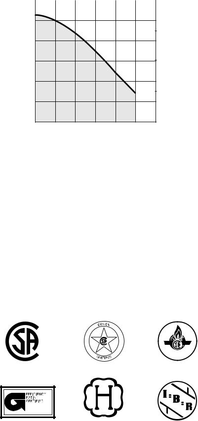
CIRCULATOR CURVE
TOTAL HEAD FEET
|
|
|
|
WATER FLOW |
M3/H |
|
|
|
|||||||
12 |
1 |
2 |
3 |
4 |
5 |
||||||||||
|
|
|
|
|
|
|
|
|
|
|
|
|
|
|
|
10
8
6
4
2
3 |
METERS |
|
2 |
||
TOTAL HEAD |
||
1 |
0 |
4 |
8 |
12 |
16 |
20 |
24 |
WATER FLOW GPM
WATER BOILER CIRCULATOR CURVE
|
ELECTRICAL DATA |
|
|
|
|
|
|
|
||||
|
|
|
|
|
|
|
|
|
|
|
|
|
ALL MODELS |
|
|
|
|
|
|
|
|
|
|
|
|
|
|
|
|
|
|
|
|
|
|
|
|
|
Voltage—Hertz—Phase |
|
|
|
|
|
|
115 — 60 — 1 |
|
|
|
||
|
|
|
|
|
|
|
|
|
|
|
|
|
Minimum Branch Circuit Wire Size (AWG) |
|
|
|
|
|
|
14 |
|
|
|
|
|
Maximum Fuse Size (Amps) |
|
|
|
|
|
|
15 |
|
|
|
|
|
Control Circuit Power Available |
|
|
|
|
|
|
40va–@ 24v |
|
|
|
||
STANDARD BOILER WARRANTIES (Yrs) |
|
|
|
|||||||||
|
|
|
|
|
|
|
|
|
|
|
|
|
MODEL |
|
BW1 |
|
BW2 |
BW3 |
BW4 |
|
BW5 |
|
BW9 |
BS1 |
BS2 |
|
|
|
|
|
|
|
|
|
|
|
|
|
Circulator Pump |
|
3 |
|
3 |
3 |
3 |
|
3 |
|
3 |
— |
— |
|
|
|
|
|
|
|
|
|
|
|
|
|
Vent Damper |
|
5 |
|
5 |
— |
— |
|
— |
|
— |
5 |
5 |
|
|
|
|
|
|
|
|
|
|
|
|
|
Heat Exchanger Section Assembly (Non-prorated) |
|
20 |
|
20 |
20 |
20 |
|
20 |
|
15 |
12 |
12 |
|
|
|
|
|
|
|
|
|
|
|
|
|
Oil Burner |
|
— |
|
— |
— |
3 |
|
3 |
|
— |
— |
— |
|
|
|
|
|
|
|
|
|
|
|
|
|
®
CERTIFIED
ama |
®
ASME
—4—
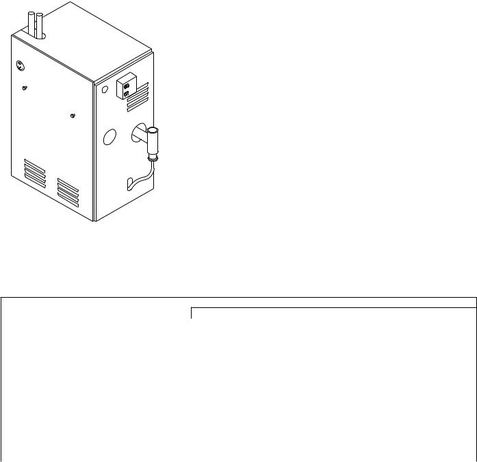
MODELS BW9
The BW9 is a gas fired direct vent condensing hot water boiler with cast aluminum heat exchanger sections. A revolutionary cast aluminum heat exchanger means better heat transfer and thermal storage than similarly sized cast iron boiler, which results in higher efficiency. The heating system water absorbs large amounts of heat from the cast aluminum heat exchanger, cooling the flue gases and causing condensation. Sealed combustion, premix gas burner, and low flame temperature means drastically reduced CO and NOx emissions, which contribute to a cleaner and healthier environment.
The BW9, unlike normal residential atmospheric and induced draft boilers, takes its combustion air directly from the outdoors (sealed combustion) and does not compete with building occupants for fresh air. Sealed combustion (also known as “direct vent”) is the safest and best way to obtain plenty of clean combustion air. The induced draft fan draws in the outside combustion air, then takes the cooler flue gases from the heat exchanger and provides a positive removal of the flue gases from the building through inexpensive and readily available PVC and CPVC pipes.
FEATURES
RANGE OF CAPACITIES—Three sizes ranging from 50,000 through 100,000 Btuh input.
COMPLETELY PACKAGED—Each boiler is completely assembled, including all controls (except room thermostat). All necessary wiring is factory installed. The boiler is ready for gas piping, room thermostat, and electrical power connections as shipped. Circulator is shipped pre-wired with 6 ft bx conduit for easy installation for supply side pumping.
VENTING—This boiler is direct vented with PVC and CPVC pipe. See the Installation Instructions for common venting requirements.
ALUMINUM SECTIONS—These sections speed heat transfer to the boiler water. With faster thermal response, greater comfort and economy are achieved.
PRE-MIX BURNER—Provides quiet operation and improved combustion efficiency.
CONTROLS—Integrated Boiler Control provides safe, dependable operation of burners. Factory-installed safety components provide maximum safety against overheating, pressure buildup, and low-water operation.
SECTIONS TESTED—Each section is hydrostatically tested to 50 psig. Individual sections are tested to 125 psig at factory. Assembled sections are tested to 75 psig at the factory. The maximum allowable pressure is 50 psig for hot water boilers.
PROPANE CONVERTIBLE—With factory approved conversion kit accessory.
WARRANTY—The aluminum sections are covered by a limited 15-year warranty on the entire assembly. Circulator pump is covered by a limited 3-year warranty. All other parts are covered by a 1-year limited warranty.
SPECIFICATIONS
UNIT SIZE |
050 |
075 |
100 |
|
Sections |
|
|
1 |
|
|
|
GAS CONTROLS |
|
|
|
|
|
|
|
|
|
|
|
|
|
Gas Valve |
|
|
Honeywell |
|
|
|
Inlet Size |
In. |
|
1/2 |
|
|
|
Ignition |
|
|
Hot Surface Ignition |
|
|
|
Burner—Stainless/Titanium Alloy |
|
|
1 |
|
|
|
|
|
|
|
|
|
|
Burner Orifice |
No. |
0.0615 |
#48 |
#44 |
|
|
CONTROLS |
|
|
|
|
|
|
|
|
|
|
|
|
|
Limit Control Range |
°F |
|
100-200 |
|
|
|
|
|
|
|
|
|
|
Pressure Relief Valve Setting |
Psig |
|
30 |
|
|
|
|
|
|
|
|
|
|
Integrated Boiler Control |
|
|
UTEC factory installed |
|
|
|
|
|
|
|
|
|
|
CIRCULATOR |
|
|
|
|
|
|
|
|
|
|
|
|
|
Taco |
Model |
|
007 |
|
|
|
Full Load Amps |
|
|
2.0 AMPS/330 WATTS |
|
|
|
|
|
|
|
|
|
|
Flange Size FPT |
In. |
|
1-1/4 |
|
|
|
|
|
|
|
|
|
—5—
 Loading...