

Page 1
CONDENSING GAS FURNACE
Owner’s Manual
NOTE TO INSTALLER:
THIS MANUAL MUST BE LEFT WITH THE
EQUIPMENT USER.
USER: PLEASE READ ALL INSTRUCTIONS
IN THE MANUAL AND RETAIN ALL
MANUALS FOR FUTURE REFERENCE.
!
WARNING
FIRE OR EXPLOSION HAZARD
Failure to follow warnings could result in personal injury,
death, or property damage.
Do not store or use gasoline or other flammable vapors and
liquids in the vicinity of this or any other appliance.
WHAT TO DO IF YOU SMELL GAS
--Do not try to light any appliance.
--Do not touch any electrical switch; do not use any phone
in your building.
--Leave the building immediately.
--Immediately call your gas supplier from a nearby phone.
Follow the gas supplier’s instructions.
--If you cannot reach your gas supplier, call the fire
department.
Installation and service must be performed by a qualified
installer, service agency or the gas supplier.
!
WARNING
CARBON MONOXIDE POISONING HAZARD
Failure to follow this warning could result in personal injury
and/or death.
Carbon Monoxide is invisible, odorless, and toxic! Install a
carbon monoxide alarm in your home, even if you do not
own a gas appliance. Locate the carbon monoxide alarm in
the living area of your home and away from gas appliances
and doorways to attached garages. Follow the alarm
manufacturer’s instruction included with the alarm.
A11264
!
WARNING
ELECTRICAL OPERATION HAZARD
Failure to follow this warning could result in personal injury,
death, or property damage.
Do not use this furnace if any part has been under water. A
flood--damaged furnace is extremely dangerous. Attempts to
use the furnace can result in fire or explosion. A qualified
service agency should be contacted to inspect the furnace and
to replace all gas controls, control system parts, and electrical
parts that have been wet, or the entire furnace if deemed
necessary.
Page 2
TABLE OF CONTENTS
WELCOME TO A NEW GENERATION OF COMFORT 2....
FURNACE COMPONENTS 3...........................
SAFETY CONSIDERATIONS 4.........................
BEFORE STARTING YOUR FURNACE 5.................
STARTING YOUR FURNACE 5.........................
SHUTTING DOWN YOUR FURNACE 7..................
PERFORMING ROUTINE MAINTENANCE 8.............
FILTERING OUT TROUBLE 9..........................
COMBUSTION AREA AND VENT SYSTEM 11...........
WINTERIZATION 13..................................
A CHECK--UP CHECKLIST 13..........................
BEFORE YOU REQUEST A SERVICE CALL 13...........
INSTALLATION DATA 14.............................
WELCOME TO TODAY’S GENERATION
OF COMFORT
Congratulations! In light of rising energy costs, a 90+% AFUE
Condensing Gas Furnace from Bryant Heating & Cooling Systems
is among the soundest investments today’s homeowner can make.
Your new furnace is truly a triumph of technology in home
heating. A revolutionary design employs two heat exchangers to
“squeeze” out the maximum amount of heat from the fuel
consumed. In fact, your new furnace is so efficient, over 90%* of
the heat generated during combustion is captured and delivered
inside your home.
This furnace is among the safest, most dependable,
energy--efficient furnaces you can buy today. We are proud of the
technological advances incorporated into the design of this furnace.
With only minimal care, your new furnace will deliver many years
of money-- saving home comfort and enjoyment. Spend just a few
minutes with this manual to learn the operation of your new
furnace and the small amount of maintenance it takes to help keep
it operating at peak efficiency year after year.
* The output capacity and any representations of efficiency for this furnace
are based on standard U.S. Department of Energy test procedures.
I
G
S
E
N
D
C
E
D
CERTIFIED
E
R
I
T
F
I
Use of the AHRI Certified TM Mark indicates a
manufacturer’s participation in the program. For
verification of certification for individual products,
go to www.ahridirectory.org.
A11264
Always Ask For
2
Page 3
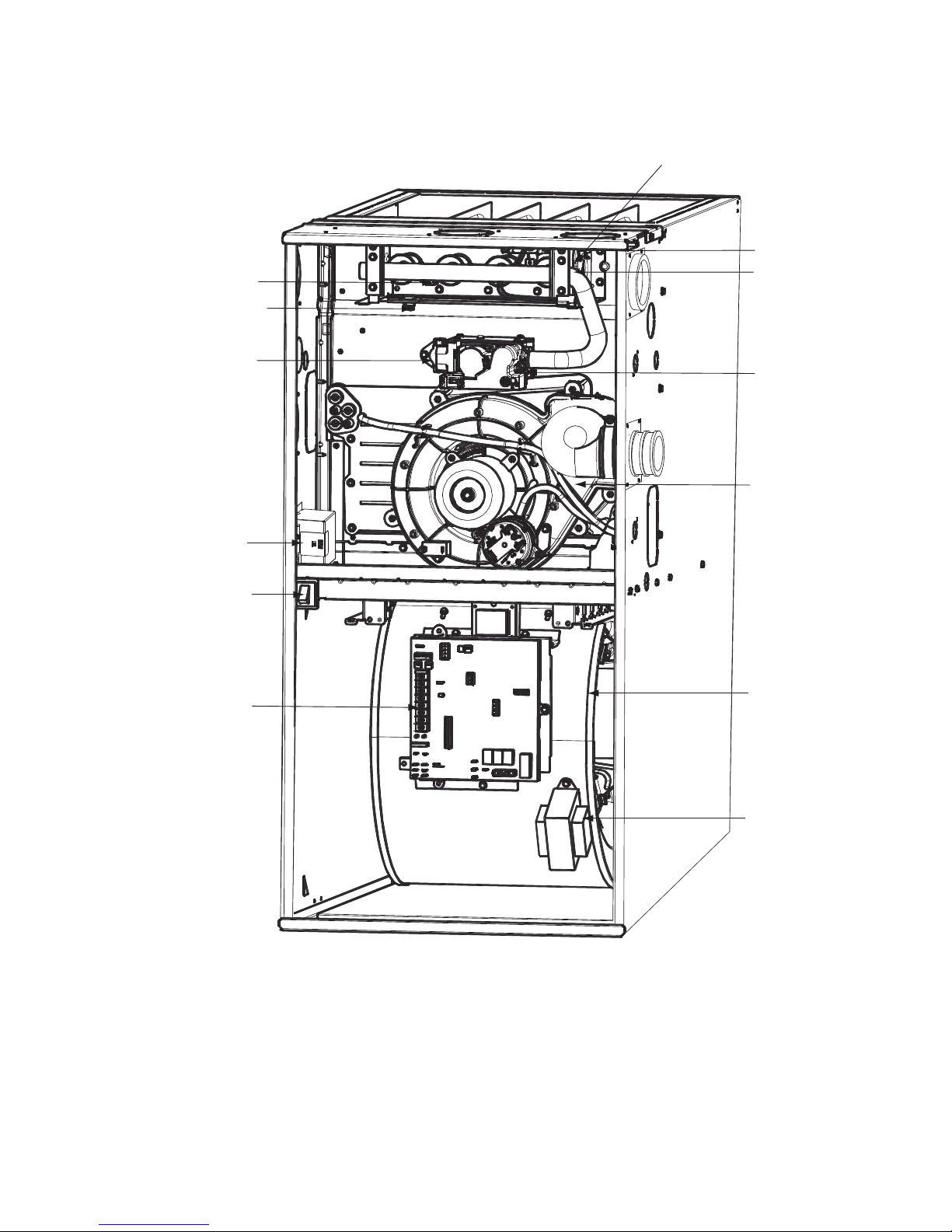
FURNACE COMPONENTS
(Furnace shown in upflow position; may be used in downflow or horizontal orientation or applications.
MANUAL RESET
LIMIT SWITCH
FLAME
SENSOR
MANUAL RESET
LIMIT SWITCH
HOT SURFACE
IGNITER
GAS BURNER
GAS VALVE
OPERATING INSTRUCTIONS
NOT SHOWN (LOCATED ON
FURNACE DOOR, SEE
INFORMATION BOOKLET
LOCATION FIGURE).
ELECTRICAL JUNCTION
BOX (IF REQUIRED,
LOCATION MAY VARY)
BLOWER DOOR
SAFETY SWITCH
FURNACE
CONTROL
BOARD
MAIN LIMIT SWITCH
(BEHIND GAS VALVE)
INDUCER MOTOR
ASSEMBLY
BLOWER AND
MOTOR
CAPACITOR/
POWER CHOKE
RATING PLATE NOT SHOWN
(LOCATED ON BLOWER DOOR)
REPRESENTATIVE DRAWING ONLY, SOME MODELS MAY VARY IN APPEARANCE.
A11316
Fig. 1 -- Furnace Components
3
Page 4
SAFETY CONSIDERATIONS
Installing and servicing of heating equipment can be hazardous due
to gas and electrical components. Only trained and qualified
personnel should install, repair, or service heating equipment.
Untrained personnel can perform basic maintenance functions such
as cleaning and replacing air filters. All other operations must be
performed by trained service personnel. Observe safety precautions
in this manual, on tags, and on labels attached to the furnace and
other safety precautions that may apply.
Recognize safety information. This is the safety--alert symbol
When you see this symbol on the furnace and in instructions or
manuals, be alert to the potential for personal injury.
Understand the signal words DANGER, WARNING, CAUTION,
and NOTE. DANGER, WARNING, and CAUTION are used with
the safety--alert symbol. DANGER identifies the most serious
hazards which will result in severe personal injury or death.
WARNING signifies hazards which could result in personal injury
or death. CAUTION is used to identify unsafe practices which
may result in minor personal injury or product and property
damage. NOTE is used to highlight suggestions which will result
in enhanced installation, reliability, or operation.
To minimize the possibility of serious personal injury, fire, damage
to your furnace, or improper operation, carefully follow these
safety rules which apply to both direct--vent and non--direct vent
applications:
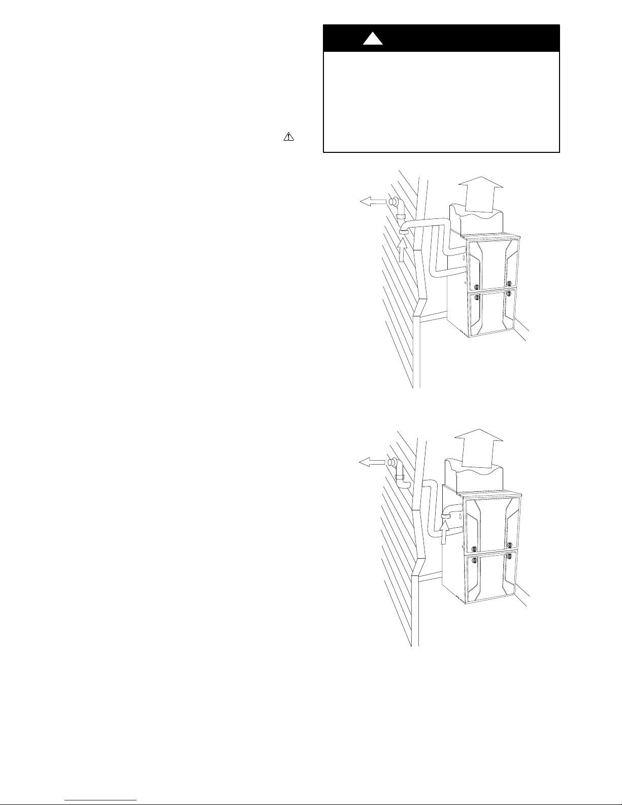
S Your new gas furnace may have been installed in one of two
ways, as a direct--vent (2--pipe--Fig. 2) application or as a
non--direct vent (1--pipe--Fig. 3) application.
S In a direct--vent (2--pipe) application, your furnace uses air
from outside the home for combustion and vents flue gas to the
outdoors. This type of application will have two pipes running
from the furnace to the outdoors. In some cases, the inlet air pipe
may be located in an area that has access to outdoor air, such as
an attic. In all cases, the outlet vent pipe must be routed to the
outdoors. (See Fig. 2.) In this application, the vent and
air--intake pipes must terminate outside the structure and must
not be obstructed in any way. Do not block or obstruct air
openings on furnace or spaces around furnace.
S In a non--direct vent (1--pipe) application, your furnace uses
air from adjacent to the furnace for combustion and vents flue
gas to the outdoors. This type of application will have only one
pipe running from the furnace to the outdoors. (See Fig. 3.) The
other pipe will terminate in the same space as the furnace and is
the source of combustion air for your furnace. Therefore, the
furnace must not be enclosed in an airtight room or be sealed
behind solid doors. It must have adequate airflow for efficient
combustion and safe ventilation. Do not obstruct the
combustion-- air pipe in any way. The vent pipe must terminate
outside the structure and must not be obstructed in any way. Do
not block or obstruct air openings or space around furnace.
!
WARNING
FIRE OR EXPLOSION HAZARD
Failure to follow warnings could result in personal injury,
death, or property damage.
Keep insulation clear of furnace and maintain clearances
shown on unit clearance label.
Do not keep combustible materials, gasoline, and other
.
flammable liquids or vapors around your furnace.
A11258
Fig. 2 -- Exterior Vent Pipes
A11259
Fig. 3 -- Interior Combustion -- Air Pipe
4
Page 5
!
WARNING
FIRE OR EXPLOSION HAZARD
Failure to follow this warning could result in personal injury,
death, or property damage.
Do not keep combustible materials, gasoline, and other
flammable liquids or vapors around your furnace.
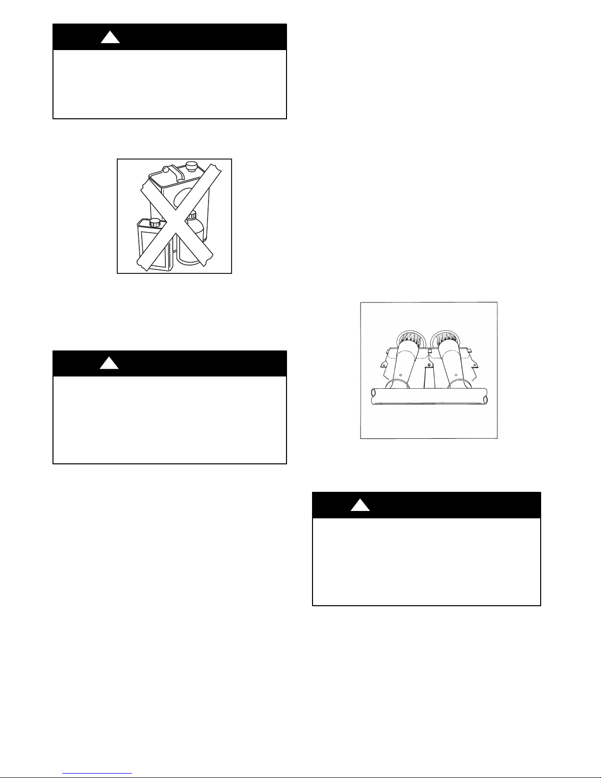
S Keep the area around your furnace clear and free of combustible
materials, gasoline, and other flammable liquids and vapors.
A92182
Fig. 4 -- NO combustible materials near furnace
S Should the gas supply fail to shut off or if overheating occurs,
shut off the gas valve to the furnace before shutting off electrical
supply.
This furnace contains SAFETY DEVICES which must be
MANUALLY RESET. If the furnace is left unattended for an
extended period of time, have it checked periodically for proper
operation. This precaution will prevent problems associated with
no heat, such as frozen water pipes, etc. See “Before You Request
a Service Call” section in this manual.
BEFORE STARTING YOUR FURNACE
Examine the furnace installation to determine that:
1. All flue gas carrying areas external to the furnace (i.e. chimney, vent connector) are clear and free of obstructions.
2. The vent connector is in place, slopes upward and is physically sound without holes or gaps.
3. The return--air duct connection(s) is physically sound, is
sealed to the furnace casing, and terminates outside the
space containing the furnace.
4. The physical support of the furnace is sound without sagging cracks, gaps, etc. around the base.
5. There are no obvious signs of deterioration of the furnace.
6. The burner flames are in good adjustment, See Fig. 5 (by
comparison with pictorial sketches or drawings of the main
burner flame).
S Do not cover the furnace, store trash or debris near it, or in any
way block the flow of fresh air to the unit.
!
CAUTION
UNIT OPERATION HAZARD
Failure to follow this caution may result in intermittent unit
operation.
For proper and safe operation the furnace needs air for
combustion and ventilation. Do not block or obstruct air
openings on the furnace, air opening to the area in which the
furnace is installed, and the space around the furnace.
In addition to the safety rules above, make sure that the following
combustion-- air requirements are met for non-- direct vent
applications:
S Combustion air must be clean and uncontaminated with chlorine
or fluorine. These compounds are present in many products
around the home, such as: water softener salts, laundry bleaches,
detergents, adhesives, paints, varnishes, paint strippers, waxes,
and plastics.
S Make sure the combustion air for your furnace does not contain
any of these compounds. During remodeling be sure the
combustion air is fresh and uncontaminated. If these compounds
are burned in your furnace, the heat exchangers may deteriorate.
S A furnace installed in an attic or other insulated space must be
kept free and clear of insulating material. Examine the furnace
area when the furnace is installed or when insulation is added.
Some insulation materials may be combustible.
A92330
Fig. 5 -- Burner Flame Adjustment
STARTING YOUR FURNACE
!
WARNING
FIRE AND EXPLOSION HAZARD
Failure to follow this warning could result in personal
injury, death or property damage.
Should the gas supply fail to shut off or if overheating
occurs, turn off the manual gas valve to the furnace
BEFORE turning off the electrical supply and install
lockout tag.
Instead of a continuously burning pilot flame which wastes
valuable energy, your furnace uses an automatic, hot surface
ignition system to light the burners each time the thermostat signals
the furnace to start.
Follow these important safeguards:
S Never attempt to manually light the burners with a match
or other source of flame.
5
Page 6
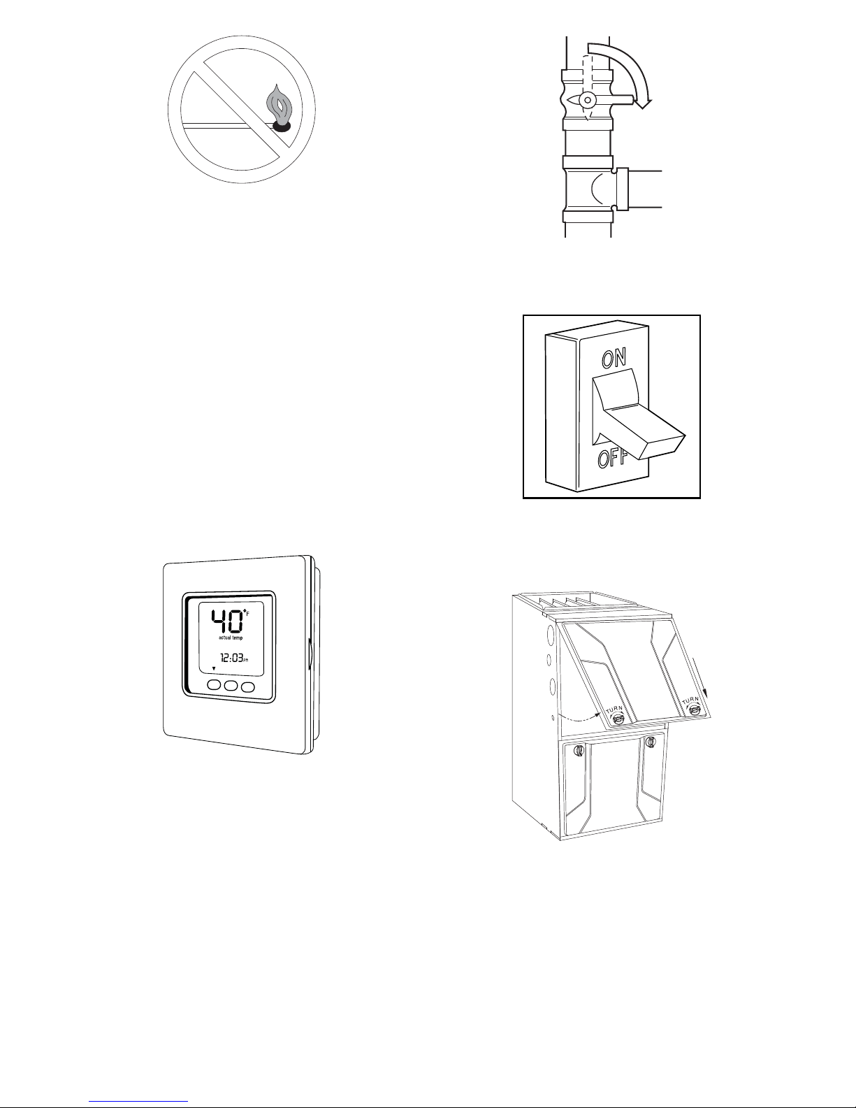
Fig. 6 -- Do Not Light Burner with Match
A92319
C
L
O
S
E
S Read and follow the operating instructions on inside of
main furnace door, especially the item that reads as follows: (See Fig. 31.)
“Wait 5 minutes to clear out any gas. Then smell for gas,
including near the floor. If you smell gas, STOP! Fol-
low “B” in the safety information on furnace label. If you
don’t smell gas, go to the next step.”
S If a suspected malfunction occurs with your gas control
system, such as the burners do not light when they
should, refer to the shutdown procedures on inside of
main furnace door, or in the “Shutting Down Your Furnace” section and call your dealer as soon as possible.
S CHECK AIR FILTER: Before attempting to start your
furnace, be sure the furnace filter is clean and in place.
See “Performing Routine Maintenance” section in this
manual. Do not run the furnace without a filter in place.
Then proceed as follows:
STEPS FOR STARTING YOUR FURNACE
1. Set your room thermostat to the lowest temperature setting
and set the “MODE” to “OFF.”. See Fig. 7.
A06188
Fig. 8 -- Close Valve
3. Turn OFF electrical supply to the furnace. See Fig. 9.
A92185
Fig. 9 -- Turn Off Electrical Supply
4. Remove the main furnace door. See Fig. 10.
Fig. 7 -- Lowest Temperature Setting
2. Close the external manual gas valve. See Fig. 8.
A09564
A11260
Fig. 10 -- Remove Main Furnace Door (Upflow Configuration)
5. Turn the control switch on the gas control to the OFF position
and wait five minutes. See Fig. 11. Thensmellfor gas, including near the floor. If you smell gas, STOP! Follow “B” on furnace label. If you don’t smell gas, go to next step.
6
Page 7
CONSULT
MANUAL
BEFORE
ADJUSTING
GAS
PRESSURE
NAT.
GAS
TWO-STAGE GAS CONTROL
A11292
SINGLE-STAGE GAS CONTROL
ON
OFF
GAS CONTROL SWITCH
SHOWN IN “OFF” POSITION
MODULATING GAS CONTROL
GAS CONTROL SWITCH
SHOWN IN “OFF” POSITION
Fig. 11 -- Control Switch to OFF
6. After waiting five minutes, turn control switch on the gas control to the ON position. Turn the control switch to ON. See
Fig. 12.
SINGLE-STAGE GAS CONTROL
MODULATING GAS CONTROL
ON
OFF
GAS CONTROL SWITCH
SHOWN IN “ON” POSITION
GAS CONTROL SWITCH
SHOWN IN “ON” POSITION
TWO-STAGE GAS CONTROL
CONSULT
MANUAL
BEFORE
ADJUSTING
GAS
PRESSURE
NAT.
GAS
A11291
Fig. 12 -- Control Switch to ON
7. Replace main furnace door. See Fig. 13.
A11261
Fig. 13 -- Furnace Door Replaced (Upflow Configuration)
8. Turn ON the electrical supply to the furnace and wait one
minute. See Fig. 14.
A92359
Fig. 14 -- Turn on Electrical Supply
9. Open the external manual gas valve. See Fig. 15.
O
P
E
N
A06189
Fig. 15 -- Open Valve
10. Set the room thermostat “MODE” to “HEAT” and adjust the
setpoint to a temperatureslightlyabovethe room temperature.
This will automatically signal the furnace to start.
11. When the furnace receives the start signal, the combustion air
draft inducer is started. When the pressure switch senses that
thereis sufficient combustion air, the hot surfaceigniter is energized.
Afterthe hotsurface igniteris heated for about20 seconds,the
gas valve permits gas to flow to the main burners. After ignition and a time delay of up to 60 seconds, the furnace blower
will start. Variable--capacity furnaces start at low speed until
the control makes the necessary adjustments to operate the
blower at either the low-- or high-- heat speed.
NOTE: If the main burners fail to ignite after four attempts, the
furnace control system will lock out. If lockout occurs, main
burners fail to light, or blower does not come on, shut down the
furnace and call your dealer for service.
12. Set your thermostat to the temperature that satisfies your
comfort requirements. SUGGESTION: Setting the thermostat back a few degrees—and compensating for the difference with warmer clothing—can make a big difference in
your fuel consumption on extremely cold days. The few degrees at the top of your thermostat “comfort level” are the
most costly degrees to obtain.
When the room temperature drops below the temperature selected
on the thermostat, the furnace will switch on automatically. When
the room temperature reaches the setting selected on the thermostat,
the furnace will be automatically switched off.
Continuous Fan Operation --Some thermostats have a “FAN”
switch with two selections: AUTO and ON. When the thermostat is
set on AUTO, the furnace blower cycles on and off, controlled by
the thermostat. In ON position, the furnace blower runs
continuously. Continuous fan keeps the temperature level in your
home more evenly balanced. It also continuously filters the indoor
air.
On all but the base series furnace, the blower speed can be
increased or decreased if desired due to change of seasons, large
7
Page 8
gatherings in your home, etc. Simply change your FAN from ON
to OFF for 1 to 3 seconds (or AUTO depending on your
thermostat), and then return to ON. The blower will switch to the
next higher speed. There are at least three speeds to choose from.
If the blower is running on its highest speed, a request to change
will direct the blower to return to its lowest speed.
SHUTTING DOWN YOUR FURNACE
Should you need to shut down your furnace for service or
maintenance, you will need to turn the furnace off. The following
procedures must be followed:
1. Set your room thermostat to the lowest temperature setting
andsetthe“MODE”to“OFF.”SeeFig.16.
A09564
Fig. 16 -- Lowest Temperature Setting
2. Close the external manual gas valve. See Fig. 17.
C
L
O
S
E
CONSULT
MANUAL
BEFORE
ADJUSTING
GAS
PRESSURE
NAT.
GAS
TWO-STAGE GAS CONTROL
A11292
SINGLE-STAGE GAS CONTROL
ON
OFF
GAS CONTROL SWITCH
SHOWN IN “OFF” POSITION
MODULATING GAS CONTROL
GAS CONTROL SWITCH
SHOWN IN “OFF” POSITION
Fig. 19 -- Control Switch to OFF
5. Turn control switch on the gas control to “OFF” position.
See Fig. 19.
6. Replace main furnace door. See Fig. 13.
7. If the furnace isbeing shut down because ofa malfunction, call
your dealer as soon as possible.
!
CAUTION
UNIT AND PROPERTY DAMAGE HAZARD
Failure to follow this caution may result in unit component or
property damage.
Furnace is not to be installed, operated, and then turned off
and left turned off in an unoccupied structure during winter.
See “Winterization” procedures in this manual.
Fig. 17 -- Close the External Manual Valve
3. Turn off electrical supply to the furnace. See Fig. 18.
Fig. 18 -- Turn Off Electrical Supply
A06188
A92185
PERFORMING ROUTINE MAINTENANCE
NOTE: The qualified installer or agency must use only
factory--authorized replacement parts, kits, and accessories when
modifying this product.
Installing and servicing of heating equipment can be hazardous due
to gas and electrical components.
Only trained and qualified personnel should install, repair, or
service heating equipment. Untrained personnel can perform basic
maintenance functions such as cleaning and replacing air filters.
All other operations must be performed by trained service
personnel. Observe safety precautions in this manual, on tags, and
on labels attached to the furnace and other safety precautions that
may apply.
With proper maintenance and care, your furnace will operate
economically and dependably. Instructions for basic maintenance
are found on this and the following pages. However, before
beginning maintenance, follow these safety precautions:
!
WARNING
ELECTRICAL SHOCK HAZARD
Failure to follow this warning could result in personal
injury or death.
Turn off electrical power supply to your furnace and
install lockout tag before removing the access doors to
service or perform maintenance.
4. Remove main furnace door. See Fig. 10.
8
Page 9
!
CAUTION
CUT HAZARD
Failure to follow this caution may result in personal injury.
Although special care has been taken to minimize sharp
edges, be extremely careful when handling parts or reaching
into the furnace. Wear safety glasses, gloves, and
appropriate protective clothing.
FILTERING OUT TROUBLE
NOTE: The manufacturer has specified filters which will enable
your furnace to provide lasting comfort and efficiency throughout
its life. Contact your dealer to help you choose filters for your
furnace that both collect dirt before it enters your furnace, as well
as provide a low resistance to circulating air. A void filters that
report high cleaning efficiencies, but do not allow air to pass easily
through them.
!
CAUTION
UNIT PERFORMANCE HAZARD
Failure to follow this caution may result in unit component
damage.
Never operate your furnace without a filter in place. Doing
so may damage the furnace blower motor. An
accumulation of dust and lint on internal parts of your
furnace can cause a loss of efficiency.
a. Remove filter cabinet door. (See Fig. 21 and 22.)
NOTE: It maybe necessary to remove one thumbscrew.
b. Slide air filter out of furnace. Keep dirty side up (if
dirty) to avoid spilling dirt. See Fig. 23 and 24.
3. Inspect the filter. If torn replace it.
NOTE: If a washable filter was supplied with the furnace and has
been replaced by:
S Ddisposable media filter---- Do not clean. If dirty, replace
only with media filter having the same part number and
size. Install with airflow direction arrow pointing towards blower.
S Electronic Air Cleaner (EAC), refer to the EAC Owner’s
Manual for maintenance information.
4. If washable filter, wash filter (if dirty) in a sink, bathtub, or
outside with a garden hose. Always use cold tap water. A
mild liquid detergent may be used if necessary. Spray water
through filter in the opposite direction of airflow. Allow filter to dry.
5. Reinstall clean air filter.
6. Turn on electrical supply to the furnace.
If your furnace air filter needs to be replaced, be sure to use a
factory--authorized filter of the same size that was originally
specified. Use the filter tables and compare your furnace size with
the proper filter size.
!
CAUTION
PERSONAL INJURY HAZARD
Failure to follow this caution may result in personal injury.
Use care when cutting support rods in filters to protect against
flying pieces and sharp rod ends. Wear safety glasses, gloves,
and appropriate protective clothing.
A dirty filter will cause excessive stress on the furnace, heat
exchanger, and blower motor, and can cause it to overheat and
automatically shut down. The furnace filter should be checked
every four weeks and be cleaned or replaced if necessary.
If installed with factory--specified disposable media filter, check or
replace filter before each heating and cooling season. Replace
disposable media filter at least once a year.
If your furnace filter needs replacing, be sure to use the same size
and type of filter that was originally specified.
The air filter for the furnace may be located an external filter
cabinet attached to the side or bottom of the furnace casing. If the
air filter has been installed in another location, contact your dealer
for instructions. To inspect, clean and/or replace the air filter(s),
follow these steps:
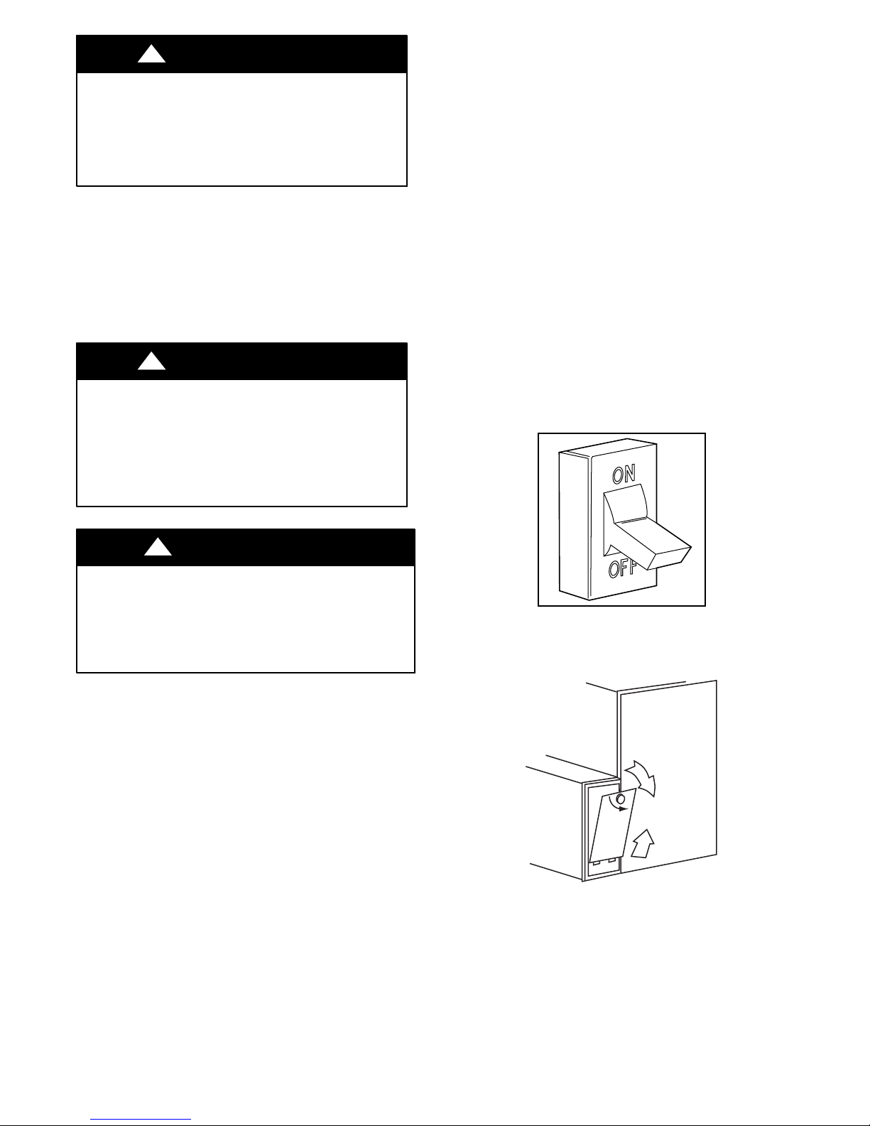
1. Turn off electrical supply to the furnace. See Fig. 20.
2. Remove air filter from the filter cabinet.
A92185
Fig. 20 -- Turn Off Electrical Supply
A00225
Fig. 21 -- Removal of Filter Cabinet Door from Side Blower
Cabinet
9
Page 10
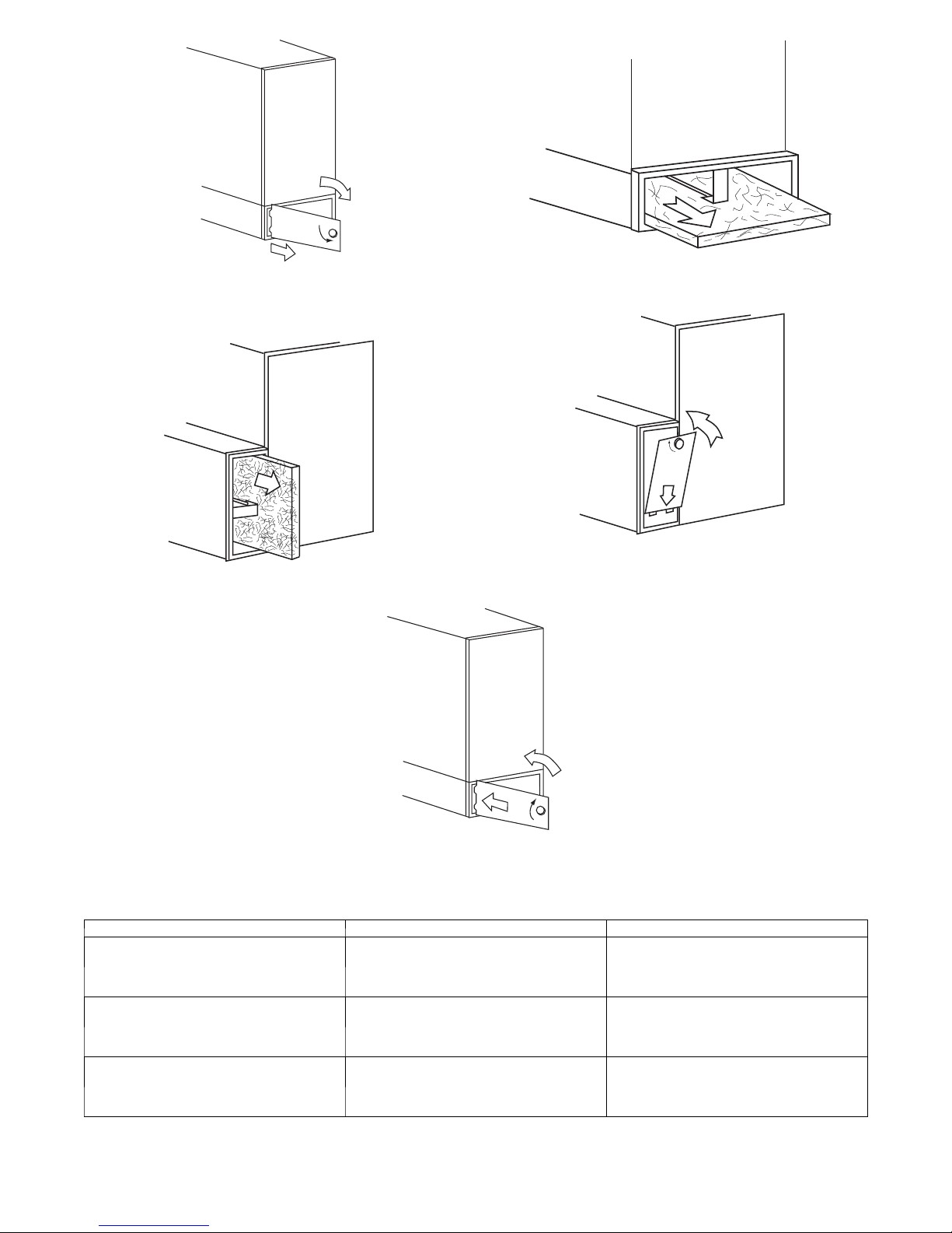
Fig. 22 -- Removal of Filter Cabinet Door from Bottom
Blower Cabinet
Fig. 23 -- Removal of Filter from Side Blower Cabinet
A00226
A00227
A00228
Fig. 24 -- Removal of Filter from Bottom Blower Cabinet
A00229
Fig. 25 -- Replacement of Filter Cabinet Door to Side Blower
Cabinet
Fig. 26 -- Replacement of Filter Cabinet Door to Bottom Blower Cabinet
FILTER CABINET HEIGHT --- IN (MM) F IL T E R S I Z E --- I N ( M M ) FILTER TYPE
16 (406)
20 (508)
24 (610)
* Filters with a side return --air may have a different filter size. Measure the filter to obtain the correct size.
{ Recommended to maintain air filter face vel ocity. See Product Data for part number.
Table 1 – Air Filter Located in Filter Cabinet
(1) 16 x 25 x 3/4*
(406 x 635 x 19) or
(1) 16 x 25 x 4---5/16
(406 x 635 x 110)
(1) 20 x 25 x 3/4*
(508 x 635 x 19) or
(1) 20 x 25 x 4---5/16
(508 x 635 x 110)
(1) 24 x 25 x 3/4*or
(610 x 635 x 19) or
(1) 24 x 25 x 4---5/16
(610 x 635 x 110)
10
A00230
Washable{
Washable{
Washable{
Page 11
COMBUSTION AIR AND VENT SYSTEM
HOT SURFACE
IGNITOR
!
WARNING
CARBON MONOXIDE POISONING HAZARD
Failure to follow this warning could result in personal injury
or death.
If holes are found or if the vent pipe is obstructed or is not
connected, toxic fumes can escape into your home. DO NOT
OPERATE YOUR FURNACE. Call your dealer for service.
!
CAUTION
UNIT OPERATION HAZARD
Failure to follow this caution may result in intermittent unit
operation.
For proper and safe operation the furnace needs air for
combustion and ventilation. Do not block or obstruct air
openings on the furnace, air opening to the area in which the
furnace is installed, and the space around the furnace.
Visually inspect the combustion area and vent system before each
heating season. Make sure that all PVC pipes leading into the
combustion area and vent are free from any cracks and sags. An
accumulation of dirt, soot, or rust can mean a loss of efficiency and
improper performance. Buildups on the main burners can cause
faulty firing. This “delayed ignition” is characterized by an
alarmingly loud sound.
Check the combustion--air intake adjacent to the furnace or outside
your home for blockage. Also check the vent pipe on the outside of
your home for blockage.
NOTE: If your furnace makes a loud noise when the main burners
are ignited, shut down the furnace and call your servicing dealer.
Use your flashlight and follow these steps for inspecting the
combustion area and vent system of your furnace:
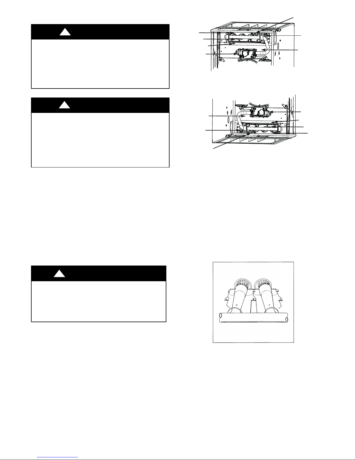
GAS BURNER
ASSEMBLY
FLAME
SENSOR
MANUAL RESET
LIMIT SWITCH
GAS VALVE
MANUAL RESET
LIMIT SWITCH
MAIN LIMIT SWITCH
(BEHIND GAS VALVE)
Fig. 27 -- Gas Burner Assembly (Upflow)
MAIN LIMIT SWITCH
(BEHIND GAS VALVE)
MANUAL RESET
LIMIT SWITCH
HOT SURFACE
IGNITOR
MANUAL RESET
LIMIT SWITCH
Fig. 28 -- Gas Burner Assembly (Downflow)
2. Inspect the gas burners, igniter area, and remainder of furnace for dirt, rust, soot or scale.
3. Inspect the combustion--air and vent PVC pipes for sags,
holes, cracks, water leaks, blockage or disconnections. Horizontal portions of vent pipe must slope downward toward
the furnace.
4. If your furnace is free of the above conditions,turn on electrical and gas supplies to the furnace.
5. Start your furnace and observe its operation. Watch the
burner flames to see if they are clear blue, almost transparent.. See Fig. 29. If you observe a suspected malfunction,
or the burner flames are not clear blue, call your dealer.
6. Replace main furnace door.
GAS VALVE
FLAME
SENSOR
GAS BURNER
ASSEMBLY
A11319
A11320
!
WARNING
CARBON MONOXIDE POISONING HAZARD
Failure to follow this warning could result in personal
injury or death.
If dirt, rust, soot, or scale accumulations are found, call
your dealer. Do not operate your furnace.
1. Turn off electrical supply and gas supply to the furnace and
remove the main furnace door. See Fig. 7, 8, 9, 10 and 11.
A92330
Fig. 29 -- Burner Flame Adjustment
11
Page 12
WINTERIZA TION
!
CAUTION
UNIT AND PROPERTY DAMAGE HAZARD
Failure to follow this caution may result in unit component or
property damage.
If the furnace is installed in an unconditioned space where the
ambient temperatures may be 32_ F(0_ C) or lower, freeze
protection measures must be taken to prevent minor property
or product damage.
Since the furnace uses a condensing heat exchanger, some water
will accumulate in the unit as a result of the heat transfer process.
Therefore, once it has been operated, it cannot be turned off and
left off for an extended period of time when temperatures will
reach 32_F(0_C) or lower unless winterized. Follow these
procedures to winterize your furnace:
!
CAUTION
UNIT COMPONENT DAMAGE HAZARD
Failure to follow this caution may result in damage to the
furnace and other property damage.
Do not use ethylene glycol (Automotive antifreeze coolant or
equivalent). Failure of plastic components may occur.
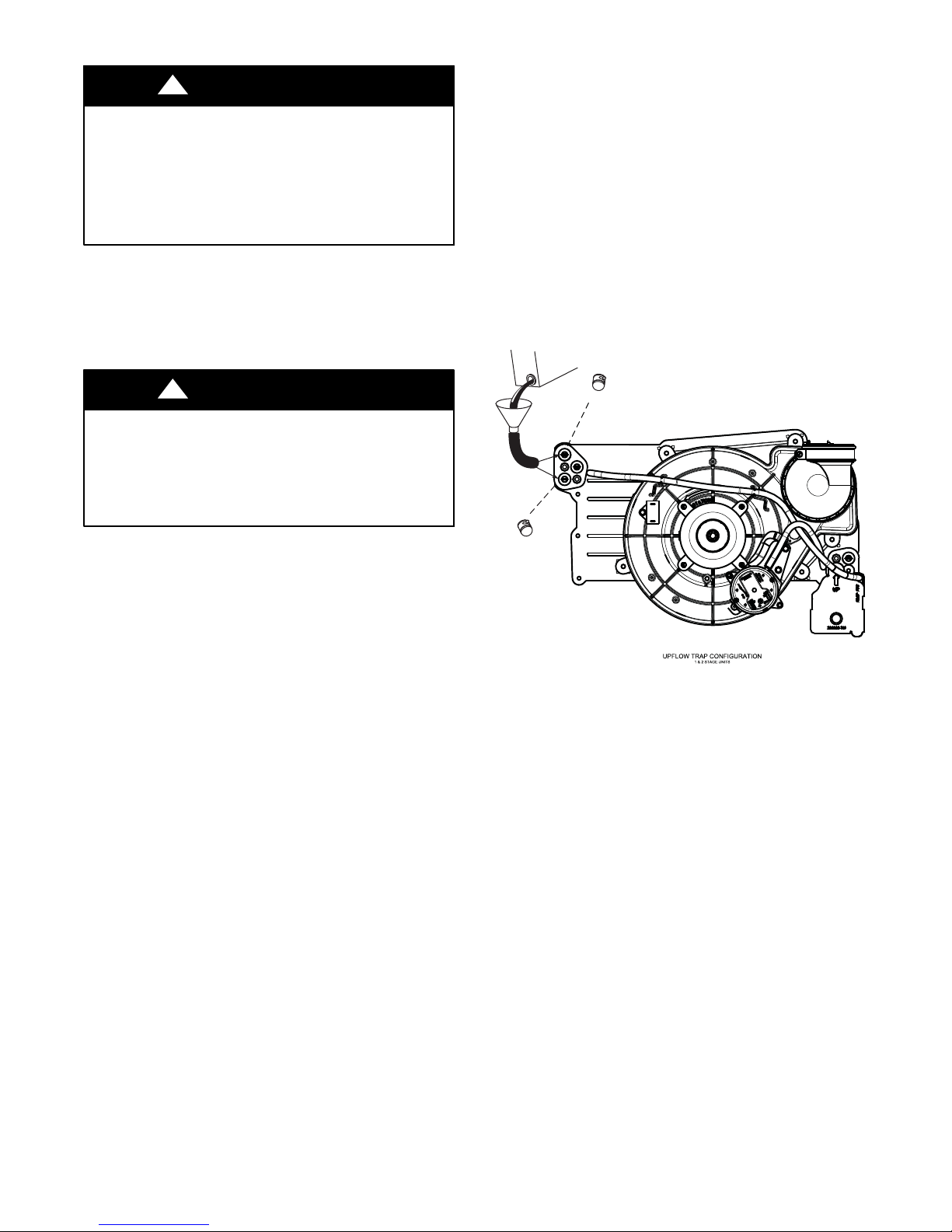
6. Insert a field supplied funnel into the tube.
7. Pour 1 quart of anti-freeze solution into the funnel/tube.
Antifreeze should run through the inducer housing, overfill
condensate trap and flow to an open drain.
8. If a condensate pump is used, check with pump
manufacturer to verify pump is safe for use with antifreeze
used. Allow pump to start and pump anti-freeze to open
drain.
9. Remove funnel and tube from collector box.
10. Replace plug in collector box.
11. Remove the other plug and repeat steps 4-- 10.
12. Replace main door.
13. When furnace is re-started, flush condensate pump with
clear water to check for proper operation before re-starting
furnace.
14. Propylene glycol need not be removed before re-starting
furnace.
1. Obtain propylene glycol (RV/swimming pool antifreeze or
equivalent).
2. Turn off gas and electrical supplies to your furnace.
3. Remove furnace control compartment door.
4. Remove one of the unused rubber plugs in the port on the
collector box opposite the condensate trap. See Fig 30.
5. Connect a field supplied 3/8-in. (9.5-mm) ID tube to the
open port on the collector box
A11315
Fig. 30 -- Winterizing Furnace
12
Page 13
A CHECK--UP CHECKLIST
Your furnace represents an important investment in your family’s
comfort and your home’s value. To keep it performing properly
and to prevent future problems, have a trained service specialist
give your furnace a professional check--up annually. The following
checklist can be used as a guideline to proper service:
S Inspect all flue gas passages, burners, heat exchangers, coupling
box(es), and inducer assembly.
S Inspect all combustion-- air and vent piping inside structure and
pipe terminations outside the structure.
S Check gas pipes leading to and inside of your furnace for leaks.
S Inspect and clean the blower motor and wheel.
NOTE: The inducer and blower motors are pre--lubricated and
require no additional lubrication. These motors can be identified by
the absence of oil ports on each end of the motor.
S Inspect and change or clean air filter(s) if necessary.
S Inspect all supply-- and return--air ducts for obstructions, air
leaks, and insulation. Remedy any problem when necessary.
S Inspect the return--air duct connection(s) at the furnace to ensure
it is physically sound, sealed to the furnace casing, and
terminates outside the space containing the furnace.
S Inspect electrical wiring, connections, and components for loose
connections.
S Perform an operational checkout to determine whether your
furnace is working properly and if it requires adjustments.
S Inspect all condensate drain tubes and condensate trap assembly
for leaks. The condensate removal system should be cleaned
annually by a qualified service agency. Refer to the Service and
Maintenance Instructions Guide for further information.
S Examine the physical support of the furnace. Support should be
sound with no cracks, sagging, gaps, etc. around the base.
S Check furnace for any obvious signs of deterioration.
S Ask your servicing dealer for further details about an economical
service contract that covers seasonal inspections.
FOR YOUR SAFETY READ BEFORE OPERATING
BEFORE YOU REQUEST A
“SERVICE CALL”
If your furnace is not operating or not performing properly,
you may save the expense of a service call by checking a few
things yourself before calling for service.
This furnace has a light emitting diode (LED) status code display
to aid the installer, service technician, or homeowner while
installing or servicing the unit. The LED code can be seen through
the view port in the blower access panel.
NOTE: Record the LED status code BEFORE removing the
blower access door or turning off 115-- v power to the furnace. See
the information booklet inside the main furnace door for a service
code legend. See Fig. 31.
For insufficient airflow:
S Check for dirty air filter(s).
S Check for blocked return--air or supply--air grilles. Be sure they
are open and unobstructed.
If problem still exists, call your dealer for service.
If furnace fails to operate:
Follow this checklist step by step, advancing to the next stop only
if furnace fails to start.
S Check thermostat for proper temperature. Is thermostat set above
room temperature?
S Is thermostat set to HEAT mode?
S Check fuses and circuit breakers. Is the electrical power supply
switch on?
S Is the manual shut--off valve in the gas supply pipe leading to
the furnace open?
NOTE: Turn off electrical supply before continuing with
checklist.
S Is control switch on gas valve in ON position? (Follow start--up
procedures if you must reset switch to ON position.)
S Check manual reset flame rollout switch located on the burner
box. See Furnace Components in Fig. 1. If furnace has
experienced high temperature conditions, this switch will shut
off the furnace. Reset it by pushing the button on the switch. If it
trips again, shut down the furnace and call for service. See
“Shutting Down Your Furnace” section in this manual.
S Check for obstructions around the vent termination.
If your furnace still fails to operate, call your service representative.
For your convenience, record the furnace product and serial
numbers on back page. Should you ever require service, you will
have ready access to the information needed by your service
representative.
Fig. 31 -- Information Booklet Location
A11318
13
Page 14
NOTE TO EQUIPMENT OWNER:
For your convenience, please record the model and serial numbers of your new equipment in the spaces
provided. This information, along with the installation data and dealer contact information will be helpful
should your system require maintenance or service.
FURNACE
Model # _____________________________________
Serial # ______________________________________
AIR CONDITIONER OR HEAT PUMP
Model # _____________________________________
Serial # _____________________________________
INDOOR COIL (Furnace Coil or Fan Coil)
Model # _____________________________________
Serial # _____________________________________
NOTE TO INSTALLER:
This manual must be left with the equipment owner.
INSTALLATION INFORMATION:
Date Installed ________________________________
DEALERSHIP CONTACT INFORMATION:
Company Name_______________________________
Address______________________________________
_____________________________________________
Phone Number _______________________________
Technician Name _____________________________
_____________________________________________
_____________________________________________
E2011 Bryant Heating & Cooling Systems D 7310 W. Morris St. D Indianapolis, IN 46231 Printed in U.S.A. Edition Date: 07/11
Manufacturer reserves the right to discontinue, or change at any ti me, specifications or designs without notice and without incurring obligations.
14
Catalog No. OM9GFB---01
Replaces: New
 Loading...