

Bryant 925SA Series, 925SA030040, 925SA042060, 925SA048080, 925SA048100 Product Data
...
925SA
PREFERREDt SERIES SINGLE--STAGE
4--WAY MULTIPOISE
CONDENSING GAS FURNACE, SERIES A
Product Data
A11264
The 925SA Multipoise SEER Boost Condensing Gas Furnace
features the single--stage Preferred™ System. The multi--tap ECM
blower motor is at the heart of the electrical efficiency provided by
this furnace. With an Annual Fuel Utilization Efficiency (AFUE)
of 96.2%, the Preferred single--stage gas furnace provides added
savings over standard gas furnaces. This Preferred Gas Furnace
features 4--way multipoise installation flexibility, and is available in
five model sizes. The 925SA can be vented for direct
vent/two--pipe, ventilated combustion air, or single--pipe
applications. A Bryant Preferred Control and Preferred Air
Conditioner or Heat Pump, can be used to form a complete
Preferred Series System. All units meet California Air Quality
Management District emission requirements. All sizes are design
certified in Canada.
STANDARD FEATURES
S Quiet operation. Compare for yourself at HVACpartners.com
S Ideal height 35” (889 mm) cabinet: short enough for taller coils,
but still allows enough room for service
S Preferred Features—match with the Preferred Control for
Preferred System benefits
S Silicon Nitride Perfect Light™ Hot Surface Igniter
S SmartEvap™ technology helps control humidity levels in the
home when used with a compatible humidity control system
S FanOnPlus™ technology allows control ofcontinuous fan
speed from a compatible thermostat
S External Media Filter Cabinet included
S 4--way multipoise design for upflow, downflow or horizontal
installation, with unique vent elbow and optional through-the--cabinet downflow venting capability
S Multi--tap ECM blower motor, single--speed inducer motor, and
single--stage gas valve
S Self--diagnostics
S Adjustable blower speed for cooling, continuous fan, and
dehumidification
S Aluminized--steel primary heat exchanger
S Stainless--steel condensing secondary heat exchanger
S Propane convertible (See Accessory list)
S Factory--configured ready for upflow applications
S Fully--insulated casing including blower section
S Convenient Electronic Air Cleaner and Humidifier connections
S Direct--vent/sealed combustion, single--pipe venting or
ventilated combustion air
S Installation flexibility: sidewall or vertical vent
S Residential installations may be eligible for consumer financing
through the Retail Credit Program
LIMITED WARRANTY*
S 10 year parts and lifetime heat exchanger limited warranty to the
original purchaser upon timely registration.
S Limited warranty period is five years for parts and twenty years
for the heat exchanger if not registered within 90 days of
installation.{
* For owner occupied, residential applications.
{Jurisdictions where warranty benefits cannot be conditioned on registra-
tion will receive registered limited warr anty benefits.
CERTIFIED
Use of the AHRI Certified TM Mark indicates a
manufacturer’s participation in the program. For
verification of certification for individual products,
go to www.ahridirectory.org.
1
Always Ask For

SPECIFICATIONS
Heating Capacity and Efficiency 030040 042060 048080 048100 066120
Input High Heat (BTUH) 40,000 60,000 80,000 100,000 120,000
Output High Heat (BTUH) 39,000 58,000 78,000 98,000 117,000
Efficiency AFUE % (ICS) 96.2 96.2 96.2 96.2 96.2
Certified Temperature
Rise Range ºF (ºC)
Airflow Capacity and Blower Data 030040 042060 048080 048100 066120
Certified External Static
Pressure (in. w.c.)
Airflow Delivery
@RatedESP(CFM)
Cooling Cap acity (tons)
@ 400, 350 CFM/ton
Direct-Drive Motor Type Electronically Commutated Motor (ECM)
Direct-Drive Motor HP 1/2 3/4 3/4 1 1
Motor Full Load Amps 6.8 8.4 8.4 10.9 10.9
RPM Rang e 600 - 1200
Speed Selections 5
Blower Wheel Dia x Width in. 11x7 11x8 11x8 11x10 11 x 11
Air Filtration System
Filter Used for Certified Watt Data
Electrical Data 030040 042060 048080 048100 066120
Input Voltage Volts-Hertz-Phase 115-60-1
Operating Voltage Range Min-Max 104-127
Maximum Input Amps Amps 8.1 9.7 9.7 12.2 12.2
Unit Ampacity Amps 11.0 13.0 13.0 16.1 16.1
Minimum Wire Size AWG 14 14 14 12 12
Maximum Wire Length
@ Minimum Wire Size
Maximum Fuse/Ckt Bkr
(Time-Delay Type Recommended)
Transformer Capacity (24vac output) 40 VA
External Control Power
Available
Controls 030040 042060 048080 048100 066120
Gas Connection Size 1/2” - NPT
Burners (Monoport) 2 3 4 5 6
Gas Valve (Redundant)
Gas C onversion Kit - Natural to Propane KGANP50011SP
Gas Conversion Kit - Propane to Natural KGAPN42011SP
Manufactured (Mobile) Home Kit KGAMH0301KIT
Ignition Device Silicon Nitride
Limit Control 165 180 170 160 160
Heating Blower Control (Heating Off-Delay) Adjustable: 90, 120, 150, 180 seconds
Cooling Blower Control (Time Delay Relay) 90 seconds
Communication System none
Thermostat Connections Y1, DHUM, G C W, Y/Y2, R
Accessory Connections EAC (115vac); HUM (24vac); 1-stg AC (via Y/Y2)
High Heat
Heating 0.10 0.12 0.15 0.20 0.20
Cooling 0.5 0.5 0.5 0.5 0.5
High Heat 695 1000 1360 1730 2125
Cooling 925 1505 1610 1720 2055
400 CFM/ton 2 3.5 4 4 5
350 CFM/ton 2.5 4 4.5 5 6
Feet 33 28 28 35 35
(M) (10.1) (8.5) (8.5) (10.7) (10.7)
Amps 15 15 15 20 20
Heating 24.3 VA
Cooling 34.6 VA
Manufacturer White Rogers™
Minimum Inlet Gas
pressure (in. W.C.)
Maximum Inlet Gas
pressure (in. W.C.)
40 - 70
(21-38)
KGAWF1606UFR KGAWF1306UFR KGAWF1406UFR KGAWF1506UFR KGAWF1506UFR
40 - 70
(21-38)
Factory Supplied Media Cabinet
40 - 70
(21-38)
FieldSuppliedFilter
4.5
13.6
40 - 70
(21-38)
40 - 70
(21-38)
2
MODEL NUMBER NOMENCLATURE
1 - 2
Family/Tier
92
91 - Legacy
92 - Preferred
98 - Evolution
3
Base Eff.
5
0 --- 90 AFUE
3 --- 93 AFUE
5 --- 95 AFUE
6 --- 96 AFUE
7 --- 97 AFUE
Htg. Stages
S - Single Stage
T - Two Stage
M - Modulating
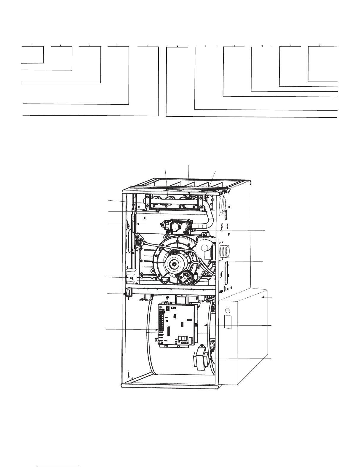
MANUAL RESET
ROLLOUT SWITCH
OPERATING INSTRUCTIONS
NOT SHOWN (LOCATED ON
MAIN FURNACE DOOR, SEE
OPERATING INSTRUCTIONS
INSIDE DOOR FIGURE).
ELECTRICAL JUNCTION
BOX (IF REQUIRED,
LOCATION MAY VARY)
4
S
FLAME
SENSOR
GAS VALVE
5
Major Series
A
Major Series
6 - 7
Clg. Cap.
30
24 - 800 CFM
30 - 1000 CFM
36 - 1200 CFM
42 - 1400 CFM
48 - 1600 CFM
54 - 1800 CFM
60 - 2000 CFM
66 - 2200 CFM
(@ 0.5” ESP)
Not all familes have these models.
8 - 10
Htg. Cap.
040
040=40,000 BTU
060=60,000 BTU
080=80,000 BTU
100=100,000 BTU
120=120,000 BTU
11
Motor
E
S - Standard
E - Energy Efficient
V - Variable Speed
FURNACE COMPONENTS
HOT SURFACE
GAS BURNER
IGNITER
MANUAL RESET
ROLLOUT SWITCH
12 - 13
Width
14
14 - 14.2”
17 - 17.5”
21 - 21.0”
24 - 24.5”
14
Voltage
A
Voltage
MAIN LIMIT SWITCH
(BEHIND GAS VALVE)
INDUCER MOTOR
ASSEMBLY
15
Features
--
L - Low NOx
16
Minor Series
A
A11165
BLOWER DOOR
SAFETY SWITCH
FURNACE
CONTROL
BOARD
RATING PLATE NOT SHOWN
(LOCATED ON BLOWER DOOR)
REPRESENTATIVE DRAWING ONLY, SOME MODELS MAY VARY IN APPEARANCE.
3
MEDIA CABINET
BLOWER AND
MOTOR
CAPACITOR/
POWER CHOKE
(IF USED)
A11408
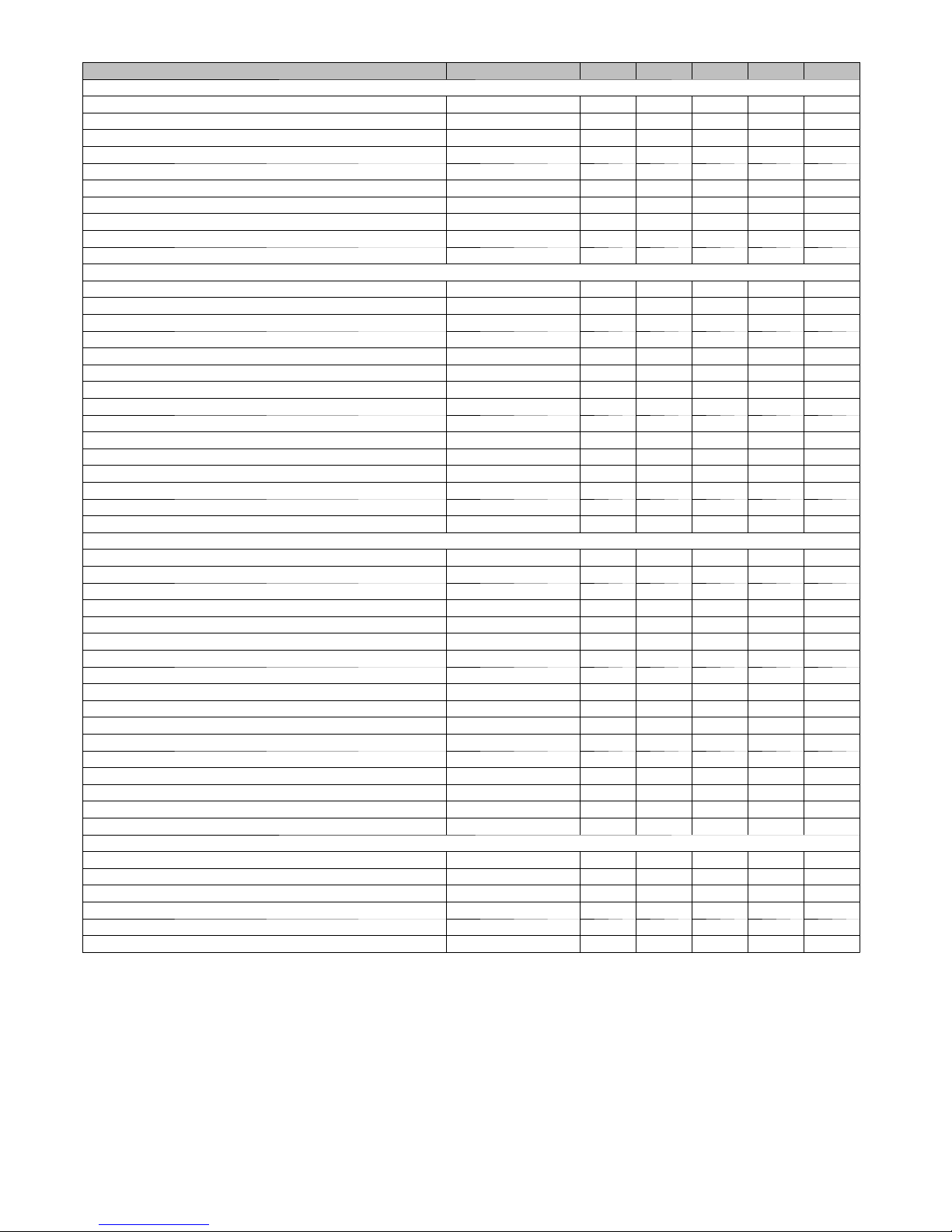
ACCESSORIES
DESCRIPTION PAR T NUM BER 030040 042060 048080 048100 066120
Venting, Drainage and Installation
Vent Kit - Through the Cabinet KGADC0101BVC X X X X X
Vent Terminal - Concentric - 2” (51 mm) KGAVT0701CVT X X X X N/A
Vent Terminal - Concentric - 3” (76 mm) KGAVT0801CVT N/A X X X X
Vent Terminal Bracket - 2” (51 mm) KGAVT0101BRA X X X X N/A
Vent Terminal Bracket - 3” (76 mm) KGAVT0201BRA N/A X X X X
CPVC to PVC Drain Adapters - 1/2” CPVC to 3/4” PVC KGAAD0110PVC X X X X X
Horizontal Trap Grommet - Direct Vent KGACK0101HCK X X X X X
Freeze Protect Kit - Heat Patch for Drain Trap KGAHT0201CFP X X X X X
Freeze Protect Kit - Heat Tape KGAHT0101CFP X X X X X
Furnace Base Kit for Combustible Floors KGASB0201ALL X X X X X
Gas Conversion
Mfg Home Kit - Single-stage KGAMH0601KIT X X X X X
GasCnvKit-NattoLP;Single-stage KGANP50011SP X X X X X
Gas Cnv Kit - LP to Nat; Single-stage KGAPN42011SP X X X X X
GasOrificeKit-#42(NatGas) KGAHA0150N42 X X X X X
GasOrificeKit-#43(NatGas) KGAHA0250N43 X X X X X
GasOrificeKit-#44(NatGas) KGAHA0350N44 X X X X X
GasOrificeKit-#45(NatGas) KGAHA0450N45 X X X X X
GasOrificeKit-#46(NatGas) KGAHA0550N46 X X X X X
GasOrificeKit-#47(NatGas) KGAHA1550N47 X X X X X
GasOrificeKit-#48(NatGas) KGAHA1650N48 X X X X X
Gas Orifice Kit - #54 (LP) KGAHA0650P54 X X X X X
Gas Orifice Kit - #55 (LP) KGAHA0750P55 X X X X X
Gas Orifice Kit - #56 (LP) KGAHA0850P56 X X X X X
Gas Orifice Kit - 1.25mm (LP) KGAHA5750125 X X X X X
Gas Orifice Kit - 1.30mm (LP) KGAHA5750130 X X X X X
Indoor Air Quality
Bryant Perfect Air Purifier - 16x25 (406x635mm) GAPAAXBB1625-A08 X X X X X
Bryant Perfect Air Purifier - 20x25 (508x635mm) GAPAAXBB2025-A08 X X X X X
Bryant Perfect Air Purifier Repl. Filter- 16x25 (406x635mm) GAPABBCAR1625-A05 X X X X X
Bryant Perfect Air Purifier Repl. Filter- 20x25 (508x635mm) GAPABBCAR1625-A05 X X X X X
EZ Flex Cabinet 16” (406 mm) EZXCABCC1016-A20 X X X X X
EZ Flex Cabinet 20” (508 mm) EZXCABCC1020-A20 X X X X X
Cartridge Media Filter - 16” (406 mm) FILXXCAR0016 X X X X X
Cartridge Media Filter - 20” (508 mm) FILXXCAR0020 X X X X X
Cartridge Media Filter - 24” (610 mm) FILXXCAR0024 N/A X X X X
EZ-Flex Filter - 16” (406 mm) EXPXXFIL0016 X X X X X
EZ-Flex Filter - 20” (508 mm) EXPXXFIL0020 X X X X X
EZ-Flex Filter - 24” (610 mm) EXPXXFIL0024 N/A X X X X
EZ-Flex Filter with End Caps - 16” (406 mm) EXPXXUNV0016 X X X X X
EZ-Flex Filter with End Caps - 20” (508 mm) EXPXXUNV0020 X X X X X
EZ-Flex Filter with End Caps - 24” (610 mm) EXPXXUNV0024 N/A X X X X
Filter Pack (6 pack) - Washable - 16x25x1 (406x635x25 mm) KGAWF1306UFR X X X X X
Filter Pack (6 pack) - Washable - 24x25x1 (610x635x25 mm) KGAWF1506UFR N/A X X X X
Controls
Programmable Relative Humidity Thermostat T6-PRH01-A X X X X X
Programmable Thermostat (HP or AC) T6-PHP01 X X X X X
Programmable Thermostat (AC only) T6-PAC01 X X X X X
Non-Programmable Relative Humidity Thermostat T6-NRH01 X X X X X
Non-Programmable Thermostat (HP or AC) T6-NHP01 X X X X X
Non-Programmable Thermostat (AC only) T6-NAC01 X X X X X
X = Used with this model furnace
N/A = Not used with this model furnace
4

INPUT
BTUH
40000 SIDE/BOTTOM
60000 SIDE/BOTTOM
80000 SIDE/BOTTOM
100000 SIDE/BOTTOM
120000
RETURN-AIR
SUPPLY
BOTTOM OR
TWO SIDES
AIR DELIVERY -- CFM (BOTTOM RETURN WITH FILTER)
SPEED
5(Gry) 1120 1080 1030 980 925 875 820 760 690 630
4(Yel) 880 845 810 780 740 710 680 640 615 570
3(Blu) 695 665 620 575 535 495 455 420 370 280
2(Org) 640 595 540 495 460 420 370 310 260 230
1(Red) 570 525 475 425 385 330 255 220 - -
5(Gry) 1720 1670 1620 1565 1505 1440 1375 1295 1220 1135
4(Yel) 1325 1285 1255 1220 1185 1145 1115 1075 1040 1000
3(Blu) 1010 970 925 875 835 785 745 690 660 620
2(Org) 1160 1115 1080 1045 1000 960 920 875 840 785
1(Red) 785 715 655 595 530 490 435 385 340 285
5(Gry) 1810 1770 1720 1665 1610 1540 1475 1400 1315 1235
4(Yel) 1535 1500 1475 1435 1405 1370 1340 1310 1245 1160
3(Blu) 1380 1340 1305 1270 1240 1200 1165 1130 1090 1050
2(Org) 1180 1130 1095 1060 1015 975 935 895 850 800
1(Red) 1100 1045 1010 970 920 885 845 790 745 690
5(Gry) 2040 1970 1885 1795 1720 1635 1540 1450 1360 1230
4(Yel) 1550 1505 1460 1415 1365 1325 1280 1230 1180 1135
3(Blu) 1780 1730 1690 1645 1610 1555 1481 1400 1310 1210
2(Org) 1345 1295 1250 1195 1155 1105 1055 1000 955 915
1(Red) 1390 1350 1295 1260 1200 1160 1105 1050 1010 965
5(Gry) 2275 2230 2185 2130 2055 1950 1825 1710 1610 1500
4(Yel) 1875 1820 1770 1720 1660 1600 1550 1505 1450 1390
3(Blu) 2170 2125 2075 2025 1975 1900 1790 1695 1590 1470
2(Org) 1475 1420 1350 1280 1215 1165 1105 1050 995 930
1(Red) 1625 1565 1505 1445 1385 1325 1275 1225 1170 1130
0.1 0.2 0.3 0.4 0.5 0.6 0.7 0.8 0.9 1
EXTERNAL STATIC PRESSURE (IN. W.C.)
*A filter is required for each r eturn --- air inlet. Airflow performance included 3/4 ---in. (19 mm) washable filter media such as con tained in factory --- a u t h o r i z e d
accessory filter rack. To determine airflow performance without this filter, assume an additional 0.1 in. W.C. available external static pressure.
--- Indicates unstable operating conditions.
5
 Loading...